Fire Design for Code Acceptance - WoodWorks
90
1 American Wood Council American Wood Council Engineered and Traditional Wood Products Engineered and Traditional Wood Products BCD201: BCD201: Fire Design Methodologies Fire Design Methodologies for Code Acceptance for Code Acceptance A F & P A ® ® Copyright © 2004 American Forest & Paper Association, Inc. All rights reserved. Welcome to eCourse BCD 201 titled Fire Design Methodologies for Code Acceptance. AMERICAN FOREST & PAPER ASSOCIATION American Wood Council Engineered and Traditional Wood Products Copyright © 2004, 2007 American Forest & Paper Association, Inc. All rights reserved.
Transcript of Fire Design for Code Acceptance - WoodWorks

1
American Wood CouncilAmerican Wood CouncilEngineered and Traditional Wood ProductsEngineered and Traditional Wood Products
BCD201:BCD201:Fire Design Methodologies Fire Design Methodologies for Code Acceptancefor Code Acceptance
A F & P A®
®Copyright © 2004 American Forest & Paper Association, Inc. All rights reserved.
Welcome to eCourse BCD 201 titled Fire Design Methodologies for Code Acceptance.
AMERICAN FOREST & PAPER ASSOCIATIONAmerican Wood CouncilEngineered and Traditional Wood Products
Copyright © 2004, 2007 American Forest & Paper Association, Inc.All rights reserved.
2
American Forest & Paper Association / American Wood Council is a Registered Provider with:
American Institute of Architects Continuing Education Systems (AIA/CES)American Institute of Building Designers (AIBD)International Association for Continuing Education and Training (IACET)
Credit earned on completion of this program will be reported to AIA/CES Records for AIA members. Certificates of Completion for non-AIA members are available on request.
This program is registered with AIA/CES, IACET, and AIBD for continuing professional education. As such, it does not include content that may be deemed or construed to be an approval or endorsement by these entities of any material of construction or any method or manner of handling, using, distributing, or dealing in any material or product. Questions related to specific materials, methods, and services will be addressed at the conclusion of this presentation.
Program Registration

3
Copyright of MaterialsThis presentation is protected by US and International copyrightlaws. Reproduction, distribution, display and use of the presentation without written permission of the American Forest &Paper Association / American Wood Council is prohibited.
Copyright © 2004 American Forest & Paper Association, Inc. All rights reserved.

4
BCD201: Learning Outcomes
• By the end of this eCourse, you will be:1. Able to apply provisions for designing wood
members for fire safety, including the Component Additive Method
2. Able to design heavy timber for fire resistance3. Able to determine flame spread ratings4. Familiar with fire-rated assemblies
In this eCourse, you will learn to apply provisions for designing wood members for fire safety, including: using the component additive method, designing heavy timber for fire resistance, flame spread ratings, and fire-rated assemblies.
5
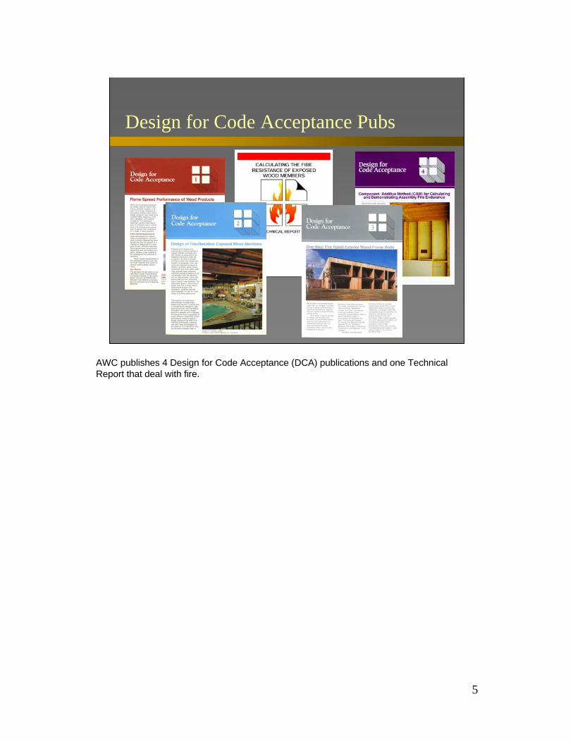
Design for Code Acceptance Pubs
AWC publishes 4 Design for Code Acceptance (DCA) publications and one Technical Report that deal with fire.
6
Outline
• DCA1: Fire Spread Performance of Wood Products• DCA3: Fire Rated Wood Wall Assemblies• DCA4: Component Additive Method (CAM) for
Calculating and Demonstrating AssemblyFire Endurance
• DCA2: Design of Fire-Resistive Exposed Wood Members
• TR10: Calculating the Fire Resistance of ExposedWood Members
• Detailing for Fire Control
This presentation will highlight all 5 documents and show by example how to use the information contained in them. Also, information on detailing for the prevention of fire spread will be covered.
7
Design for Code Acceptance 1
DCA 1Fire Spread Performance of Wood Products
Design for Code Acceptance 1 (DCA 1): Flame Spread Performance of Wood Products.
8
Design for Code Acceptance 1
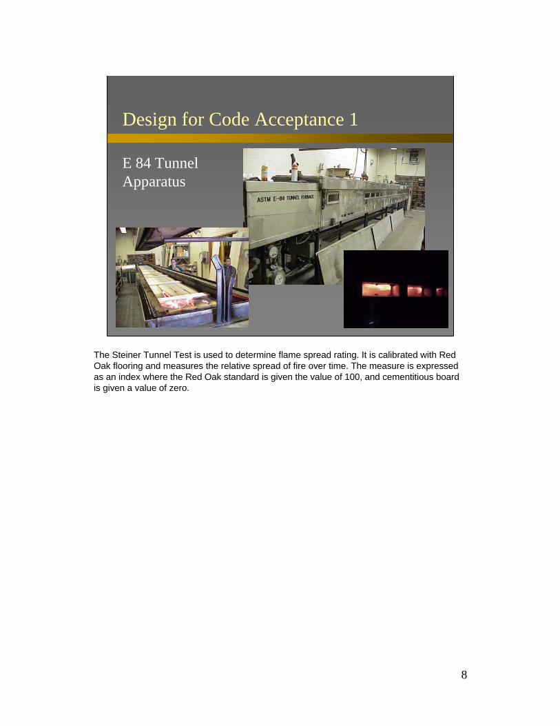
E 84 Tunnel Apparatus
The Steiner Tunnel Test is used to determine flame spread rating. It is calibrated with Red Oak flooring and measures the relative spread of fire over time. The measure is expressed as an index where the Red Oak standard is given the value of 100, and cementitious board is given a value of zero.

9
DCA 1: Flame Spread Ratings for Various Wood Products
Class I or A 0 - 25fire retardant treated wood
Class II or B 26 - 75redwoodcedar
Class III or C 76 - 200most other wood speciessoftwood plywoodhardwood plywoodparticleboard
based on Red Oak = 100
Typical flame spread ratings for various woods are grouped for acceptance in the building code provisions. The lower the rating number, the lower the ability of flame to spread. Some examples of flame spread rating numbers are: •FRTW: 0-25•Redwood & Cedar: 26-75•Other woods: 76-200
DCA 1 now lists flame spread ratings for a variety of domestic wood species and materials and is updated frequently on the web as new material ratings become available.
10
Design for Code Acceptance 3
DCA 3Fire Rated Wood Wall Assemblies
revised with new title and contents 2001
DCA 3: One-hour Fire Rated Exterior Walls.

11
DCA 3: Designing for Fire Endurance
Tools for designing wood frame construction to provide fire endurance:
• traditional ASTM E-119 Assemblies• Component Additive Method (DCA 4)• Beam/Column Calculation Method (TR10)
There are several code accepted methods for designing to provide fire endurance. ASTM E119 assemblies; component additive method (CAM); beam/column calculation method. The latter two methods will be discussed later in order of complexity.
DCA 3 lists and describes complete assemblies that have been approved to meet a specific time rating for fire endurance. This is the simplest approach to designing to meet a given fire endurance requirement in the building code - simply pick an approved assembly that meets the time required, i.e. a one-hour fire assembly. Each assembly has been furnace-tested to the standard ASTM E119.

12
ASTM E-119 Joist Assembly
Typical 1 hour rated assembly:19/32" plywood
15/32" plywood
2" x 10" joists @ 16" o/c
1/2" type X gypsum wallboard
The figure above shows a 1-hr E119 joist assembly (UL512). It uses ½" type X gypsum board on 2x10 floor joists with 2 layers of plywood: 19/32" flooring over 15/32" subfloor.
13
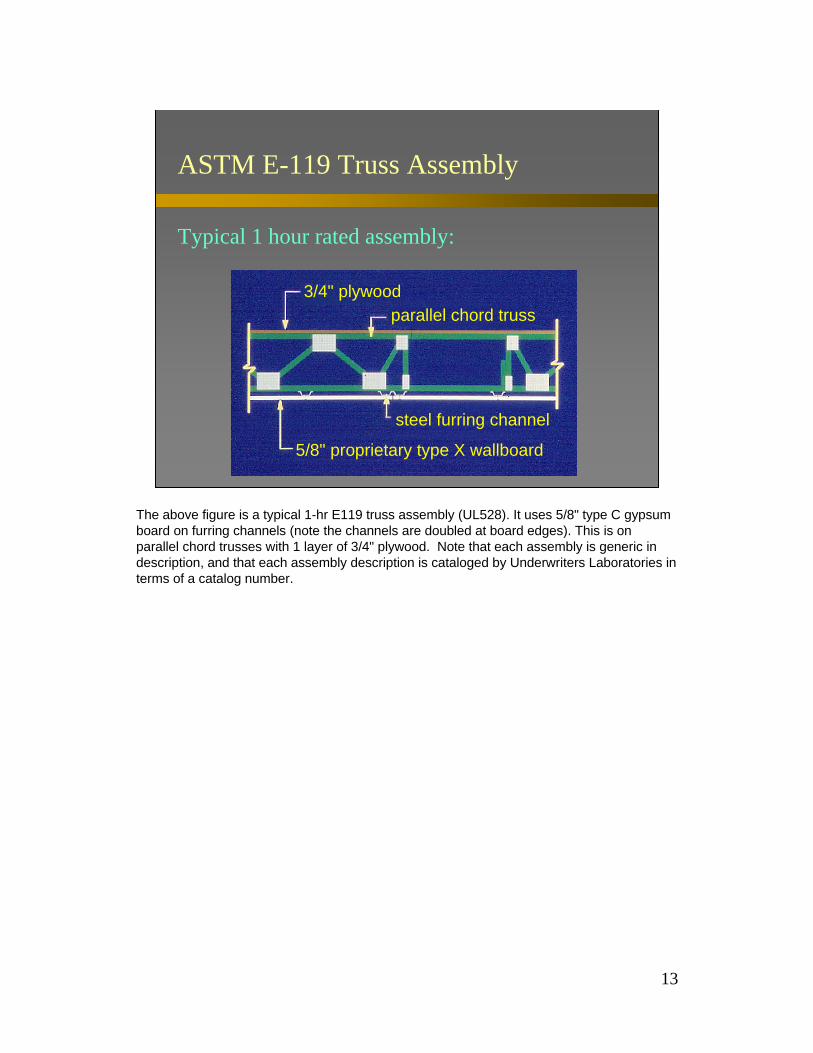
ASTM E-119 Truss Assembly
Typical 1 hour rated assembly:
3/4" plywoodparallel chord truss
steel furring channel
5/8" proprietary type X wallboard
The above figure is a typical 1-hr E119 truss assembly (UL528). It uses 5/8" type C gypsum board on furring channels (note the channels are doubled at board edges). This is on parallel chord trusses with 1 layer of 3/4" plywood. Note that each assembly is generic in description, and that each assembly description is cataloged by Underwriters Laboratories in terms of a catalog number.

14
ASTM E-119 Truss Assembly
As constructed:
The figure above shows what that assembly looks like as constructed prior to testing in an E-119 furnace.
15
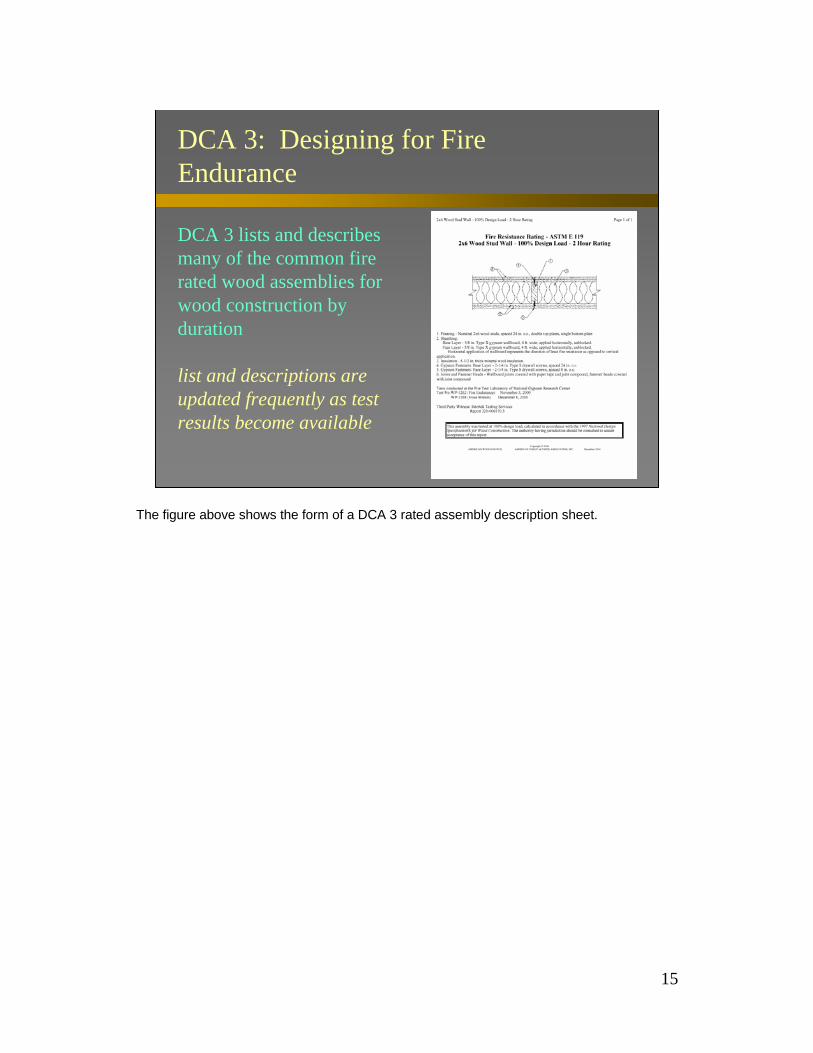
DCA 3: Designing for Fire Endurance
DCA 3 lists and describes many of the common fire rated wood assemblies for wood construction by duration
list and descriptions are updated frequently as test results become available
The figure above shows the form of a DCA 3 rated assembly description sheet.

16
Design for Code Acceptance 4
DCA 4 Component Additive Method (CAM) for Calculating and Demonstrating Assembly Fire Endurance
DCA 4: Component Additive Method (CAM) for Calculating and Demonstrating Assembly Fire Endurance. Should a tested assembly, not be available, or applicable, one can “create” a conforming assembly using the Component Additive Method. This is most frequently utilitarian when designing in existing structures where the existing assemblies may not be easily altered.

17
DCA 4: CAM Background
Component Additive Method (CAM)• developed by NRC using NBS tests• recognized by SBCCI and ICBO• published by BOCA• for new and existing assemblies
CAM was developed by the National Research Center of Canada using National Building Science data, based upon Harmathy's 10 rules of fire endurance. Recognized by ICBO and SBCCI and published by BOCA, the CAM applies to both new and existing assemblies. The complete background to CAM is described in DCA 4, along with the required tables and examples for design. CAM is implemented by adding time contributions from each materials layer through the thickness of the entire assembly.

18
DCA 4: CAM Membrane Table
Time Assigned to Protective Membranes
3/8" Douglas-fir plywood, phenolic bonded 51/2" Douglas-fir plywood, phenolic bonded 105/8" Douglas-fir plywood, phenolic bonded 153/8" gypsum board 101/2" gypsum board 155/8" gypsum board 201/2" Type X gypsum board 255/8" Type X gypsum board 40Double 3/8" gypsum board 251/2" + 3/8" gypsum board 35Double 1/2" gypsum board 40
Description of Finish Time (minutes)
Here is an example of the table from DCA 4 of times assigned to protective membrane materials, i.e. ½" gypsum board: 15 minutes; 5/8" doug-fir plywood: 15 min.

19
DCA 4: Wall Membranes
Membranes on Exterior Face of Walls
5/8" T&G lumber5/16" exterior grade plywood1/2" gypsum board
Sheathingpaper
Lumber siding: orWood shakes & shingles1/4" external grade plywood1/4" hardboardMetal sidingStucco on metal lathMasonry veneer
None None 3/8" external grade plywood
Sheathing Paper Exterior Finish
The table lists the minimum membrane protection required when the assembly is asymmetrical. Membrane protection on each side is required if exposure to fire may occur from either side.

20
DCA 4: CAM Wood Component Table
Assigned Times for Wood Components
Wood studs, 16 inches on center 20
Wood joists, 16 inches on center 10
Wood roof and floor truss assemblies 24 inches on center 5
Description of Frames Time (minutes)
Here is another table from DCA 4 listing assigned times for various wood components, for example:studs 16” o.c. - 20 min.joists 16” o.c. - 10 min.trusses 24” o.c. - 5 min.
21
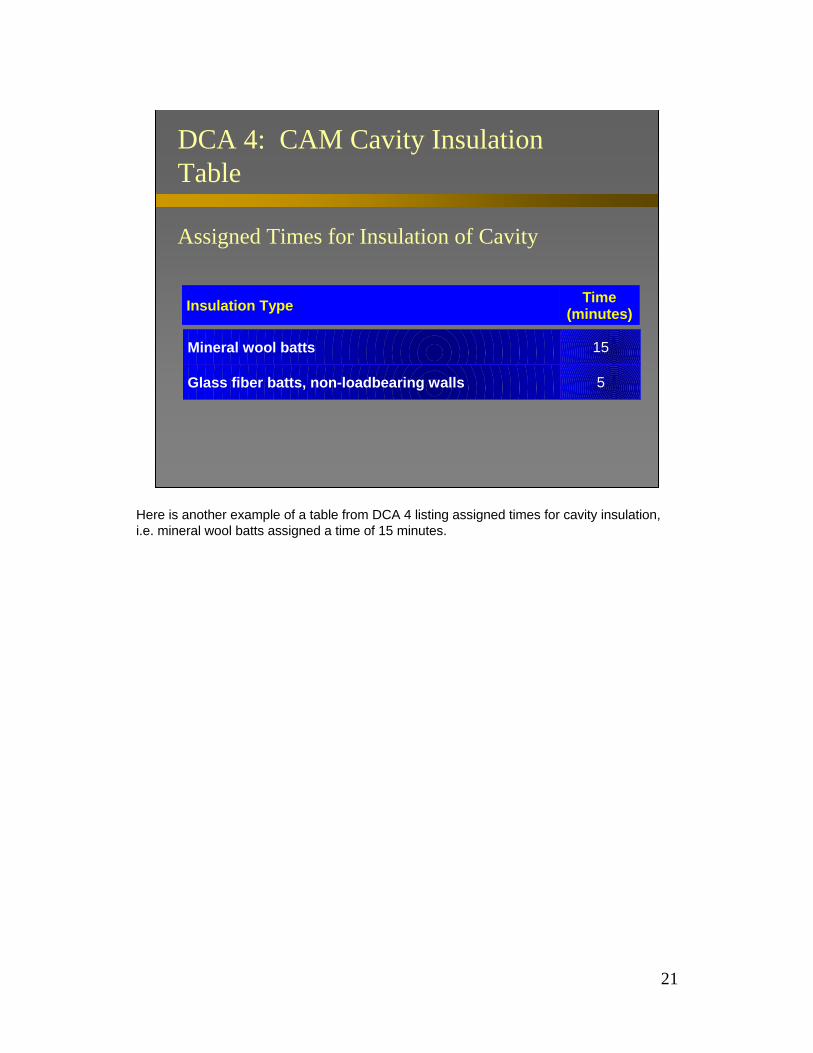
DCA 4: CAM Cavity Insulation Table
Assigned Times for Insulation of Cavity
Mineral wool batts 15
Glass fiber batts, non-loadbearing walls 5
Insulation Type Time (minutes)
Here is another example of a table from DCA 4 listing assigned times for cavity insulation, i.e. mineral wool batts assigned a time of 15 minutes.

22
DCA 4: CAM Example 1
Component Additive Method (CAM) - Interior Wall2" X 4" Wood Stud
5/8" Type X Gypsum Board
2" X 4" Wood Stud 20 minutes 5/8 " Type X Gypsum Board 40 minutesTotal 60 minutes
To apply Component Additive Method, take each material layer in the assembly, find its respective assigned time from the DCA table, and sum the materials times together. The summed time yields the time rating for the assembly.
Example: 2x4 studs@16"o.c. = 20 min.; 2 layers 5/8" type X gypsum board = 40 min.; total = 60 min.
This interior wall assembly would satisfy a 1 hour requirement.
23
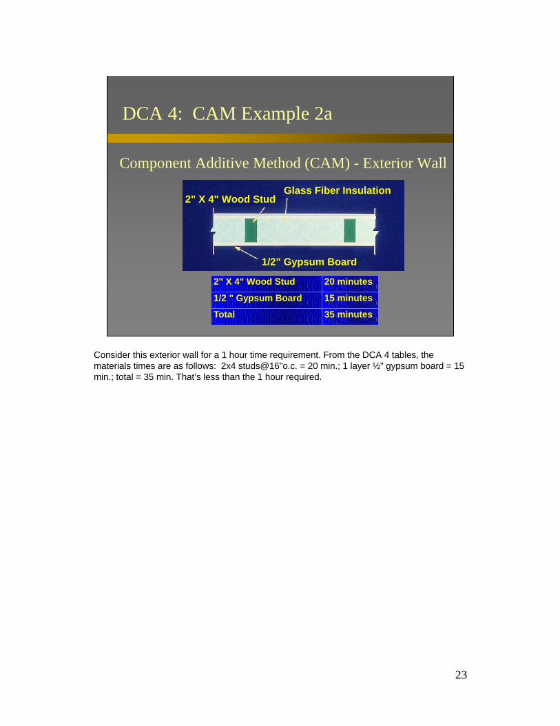
DCA 4: CAM Example 2a
Component Additive Method (CAM) - Exterior Wall
2" X 4" Wood StudGlass Fiber Insulation
1/2" Gypsum Board
2" X 4" Wood Stud 20 minutes
1/2 " Gypsum Board 15 minutes
Total 35 minutes
Consider this exterior wall for a 1 hour time requirement. From the DCA 4 tables, the materials times are as follows: 2x4 studs@16"o.c. = 20 min.; 1 layer ½" gypsum board = 15 min.; total = 35 min. That’s less than the 1 hour required.

24
DCA 4: CAM Example 2b
Component Additive Method (CAM) - Exterior Wall2" X 4" Wood Stud Glass Fiber Insulation
1/2" Gypsum Board & 1/2" Type X Gypsum Board
2" X 4" Wood Stud 20 minutes 1/2 " Gypsum Board 15 minutesTotal 35 minutes1/2" Type X Gypsum Board 25 minutesTotal 60 minutes
To meet the minimum 1 hour requirement, add an additional layer of ½" type X gypsum = 25 min., for a total of 60 min. Now the assembly is OK.

25
Design for Code Acceptance 2
DCA 2Design of Fire-Resistive Exposed Wood Members
Design for Code Acceptance 2 (DCA 2): Design of Fire Resistive Exposed Wood Members. Should you have exposed structural wood material, you can provide meaningful fire protection by design. DCA 2 provides the necessary guidance and formulae based on extensive fire testing and char rate modeling.
26
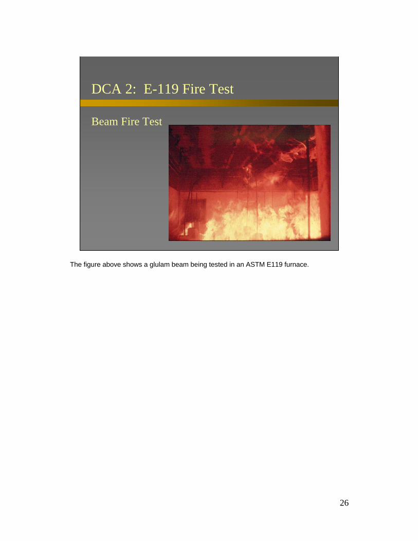
DCA 2: E-119 Fire Test
Beam Fire Test
The figure above shows a glulam beam being tested in an ASTM E119 furnace.

27
DCA 2: Charred Cross-section
Beam Fire Design
Heated zone
Charred wood
W
D
Analysis of wood members subjected to fire yields the following characteristics about their cross section. Wood is a natural insulator that chars from the outside-in at a measurable, predictable rate when exposed to fire. The outer layer is a char layer (sacrificial wood). The heated zone is where some strength reduction in the wood occurs due to elevated temperature. The inner zone is unaffected during the fire. This affords good residual load-carrying ability for the wood member based on the size or cross section of the inner zone.

28
DCA 2: Section Terminology
Design Methodology for Beams and Columns
b is the width (inches) of beam or larger column faced is the depth (inches) of beam or narrower column facez is the load factorr is the load ratiot is the fire endurance time (minutes)
The following terminology is used in this calculation method (see slide).
29
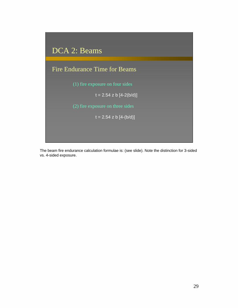
DCA 2: Beams
Fire Endurance Time for Beams
(1) fire exposure on four sides
t = 2.54 z b [4-2(b/d)]
(2) fire exposure on three sides
t = 2.54 z b [4-(b/d)]
The beam fire endurance calculation formulae is: (see slide). Note the distinction for 3-sided vs. 4-sided exposure.
30
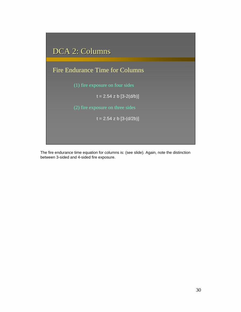
DCA 2: ColumnsDCA 2: Columns
Fire Endurance Time for Columns
(1) fire exposure on four sides
t = 2.54 z b [3-2(d/b)]
(2) fire exposure on three sides
t = 2.54 z b [3-(d/2b)]
The fire endurance time equation for columns is: (see slide). Again, note the distinction between 3-sided and 4-sided fire exposure.
31
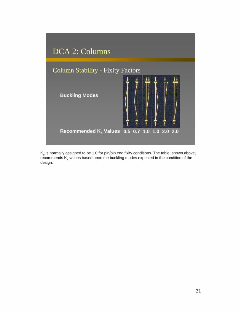
DCA 2: Columns
Column Stability - Fixity Factors
Buckling Modes
Recommended Ke Values 0.5 0.7 1.0 1.0 2.0 2.0
Ke is normally assigned to be 1.0 for pin/pin end fixity conditions. The table, shown above, recommends Ke values based upon the buckling modes expected in the condition of the design.

32
DCA 2: Load Factor
Load Factor zFor columns with Ke /d <11:
z = 1.5 for r ≤ 50
z = 0.9 + 30/r for r > 50
Load factors are shown graphically in DCA 2. Load factor, z, for columns with slenderness ratio Kel/d < 11 (see slide).

33
DCA 2: Load Factor
Load Factor z
For columns with Ke /d >11, and all beams:
z = 1.3 for r ≤ 50
z = 0.7 + 30/r for r > 50
Again note, load factors are shown graphically in DCA 2. Note the distinction for slender columns with Ke l/d > 11 and for all beams (see slide).

34
DCA 2: Load Ratio
Load Ratio r
r =
can be expressed as geometry or other ratio forms since load is a linear variable
Loadmax allowable
loadactual
“r” is the Load Ratio and can be expressed in geometry or in other ratio forms since load is a linear variable (see slide).

35
DCA 2: Exposed Beam Example
Given: 8.75”x24” Glulam beam exposed to fireon 3 sides; Sreq’d = 753 in3
Need: 1 hour rating
Consider this example: Design an 8.75” x 24” glulam beam for 1-hr fire endurance rating assuming 3 sides exposed to fire. Assume a required section modulus (Sreq'd) of 753 in3
based on actual loads.
36
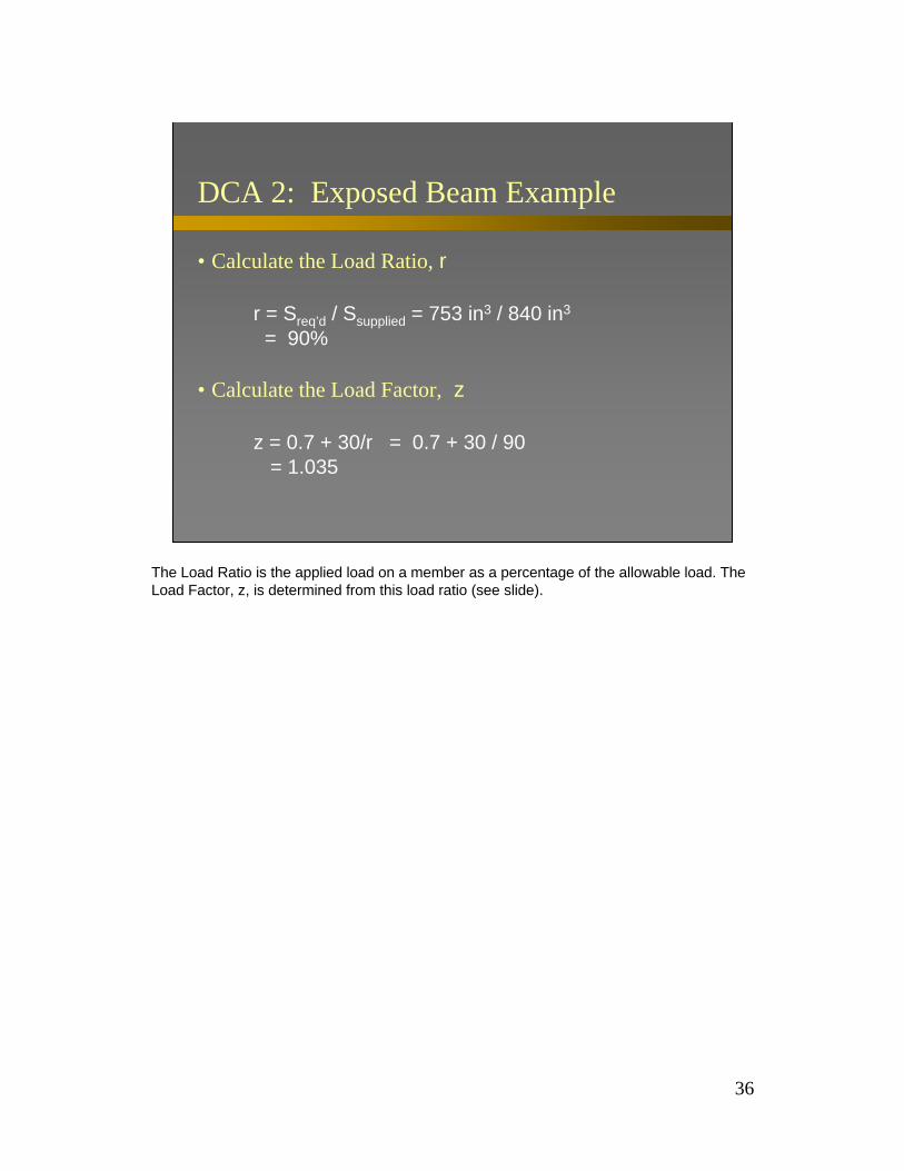
DCA 2: Exposed Beam Example
• Calculate the Load Ratio, r
r = Sreq’d / Ssupplied = 753 in3 / 840 in3
= 90%
• Calculate the Load Factor, z
z = 0.7 + 30/r = 0.7 + 30 / 90 = 1.035
The Load Ratio is the applied load on a member as a percentage of the allowable load. The Load Factor, z, is determined from this load ratio (see slide).

37
DCA 2: Exposed Beam Example
• Calculate the Fire Endurance Time, t
t = 2.54 z b [4-b/d]= 2.54 (1.035)(8.75) [4-(8.75/24)]= 83 minutes
Calculate the fire endurance time in minutes using the time formula for a 3-sided exposed beam (see slide). This is equal to 83 minutes. This beam exceeds the one-hour (60 minutes) requirement in this design. If the time, t, calculated is less than 60 minutes, then to get the one-hour requirement for this exposed beam, the section size would need to be increased slightly.
38
Technical Report 10
TR10Calculating the Fire Resistance of Exposed Wood Members
Technical Report 10 (TR 10): Design of Fire Resistive Exposed Wood Members, forms the technical basis for DCA 2. It is also complete with detailed explanation, test results, and comprehensive calculation examples.
39
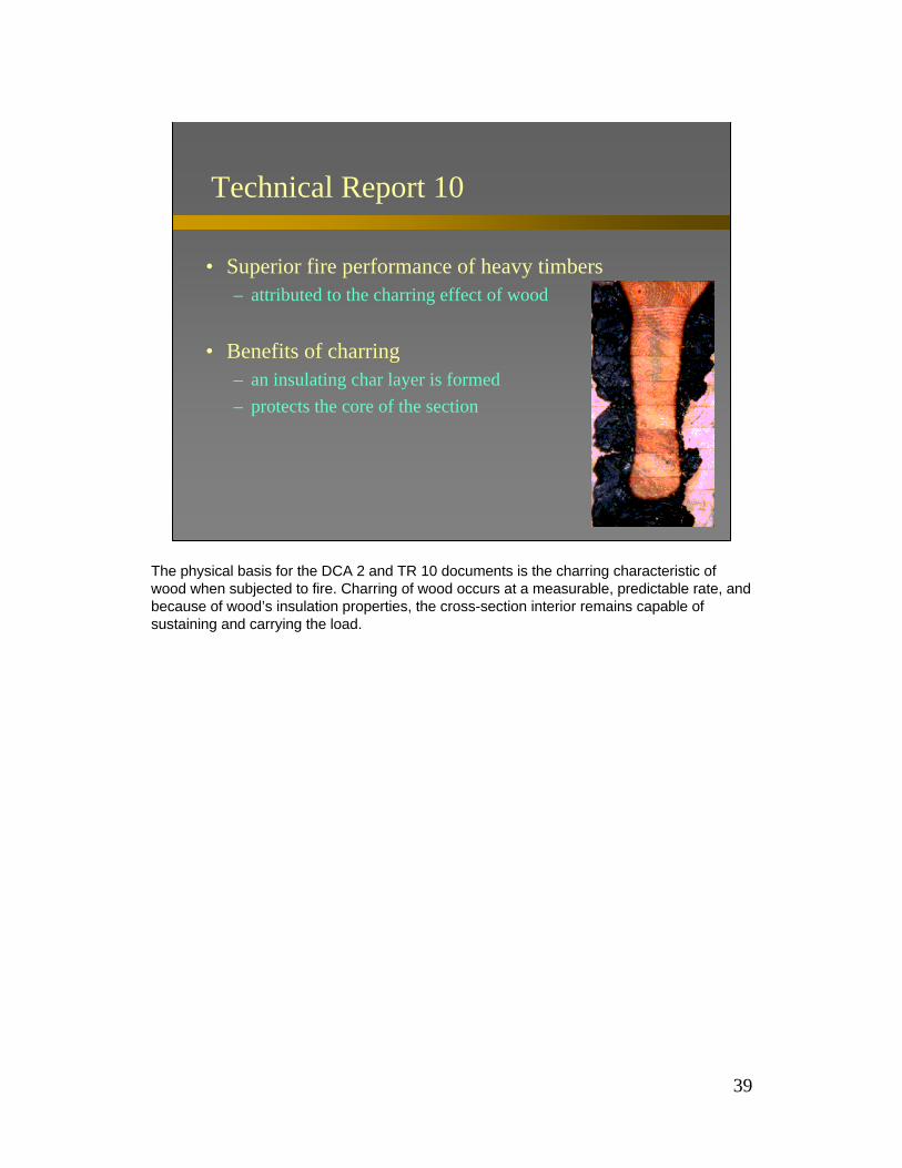
• Superior fire performance of heavy timbers– attributed to the charring effect of wood
• Benefits of charring– an insulating char layer is formed – protects the core of the section
Technical Report 10
The physical basis for the DCA 2 and TR 10 documents is the charring characteristic of wood when subjected to fire. Charring of wood occurs at a measurable, predictable rate, and because of wood’s insulation properties, the cross-section interior remains capable of sustaining and carrying the load.
40
• Experimental charring rates measured in various parts of the world appear to be consistent– North America - Standard fire endurance test ASTM E-119 – many other countries - comparable fire exposure in ISO 834
• Effects of fire on adhesives– synthetic glues used in the manufacture of glulam do not
adversely affect performance
Technical Report 10
Charring rates of wood under standard fire exposure conditions were measured in studies world-wide. Glued products did not perform any differently than their solid counterparts.

41
Analog for Cross-Sectional Dimensions
A standard terminology was established for describing the charred and uncharred section dimensions for two common fire exposures.

42
Estimating Cross-sectional Dimensions due to Charring
• 4-Sided Exposure (i.e. columns) b = B - 2βt d = D - 2βt
• 3-Sided Exposure (i.e. beams) b = B - 2βt d = D - βt
• 2-Sided Exposure (i.e. decking) b = B - βt d = D - βt
where:β is the char rate of the materialt is the fire exposure time
…which resulted in these relations for charred width and depth as shown in the table above.

43
ASCE 29 Method for Beams(Lie Empirical Method)
tf = 2.54 Z B (4 - 2B/D) 4-sided exposure
2.54 Z B (4 - B/D) 3-sided exposure
where:
Z = 1.3 R < 0.50.7 + 0.3 / R R > 0.5
and, where:R is the ratio of applied to allowable load (load ratio)tf is the fire endurance time (minutes)
Here is the ASCE 29 Method for beams of 3- and 4-sided exposure. Note that the the failure time is expressed in minutes (see slide).
44
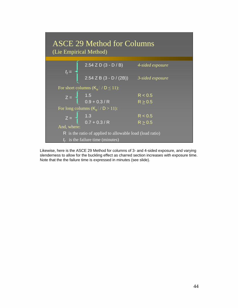
ASCE 29 Method for Columns(Lie Empirical Method)
tf =2.54 Z D (3 - D / B) 4-sided exposure
2.54 Z B (3 - D / (2B)) 3-sided exposure
For short columns (Ke / D < 11):
Z = 1.5 R < 0.50.9 + 0.3 / R R > 0.5
And, where:R is the ratio of applied to allowable load (load ratio)tf is the failure time (minutes)
Z = 1.3 R < 0.50.7 + 0.3 / R R > 0.5
For long columns (Ke / D > 11):
Likewise, here is the ASCE 29 Method for columns of 3- and 4-sided exposure, and varying slenderness to allow for the buckling effect as charred section increases with exposure time. Note that the the failure time is expressed in minutes (see slide).

45
New Mechanics-Based Design Method
• expands the use of large exposed wood members:– loading conditions
– fire exposures
– mechanical properties
– stress interactions
– expanded range of wood products
This design method is a rational approach that allows for exposed structural wood members to be used in structures that could be exposed to fire.

46
Design Considerations
• predicts reduced cross-sectional dimensions
• adjusts for charring at the corners
• accounts for the loss of strength and stiffness in the heated zone
The equations used in this method account for all the charring characteristics of a wood cross-section exposed to fire.
47
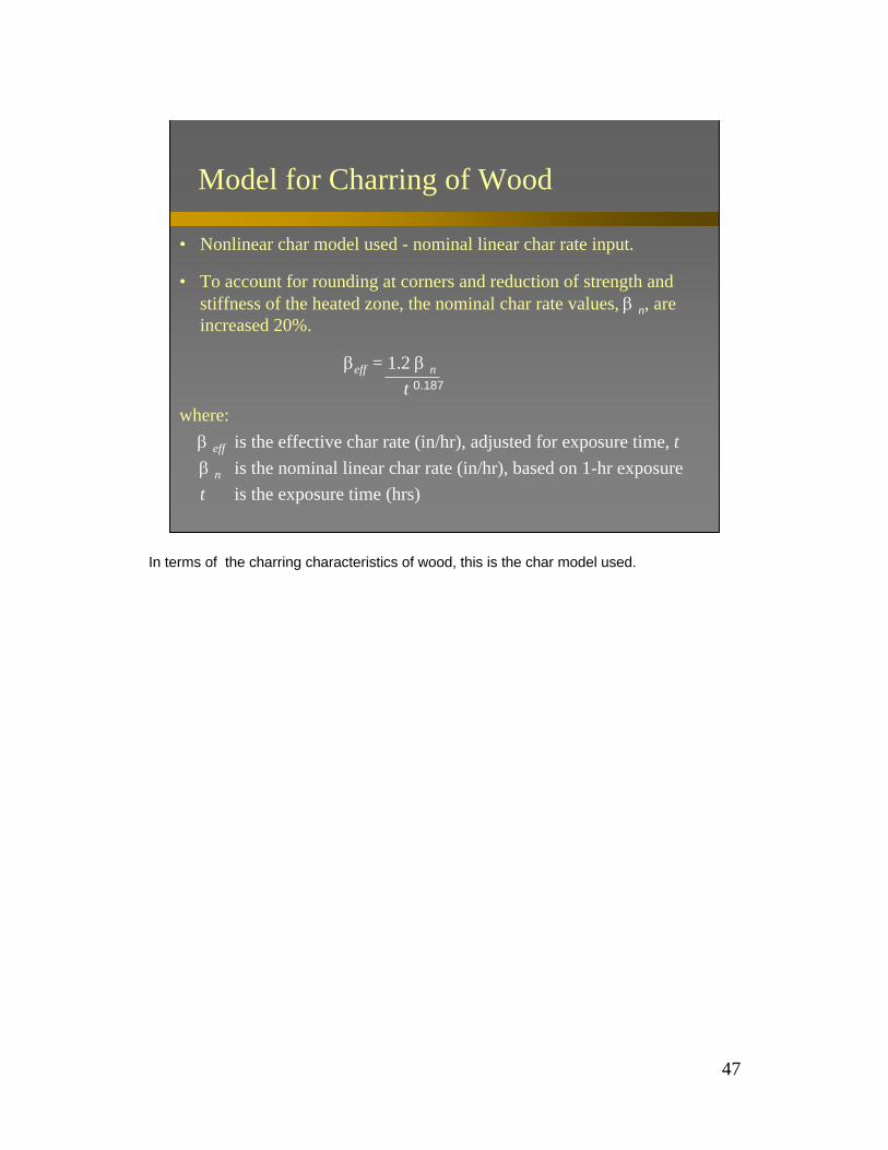
Model for Charring of Wood
• Nonlinear char model used - nominal linear char rate input.
• To account for rounding at corners and reduction of strength andstiffness of the heated zone, the nominal char rate values, β n, are increased 20%.
βeff = 1.2 β n
t 0.187
where:β eff is the effective char rate (in/hr), adjusted for exposure time, tβ n is the nominal linear char rate (in/hr), based on 1-hr exposuret is the exposure time (hrs)
In terms of the charring characteristics of wood, this is the char model used.

48
Effective Char Rates and Char Layer Thickness(for βn = 1.5 inches/hour)
Required Fire Effective Char Effective Char LayerEndurance Rate, βeff Thickness, αchar
(hr) (in/hr) (in)1-Hour 1.80 1.81½-Hour 1.67 2.52-Hour 1.58 3.2
…and these are the charring results based on a typical char rate of 1.5 inches per hour.

49
Design for Member Capacity
Dead Load + Live Load ≤ K * Allowable Design Capacity
Where:K is a factor to adjust from allowable design capacity to
average ultimate capacity
The factor, K, adjusts from allowable design capacity of the member to average ultimate capacity - the maximum capacity the member can physically sustain (no safety factors).

50
Allowable Design Stress to Average Ultimate Strength Adjustment Factor
Member Capacity KBending Moment Capacity, in-lb. 2.85Tensile Capacity, lb. 2.85Compression Capacity, lb. 2.58Beam Buckling Capacity, lb. 2.03Column Buckling Capacity, lb. 2.03
This table lists the values of K for various mode capacities to adjust to an ultimate strength basis.
51
General Comparison
• Given the theoretical derivation of the new mechanics-based design method, existing test results from fire tests of exposed, large wood members were compared against the model predictions.
• International and North American test data were reviewed.
The theoretical model was checked against full scale tests from all over the world.

52
Predicted Time vs. Fire Test Observed Time(Wood Beams Exposed on 3-Sides)
0
20
40
60
80
100
120
140
160Pr
edic
ted
Tim
e to
Fai
lure
(min
utes
)
0 20 40 60 80 100 120 140 160
Observed Time to Failure (minutes)
Mechanics-Based Model Prediction
Model and test agreement were good for wood beams exposed on 3 sides.

53
Predicted Time vs. Fire Test Observed Time(Wood Columns Exposed on 4-Sides)
0
20
40
60
80
100
120
140P
redi
cted
Tim
e to
Fai
lure
(min
utes
)
0 20 40 60 80 100 120 140
Observed Time to Failure (minutes)
Mechanics-Based Model Prediction
….also for wood columns exposed on 4 sides.
54
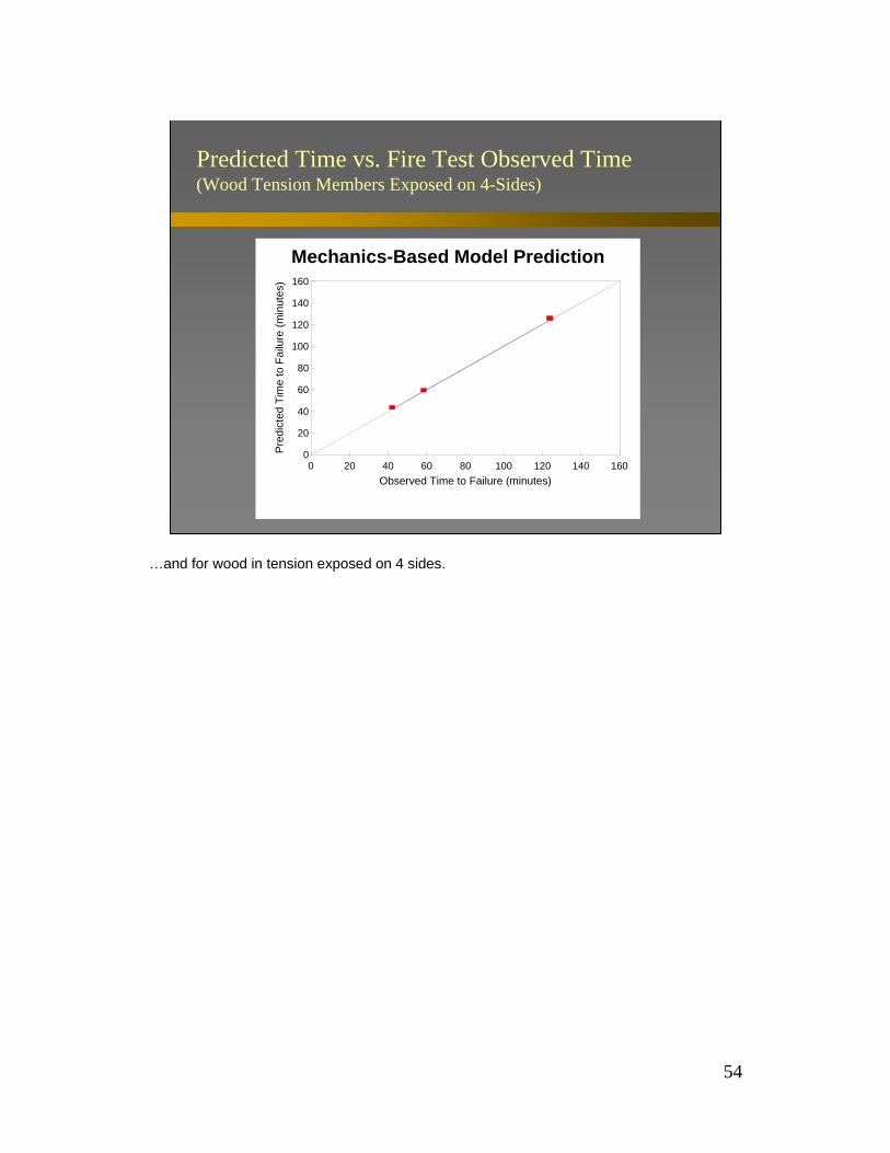
Predicted Time vs. Fire Test Observed Time(Wood Tension Members Exposed on 4-Sides)
0
20
40
60
80
100
120
140
160P
redi
cted
Tim
e to
Fai
lure
(min
utes
)
0 20 40 60 80 100 120 140 160Observed Time to Failure (minutes)
Mechanics-Based Model Prediction
…and for wood in tension exposed on 4 sides.

55
Predicted Time vs. Fire Test Observed Time(Decking Exposed on Bottom Side)
0
20
40
60
80
100P
redi
cted
Tim
e to
Fai
lure
(min
utes
)
0 20 40 60 80 100
Observed Time to Failure (minutes)
Mechanics-Based Model Prediction
…as well as for decking exposed on the bottom side.
56
Technical Report 10
– Expands the uses for large, exposed wood members (tension, bending/compression, bending/tension members, decking)
– Expands applicability of current methods to other EWP’s (SCL)
– Expands use of large, exposed wood members to 2 hour fire endurance applications.
The model and methodology described in TR 10 holds several advantages for structural wood applications.

57
• Douglas fir glulam beams– Span L = 18 feet– Spaced at s = 6 feet
• Design Load– qlive = 100 psf– qdead = 15 psf
• Timber decking nailed to the compression edge of beams provides lateral bracing
Size the beam for required bending strength for 1 hour fire duration
TR 10: Design Example
Here is a detailed example, worked from start to finish - with more depth than that presented previously in DCA 2.
Consider Douglas fir beams spanning 18 feet and spaced 6 feet apart. The beams support 100 psf live load and 15 psf dead load. Timber decking laterally braces the compression flange of the beams.
Size the beam for a 1 hour rating.
58
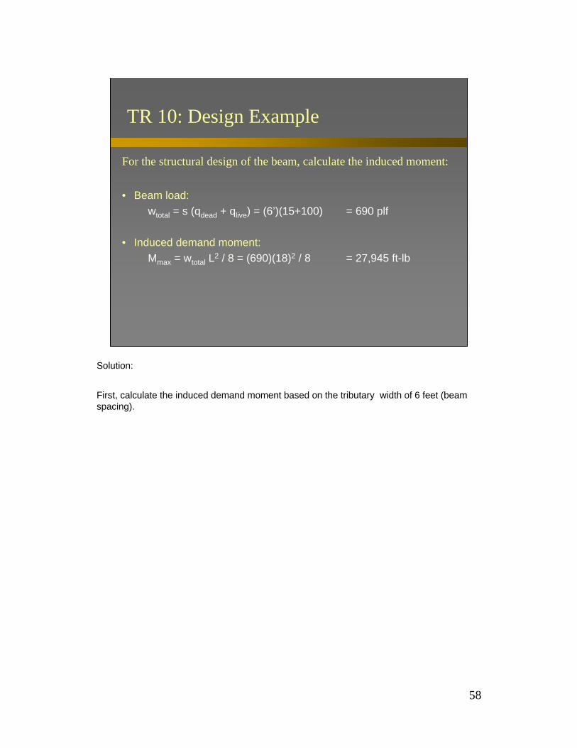
For the structural design of the beam, calculate the induced moment:
• Beam load:wtotal = s (qdead + qlive) = (6’)(15+100) = 690 plf
• Induced demand moment:Mmax = wtotal L2 / 8 = (690)(18)2 / 8 = 27,945 ft-lb
TR 10: Design Example
Solution:
First, calculate the induced demand moment based on the tributary width of 6 feet (beam spacing).
59
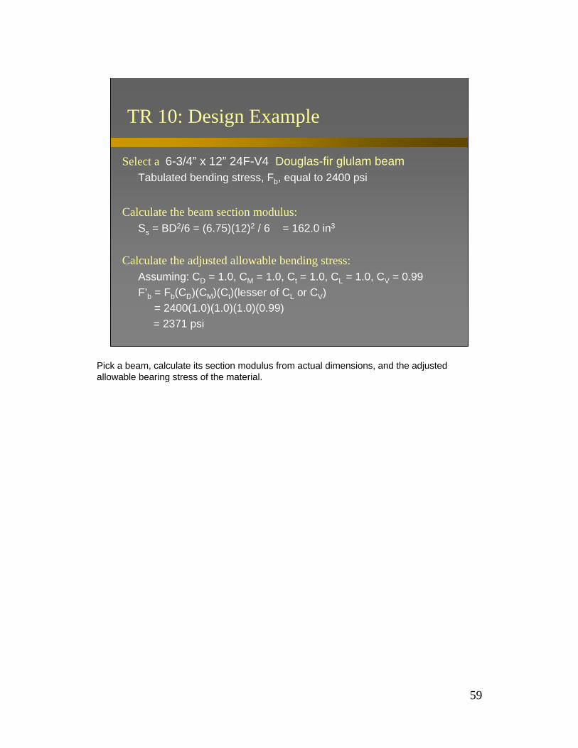
Select a 6-3/4” x 12” 24F-V4 Douglas-fir glulam beamTabulated bending stress, Fb, equal to 2400 psi
Calculate the beam section modulus:Ss = BD2/6 = (6.75)(12)2 / 6 = 162.0 in3
Calculate the adjusted allowable bending stress:Assuming: CD = 1.0, CM = 1.0, Ct = 1.0, CL = 1.0, CV = 0.99F’b = Fb(CD)(CM)(Ct)(lesser of CL or CV)
= 2400(1.0)(1.0)(1.0)(0.99) = 2371 psi
TR 10: Design Example
Pick a beam, calculate its section modulus from actual dimensions, and the adjusted allowable bearing stress of the material.

60
Calculate the design resisting moment:M’ = F’b Ss = (2371)(162) / 12 = 32,009 ft-lb
Structural Capacity Check: M’ > Mmax
32,009 ft-lb > 27,945 ft-lb
TR 10: Design Example
Multiply the adjusted allowable bending stress by the section modulus to get the maximum resisting moment offered by your chosen beam. Check for adequacy, and in this case, OK.
61
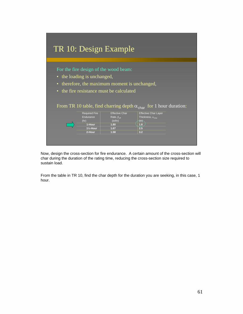
For the fire design of the wood beam:• the loading is unchanged,• therefore, the maximum moment is unchanged,• the fire resistance must be calculated
From TR 10 table, find charring depth αchar for 1 hour duration:
TR 10: Design Example
Required Fire Effective Char Effective Char LayerEndurance Rate, βeff Thickness, αchar
(hr) (in/hr) (in) 1-Hour 1.80 1.8
1½-Hour 1.67 2.5 2-Hour 1.58 3.2
Now, design the cross-section for fire endurance. A certain amount of the cross-section will char during the duration of the rating time, reducing the cross-section size required to sustain load.
From the table in TR 10, find the char depth for the duration you are seeking, in this case, 1 hour.

62
TR 10: Design Example
Substitute in residual cross-section dimensions for 3-sided beam into the section modulus relation, i.e.:
• 3-Sided Exposure (i.e. beams) b = B - 2βt d = D - βt= B - 2αchar = D - αchar
Calculate charred beam section modulus exposed on 3-sides:Sf = (B-2αchar)(D- αchar)2 / 6 = (6.75 - 2(1.8))(12-1.8)2 / 6
= 54.6 in3
Determine the charred section dimensions and calculate a new charred section modulus for the residual section.

63
TR 10: Design Example
Calculate the adjusted allowable bending stress (some adjustment factors don’t apply and may have been other than 1.0 before):F’b = Fb(lesser of CL or CV) = 2400(0.99) = 2371 psi
Calculate strength resisting moment using charred cross-section:M’ = K F’b Sf = (2.85)(2371)(54.6)/12 = 30,758 ft-lb
Fire Capacity Check: M’ > Mmax
30,758 ft-lb > 27,945 ft-lb
Recalculate the adjusted allowable bending stress, since not all of the adjustment factors apply here and may have been other than 1.0 before.
Determine the strength resisting moment based on the charred cross-section, and in this case is good for a 1 hour fire duration.

64
TR 10 Conclusions
• Full-scale test results indicate that the mechanics-based method will conservatively estimate the fire endurance time of large, exposed wood members.
• Given the theoretical derivation of the new mechanics-based design method, it can be easily incorporated in current wood structural design provisions.
• Incorporation of new mechanics-based method in the NDS will assist in the proper design of large, exposed wood members for standard fire exposures.
TR 10 concludes that the modeled behavior is conservatively accurate, that it can be easily implemented as a design process, and that will permit designers to use exposed large section wood members in structural applications that could be subject to fire exposure.

65
Standardization of New Method
New Design Method has been approved for inclusion in:
2001 National Design Specification® for Wood Construction.
This design approach has been approved for inclusion in the 2001 NDS.

66
Detailing for Fire Control
To reduce the spread of fire, use:• fire blocking
– prevents movement of flame and gases to other areas of the building through small concealed spaces in framing and building components
• draft stopping– prevents movement of air, smoke, flame, and gases to
other areas of the building through large concealed spaces such as attics and floor assemblies with suspended ceilings or open-web trusses
Apart from designing cross-sections to withstand fire endurance, there are other design provisions that can be implemented to reduce the spread of fire in wood frame buildings. Two compartmentalization techniques have been shown to be effective to this end: fire blocking, and draft stopping. The difference between the two is scale - fire blocking for small openings, and draft stopping for separating large assemblies.

67
Detailing for Fire Control
Fire Blocking: WallsBalloon Framing
2x fireblock betweenwalls and floors
2x to fireblockstud space
Continuous studs2 or more stories
2x plates act asfireblock betweenwall and attic
Lack of fire blocking in balloon framing can quickly lead to catastrophic results, since flame can quickly climb through wall and floor cavities through chimney effect. Here are key locations to limit the spread of fire through the cavities of a balloon frame.

68
Detailing for Fire Control
Fire Blocking: WallsPlatform Framing
2x plates act asfireblock betweenwalls and floor
2x plates act asfireblock betweenwall and attic
2x plates act asfireblock betweenwall and floor
Platform framing offers a little more flame spread protection because of the platform nature of the framing. Here, continuity of the fire blocks is important.

69
Detailing for Fire Control
Fire Blocking: Walls at Soffits Subfloor or underlayment
2x fireblock
2x top plates
Soffit
Fire blocks at soffit locations offer protection from flame spread into the soffit cavity.
70
Detailing for Fire Control
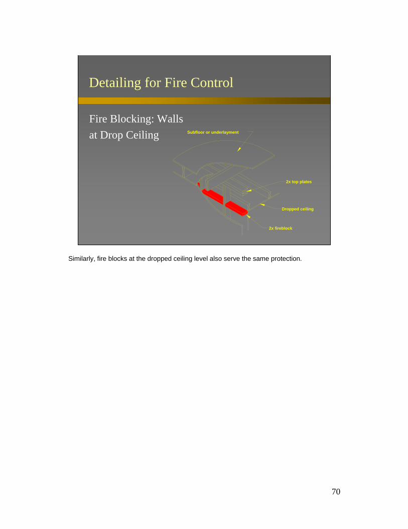
Fire Blocking: Walls at Drop Ceiling Subfloor or underlayment
2x fireblock
Dropped ceiling
2x top plates
Similarly, fire blocks at the dropped ceiling level also serve the same protection.

71
Detailing for Fire Control
Fire Blocking Walls: at Cove Ceiling Subfloor or underlayment
2x fireblock
2x top plates
Cove ceiling
…as well as at ceiling coves.

72
Detailing for Fire Control
Fire Blocking: Stairs
2x Fireblock at topand bottom betweenstringers
To prevent fire from migrating into the joist spaces of floors, fire blocks should be located at the top and bottom of stair runs. Often framing headers serve this function.

73
Detailing for Fire Control
Fire Blocking: Pipes
Approvednoncombustiblefirestop
Plate
2x Scab to reduceopening
Crevices around piping offer a sneaky way for fire to slip into a cavity. A fire block is needed here.

74
Detailing for Fire Control
Fire Blocking: Chimneys
Approvednoncombustiblefireblock
Floor level
A non-combustible fire block is to provided at all chimney openings to limit fire migration upward beside the chimney.

75
Detailing for Fire Control
Draft Stopping: Single Family DwellingsFloor / Ceiling
Drop Ceiling
of draftstop is limitedArea on either side
Draftstop
Floor Joists
To prevent the spread of flame through assemblies, draft stopping is used. One application is compartmentalization of false or dropped ceilings into void volumes that are smaller so that fire is confined.

76
Detailing for Fire Control
Draft Stopping: Single Family DwellingsFloor / Ceiling
Drop Ceiling
Draftstop
Area on either side ofdraftstop is limited
Open-Web trusses
For trussed floors or ceilings, sheathing the truss will compartmentalize the void space into smaller volumes.

77
Detailing for Fire Control
Draft Stopping: Multi-Family (2 or more) DwellingsFloor / Ceiling
Tenant separation wallDraftstop in line with tenantseparation wall
Drop Ceiling
Ceiling joist
Draft stopping between dwelling units in the void space over tenant separation walls will also help to confine fire.
78
Detailing for Fire Control
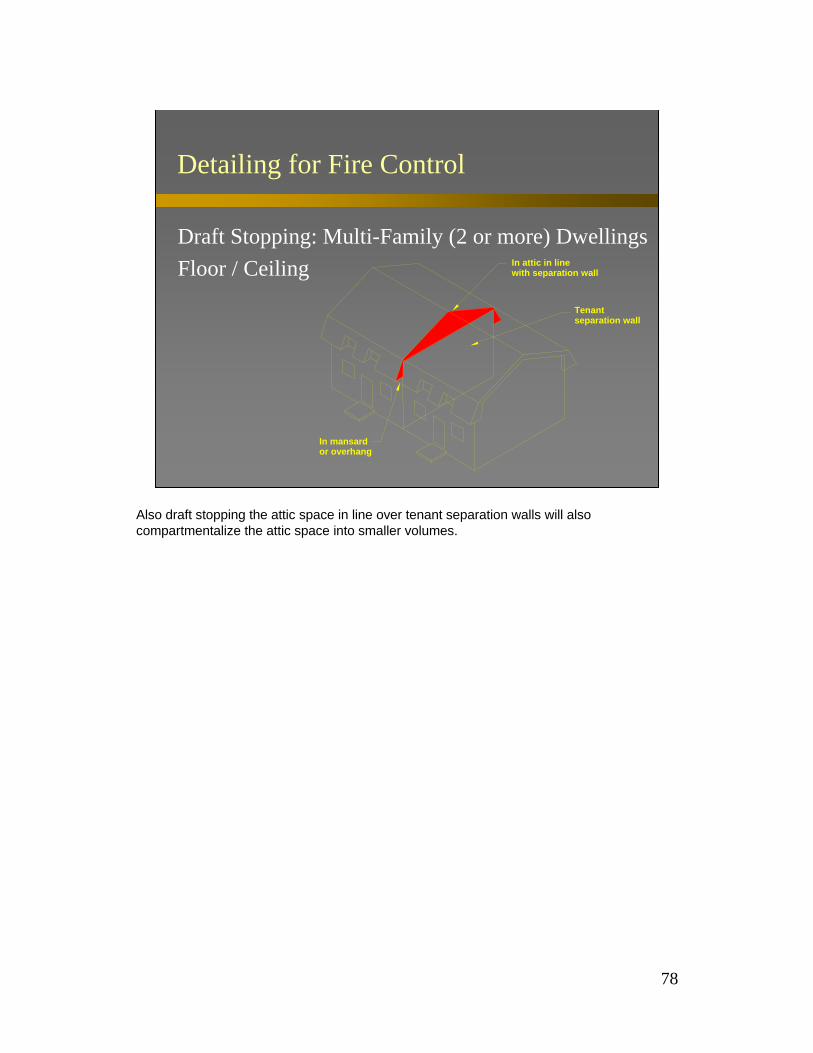
Draft Stopping: Multi-Family (2 or more) DwellingsFloor / Ceiling
In mansardor overhang
Tenant separation wall
In attic in linewith separation wall
Also draft stopping the attic space in line over tenant separation walls will also compartmentalize the attic space into smaller volumes.
79
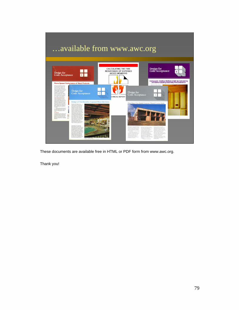
…available from www.awc.org
These documents are available free in HTML or PDF form from www.awc.org.
Thank you!
80
Appendix - Test Data
Appendix - Test Data
81
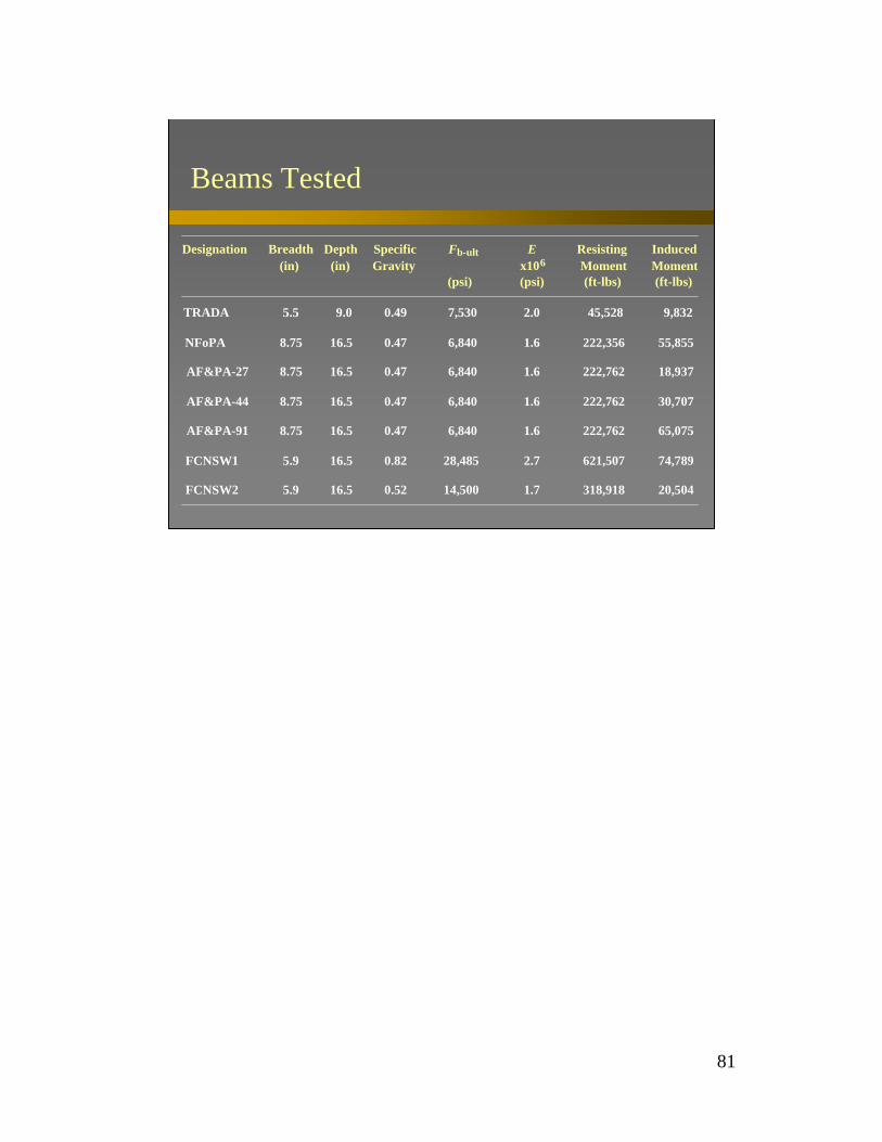
Beams Tested
Designation Breadth(in)
Depth(in)
SpecificGravity
Fb-ult
(psi)
Ex106
(psi)
ResistingMoment(ft-lbs)
InducedMoment(ft-lbs)
TRADA 5.5 9.0 0.49 7,530 2.0 45,528 9,832
NFoPA 8.75 16.5 0.47 6,840 1.6 222,356 55,855
AF&PA-27 8.75 16.5 0.47 6,840 1.6 222,762 18,937
AF&PA-44 8.75 16.5 0.47 6,840 1.6 222,762 30,707
AF&PA-91 8.75 16.5 0.47 6,840 1.6 222,762 65,075
FCNSW1 5.9 16.5 0.82 28,485 2.7 621,507 74,789
FCNSW2 5.9 16.5 0.52 14,500 1.7 318,918 20,504

82
Columns tested in France
Designation Depth(in)
Breadth(in)
SpecificGravity(lb/ft3)
Fc-ult
(psi)
Ex106
(psi)
ResistingCapacity
(lbs)
InducedLoad(lbs)
CSTB44 7 7.875 0.56 2,565 1.6 132,365 39,790
CSTB45 7 7.875 0.56 2,565 1.6 132,365 39,790

83
Columns tested in Germanyby Stanke et al.
Designation Depth(in)
Breadth(in)
SpecificGravity
Fc-ult
(psi)
Ex106(psi)
ResistingCapacity
(lbs)
InducedLoad(lbs)
R14A 5.5 5.5 0.44 7,368 2.5 84,644 19,026
R14B 5.5 5.5 0.45 7,929 2.3 80,310 19,026
R14C 5.5 5.5 0.45 8,131 2.4 82,217 9,524R14D 5.5 5.5 0.43 7,447 2.2 75,740 14,264
H14A 5.5 5.5 0.44 8,050 2.0 70,825 19,026
H14B 5.5 5.5 0.48 7,652 2.4 82,598 19,026
H14C 5.5 5.5 0.45 8,131 2.4 82,217 9,524H14D 5.5 5.5 0.43 7,447 2.2 75,740 14,264
H14/24A 5.5 9.5 0.41 6,243 1.7 99,126 32,628
H14/24B 5.5 9.5 0.41 6,169 1.6 98,033 32,628H14/30A 5.5 11.75 0.45 6,914 1.7 130,414 40,786
H14/30B 5.5 11.75 0.47 8,690 2.7 198,238 20,393
H14/30C 5.5 11.75 0.46 7,165 1.8 134,828 20,393

84
Columns tested in Germanyby Stanke et al.
H14/40 5.5 15.75 0.45 6,675 1.6 158,898 54,234
R15A 5.875 5.875 0.38 5,995 1.8 78,944 24,030
R15B 5.875 5.875 0.38 5,970 1.8 78,629 24,030H15A 5.875 5.875 0.40 6,515 1.9 85,341 24,030
H15B 5.875 5.875 0.37 5,868 1.7 77,371 24,030
R16 5.875 5.875 0.31 4,302 1.3 72,417 29,432
H16A 6.25 6.25 0.37 5,723 1.7 94,688 29,432
H16B 6.25 6.25 0.40 6,595 1.9 108,172 29,432
R16/30 6.25 11.75 0.41 5,944 1.5 163,784 27,558
H16/30A 6.25 11.75 0.42 6,229 1.6 171,131 55,116
H16/30B 6.25 11.75 0.44 6,666 1.7 182,354 55,116
H16/30C 6.25 11.75 0.43 6,470 1.6 177,337 55,116
H16/30D 6.25 11.75 0.40 5,710 1.5 157,743 27,558
Designation Depth(in)
Breadth(in)
SpecificGravity
Fc-ult
(psi)
Ex106(psi)
ResistingCapacity
(lbs)
InducedLoad(lbs)
85
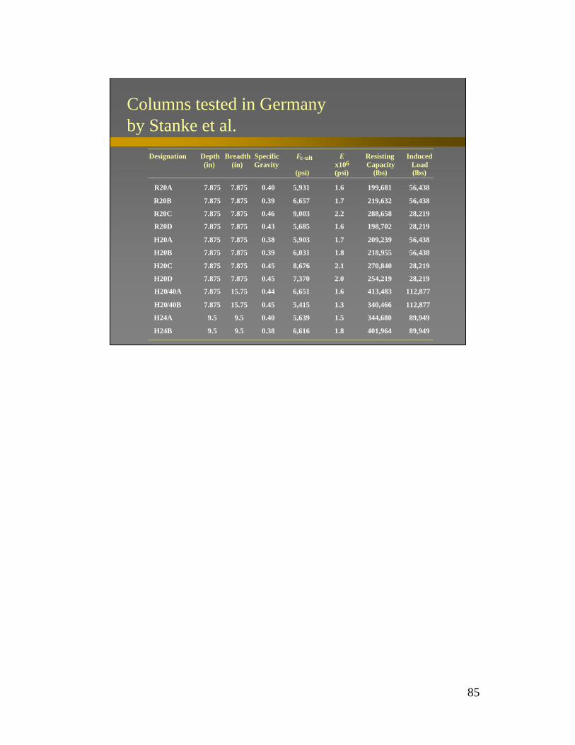
Columns tested in Germanyby Stanke et al.
Designation Depth(in)
Breadth(in)
SpecificGravity
Fc-ult
(psi)
Ex106(psi)
ResistingCapacity
(lbs)
InducedLoad(lbs)
R20A 7.875 7.875 0.40 5,931 1.6 199,681 56,438
R20B 7.875 7.875 0.39 6,657 1.7 219,632 56,438
R20C 7.875 7.875 0.46 9,003 2.2 288,658 28,219
R20D 7.875 7.875 0.43 5,685 1.6 198,702 28,219
H20A 7.875 7.875 0.38 5,903 1.7 209,239 56,438
H20B 7.875 7.875 0.39 6,031 1.8 218,955 56,438
H20C 7.875 7.875 0.45 8,676 2.1 270,840 28,219
H20D 7.875 7.875 0.45 7,370 2.0 254,219 28,219
H20/40A 7.875 15.75 0.44 6,651 1.6 413,483 112,877
H20/40B 7.875 15.75 0.45 5,415 1.3 340,466 112,877
H24A 9.5 9.5 0.40 5,639 1.5 344,680 89,949
H24B 9.5 9.5 0.38 6,616 1.8 401,964 89,949
86
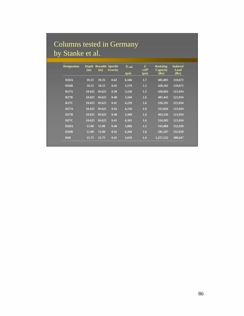
Columns tested in Germanyby Stanke et al.
Designation Depth(in)
Breadth(in)
SpecificGravity
Fc-ult
(psi)
Ex106(psi)
ResistingCapacity
(lbs)
InducedLoad(lbs)
H26A 10.25 10.25 0.42 6,346 1.7 485,005 110,672
H26B 10.25 10.25 0.42 5,579 1.5 428,165 110,672
R27A 10.625 10.625 0.38 5,220 1.3 428,663 121,034
R27B 10.625 10.625 0.40 5,504 1.6 483,442 121,034
R27C 10.625 10.625 0.41 6,229 1.6 528,292 121,034
H27A 10.625 10.625 0.42 6,216 1.9 555,826 121,034
H27B 10.625 10.625 0.40 5,448 1.4 463,536 121,034
H27C 10.625 10.625 0.41 6,181 1.6 524,303 121,034
H28A 11.00 11.00 0.40 5,806 1.5 543,889 132,939
H28B 11.00 11.00 0.42 6,260 1.6 585,187 132,939
H40 15.75 15.75 0.41 5,659 1.4 1,257,232 308,647
87
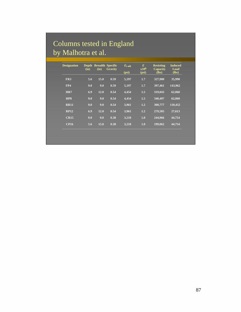
Columns tested in England by Malhotra et al.
Designation Depth(in)
Breadth(in)
SpecificGravity
Fc-ult
(psi)
Ex106(psi)
ResistingCapacity
(lbs)
InducedLoad(lbs)
FR3 5.6 15.0 0.59 5,197 1.7 327,980 35,990
FP4 9.0 9.0 0.59 5,197 1.7 397,461 143,962
HR7 6.9 12.0 0.54 4,454 1.5 319,043 62,060
HP8 9.0 9.0 0.54 4,454 1.5 340,497 62,060
RR11 9.0 9.0 0.54 3,961 1.2 300,777 110,452
RP12 6.9 12.0 0.54 3,961 1.2 279,505 27,613
CR15 9.0 9.0 0.38 3,218 1.0 244,966 44,754
CP16 5.6 15.0 0.38 3,218 1.0 199,062 44,754
88
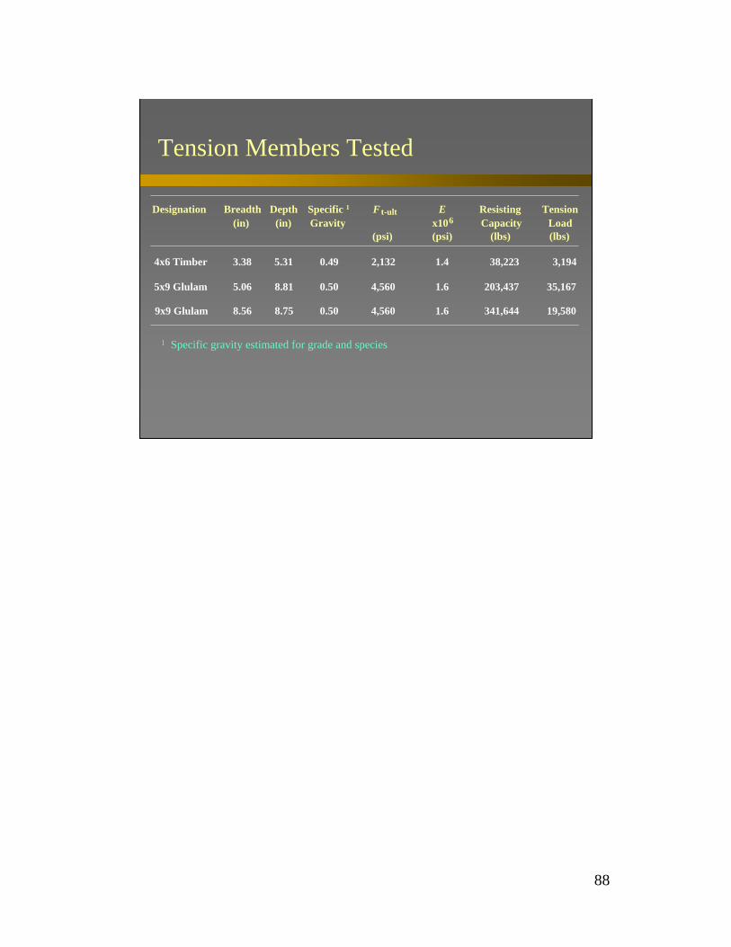
Tension Members Tested
Designation Breadth(in)
Depth(in)
Specific 1Gravity
F t-ult
(psi)
Ex106
(psi)
ResistingCapacity
(lbs)
TensionLoad(lbs)
4x6 Timber 3.38 5.31 0.49 2,132 1.4 38,223 3,194
5x9 Glulam 5.06 8.81 0.50 4,560 1.6 203,437 35,167
9x9 Glulam 8.56 8.75 0.50 4,560 1.6 341,644 19,580
1 Specific gravity estimated for grade and species

89
Designation Species Breadth(in)
Depth(in)
MinducedMult
Measured tf(min)
Calculated tf(min)
Measured and CalculatedDecking Fire Resistance Times
NR = Not Reported
UL #2 Douglas fir 5.5 1.5 0.16 24+ 25
UL #4 Douglas fir 5.5 1.5 0.21 18+ 23
HT1 Subalpine fir 1.625 3.625 0.07 62 58
HT2 Subalpine fir 1.625 3.625 0.07 56 58
HT3 Southern pine 5.625 2.625 0.15 54 53
HT4 Southern pine 5.625 2.625 0.15 NR 53
HT5 Southern pine 5.625 2.625 0.18 NR 49
HT6 Southern pine 5.625 2.625 0.18 45 49

90
Questions?• www.awc.org
– Online eCourses– FAQ’s
• HelpDesk– [email protected]– (202) 463-4713 or (800) 292-2372
• Comments– [email protected]
This concludes this approved continuing education program.