Fire Alarm Plan Submittal Guidelines - · PDF file3rd Party Plan Review Policies Plan Review...
30
Prosper Fire Department 1500 E. First Street Prosper, Texas 75078 972-347-2424 Phone 972-347-3010 Fax www.prospertx.gov Rev. 10-17 Subject to Change Fire Alarm Plan Submittal Guidelines These guidelines are provided as an aid to successful prompt plan review and to insure the minimum information required to inform the extent and intent of the work proposed in the town of Prosper based on the documentation requirements of the adopted national standard NFPA 72. This document includes examples of information presented as figures, tables and best practice recommendations. These examples are not intended to establish the only forms by which this information may be presented. The following are the codes & standards in force in the Town of Prosper Ordinance/Amendments 14-51 effective July 22, 2014 International Fire Code 2012 International Building Code 2012 International Mechanical Code 2012 Most current published edition of NFPA 72 Manufactures Installation Instructions National Electrical Code 2014 Fall 2017 For additional information see our web page at www.prospertx.gov/fire-department/fire-marshal/
-
Upload
truongdien -
Category
Documents
-
view
223 -
download
1
Transcript of Fire Alarm Plan Submittal Guidelines - · PDF file3rd Party Plan Review Policies Plan Review...

Prosper Fire Department 1500 E. First Street Prosper, Texas 75078 972-347-2424 Phone 972-347-3010 Fax www.prospertx.gov
Rev. 10-17 Subject to Change
Fire Alarm Plan Submittal Guidelines These guidelines are provided as an aid to successful prompt plan review and to insure the minimum information required to inform the extent and intent of the work proposed in the town of Prosper based on the documentation requirements of the adopted national standard NFPA 72. This document includes examples of information presented as figures, tables and best practice recommendations. These examples are not intended to establish the only forms by which this information may be presented.
The following are the codes & standards in force in the Town of Prosper Ordinance/Amendments 14-51 effective July 22, 2014
International Fire Code 2012 International Building Code 2012 International Mechanical Code 2012
Most current published edition of NFPA 72 Manufactures Installation Instructions National Electrical Code 2014
Fall 2017
For additional information see our web page at www.prospertx.gov/fire-department/fire-marshal/

P a g e | 2
Table of Contents
3
4
5
3rd Party Plan Review Policies
Plan Review Submittal & Permitting Process – Figure 1
Fire Alarm System Design Submittal Check List –Figure
2 Drawing Submittal Elements – Figure 3 6
7
8
Figure 3a. - Scale Drawing
Figure 3b. - Riser Diagram
Figure 3c. - Circuit Legend 9
10
11
12
13
14
Figure 3d. - Device Legend & Project Materials List
Figure 3e. - Sequence of Operations Matrix
Figure 3f. - Site Map
Figure 3g. - Project Information
Figure 3h. - Design Information
Figure 3i. - Plan Review & Record Drawing Stamp 15
16
17
18
19
20
21 - 22
22 - 25
26 - 28
Fire Alarm Control Unit Battery Calculations Table - Figure 4
Voltage Drop Calculations Table - Figure 5
Other Resources – Figure 6
Fire Alarm System Guidelines Identified in the Prosper Amendments – Figure 7
Elevator Recall & Shunt Trip – Figure 8
Example Device Wiring & Installation Diagrams
Example Installation Diagrams
Supervising Station Communication Methods - Figure 9
Town of Prosper Ordinance/Amendments 14-51 29 - 30

P a g e | 3
3rd Party Plan Review Policies To meet the increasing demands from growth in our community, the following Fire Marshal’s Office interim directive announces effective March 1, 2017.
Bureau Veritas is the exclusive 3rd Party firm for plan review and installation testing & acceptance inspections for all “New Commercial Construction Fire Service” related projects. (All related expenses are the responsibility of the contractor, owner, or designated agent).
Please contact Bureau Veritas at 817-335-8111 for document handling requirements.
System types shall include:
Underground fire service Aboveground sprinkler suppression systems Fire Alarm systems Kitchen hood suppression systems Alternative suppression systems Controlled access systems (building and/or gates)
The processes currently in place for the issuance of permits will remain unchanged through the Fire Marshal’s Office. Please email the stamped approved drawings, data submittal package and the approval review letter to [email protected] in PDF format.
System types shall include:
Underground fire service Aboveground sprinkler suppression systems Fire Alarm systems Alternative suppression systems Kitchen hood suppression systems Controlled egress doors and controlled access gate systems
Contact the Fire Marshal’s Office at 972-346-9469 regarding these requirements.
The Fire Marshal’s Office must receive stamped and approved plans, data submittal package and theapproval review letter in PDF format as three (3) separate attachments before permit issuance.
The policies & procedures established under the Prosper Fire Department Ordinance/Amendments 14-51 for documentation collection shall remain unchanged.
Please consult the Fire Marshal’s web page @ www.prospertx.gov/fire-department/fire-marshal for further information & instructions.
This interim directive shall remain in effect until further notice.
Our goal is to provide a complete and accurate review in the shortest possible time. Our 3rd Party Plan Review Firm(s) will strive to accommodate plan review requests within 10 working days for the first submittals, and 5 working days for interior finishes (less than 5 initiating and less than 10 notification appliances), including re-submittals.
P a g e | 4
Plan Submittal & Permitting Process
Submit drawings, equipment data package, supporting documentation
including narrative To P.F.D.
Approved 3rd Party Plan Review Firm
“Approved” drawings, equipment data package and approval review
letter (as 3 separate attachments) Emailed to
Prosper Fire Marshal’s Office [email protected]
Approval rescinded due to review oversight identified by the Fire Marshal’s office
Prosper Fire Marshal’s office will issue the permit at no
charge via email
Work is allowed to commence Re-submit plans to
Approved 3rd Party Plan Review Firm
Figure 1

P a g e | 5
Submittal Check List Does the submittal contain? Electronic scaled drawings in PDF Format Equipment submittal data package in PDF Format Full company information including, street address, city, state & zip, contact name, office number, cell
number email address, State Registration number (ACR), APS electronic signature in contrasting color
Do the drawings contain? The prescribed Project Information located in the lower left corner with permit number The prescribed Design Information located in the center bottom System Designer stamp with electronic signature in contrasting color located in the lower right corner Site map inset showing adjacent street(s) lower right of the scale drawing North arrow and level/floor identification located under the scale drawing Device legend & project bill of materials located to the lower left of the scale drawing General notes to the far left of the scale drawing Riser diagram located to the upper left of the scale drawing Circuit legend located to the upper far left of the scale drawing All walls and doors All partitions extending to within 15 percent of the ceiling height (where applicable and when known) Room and area descriptions System devices/component locations Locations of fire alarm primary power disconnecting means Locations of monitor/control interfaces to other systems System riser locations Type and number of system components/devices on each circuit, on each floor or level Type and quantity of conductors and conduit (if used) for each circuit Identification of any ceiling over 10 ft. (3.0 m) in height where automatic fire detection is being proposed Details of ceiling geometries, including beams and solid joists, where automatic fire detection is being
proposed Where known, acoustic properties of spaces Device wiring diagrams
Does the Submittal Data Package contain prescribed? Manufacturer’s product information sheets marked with indicating arrows Battery manufacture data sheet/specifications marked with indicating arrows Wire manufacture data sheet/specifications marked with indicating arrows Primary power surge suppressor devices marked with indicating arrows
Do the Drawing Notes contain? Jurisdictional authority Designed-in-accordance-with codes, code dates and local amendments Prescribed initiating circuit wiring description Describe all relevant operation and control functions Describe duct detector operation statement
This check list is provided as a submittal aid only and is not intended to cover every code requirement.
Figure 2

P a g e | 6
Shop Drawing (Installation Documentation) Elements
Scale Drawing
Figure 3a
Floor or Level Identification Graphic Scale
North Arrow
Figure 3a
General Notes Riser Diagram
Figure 3b
Site Map
Figure 3f
Circuit Legend
Figure 3c
Sequence of Operation Matrix
Figure 3e
Device Legend and Project Materials List
Figure 3d
Plan Review & Record Drawing
Stamp
Figure 3i
Project Information
Figure 3g
Figure 3
Design Information
Figure 3h

P a g e | 7
Scale Drawing
Figure 3a

P a g e | 8
Riser Diagram
Figure 3b

P a g e | 9
Circuit Legend
Figure 3c

P a g e | 10
Device Legend & Project Bill of Materials
Figure 3d

P a g e | 11
Sequence of Operation Matrix
Figure 3e

P a g e | 12
Site Map
Figure 3f

P a g e | 13
Project Information
Figure 3g
Project Information Project Name Street Address, Suite # City, State & Zip Permit Number Construction Type System Description Title Drawing Scale Plot Size Drawing Name Sheet 1 of 2

P a g e | 14
Design Information
Figure 3h
Design Information Building/Fire Code Other Governing Laws Prosper Amendments Occupancy Classification Occupant Load Supervising Station Type System Type Sprinkler Protection Type Wiring Classification(s)
Contractor Information Full Company Name Street Address, Suite # City, State & Zip Designed By License Number Date Drawn Company License Number Office Phone Number Revision Date(s)
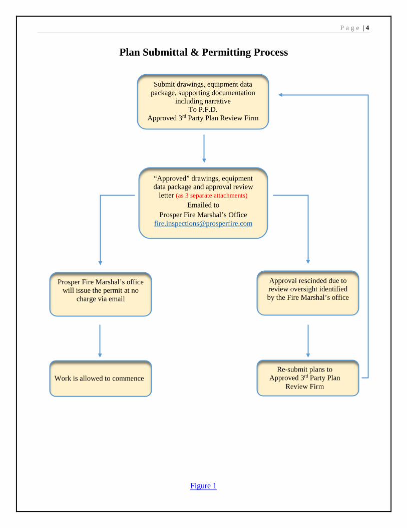
P a g e | 15
Plan Review & Record Drawings Stamp
Figure 3i

P a g e | 16
Fire Alarm Control Unit Battery Calculation Table
Figure 4

P a g e | 17
Voltage Drop Calculation Table
Figure 5
P a g e | 18
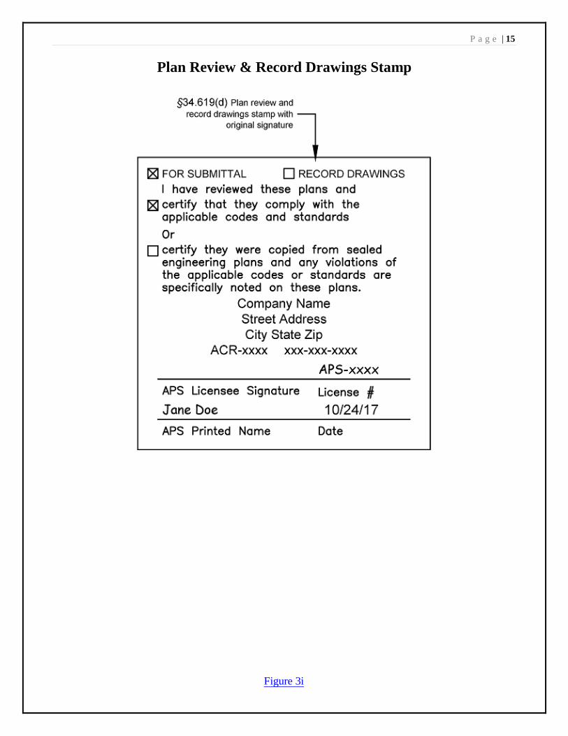
Other Resources for Guidance The following assist to establish clarity with the minimum compliance requirements for the installation and modification of fire alarm systems as prescribed by national codes & standards, state regulations and as adopted by local ordinance. Please Note: Links to this information are under the “Important Website Links” on the Fire Marshal’s Website Page @ www.prospertx.gov/fire-department/fire-marshal
Texas Insurance Code Chapter 6002 (formerly Article 5.43-2) Fire Detection and Alarm Device Installation and 28 TAC §§ 34.600 The Fire Alarm Rules - summer 2016
Sec. 6002.003. Effect on Local Regulation
§34.607. Adopted Standards
§34.611. Licenses and Approvals
§34.616. Sales, Installation, and Service (b)(1), (4)
§34.617. Certification
§34.618. Installation Inspections
§34.619. Fire Alarm and Detection System Plans and Record Drawings
§34.620. Installation Labels
§34.622. Inspection/Test Labels
SF-035 – Fire Alarm Installation Certificate
SF-229 – Work Permitted by Type of License
International Fire Code, 2012 Edition
Prefaceo Introductiono Developmento Adoptiono Maintenance
Chapter 1 – Scope and Administration
Chapter 9 – Fire Protection Systems
Chapter 80 – Referenced Standards
NFPA 72, Most currently published edition
Chapter 1 – Administration
Chapter 7 – Documentation
Chapter 10 – Fundamentals
Chapter 14 – Inspection, Testing & Maintenance
Town of Prosper Ordinances/Amendments 14-51, Dated July 22, 2014
Figure 6

P a g e | 19
Fire-Alarm System Guidelines Identified in the Prosper Amendments All alarm systems new or replacement shall be addressable. Alarm systems serving more than 20 smoke detectors shall be analog addressable. All alarm systems, new or replacement, shall transmit alarm, supervisory and trouble signals descriptively to the approved supervising station, remote supervisory station or proprietary supervising station as defined in the most currently published edition of NFPA 72, with the correct device designation and location of addressable device identification. Alarms shall not be permitted to be transmitted as a General Alarm or Zone condition. Addressable and analog systems shall contain alarm histories for the past 100 events. All fire alarm systems shall be installed in such a manner that a failure of any single initiating device or single open in an initiating circuit conductor will not interfere with the normal operation of other such devices. All signaling line circuits (SLC) shall be installed in such a way that a single open will not interfere with the operation of any addressable devices (Class A). Outgoing and return SLC conductors shall be installed in accordance with current NFPA 72 requirements for Class A circuits and shall have a minimum of four feet separation horizontal and one foot vertical between supply and return circuit conductors. The initiating device circuit (IDC) from an addressable input (monitor) module may be wired Class B, provided the distance from the addressable module to the initiating device is ten feet or less. Where the fire-alarm control panel is not visible from the front (main) entry, a remote annunciator shall be located at the entry and in the sprinkler riser room. A sign shall be provided to identify the Main Panel location. All fire alarm wire jacketing shall be Red in color, however utilizing color striping for circuit designation is acceptable as long as the base jacket is Red in color. Systems shall be restorable without the use of a code or any special knowledge. This can be accomplished through the use of buttons or switches located at the remote annunciator or main control panel. The main power shall be from a dedicated circuit. The location of the branch circuit disconnecting means shall be permanently identified at the control unit and at the power source. For fire alarm and/or signaling systems, the circuit disconnecting means shall have a red marking. Where a circuit breaker is the disconnecting means, an approved breaker locking device shall be installed. An overcurrent protective device shall be provided in accordance with NFPA 70. Secondary power source utilizing batteries shall be marked with a label of contrasting colors (white background with black numbers/letters). The label shall indicate the month and year of manufacture using the month/year format. Where the battery is not marked with the month/year by the manufacturer, the installer shall obtain the date-code and mark the battery with the month/year of battery manufacture. Battery and voltage-drop calculations, in formats similar to those provided in Figure 5, page 17 and Figure 6, page 18, that include all input values for verification. Where summary or average values are input, the derivation of these values must be provided. All manual fire-alarm pull-boxes shall be of the double-action type and Red in color. Occupant notification in accordance with this section and 907.5 shall be required for all new construction, or existing construction complying with the International Building Code, for renovations to existing buildings, tenant spaces, changes in occupancy, replacement or modification of the existing fire alarm system, or as required by the fire code official, for all buildings or spaces provided with an approved automatic sprinkler system. When required by Section 903.4.2, an exterior audible and visible notification appliance shall be provided on the exterior of the building and shall be located above the remote Fire Department Connection. The notification appliance shall operate on a waterflow alarm only, shall be non- silenceable and shall continue to operate after the panel is silenced on the condition the alarm was a waterflow alarm only. The notification appliance shall be wired from the fire alarm control panel as a dedicated latching circuit. The alarm appliance required on the exterior of the building shall be a weatherproof horn/strobe with a minimum 75 candela strobe rating, installed as close as practicable to the fire department connection. When the project has a remote fire department connection a 2nd weatherproof horn/strobe with a minimum 75 candela strobe rating shall be mounted not less than (7’) seven feet above finished grade above the FDC connection.
Figure 7

P a g e | 20
Elevator Recall and Shunt Trip State and local codes regulate elevator installations. Codes that effect fire safety are summarized in this section.
Elevator recall
Elevator recall shall be from a smoke detector activation in the elevator lobby, or machine room Detectors in elevator lobby and machine rooms shall be smoke type in conditioned spaces and heat
detectors in unconditioned spaces. Elevator machine rooms without fire sprinklers shall contain smoke detector(s) for recall only. Where
the rooms are unconditioned, heat detectors shall be provided (135° to 165°)
Elevator shunt trip:
Passenger elevator shafts and elevator machine rooms are exempt from power shunting when sprinklersuppression is not present. Freight elevator systems and hydraulically operated passenger systems maynot be exempt from this requirement. Please consult ASME Code A17.1-2007/CSA B44-07 Safety Codefor Elevators and Escalators, NFPA 13 and NFPA 72 for further clarity.
Elevator cars shall be provided with a 2-way communication system. The communication system must be connected to either a constantly attended (24 hour) location or to an UL-listed monitoring station.
Fire sprinklers shall not be installed in the top of elevator shafts or in the elevator machine rooms. Exception:
NFPA 13 - 8.15.5.1* Sidewall spray sprinklers shall be installed at the bottom of each elevator hoistway not more than 2 ft. (600 mm) above the floor of the pit. NFPA 13 - 8.15.5.2. The sprinkler required at the bottom of the elevator hoistway by 8.15.5.1 shall not be required for enclosed, noncombustible elevator shafts that do not contain combustible hydraulic fluids.
NFPA 72 - 21.3.7* When sprinklers are required in elevator hoistway’s by other codes or standards, fire alarm initiating devices shall be installed to initiate elevator recall in accordance with 2.27.3.2.1(c) of ANSI/ASME A.17.1/CSA B44, Safety Code for Elevators and Escalators, and the following shall apply:
(1) Where sprinklers are located above the lowest level of recall, the fire detection device shall belocated at the top of the hoistway.(2) Where sprinklers are located in the bottom of the hoistway (the pit), fire detection device(s) shallbe installed in the pit in accordance with Chapter 17.(3) Outputs to the elevator controller(s) shall comply with 21.3.13.
TDLR §74.100. Technical Requirements--ASME and ASCE Codes. (a) The commission adopts the standards for the installation, maintenance, repair, replacement, alteration,testing, operation, and inspection of equipment that are contained in the following codes:
(1) ASME Code A17.1-2007/CSA B44-07 as amended in subsection (b)(2) ASME Code A17.3-2002(3) ASME Code A18.1-2005; and(4) ASCE Code 21.
Chapter 74, Elevators, Escalators and Related Equipment Page 17-R February 15, 2016
Figure 8

P a g e | 21
Example Device Wiring & Installation Diagrams NFPA 72 - 7.4.8 Typical wiring diagrams shall be provided for all initiating devices, notification appliances, remote indicators, annunciators, remote test stations, and end-of-line and power supervisory devices.

P a g e | 22
Example Device Wiring & Installation Diagrams continued
NFPA 72 - 7.4.8 Typical wiring diagrams shall be provided for all initiating devices, notification appliances, remote indicators, annunciators, remote test stations, and end-of-line and power supervisory devices
Example Installation Diagrams

P a g e | 23
Example Installation Diagrams continued

P a g e | 24
Example Installation Diagrams continued
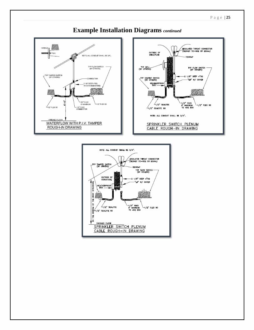
P a g e | 25
Example Installation Diagrams continued

P a g e | 26
NFPA Supervising Station Communication Methods The Town of Prosper recognizes the rapidly retreating support of traditional analog copper based telephone communications methods in favor of newer transmission technologies with their attendant advances in communication capability. In consideration of the impact these advances must have on supervising station fire alarm system communication capabilities now and into the future, the Town of Prosper embraces and promotes the use of listed equipment using alternate communication methods described in chapter 26 of NFPA72 2013-2016 editions.
All methods of communications between the protected premises and a Listed/Approved Supervising Station are accepted in the Town of Prosper as long as they comply with:
• Federal Communications Commission Rules & Regulations as applicable• The manufacturers product as Listed and/or F.M. Approved for such Services• If providing a “Performance Based Design”, it must compliant with all of the above, reviewed and
approved by a Registered Fire Protection Engineer and Acceptable to the A.H.J.• Compatibility between the manufactured product and the supervising station
If you require further clarification please consult and provide this document to your registered Alarm Planning Superintendent (APS), registered Fire Protection Engineer (FPE), manufacturers’ product or the third party supervising station representative.
FCC Ruling FCC ruling 14-5A1 dated 01-30-2014 established regulations that will accommodate the nation’s telephone service providers to begin the phasing out of hard wire (copper) telephone lines (POTS) and Publically Switched Telephone Networks. Accordingly; the current edition of NFPA 72 recognizes this action and has established restrictive methods of communications utilizing a Digital Alarm Communications System (DACT). Please reference NFPA 72, Chapter 26, section 26.6.3.2 Digital Alarm Communicator Systems for clarity.
Further Clarification Excerpts from NFPA 72, 2016 Edition Handbook National Fire Alarm and Signaling Code Handbook, 2016 Edition
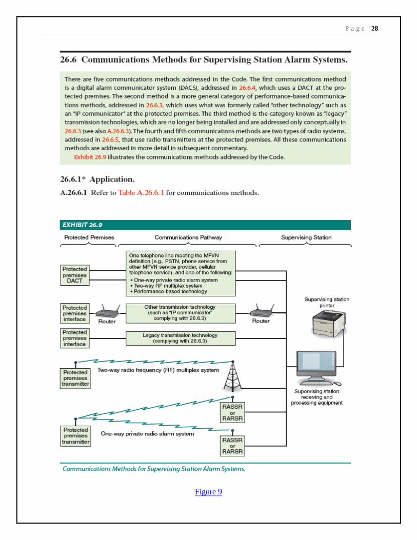
26.6 Communications Methods for Supervising Station Alarm Systems.
There are five communications methods addressed in the Code. The first communications method is a digital alarm communicator system (DACS), addressed in 26.6.4, which uses a DACT at the protected premises. The second method is a more general category of performance-based communications methods, addressed in 26.6.3, which uses what was formerly called “other technology” such as an “IP communicator” at the protected premises. The third method is the category known as “legacy” transmission technologies, which are no longer being installed and are addressed only conceptually in 26.6.3 (See also A.26.6.3). The fourth and fifth communications methods are two types of radio systems, addressed in 26.6.5, that use radio transmitters at the protected premises. All these communications methods are addressed in more detail in subsequent commentary.
Exhibit 26.9 illustrates the communications methods addressed by the Code.
26.6.1* Application.
26.6.4.1.4 Transmission Channels.
(A) A system employing a DACT shall employ one telephone line (number). In addition, one of the followingtransmission means shall be employed:
(1) One-way private radio alarm system(2) Two-way RF multiplex system(3) Transmission means complying with 26.6.3
P a g e | 27
NFPA Supervising Station Communication Methods continued Exception: Where access to two technologies in the preceding list is not available at the protected premises, with the approval of the authority having jurisdiction, a telephone line (number) shall be permitted to be used as the second transmission means. Each DACT shall be programmed to call a second DACR line (number) when the signal transmission sequence to the first called line (number) is unsuccessful. The DACT shall be capable of selecting the operable means of transmission in the event of failure of the other means. Where two telephone lines (numbers) are used, it shall be permitted to test each telephone line (number) at alternating 6-hour intervals.
NFPA 72 - Commentary
The purpose of 26.6.4.1.4 is to provide the DACT with two reasonably reliable means of connecting to the DACR. Note that the Code has no jurisdiction over utility-provided services such as telephone services. Thus, the Code must rely on the traditionally accepted inherent reliability of all such utility provided services. See also the commentary and the Closer Look feature following A.26.6.4.1.1.
Due to the decreased reliability of both traditional and MFVN (Managed Facilities-Based Voice Network) -based PSTNs (Public Switching Telephone Networks), this requirement was revised for the 2013 edition of the Code to no longer permit the use of a second telephone line (number) as the second transmission means for a DACT. Several of the other choices available in previous editions of the Code for the second transmission means were also removed, either because they are no longer available or were never actually used, such as derived local channel, integrated services digital network (ISDN), and private microwave radio. The traditional cellular telephone service that had to dial a number is also no longer permitted. However, digital cellular radio utilizing ubiquitous 2G, 3G, and 4G wireless networks is capable of meeting the performance-based requirements of 26.6.3.
P a g e | 28
Figure 9
P a g e | 29
Town of Prosper, Texas Ordinance No. 14- 51 Fire Alarm Only
(Visit www.prospertx.gov/fire-department/fire-marshal/ for a complete copy of our amendments)
Section 907.1.4 shall be added to read as follows:
907.1.4. Design Standards. All alarm systems new or replacement shall be addressable. Alarm systems serving more than 20 smoke detectors shall be analog addressable. Riser rooms shall be equipped with an annunciator panel.
Exception: Existing systems need not comply unless the total building remodel or expansion initiated after the effective date of this code, as adopted, exceeds 30% of the building. When cumulative building remodel or expansion exceeds 50% of the building, must comply within 18 months of permit application.
Section 907.2.1 shall be amended to read as follows:
907.2.1 Group A. A manual fire alarm system that activates the occupant notification system in accordance with Section 907.6 shall be installed in Group “A” occupancies having an occupant load of 300 or more persons or more than 100 persons above or below the lowest level of exit discharge. Portions of Group E occupancies occupied for assembly purposes shall be provided with a fire alarm system as required for the Group E occupancy.
Activation of fire alarm notification appliances shall:
1. Cause illumination of the means of egress with light of not less than 1 foot-candle (11 lux) at the walkingsurface level, and2. Stop any conflicting or confusing sounds and visual distractions.
Section 907.2.3 shall be amended to read as follows:
907.2.3 Group E. A manual fire alarm system that activates the occupant notification system in accordance with Section 907.6 shall be installed in Group E educational occupancies. When automatic sprinkler systems or smoke detectors are installed, such systems or detectors shall be connected to the building fire alarm system. An approved smoke detection system shall be installed in Group E day care occupancies. Unless separated by a minimum of one hundred feet (100') of open space, all buildings, whether portable buildings or the main building, will be considered one building for alarm occupant load consideration and interconnection of alarm systems.
Section 907.2.3 shall be amended to amend Exception 1 and to add
Exception 1.1 to read as follows:
Exceptions: 1. A manual fire alarm system is not required in Group E educational and day care occupancies with anoccupant load of less than 50 when provided with an approved automatic sprinkler system.1.1. Residential In-Home day care with not more than (12) children may use interconnected single station detectors in all habitable rooms. For care of more than five children 2 ½ or less years of age, see Section 907.2.6.)
Section 907.2.13, Exception 3 shall be amended to read as follows:
Open air portions of buildings with an occupancy in Group A-5 in accordance with Section 303.1 of the International Building Code; however, this exception does not apply to accessory uses including but not limited to sky boxes, restaurants and similarly enclosed areas.
Section 907.4.2.7 shall be added to read as follows:
Section 907.4.2.7 Type. Manual alarm initiating devices shall be an approved Red, double action type.

P a g e | 30
Town of Prosper, Texas Ordinance No. 14- 51 continued
Fire Alarm Only Section 907.6.1.1 shall be added to read as follows:
907.6.1.1 Wiring Installation. All fire alarm systems shall be installed in such a manner that a failure of any single initiating device or single open in an initiating circuit conductor will not interfere with the normal operation of other such devices. All signaling line circuits (SLC) shall be installed in such a way that a single open will not interfere with the operation of any addressable devices (Class A). Outgoing and return SLC conductors shall be installed in accordance with NFPA 72 requirements for Class A circuits and shall have a minimum of four feet separation horizontal and one foot vertical between supply and return circuit conductors. The initiating device circuit (IDC) from an addressable input (monitor) module may be wired Class B, provided the distance from the addressable module to the initiating device is ten feet or less. All fire alarm wire jacketing shall be red in color.
Section 907.5.3 shall be added to read as follows:
Occupant notification in accordance with this section and 907.5 shall be required for all new construction, or existing construction complying with the International Building Code, for renovations to existing buildings, tenant spaces, changes in occupancy, replacement or modification of the existing fire alarm system, or as required by the fire code official, for all buildings or spaces provided with an approved automatic sprinkler system.
Section 907.6.6 shall be added to read as follows:
907.6.6 Waterflow Notification. When required by Section 903.4.2, an exterior audible and visible notification appliance shall be provided on the exterior of the building and shall be located above the Fire Department Connection. The notification appliance shall operate on a waterflow alarm only, shall be non- silenceable and shall continue to operate after the panel is silenced on the condition the alarm was a waterflow alarm only.
The notification appliance shall be wired from the fire alarm control panel as a dedicated latching circuit. Minimum candela rating for the notification appliance shall be 75 (cd) candela.
Section 903.4.2 shall be amended to add a second paragraph to read as follows:
The alarm appliance required on the exterior of the building shall be a weatherproof horn/strobe notification appliance with a minimum 75 candela strobe rating, installed as close as practicable to the fire department connection.
Section 907.6.5.3 shall be added to read as follows:
907.6.5.3 Communication requirements. All alarm systems, new or replacement, shall transmit alarm, supervisory and trouble signals descriptively to the approved supervising station, remote supervisory station or proprietary supervising station as defined in NFPA 72, with the correct device designation and location of addressable device identification. Alarms shall not be permitted to be transmitted as a General Alarm or Zone condition.
Section 907.10 shall be added to read as follows:
907.10. Fire extinguishing systems. Automatic fire- extinguishing systems shall be connected to the building fire alarm system where a fire alarm system is required by another section of this code or is otherwise installed.