Fire Alarm Panels - Safelincs · Fire Alarm Panels Product Manual The operation and functions...
74
www.advancedco.com Fire Alarm Panels Product Manual The operation and functions described in this manual are available from Software Version 5000-050-04 onwards.
Transcript of Fire Alarm Panels - Safelincs · Fire Alarm Panels Product Manual The operation and functions...

www.advancedco.com
Fire Alarm Panels
Product Manual
The operation and functions described in this manual are available from Software Version 5000-050-04 onwards.
www.advancedco.com
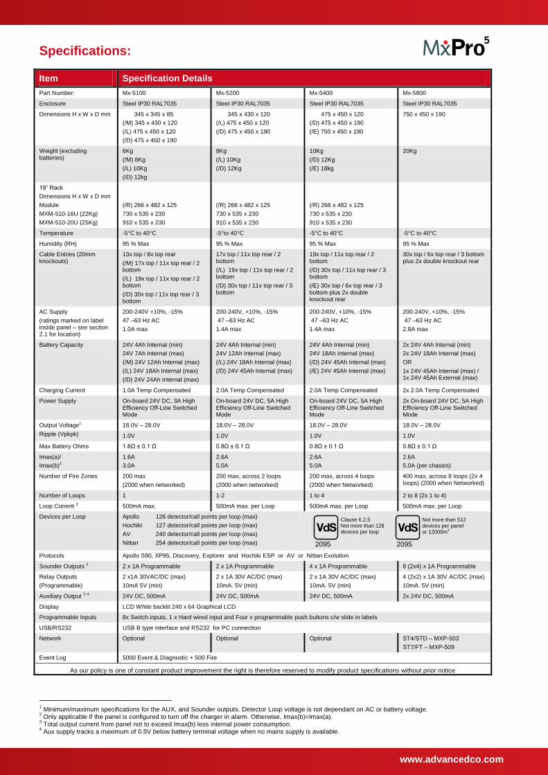
Specifications:
Item Specification Details
Part Number: Mx-5100 Mx-5200 Mx-5400 Mx-5800
Enclosure Steel IP30 RAL7035 Steel IP30 RAL7035 Steel IP30 RAL7035 Steel IP30 RAL7035
Dimensions H x W x D mm 345 x 345 x 85
(/M) 345 x 430 x 120
(/L) 475 x 450 x 120
(/D) 475 x 450 x 190
345 x 430 x 120
(/L) 475 x 450 x 120
(/D) 475 x 450 x 190
475 x 450 x 120
(/D) 475 x 450 x 190
(/E) 750 x 450 x 190
750 x 450 x 190
Weight (excluding batteries)
6Kg
(/M) 8Kg
(/L) 10Kg
(/D) 12kg
8Kg
(/L) 10Kg
(/D) 12Kg
10Kg
(/D) 12Kg
(/E) 18kg
20Kg
19” Rack
Dimensions H x W x D mm
Module
MXM-510-16U (22Kg)
MXM-510-20U (25Kg)
(/R) 266 x 482 x 125
730 x 535 x 230
910 x 535 x 230
(/R) 266 x 482 x 125
730 x 535 x 230
910 x 535 x 230
(/R) 266 x 482 x 125
730 x 535 x 230
910 x 535 x 230
Temperature -5°C to 40°C -5°to 40°C -5°C to 40°C -5°C to 40°C
Humidity (RH) 95 % Max 95 % Max 95 % Max 95 % Max
Cable Entries (20mm knockouts)
13x top / 8x top rear
(/M) 17x top / 11x top rear / 2 bottom
(/L) 19x top / 11x top rear / 2 bottom
(/D) 30x top / 11x top rear / 3 bottom
17x top / 11x top rear / 2 bottom
(/L) 19x top / 11x top rear / 2 bottom
(/D) 30x top / 11x top rear / 3 bottom
19x top / 11x top rear / 2 bottom
(/D) 30x top / 11x top rear / 3 bottom
(/E) 30x top / 6x top rear / 3 bottom plus 2x double knockout rear
30x top / 6x top rear / 3 bottom plus 2x double knockout rear
AC Supply
(ratings marked on label inside panel – see section 2.1 for location)
200-240V +10%, -15%
47 –63 Hz AC
1.0A max
200-240V, +10%, -15%
47 –63 Hz AC
1.4A max
200-240V, +10%, -15%
47 –63 Hz AC
1.4A max
200-240V, +10%, -15%
47 –63 Hz AC
2.8A max
Battery Capacity
24V 4Ah Internal (min)
24V 7Ah Internal (max)
(/M) 24V 12Ah Internal (max)
(/L) 24V 18Ah Internal (max)
(/D) 24V 24Ah Internal (max)
24V 4Ah Internal (min)
24V 12Ah Internal (max)
(/L) 24V 18Ah Internal (max)
(/D) 24V 45Ah Internal (max)
24V 4Ah Internal (min)
24V 18Ah Internal (max)
(/D) 24V 45Ah Internal (max)
(/E) 24V 45Ah Internal (max)
2x 24V 4Ah Internal (min)
2x 24V 18Ah Internal (max)
OR
1x 24V 45Ah Internal (max) / 1x 24V 45Ah External (max)
Charging Current 1.0A Temp Compensated 2.0A Temp Compensated 2.0A Temp Compensated 2x 2.0A Temp Compensated
Power Supply On-board 24V DC, 3A High Efficiency Off-Line Switched Mode
On-board 24V DC, 5A High Efficiency Off-Line Switched Mode
On-board 24V DC, 5A High Efficiency Off-Line Switched Mode
2x On-board 24V DC, 5A High Efficiency Off-Line Switched Mode
Output Voltage1 18.0V – 28.0V 18.0V – 28.0V 18.0V – 28.0V 18.0V – 28.0V
Ripple (Vpkpk) 1.0V 1.0V 1.0V 1.0V
Max Battery Ohms 1.6Ω ± 0.1 Ω 0.8Ω ± 0.1 Ω 0.8Ω ± 0.1 Ω 0.8Ω ± 0.1 Ω
Imax(a)/
Imax(b)2
1.6A
3.0A
2.6A
5.0A
2.6A
5.0A
2.6A
5.0A (per chassis)
Number of Fire Zones 200 max
(2000 when networked)
200 max, across 2 loops
(2000 when networked)
200 max, across 4 loops
(2000 when Networked)
400 max, across 8 loops (2x 4 loops) (2000 when Networked)
Number of Loops 1 1-2 1 to 4 2 to 8 (2x 1 to 4)
Loop Current 3 500mA max. 500mA max. per Loop 500mA max. per Loop 500mA max. per Loop
Devices per Loop Apollo 126 detector/call points per loop (max)
Hochiki 127 detector/call points per loop (max)
AV 240 detector/call points per loop (max)
Nittan 254 detector/call points per loop (max)
V d S
2095
Clause 6.2.5 Not more than 128 devices per loop
V d S
2095
Not more than 512 devices per panel or 12000m2
Protocols Apollo S90, XP95, Discovery, Explorer and Hochiki ESP or AV or Nittan Evolution
Sounder Outputs 3 2 x 1A Programmable 2 x 1A Programmable 4 x 1A Programmable 8 (2x4) x 1A Programmable
Relay Outputs
(Programmable)
2 x1A 30VAC/DC (max)
10mA 5V (min)
2 x 1A 30V AC/DC (max)
10mA. 5V (min)
2 x 1A 30V AC/DC (max)
10mA. 5V (min)
4 (2x2) x 1A 30V AC/DC (max)
10mA. 5V (min)
Auxiliary Output 3 4 24V DC, 500mA 24V DC, 500mA 24V DC, 500mA 2x 24V DC, 500mA
Display LCD White backlit 240 x 64 Graphical LCD
Programmable Inputs 8x Switch inputs, 1 x Hard wired input and Four x programmable push buttons c/w slide in labels
USB/RS232 USB B type interface and RS232 for PC connection
Network Optional Optional Optional ST4/STD – MXP-503
ST7/FT – MXP-509
Event Log 5000 Event & Diagnostic + 500 Fire
As our policy is one of constant product improvement the right is therefore reserved to modify product specifications without prior notice
1 Minimum/maximum specifications for the AUX, and Sounder outputs. Detector Loop voltage is not dependant on AC or battery voltage.
2 Only applicable if the panel is configured to turn off the charger in alarm. Otherwise, Imax(b)=Imax(a).
3 Total output current from panel not to exceed Imax(b) less internal power consumption.
4 Aux supply tracks a maximum of 0.5V below battery terminal voltage when no mains supply is available.
www.advancedco.com
3
Table of Contents Page
1 INTRODUCTION............................................................................................................................................. 6
1.1 STANDARDS ............................................................................................................................................. 6 1.2 CAUTIONS AND WARNINGS ....................................................................................................................... 7 1.3 DESCRIPTION ........................................................................................................................................... 7
1.3.1 5000 Series ........................................................................................................................................ 7 1.3.2 5000V Series...................................................................................................................................... 7 1.3.3 5000N Series ..................................................................................................................................... 7
1.4 EN54 FUNCTIONS .................................................................................................................................... 8 1.5 EN54 OPTIONAL FEATURES WITH REQUIREMENTS .................................................................................... 9 1.6 INSTALLATION APPROVALS ..................................................................................................................... 10
1.6.1 Fire System Installations .................................................................................................................. 10 1.6.2 Wiring Regulations ........................................................................................................................... 10
2 INSTALLATION ............................................................................................................................................ 11
2.1 IDENTIFICATION OF PARTS ...................................................................................................................... 11 2.1.1 5100 ................................................................................................................................................. 11 2.1.2 5200 ................................................................................................................................................. 12 2.1.3 5400 ................................................................................................................................................. 13 2.1.4 5800 ................................................................................................................................................. 13 2.1.5 5000R ............................................................................................................................................... 14
2.2 INSTALLING THE ENCLOSURE .................................................................................................................. 15 2.2.1 Opening the Enclosure Cover .......................................................................................................... 15 2.2.2 Removing the Chassis ..................................................................................................................... 15 2.2.3 Mounting the Enclosure ................................................................................................................... 15 2.2.4 Remounting the Chassis .................................................................................................................. 17 2.2.5 Recommended Cable Routing Arrangement ................................................................................... 18
2.3 LOOP DRIVER INSTALLATION .................................................................................................................. 19 2.3.1 Fitting the cards ............................................................................................................................... 19 2.3.2 Removing a Loop Driver Card ......................................................................................................... 20
2.4 PLUG-IN / PERIPHERAL BUS MODULES .................................................................................................... 20 2.4.1 Routing Interface Card (Plug-In) ...................................................................................................... 20 2.4.2 2-Way Relay Card (Plug-In) ............................................................................................................. 21 2.4.3 Network Card ................................................................................................................................... 21 2.4.4 Peripheral Module Chassis Mounting .............................................................................................. 22 2.4.5 VdS Interface Module Chassis Mounting ......................................................................................... 23
2.4.5.1 Option Relay Card ................................................................................................................................. 23 2.4.5.2 Optional Redundant Ring Controller ...................................................................................................... 23
2.5 WIRING INSTALLATION ............................................................................................................................ 24 2.5.1 AC Mains Wiring .............................................................................................................................. 24
2.5.1.1 Cable Gland ........................................................................................................................................... 24 2.5.2 Battery Installation ........................................................................................................................... 25
2.5.2.1 Small Enclosure ..................................................................................................................................... 25 2.5.2.2 Medium Enclosure ................................................................................................................................. 26 2.5.2.3 Large Enclosure ..................................................................................................................................... 26 2.5.2.4 Deep Enclosure ..................................................................................................................................... 27
2.5.3 Detector Loop Installation ................................................................................................................ 28 2.5.4 Sounder Circuits .............................................................................................................................. 29 2.5.5 Network Interface ............................................................................................................................. 30 2.5.6 Relay Circuits ................................................................................................................................... 31 2.5.7 Auxiliary Supply Output .................................................................................................................... 31 2.5.8 Isolated Peripheral Bus Interface ..................................................................................................... 31 2.5.9 Switch Inputs .................................................................................................................................... 32
2.5.9.1 Base Card .............................................................................................................................................. 32 2.5.9.2 Display Card .......................................................................................................................................... 32
2.5.10 RS232 Interface ........................................................................................................................... 32 2.5.11 USB Interface (Type B) ............................................................................................................... 32 2.5.12 Routing Interface ......................................................................................................................... 33
2.5.12.1 Fire / Fault Routing ................................................................................................................................ 33 2.5.12.2 Fire Protection Routing .......................................................................................................................... 33
2.5.13 VdS Interface ............................................................................................................................... 34
www.advancedco.com 4
2.5.13.1 FAT / FBF Direct Connection ................................................................................................................ 35 2.5.13.2 FAT / FBF Redundant Connection ........................................................................................................ 36 2.5.13.3 FSD Key Deposit Box Connection ......................................................................................................... 36 2.5.13.4 ÜE Fire Routing ..................................................................................................................................... 37 2.5.13.5 Fault Routing ......................................................................................................................................... 37
3 PROGRAMMING ......................................................................................................................................... 38
3.1 INTRODUCTION ...................................................................................................................................... 38 3.1.1 Access Levels ................................................................................................................................. 38 3.1.2 Memory Lock ................................................................................................................................... 38 3.1.3 Navigating through menus .............................................................................................................. 38 3.1.4 Changing Text Descriptions ............................................................................................................ 39 3.1.5 Numeric data entry .......................................................................................................................... 39
3.2 LEVEL 3 MENU FUNCTIONS .................................................................................................................... 40 3.3 RECOMMENDED PROGRAMMING PROCEDURE ......................................................................................... 41
3.3.1 Loops .............................................................................................................................................. 41 3.3.2 Loops – View/Edit ........................................................................................................................... 41
3.3.2.1 State ...................................................................................................................................................... 41 3.3.2.2 Type ...................................................................................................................................................... 42 3.3.2.3 Value ..................................................................................................................................................... 42 3.3.2.4 Zone ...................................................................................................................................................... 42 3.3.2.5 Device Text ........................................................................................................................................... 42 3.3.2.6 Action .................................................................................................................................................... 42 3.3.2.7 Sensitivity .............................................................................................................................................. 43 3.3.2.8 O/P Group ............................................................................................................................................. 45 3.3.2.9 Additional Info ........................................................................................................................................ 45 3.3.2.10 Device Testing ....................................................................................................................................... 45
3.3.3 Loops – Auto Learn ......................................................................................................................... 46 3.3.3.1 Normal Procedure / Initial learn ............................................................................................................. 46 3.3.3.2 Procedure if the Panel finds Devices Missing ........................................................................................ 46 3.3.3.3 Procedure if the Panel finds Devices Added ......................................................................................... 46 3.3.3.4 Procedure if the Panel finds Devices Changed ..................................................................................... 47
3.3.4 Loop – Calibrate .............................................................................................................................. 47 3.3.5 Loop - History .................................................................................................................................. 47 3.3.6 Loop – Meter ................................................................................................................................... 48 3.3.7 Loop – Scope .................................................................................................................................. 48 3.3.8 Zones .............................................................................................................................................. 49 3.3.9 Exit .................................................................................................................................................. 49 3.3.10 Disable ........................................................................................................................................ 49 3.3.11 Enable ......................................................................................................................................... 49 3.3.12 View Options ............................................................................................................................... 50 3.3.13 Passwords .................................................................................................................................. 50 3.3.14 Time and Date ............................................................................................................................ 50 3.3.15 PC Config ................................................................................................................................... 50 3.3.16 EN54-13 ...................................................................................................................................... 51 3.3.17 Setup........................................................................................................................................... 51
3.3.17.1 Network ................................................................................................................................................. 51 3.3.17.2 Panel Zone ............................................................................................................................................ 51 3.3.17.3 Service Number ..................................................................................................................................... 52 3.3.17.4 Service Due Date .................................................................................................................................. 52 3.3.17.5 Trace Logging Mode.............................................................................................................................. 52 3.3.17.6 Detector Blinking ................................................................................................................................... 52 3.3.17.7 Earth Fault Notification .......................................................................................................................... 53 3.3.17.8 Resound ................................................................................................................................................ 53 3.3.17.9 Config Data ........................................................................................................................................... 53
3.3.18 Display ........................................................................................................................................ 54 3.3.19 Panel ........................................................................................................................................... 54
3.3.19.1 AC Fail Delay ........................................................................................................................................ 55 3.3.20 Output Groups ............................................................................................................................ 56
3.3.20.1 Default Output Settings ......................................................................................................................... 56 3.3.20.2 Cause .................................................................................................................................................... 57 3.3.20.3 Style ...................................................................................................................................................... 58 3.3.20.4 Delay ..................................................................................................................................................... 58 3.3.20.5 Mode ..................................................................................................................................................... 58 3.3.20.6 Wait ....................................................................................................................................................... 58 3.3.20.7 Copying Output Settings to Multiple Zones ........................................................................................... 58
www.advancedco.com
5
3.3.21 Investigation Delays .................................................................................................................... 58 3.3.21.1 Overriding Delays at Level 1 .................................................................................................................. 59
3.3.22 Test .............................................................................................................................................. 59 3.3.23 LED Indications............................................................................................................................ 59
4 SERVICE AND MAINTENANCE .................................................................................................................. 60
4.1 MAINTENANCE SCHEDULE ...................................................................................................................... 60 4.1.1 Daily Actions .................................................................................................................................... 60 4.1.2 Monthly Actions ................................................................................................................................ 60 4.1.3 Quarterly Actions ............................................................................................................................. 60 4.1.4 Annual Actions ................................................................................................................................. 60
4.2 REPLACEMENT OF COMPONENTS ............................................................................................................ 61 4.2.1 Batteries ........................................................................................................................................... 61
4.2.1.1 Standby Batteries................................................................................................................................... 61 4.2.2 Liquid Crystal Display ...................................................................................................................... 62 4.2.3 Spares .............................................................................................................................................. 62
5 APPENDICES ............................................................................................................................................... 63
5.1 APPENDIX 1 – FORGOTTEN LEVEL 3 PASSWORD ..................................................................................... 63 5.2 APPENDIX 2 – RECOMMENDED FIRE RATED CABLES................................................................................ 64
5.2.1 Detector Loop Lengths – Apollo, Hochiki and AV ........................................................................... 64 5.2.2 Sounder Circuit Lengths .................................................................................................................. 65 5.2.3 Fire / Fault Routing Circuit Lengths ................................................................................................. 65 5.2.4 Network Cables ................................................................................................................................ 65
5.3 APPENDIX 3 – BATTERY STANDBY CALCULATION CHART ......................................................................... 66 5.4 APPENDIX 4 – CAUSE AND EFFECT PROGRAMMING EXAMPLE .................................................................. 67
5.4.1 Introduction ...................................................................................................................................... 67 5.4.2 Output Groups ................................................................................................................................. 67 5.4.3 Styles ............................................................................................................................................... 67 5.4.4 Output Group Programming ............................................................................................................. 68
5.5 APPENDIX 5 – OTHER USEFUL DOCUMENTS ............................................................................................ 69 5.6 APPENDIX 6 –NETWORK DESIGN PRINCIPLES .......................................................................................... 70
5.6.1 Mandatory Functions ....................................................................................................................... 70 5.6.2 Network Wiring ................................................................................................................................. 70 5.6.3 Parent Functions .............................................................................................................................. 70
5.7 APPENDIX 7 – MX SERIES PRODUCT CAPABILITIES / MAX LIMITS ............................................................. 71

www.advancedco.com 6
1 Introduction
1.1 Standards
Advanced Electronics Ltd declares that the products identified below conform to the essential requirements
specified in the Construction Products Directive 89/106/EEC:
0786-CPD-20952
EN54-2: 1997 +A1:2006 Control and indicating equipment for fire detection and fire alarm systems for buildings Provided options: - Outputs to Fire Alarm Devices - Output to Fire Routing Equipment - Output to Fire Protection Equipment - Output to Fault Routing Equipment - Investigation Delays to Outputs - Dependency on more than one alarm signal - Fault Signals from Points - Disablement of Points - Alarm Counter - Test Condition - Standardised Input / Output
EN54-4: 1997 +A1:2002 +A2:2006 Power supply equipment for fire detection and fire alarm systems for buildings
Mx-5100, Mx-5200, Mx-5400, MX-5800
Mx-5100V, Mx-5200V, Mx-5400V, MX-5800V
Mx-5100N, Mx-5200N, Mx-5400N, MX-5800N
In addition, the products comply with the following:
Low Voltage Directive 2006/95/EC
BS EN60950-1: 2006 Safety of information technology equipment
Electromagnetic Compatibility Directive 2004/108/EC
BS EN55022: 1998 Emissions, Class B
BS EN50130-4: 1996 +A2: 2003 Immunity, Product Family Standard

www.advancedco.com
7
1.2 Cautions and Warnings
STOP
BEFORE INSTALLATION – Refer To the Ratings shown on the label inside
the product and to the ‘Specifications Chart’ in this document.
Please read this manual carefully. If you are unclear on any point DO NOT
proceed. Contact the manufacturer or supplier for clarification and guidance.
Only Trained service personnel should undertake the Installation,
Programming and Maintenance of this equipment.
This product has been designed to comply with the requirements of the Low
Voltage Safety and the EMC Directives. Failure to follow the installation
instructions may compromise its adherence to these standards.
ATTENTION OBSERVE PRECAUTIONS
FOR HANDLING ELECTROSTATIC
SENSITIVE DEVICES
This equipment is constructed with static sensitive components. Observe anti-
static precautions at all times when handling printed circuit boards. Wear an
anti-static earth strap connected to panel enclosure earth point. Before installing
or removing any printed circuit boards remove all sources of power (mains and
battery).
PPCC OONNLLYY
Where you see the “PC Only” symbol, these features can either only be set-up
using the PC Configuration Tool or there are additional options that are only
available via the PC Configuration Tool.
1.3 Description This manual covers the installation, programming and commissioning of the 5000, 5000V & 5000N Series Fire Alarm Control Panels. This manual provides generic programming and installation information – Refer to the appropriate protocol application note for further and specific information for each protocol.
Refer to the User Manual (Document No. 680-166) for details of how to operate the panel.
All panel models are available in a range of enclosure sizes and with a range of alternative optional features.
1.3.1 5000 Series
The 5100 is a Single Loop, Analogue Addressable Fire Alarm Control Panel.
The 5200 is a Two Loop, Analogue Addressable Fire Alarm Control Panel.
The 5400 is a Multiple Loop, Analogue Addressable Fire Alarm Control Panel with provision for up to four loops.
All above models are designed for use with the Apollo (Discovery, Explorer, XP95 and Series 90) and Hochiki (ESP) fire detection devices.
1.3.2 5000V Series
The 5100V is a Single Loop, Analogue Addressable Fire Alarm Control Panel.
The 5200V is a Two Loop, Analogue Addressable Fire Alarm Control Panel.
The 5400V is a Multiple Loop, Analogue Addressable Fire Alarm Control Panel with provision for up to four loops.
All above models are designed for use with the Advanced (AV) fire detection devices.
1.3.3 5000N Series
The 5100N is a Single Loop, Analogue Addressable Fire Alarm Control Panel.
The 5200N is a Two Loop, Analogue Addressable Fire Alarm Control Panel.
The 5400N is a Multiple Loop, Analogue Addressable Fire Alarm Control Panel with provision for up to four loops.
All above models are designed for use with the Nittan Evolution fire detection devices.
www.advancedco.com 8
Install the panel, detection loops, sounder circuits, etc. in accordance with the instructions in Section 2 and then program the operation in accordance with the instructions detailed in Section 3.
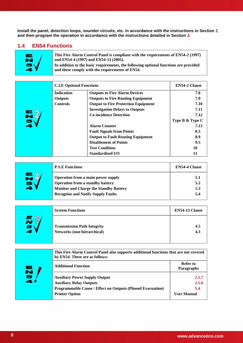
1.4 EN54 Functions
This Fire Alarm Control Panel is compliant with the requirements of EN54-2 (1997)
and EN54-4 (1997) and EN54-13 (2005).
In addition to the basic requirements, the following optional functions are provided
and these comply with the requirements of EN54.
C.I.E Optional Functions EN54-2 Clause
Indication
Outputs
Controls
Outputs to Fire Alarm Devices
Outputs to Fire Routing Equipment
Output to Fire Protection Equipment
Investigation Delays to Outputs
Co-incidence Detection
Alarm Counter
Fault Signals from Points
Output to Fault Routing Equipment
Disablement of Points
Test Condition
Standardised I/O
7.8
7.9
7.10
7.11
7.12
Type B & Type C
7.13
8.3
8.9
9.5
10
11
P.S.E Functions EN54-4 Clause
Operation from a main power supply
Operation from a standby battery
Monitor and Charge the Standby Battery
Recognise and Notify Supply Faults
5.1
5.2
5.3
5.4
System Functions EN54-13 Clause
Transmission Path Integrity
Networks (non hierarchical)
4.5
4.3
This Fire Alarm Control Panel also supports additional functions that are not covered
by EN54. These are as follows:
Additional Function Refer to
Paragraphs
Auxiliary Power Supply Output
Auxiliary Relay Outputs
Programmable Cause / Effect on Outputs (Phased Evacuation)
Printer Option
2.5.7
2.5.6
5.4
User Manual
www.advancedco.com
9
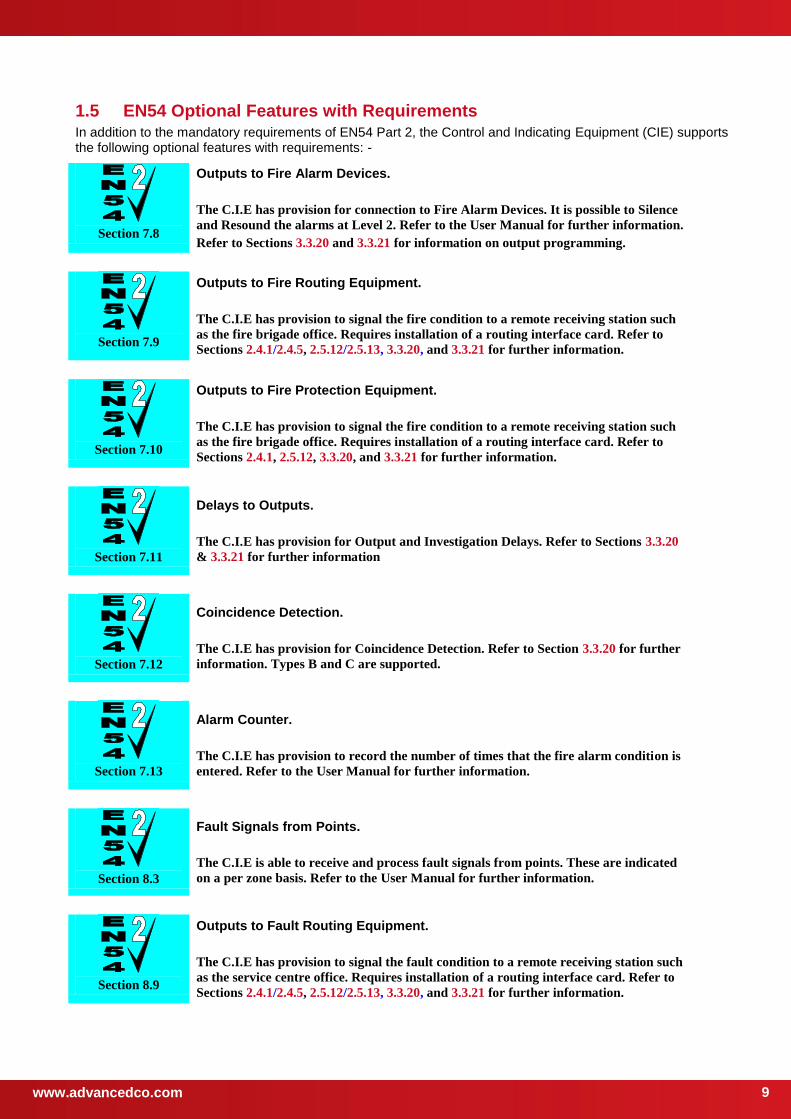
1.5 EN54 Optional Features with Requirements In addition to the mandatory requirements of EN54 Part 2, the Control and Indicating Equipment (CIE) supports the following optional features with requirements: -
Section 7.8
Outputs to Fire Alarm Devices.
The C.I.E has provision for connection to Fire Alarm Devices. It is possible to Silence
and Resound the alarms at Level 2. Refer to the User Manual for further information.
Refer to Sections 3.3.20 and 3.3.21 for information on output programming.
Section 7.9
Outputs to Fire Routing Equipment.
The C.I.E has provision to signal the fire condition to a remote receiving station such
as the fire brigade office. Requires installation of a routing interface card. Refer to
Sections 2.4.1/2.4.5, 2.5.12/2.5.13, 3.3.20, and 3.3.21 for further information.
Section 7.10
Outputs to Fire Protection Equipment.
The C.I.E has provision to signal the fire condition to a remote receiving station such
as the fire brigade office. Requires installation of a routing interface card. Refer to
Sections 2.4.1, 2.5.12, 3.3.20, and 3.3.21 for further information.
Section 7.11
Delays to Outputs.
The C.I.E has provision for Output and Investigation Delays. Refer to Sections 3.3.20
& 3.3.21 for further information
Section 7.12
Coincidence Detection.
The C.I.E has provision for Coincidence Detection. Refer to Section 3.3.20 for further
information. Types B and C are supported.
Section 7.13
Alarm Counter.
The C.I.E has provision to record the number of times that the fire alarm condition is
entered. Refer to the User Manual for further information.
Section 8.3
Fault Signals from Points.
The C.I.E is able to receive and process fault signals from points. These are indicated
on a per zone basis. Refer to the User Manual for further information.
Section 8.9
Outputs to Fault Routing Equipment.
The C.I.E has provision to signal the fault condition to a remote receiving station such
as the service centre office. Requires installation of a routing interface card. Refer to
Sections 2.4.1/2.4.5, 2.5.12/2.5.13, 3.3.20, and 3.3.21 for further information.

www.advancedco.com 10
Section 9.5
Disablement of Points.
The C.I.E has provision for enabling and disabling signals from points. Refer to the
User Manual for further information.
Section 10
Test Condition.
The C.I.E has provision for testing the installation on a per zone basis. Refer to the
User Manual for further information.
Section 11
Standardised Input / Output interface.
Standardised I/O interfaces are supported over the Ad-Net Network.
1.6 Installation Approvals
1.6.1 Fire System Installations
The panel must be installed and configured for operation in accordance with these instructions and the applicable code of practice or national standard regulations for fire systems installation (for example BS5839-1: 2002) appropriate to the country and location of the installation.
1.6.2 Wiring Regulations
The panel and system must be installed in accordance with these instructions and the applicable wiring codes and regulations (for example BS7671) appropriate to the country and location of the installation.
www.advancedco.com
11
2 Installation
2.1 Identification of Parts
The following diagrams show the major parts of the panels.
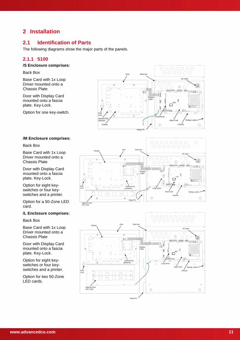
2.1.1 5100
/S Enclosure comprises:
Back Box
Base Card with 1x Loop Driver mounted onto a Chassis Plate
Door with Display Card mounted onto a fascia plate. Key-Lock.
Option for one key-switch.
WARNING: HIGH VOLTAGE INSIDE
DO NOT REMOVE COVER
No Serviceable Parts Inside
Display
Loop Driver
Base Card
Chassis
Door Back box
Hinge Pin
Display Cable
AC Input
Optional Key Switches
Door Lock
Ratings Label
/M Enclosure comprises:
Back Box
Base Card with 1x Loop Driver mounted onto a Chassis Plate
Door with Display Card mounted onto a fascia plate. Key-Lock.
Option for eight key-switches or four key-switches and a printer.
Option for a 50-Zone LED card.
WARNING: HIGH VOLTAGE INSIDE
DO NOT REMOVE COVER
No Serviceable Parts Inside
Display
Loop Driver
Base Card
Chassis
Door Back box
Hinge Pin
Display Cable
AC Input
Optional Zone LED Card
Optional Key Switches
Door Lock
Ratings Label
/L Enclosure comprises:
Back Box
Base Card with 1x Loop Driver mounted onto a Chassis Plate
Door with Display Card mounted onto a fascia plate. Key-Lock.
Option for eight key-switches or four key-switches and a printer.
Option for two 50-Zone LED cards.
WARN ING: HIGH VOLTAGE IN SID E
DO NOT REM OVE C OVER No Ser viceabl e Parts Inside
Display
Loop Driver
Base Card
Chassis
Door Back box
Hinge Pin
AC Input
Optional Zone LED Cards
Optional Key Switches
Door Lock
Display Cable
Ratings Label
www.advancedco.com 12
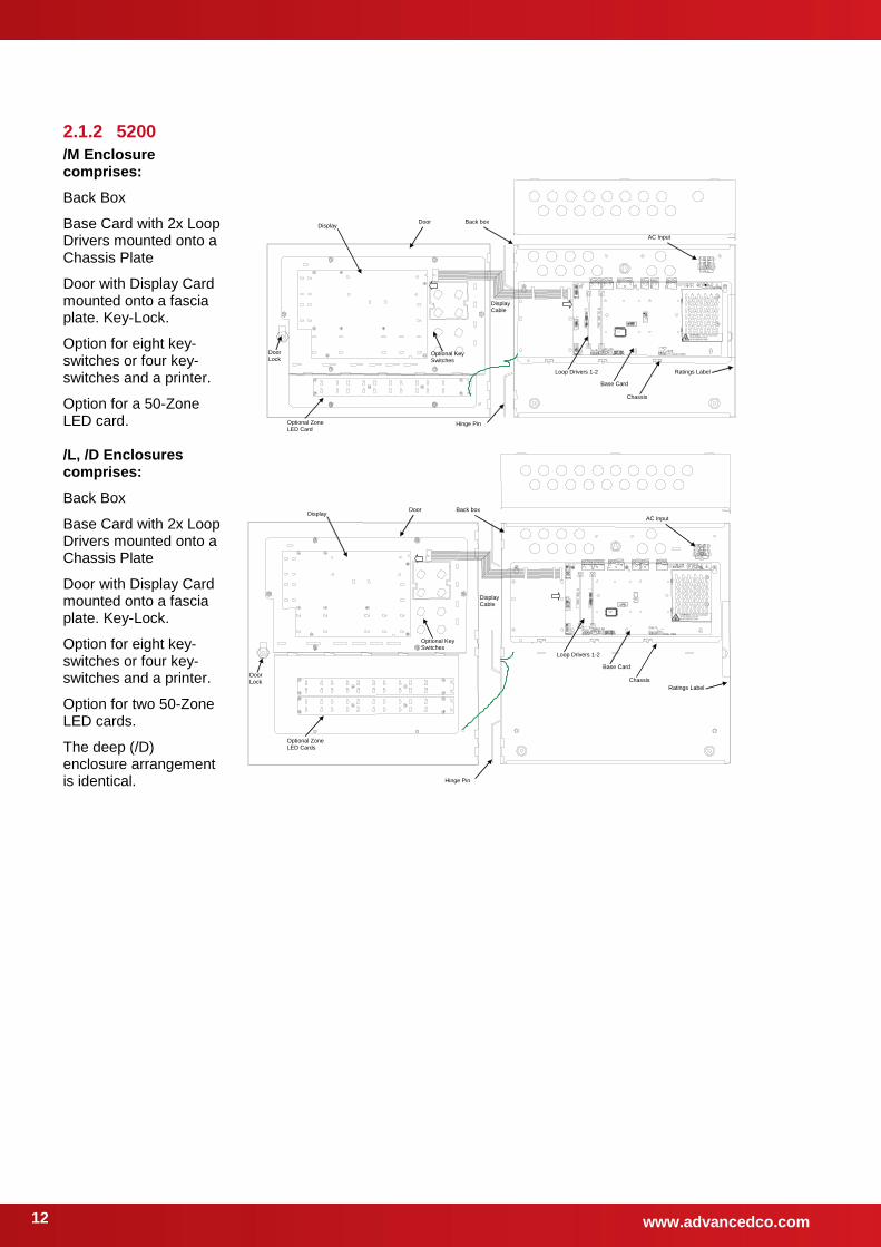
2.1.2 5200
/M Enclosure comprises:
Back Box
Base Card with 2x Loop Drivers mounted onto a Chassis Plate
Door with Display Card mounted onto a fascia plate. Key-Lock.
Option for eight key-switches or four key-switches and a printer.
Option for a 50-Zone LED card.
WARNING: HIGH VOLTAGE INSIDE
DO NOT REMOVE COVER
No Serviceable Parts Inside
Display
Loop Drivers 1-2
Base Card
Chassis
Door Back box
Hinge Pin
Display Cable
AC Input
Optional Zone LED Card
Optional Key Switches
Door Lock
Ratings Label
/L, /D Enclosures comprises:
Back Box
Base Card with 2x Loop Drivers mounted onto a Chassis Plate
Door with Display Card mounted onto a fascia plate. Key-Lock.
Option for eight key-switches or four key-switches and a printer.
Option for two 50-Zone LED cards.
The deep (/D) enclosure arrangement is identical.
WARNING: HIGH VOLTAGE INSIDE
DO NOT REMOVE COVER
No Serviceable Parts Inside
Display
Loop Drivers 1-2
Base Card
Chassis
Door Back box
Hinge Pin
AC Input
Optional Zone LED Cards
Optional Key Switches
Door Lock
Display Cable
Ratings Label

www.advancedco.com
13
2.1.3 5400
/L, /D Enclosures comprises:
Back Box
Base Card with 1-4 Loop Drivers mounted onto a Chassis Plate
Door with Display Card mounted onto a fascia plate. Key-Lock.
Option for eight key-switches or four key-switches and a printer.
Option for two 50-Zone LED cards.
The deep (/D) enclosure arrangement is identical.
WARNING: HIGH VOLTAGE INSID
DO NOT REMOVE COVER
No Serviceable Parts Inside
Display
Loop Drivers 1-4
Base Card
Chassis
Door Back box
Hinge Pin
AC Input
Optional Zone LED Cards
Optional Key Switches
Door Lock
Display Cable
Ratings Label
2.1.4 5800
/E Enclosures comprises:
Back Box
Door with Display Card mounted onto a fascia plate. Key-Lock (2).
Option for eight key-switches or four key-switches and a printer.
Option for MXP-513-XXX LED cards fitted to door.
The MX-5800 consists of two independent systems comprising of 4-LP Base Cards and Display Cards (only one display is normally visible) and each system capable of supporting 512 detection devices.
Network cards are fitted as standard and wired internally. Additional information on networking is detailed in document 680-502.
For redundancy of indications and controls, install an MX-5030 Remote Terminal.
For redundancy of parent functions (i.e. Fire Alarm Routing, Fire Brigade Terminals, etc.) install these with redundant connection from each chassis using the appropriate interfaces.
AC MAINS Input Filter Card
Chassis #1 (Mx-5400 & Mx-5800)
Chassis #2 (Mx-5800 Only)
Display #1
Display #2
Optional LED Indicators
Optional Mounting positions for Peripheral Bus Module OR for IFAM Redundant Ring Controller
Ratings Label
MX-5400E arrangement is identical but without Chassis #2 and Display #2.
For more information see document 680-208
www.advancedco.com 14
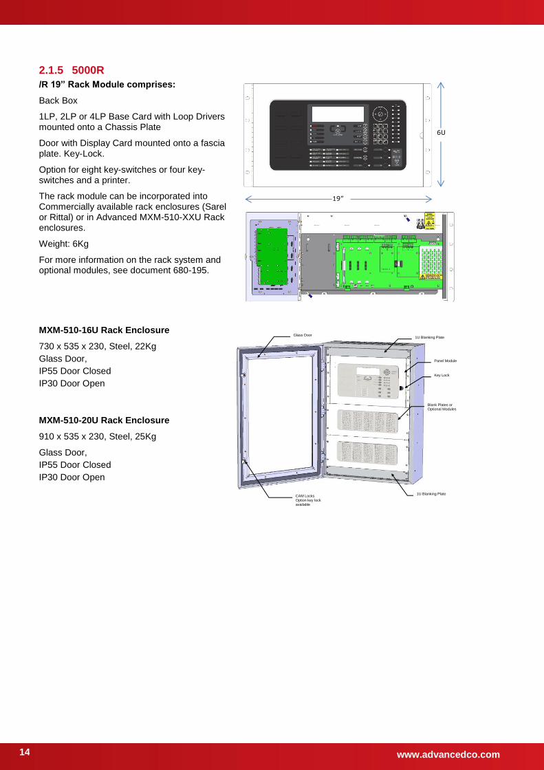
2.1.5 5000R
/R 19” Rack Module comprises:
Back Box
1LP, 2LP or 4LP Base Card with Loop Drivers mounted onto a Chassis Plate
Door with Display Card mounted onto a fascia plate. Key-Lock.
Option for eight key-switches or four key-switches and a printer.
The rack module can be incorporated into Commercially available rack enclosures (Sarel or Rittal) or in Advanced MXM-510-XXU Rack enclosures.
Weight: 6Kg
For more information on the rack system and optional modules, see document 680-195.
MXM-510-16U Rack Enclosure
730 x 535 x 230, Steel, 22Kg
Glass Door,
IP55 Door Closed
IP30 Door Open
MXM-510-20U Rack Enclosure
910 x 535 x 230, Steel, 25Kg
Glass Door,
IP55 Door Closed
IP30 Door Open
1U Blanking Plate
Panel Module
Blank Plates or Optional Modules
Glass Door
1U Blanking Plate CAM Locks Option key lock available
Key Lock
6U
19”
www.advancedco.com
15
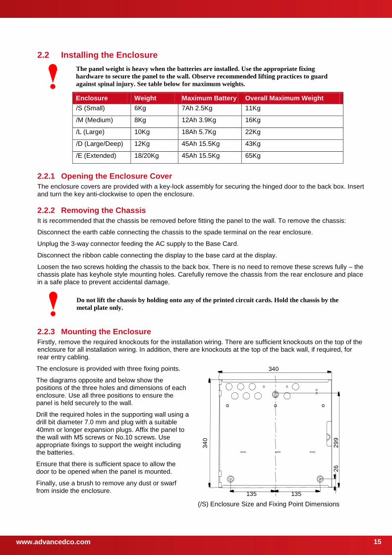
2.2 Installing the Enclosure
The panel weight is heavy when the batteries are installed. Use the appropriate fixing
hardware to secure the panel to the wall. Observe recommended lifting practices to guard
against spinal injury. See table below for maximum weights.
Enclosure Weight Maximum Battery Overall Maximum Weight
/S (Small) 6Kg 7Ah 2.5Kg 11Kg
/M (Medium) 8Kg 12Ah 3.9Kg 16Kg
/L (Large) 10Kg 18Ah 5.7Kg 22Kg
/D (Large/Deep) 12Kg 45Ah 15.5Kg 43Kg
/E (Extended) 18/20Kg 45Ah 15.5Kg 65Kg
2.2.1 Opening the Enclosure Cover
The enclosure covers are provided with a key-lock assembly for securing the hinged door to the back box. Insert and turn the key anti-clockwise to open the enclosure.
2.2.2 Removing the Chassis
It is recommended that the chassis be removed before fitting the panel to the wall. To remove the chassis:
Disconnect the earth cable connecting the chassis to the spade terminal on the rear enclosure.
Unplug the 3-way connector feeding the AC supply to the Base Card.
Disconnect the ribbon cable connecting the display to the base card at the display.
Loosen the two screws holding the chassis to the back box. There is no need to remove these screws fully – the chassis plate has keyhole style mounting holes. Carefully remove the chassis from the rear enclosure and place in a safe place to prevent accidental damage.
Do not lift the chassis by holding onto any of the printed circuit cards. Hold the chassis by the
metal plate only.
2.2.3 Mounting the Enclosure
Firstly, remove the required knockouts for the installation wiring. There are sufficient knockouts on the top of the enclosure for all installation wiring. In addition, there are knockouts at the top of the back wall, if required, for rear entry cabling.
The enclosure is provided with three fixing points.
The diagrams opposite and below show the positions of the three holes and dimensions of each enclosure. Use all three positions to ensure the panel is held securely to the wall.
Drill the required holes in the supporting wall using a drill bit diameter 7.0 mm and plug with a suitable 40mm or longer expansion plugs. Affix the panel to the wall with M5 screws or No.10 screws. Use appropriate fixings to support the weight including the batteries.
Ensure that there is sufficient space to allow the door to be opened when the panel is mounted.
Finally, use a brush to remove any dust or swarf from inside the enclosure.
340
34
0
29
9
135 135
26
(/S) Enclosure Size and Fixing Point Dimensions
www.advancedco.com 16
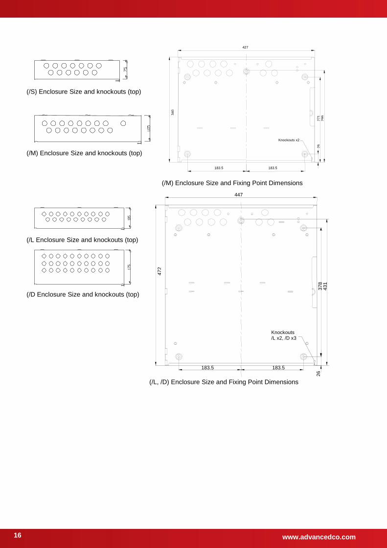
(/S) Enclosure Size and knockouts (top)
(/M) Enclosure Size and knockouts (top)
427
34
0
29
9
26
183.5 183.5
Knockouts x2
27
1
(/M) Enclosure Size and Fixing Point Dimensions
(/L Enclosure Size and knockouts (top)
(/D Enclosure Size and knockouts (top)
447
47
2
43
1
26 183.5 183.5
Knockouts /L x2, /D x3
37
8
(/L, /D) Enclosure Size and Fixing Point Dimensions
www.advancedco.com
17
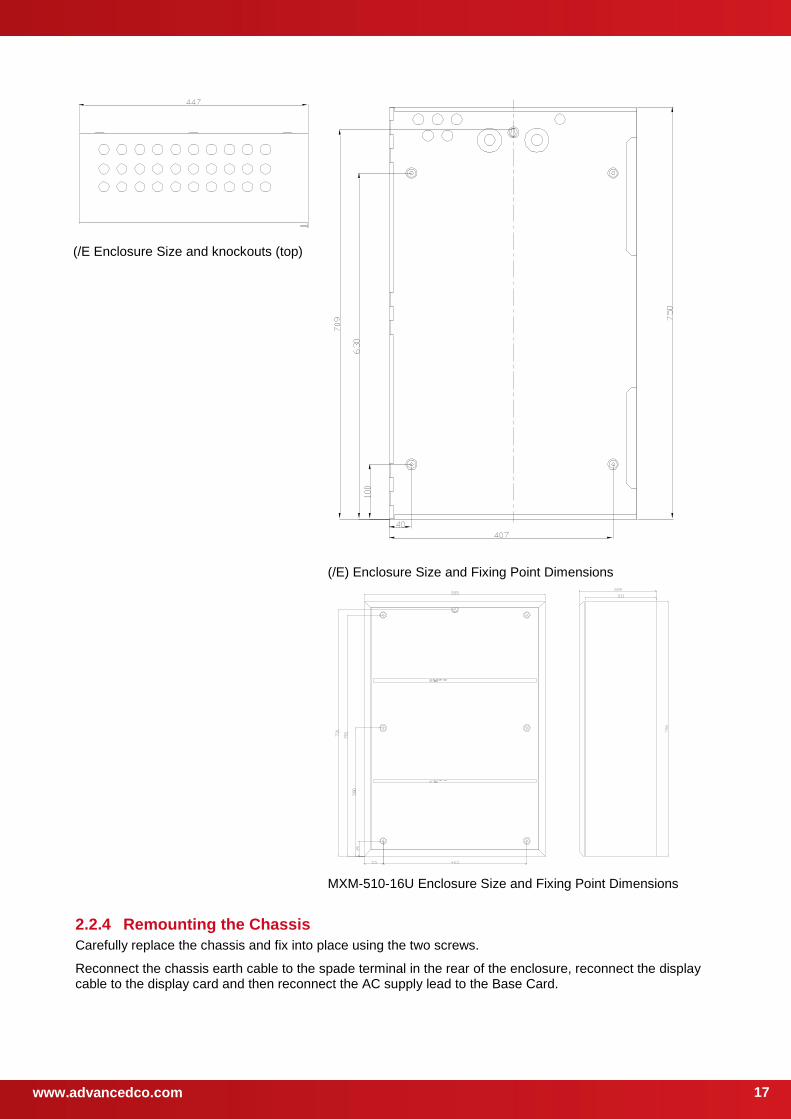
(/E Enclosure Size and knockouts (top)
(/E) Enclosure Size and Fixing Point Dimensions
MXM-510-16U Enclosure Size and Fixing Point Dimensions
2.2.4 Remounting the Chassis
Carefully replace the chassis and fix into place using the two screws.
Reconnect the chassis earth cable to the spade terminal in the rear of the enclosure, reconnect the display cable to the display card and then reconnect the AC supply lead to the Base Card.
www.advancedco.com 18
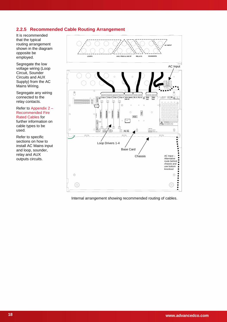
2.2.5 Recommended Cable Routing Arrangement
It is recommended that the typical routing arrangement shown in the diagram opposite be employed.
Segregate the low voltage wiring (Loop Circuit, Sounder Circuits and AUX Supply) from the AC Mains Wiring.
Segregate any wiring connected to the relay contacts.
Refer to Appendix 2 – Recommended Fire Rated Cables for further information on cable types to be used.
Refer to specific sections on how to install AC Mains input and loop, sounder, relay and AUX outputs circuits.
WARNING: HIGH VOLTAGE INSID
DO NOT REMOVE COVER
No Serviceable Parts Inside
Loop Drivers 1-4
Base Card
Chassis
AC Input
Loop 1 Loop 2 Loop 3 Loop 4 SND 3&4
SND 1&2
AUX PBUS SW I/P
RLY1 RLY2
LOOPS AUX, PBUS & SW I/P RELAYS SOUNDERS
AC INPUT
AC Input – Alternative route behind chassis and use bottom
knockout
Internal arrangement showing recommended routing of cables.
www.advancedco.com
19
2.3 Loop Driver Installation The 5100, 5100V and 5100N panels are factory fitted with one loop driver.
The 5200, 5200V and 5200N panels can be fitted with up to two loop drivers – factory fitted with at least one loop driver.
The 5400, 5400V and 5400N panels can be fitted with up to four loop drivers – factory fitted with at least one loop driver.
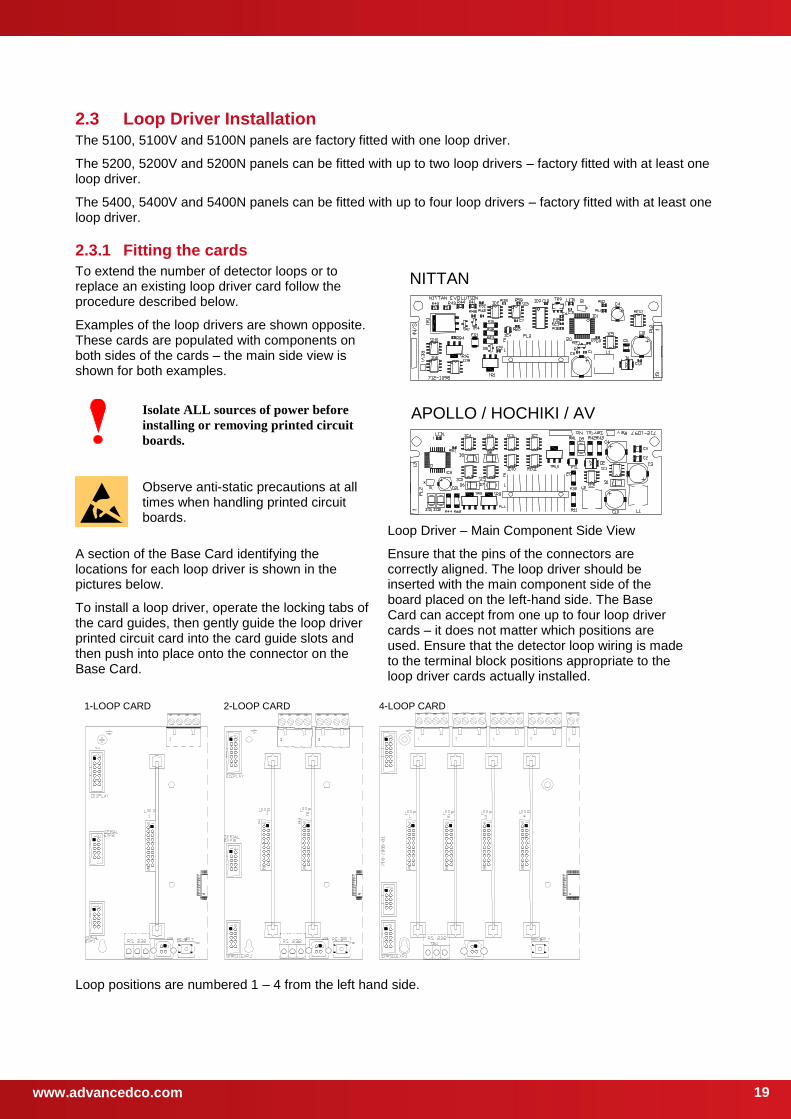
2.3.1 Fitting the cards
To extend the number of detector loops or to replace an existing loop driver card follow the procedure described below.
Examples of the loop drivers are shown opposite. These cards are populated with components on both sides of the cards – the main side view is shown for both examples.
NITTAN
APOLLO / HOCHIKI / AV
Loop Driver – Main Component Side View
Isolate ALL sources of power before
installing or removing printed circuit
boards.
Observe anti-static precautions at all times when handling printed circuit boards.
A section of the Base Card identifying the locations for each loop driver is shown in the pictures below.
To install a loop driver, operate the locking tabs of the card guides, then gently guide the loop driver printed circuit card into the card guide slots and then push into place onto the connector on the Base Card.
Ensure that the pins of the connectors are correctly aligned. The loop driver should be inserted with the main component side of the board placed on the left-hand side. The Base Card can accept from one up to four loop driver cards – it does not matter which positions are used. Ensure that the detector loop wiring is made to the terminal block positions appropriate to the loop driver cards actually installed.
1-LOOP CARD 2-LOOP CARD 4-LOOP CARD
Loop positions are numbered 1 – 4 from the left hand side.
www.advancedco.com 20
2.3.2 Removing a Loop Driver Card
To remove a loop driver, remove all power and follow the procedure above but:
Take a firm hold of top of the loop driver card. Gradually and carefully pull the loop driver vertically away from the base card and guide it out of the slots in the card guides.
2.4 Plug-In / Peripheral Bus Modules
All panels provide provision for installation / use of local peripheral cards to provide additional functions. The peripherals are connected via an isolated bus interface.
Each panel supports either a plug-in 2-Way Relay card or a plug-in General Routing Interface card (peripheral bus module).
All panels also support the connection of up to sixteen Mxp-034 4-Way Programmable Sounder Modules 5, up
to sixteen Mxp-035 4-Way Programmable Relay Modules and other peripheral bus modules housed in separate enclosures. All panels except the small enclosure (/S) support the mounting of one peripheral module on the chassis plate.
Refer to the wiring installation section (2.5.8) for details of how to connect the peripheral modules and section (2.5.5) for details of the network connections.
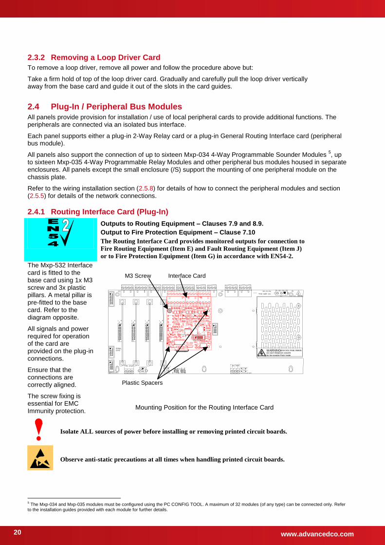
2.4.1 Routing Interface Card (Plug-In)
Outputs to Routing Equipment – Clauses 7.9 and 8.9.
Output to Fire Protection Equipment – Clause 7.10
The Routing Interface Card provides monitored outputs for connection to
Fire Routing Equipment (Item E) and Fault Routing Equipment (Item J)
or to Fire Protection Equipment (Item G) in accordance with EN54-2.
The Mxp-532 Interface card is fitted to the base card using 1x M3 screw and 3x plastic pillars. A metal pillar is pre-fitted to the base card. Refer to the diagram opposite.
All signals and power required for operation of the card are provided on the plug-in connections.
Ensure that the connections are correctly aligned.
The screw fixing is essential for EMC Immunity protection.
WARNING: HIGH VOLTAGE INSIDE DO NOT REMOVE COVER No Serviceable Parts Inside
Plastic Spacers
M3 Screw Interface Card
Mounting Position for the Routing Interface Card
Isolate ALL sources of power before installing or removing printed circuit boards.
Observe anti-static precautions at all times when handling printed circuit boards.
5 The Mxp-034 and Mxp-035 modules must be configured using the PC CONFIG TOOL. A maximum of 32 modules (of any type) can be connected only. Refer
to the installation guides provided with each module for further details.
www.advancedco.com
21
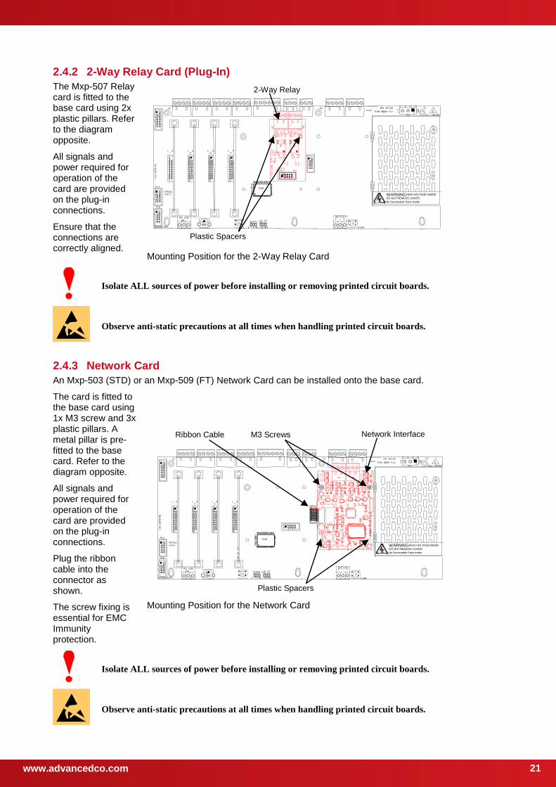
2.4.2 2-Way Relay Card (Plug-In)
The Mxp-507 Relay card is fitted to the base card using 2x plastic pillars. Refer to the diagram opposite.
All signals and power required for operation of the card are provided on the plug-in connections.
Ensure that the connections are correctly aligned.
WARNING: HIGH VOLTAGE INSIDE
DO NOT REMOVE COVER
No Serviceable Parts Inside
Plastic Spacers
2-Way Relay
Mounting Position for the 2-Way Relay Card
Isolate ALL sources of power before installing or removing printed circuit boards.
Observe anti-static precautions at all times when handling printed circuit boards.
2.4.3 Network Card
An Mxp-503 (STD) or an Mxp-509 (FT) Network Card can be installed onto the base card.
The card is fitted to the base card using 1x M3 screw and 3x plastic pillars. A metal pillar is pre-fitted to the base card. Refer to the diagram opposite.
All signals and power required for operation of the card are provided on the plug-in connections.
Plug the ribbon cable into the connector as shown.
The screw fixing is essential for EMC Immunity protection.
WARNING: HIGH VOLTAGE INSIDE DO NOT REMOVE COVER No Serviceable Parts Inside
Plastic Spacers
Network Interface M3 Screws Ribbon Cable
Mounting Position for the Network Card
Isolate ALL sources of power before installing or removing printed circuit boards.
Observe anti-static precautions at all times when handling printed circuit boards.
www.advancedco.com 22
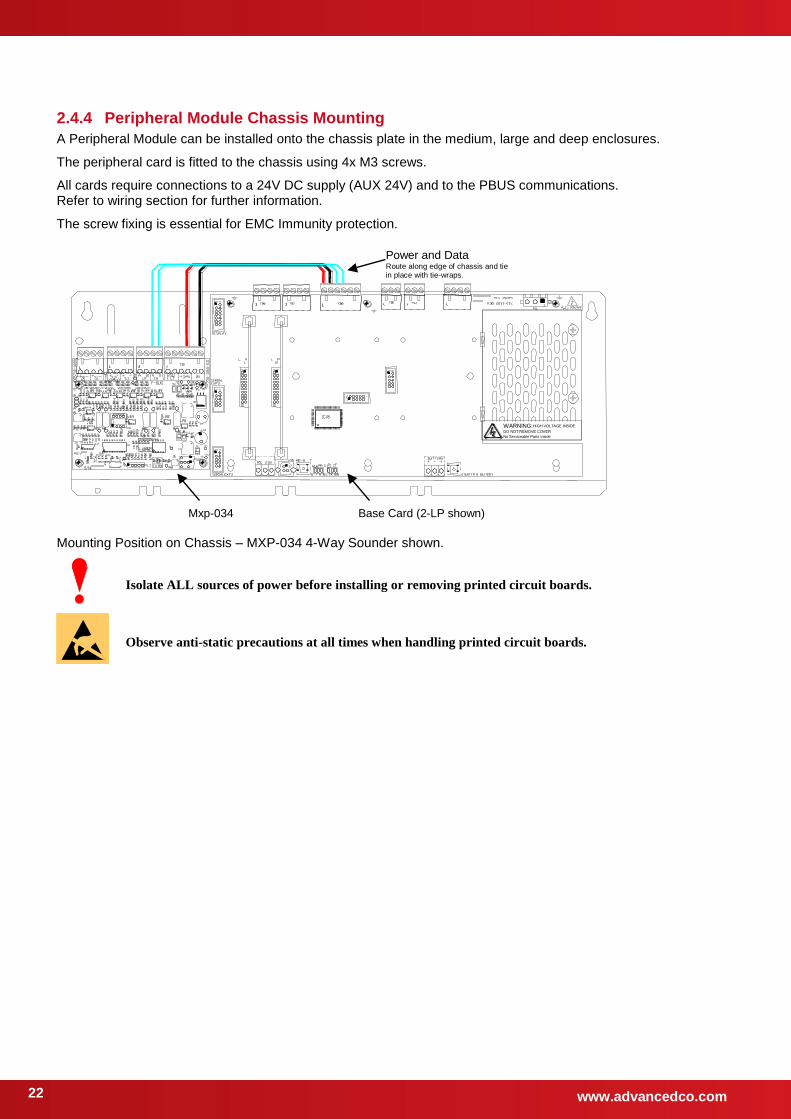
2.4.4 Peripheral Module Chassis Mounting
A Peripheral Module can be installed onto the chassis plate in the medium, large and deep enclosures.
The peripheral card is fitted to the chassis using 4x M3 screws.
All cards require connections to a 24V DC supply (AUX 24V) and to the PBUS communications. Refer to wiring section for further information.
The screw fixing is essential for EMC Immunity protection.
WARNING: HIGH VOLTAGE INSIDE DO NOT REMOVE COVER No Serviceable Parts Inside
Mxp-034
Power and Data Route along edge of chassis and tie in place with tie-wraps.
Base Card (2-LP shown)
Mounting Position on Chassis – MXP-034 4-Way Sounder shown.
Isolate ALL sources of power before installing or removing printed circuit boards.
Observe anti-static precautions at all times when handling printed circuit boards.

www.advancedco.com
23
2.4.5 VdS Interface Module Chassis Mounting
An Mxp-504 VdS Interface Module can be installed onto the chassis plate in the medium, large and deep enclosures.
Outputs to Routing Equipment – Clauses 7.9 and 8.9.
The Routing Interface Card provides monitored outputs for connection to
Fire Routing Equipment (Item E) in accordance with EN54-2.
This card also provides a serial interface and power to FAT and FBF devices and an interface to an FSD key deposit box adaptor.
The circuit card is fitted to the chassis using 4x M3 screws.
The screw fixing is essential for EMC Immunity protection.
All signals and power required for operation of the card are provided on the ribbon cable connections.
WARNING: HIGH VOLTAGE INSIDE DO NOT REMOVE COVER No Serviceable Parts Inside
VdS I/F Base Card (2-LP shown) Ribbon Cable
Mounting Position on Chassis.
Isolate ALL sources of power before installing or removing printed circuit boards.
2.4.5.1 Option Relay Card
An optional Mxp-508 (8-Way Relay Card) can be mounted on top of the interface card to provide
additional relay output circuits. Use the supplied pillars to secure the Interface card to the chassis
using the lower 4 mounting holes. Mount the relay card onto the pillars using the supplied M3
screws and connect the ribbon cable between PL1 on the relay card and PL3 on the interface
card.
2.4.5.2 Optional Redundant Ring Controller
An IFAM ADP-N3E Redundant Controller (Master) or ADP-N3S (Slave) can be installed alongside the VdS Interface card to provide a redundant ring transmission path to FAT and FBF devices.
In the /D enclosure, this circuit card can be fitted to the enclosure sidewall using 4x M3 screws.
For other enclosure sizes, the card must be mounted in a separate enclosure that is connected to the panel via rigid conduit and must be located ≤ 3 metres from the panel.
See Section 2.5.13.2 for wiring connection information.
www.advancedco.com 24
2.5 Wiring Installation All electrical wiring installation work should be carried out in accordance with the code of practice or applicable national standards appropriate to the country of installation.
To maintain electrical integrity of the SELV wiring on the input, output, loop and communications lines all SELV wiring should be segregated from the LV mains wiring and be wired using cable with insulation suitable for the application.
To minimise the effects of EMC interference all data wiring circuits should be wired with a twisted pair of conductors with a cross sectional area suitable for the loading conditions.
In areas where cabling may come into contact with high frequency interference, such as portable radio transceivers etc. the data wiring cable should be of a twisted pair construction within an overall screen. Care should be taken to correctly terminate this screen, refer to the appropriate sections of this manual for further information for each circuit type.
NB: Minimum / Maximum cable size for all external connections is limited to 0.5mm² / 2.5mm² (22-14AWG).
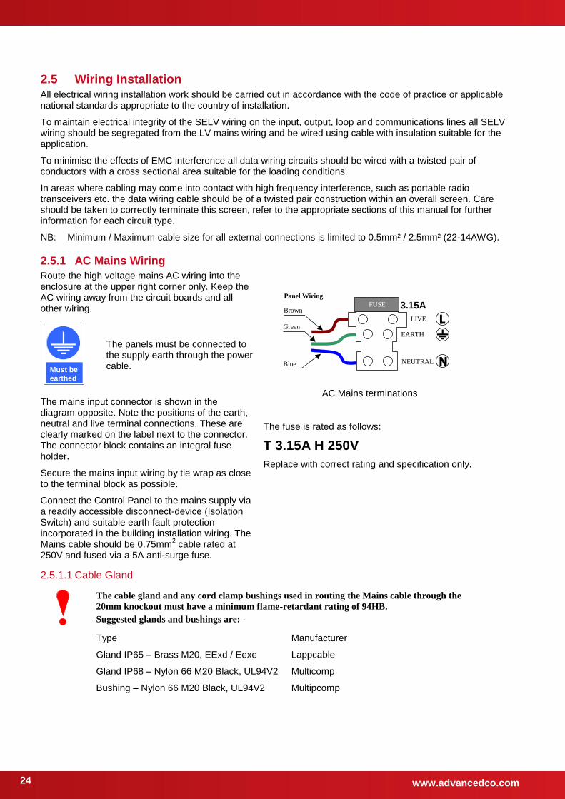
2.5.1 AC Mains Wiring
Route the high voltage mains AC wiring into the enclosure at the upper right corner only. Keep the AC wiring away from the circuit boards and all other wiring.
FUSE Brown
Green LIVE
EARTH
NEUTRAL
Panel Wiring
Blue
3.15A
AC Mains terminations
The fuse is rated as follows:
T 3.15A H 250V
Replace with correct rating and specification only.
Must be
earthed
The panels must be connected to the supply earth through the power cable.
The mains input connector is shown in the diagram opposite. Note the positions of the earth, neutral and live terminal connections. These are clearly marked on the label next to the connector. The connector block contains an integral fuse holder.
Secure the mains input wiring by tie wrap as close to the terminal block as possible.
Connect the Control Panel to the mains supply via a readily accessible disconnect-device (Isolation Switch) and suitable earth fault protection incorporated in the building installation wiring. The Mains cable should be 0.75mm
2 cable rated at
250V and fused via a 5A anti-surge fuse.
2.5.1.1 Cable Gland
The cable gland and any cord clamp bushings used in routing the Mains cable through the
20mm knockout must have a minimum flame-retardant rating of 94HB.
Suggested glands and bushings are: -
Type
Gland IP65 – Brass M20, EExd / Eexe
Gland IP68 – Nylon 66 M20 Black, UL94V2
Bushing – Nylon 66 M20 Black, UL94V2
Manufacturer
Lappcable
Multicomp
Multipcomp
www.advancedco.com
25
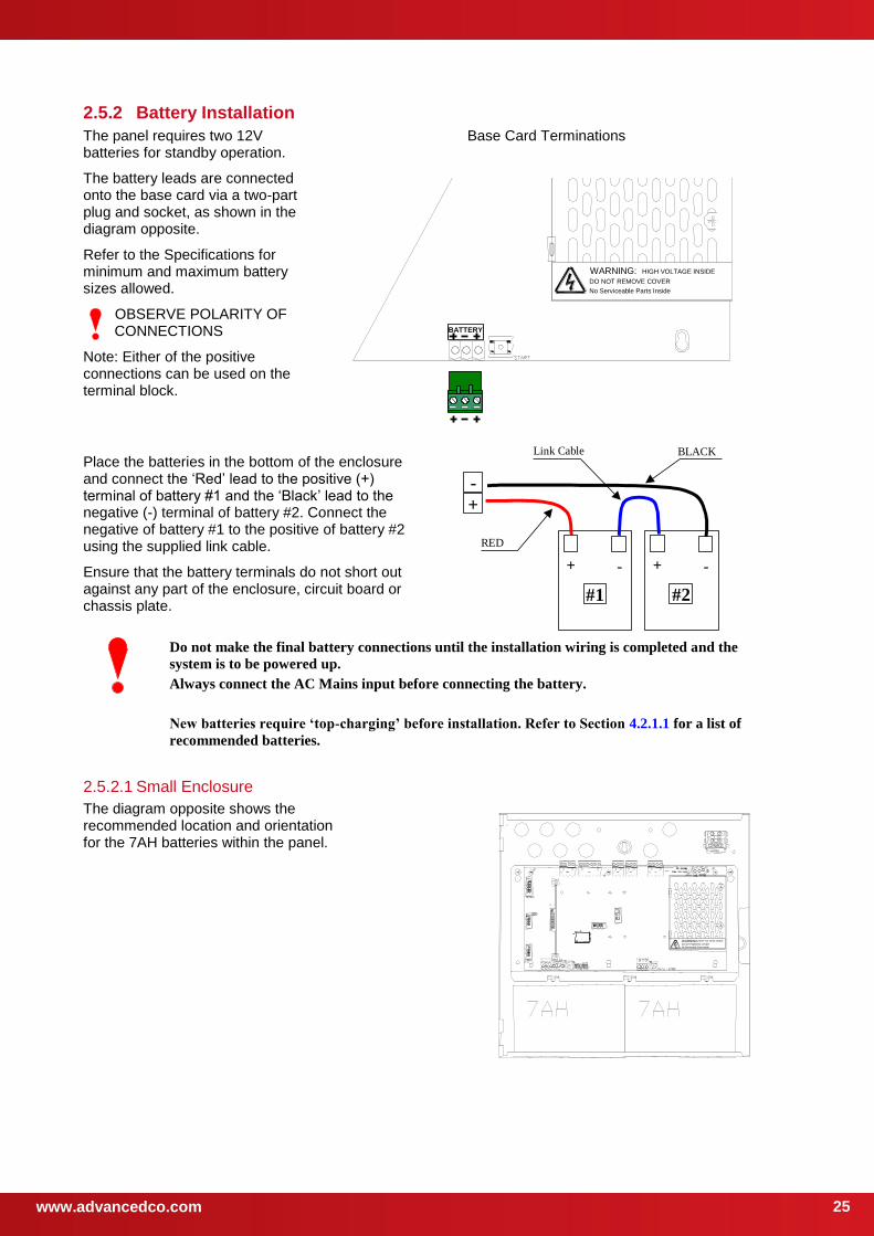
2.5.2 Battery Installation
The panel requires two 12V batteries for standby operation.
The battery leads are connected onto the base card via a two-part plug and socket, as shown in the diagram opposite.
Refer to the Specifications for minimum and maximum battery sizes allowed.
OBSERVE POLARITY OF CONNECTIONS
Note: Either of the positive connections can be used on the terminal block.
Base Card Terminations
WARNING: HIGH VOLTAGE INSIDE
DO NOT REMOVE COVER
No Serviceable Parts Inside
BATTERY
Place the batteries in the bottom of the enclosure and connect the ‘Red’ lead to the positive (+) terminal of battery #1 and the ‘Black’ lead to the negative (-) terminal of battery #2. Connect the negative of battery #1 to the positive of battery #2 using the supplied link cable.
Ensure that the battery terminals do not short out against any part of the enclosure, circuit board or chassis plate.
+ - + -
+
-
#1 #2
RED
BLACKLink Cable
Do not make the final battery connections until the installation wiring is completed and the
system is to be powered up.
Always connect the AC Mains input before connecting the battery.
New batteries require ‘top-charging’ before installation. Refer to Section 4.2.1.1 for a list of
recommended batteries.
2.5.2.1 Small Enclosure
The diagram opposite shows the recommended location and orientation for the 7AH batteries within the panel.
WARNING: HIGH VOLTAGE INSIDE
DO NOT REMOVE COVER
No Serviceable Parts Inside
www.advancedco.com 26
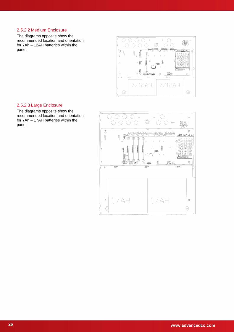
2.5.2.2 Medium Enclosure
The diagrams opposite show the recommended location and orientation for 7Ah – 12AH batteries within the panel.
WARNING: HIGH VOLTAGE INSIDE
DO NOT REMOVE COVER
No Serviceable Parts Inside
2.5.2.3 Large Enclosure
The diagrams opposite show the recommended location and orientation for 7Ah – 17AH batteries within the panel.
WARNING: HIGH VOLTAGE INSID
DO NOT REMOVE COVER
No Serviceable Parts Inside
www.advancedco.com
27
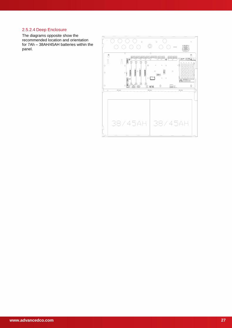
2.5.2.4 Deep Enclosure
The diagrams opposite show the recommended location and orientation for 7Ah – 38AH/45AH batteries within the panel.
WARNING: HIGH VOLTAGE INSID
DO NOT REMOVE COVER
No Serviceable Parts Inside
www.advancedco.com 28
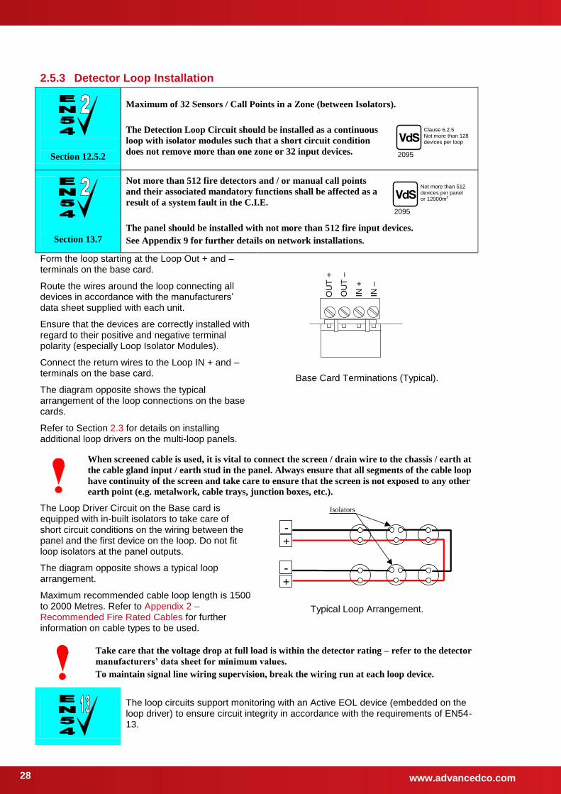
2.5.3 Detector Loop Installation
Section 12.5.2
Maximum of 32 Sensors / Call Points in a Zone (between Isolators).
The Detection Loop Circuit should be installed as a continuous
loop with isolator modules such that a short circuit condition
does not remove more than one zone or 32 input devices.
Section 13.7
Not more than 512 fire detectors and / or manual call points
and their associated mandatory functions shall be affected as a
result of a system fault in the C.I.E.
The panel should be installed with not more than 512 fire input devices.
See Appendix 9 for further details on network installations.
Form the loop starting at the Loop Out + and – terminals on the base card.
Route the wires around the loop connecting all devices in accordance with the manufacturers’ data sheet supplied with each unit.
Ensure that the devices are correctly installed with regard to their positive and negative terminal polarity (especially Loop Isolator Modules).
Connect the return wires to the Loop IN + and – terminals on the base card.
The diagram opposite shows the typical arrangement of the loop connections on the base cards.
Refer to Section 2.3 for details on installing additional loop drivers on the multi-loop panels.
IN –
IN +
OU
T –
OU
T +
Base Card Terminations (Typical).
When screened cable is used, it is vital to connect the screen / drain wire to the chassis / earth at
the cable gland input / earth stud in the panel. Always ensure that all segments of the cable loop
have continuity of the screen and take care to ensure that the screen is not exposed to any other
earth point (e.g. metalwork, cable trays, junction boxes, etc.).
The Loop Driver Circuit on the Base card is equipped with in-built isolators to take care of short circuit conditions on the wiring between the panel and the first device on the loop. Do not fit loop isolators at the panel outputs.
The diagram opposite shows a typical loop arrangement.
Maximum recommended cable loop length is 1500 to 2000 Metres. Refer to Appendix 2 – Recommended Fire Rated Cables for further information on cable types to be used.
+
-
+
-
Isolators
Typical Loop Arrangement.
Take care that the voltage drop at full load is within the detector rating – refer to the detector
manufacturers’ data sheet for minimum values.
To maintain signal line wiring supervision, break the wiring run at each loop device.
The loop circuits support monitoring with an Active EOL device (embedded on the loop driver) to ensure circuit integrity in accordance with the requirements of EN54-13.
V d S
2095
Clause 6.2.5 Not more than 128 devices per loop
V d S
2095
Not more than 512 devices per panel or 12000m2
www.advancedco.com
29
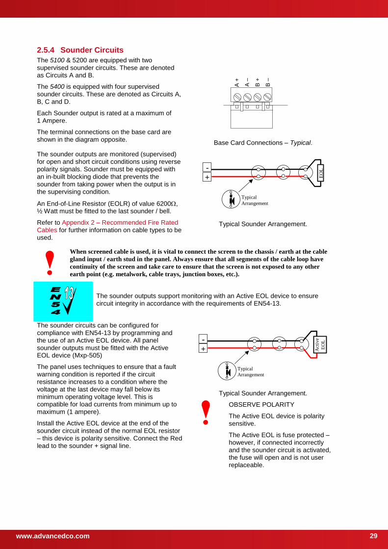
2.5.4 Sounder Circuits
The 5100 & 5200 are equipped with two supervised sounder circuits. These are denoted as Circuits A and B.
The 5400 is equipped with four supervised sounder circuits. These are denoted as Circuits A, B, C and D.
Each Sounder output is rated at a maximum of 1 Ampere.
The terminal connections on the base card are shown in the diagram opposite.
B –
B +
A –
A +
Base Card Connections – Typical.
The sounder outputs are monitored (supervised) for open and short circuit conditions using reverse polarity signals. Sounder must be equipped with an in-built blocking diode that prevents the sounder from taking power when the output is in the supervising condition.
An End-of-Line Resistor (EOLR) of value 6200, ½ Watt must be fitted to the last sounder / bell.
Refer to Appendix 2 – Recommended Fire Rated Cables for further information on cable types to be used.
+
-
Typical
Arrangement
EO
L
Typical Sounder Arrangement.
When screened cable is used, it is vital to connect the screen to the chassis / earth at the cable
gland input / earth stud in the panel. Always ensure that all segments of the cable loop have
continuity of the screen and take care to ensure that the screen is not exposed to any other
earth point (e.g. metalwork, cable trays, junction boxes, etc.).
The sounder outputs support monitoring with an Active EOL device to ensure circuit integrity in accordance with the requirements of EN54-13.
The sounder circuits can be configured for compliance with EN54-13 by programming and the use of an Active EOL device. All panel sounder outputs must be fitted with the Active EOL device (Mxp-505)
The panel uses techniques to ensure that a fault warning condition is reported if the circuit resistance increases to a condition where the voltage at the last device may fall below its minimum operating voltage level. This is compatible for load currents from minimum up to maximum (1 ampere).
Install the Active EOL device at the end of the sounder circuit instead of the normal EOL resistor – this device is polarity sensitive. Connect the Red lead to the sounder + signal line.
+
-
Typical
Arrangement
Act
ive
EO
L
Typical Sounder Arrangement.
OBSERVE POLARITY
The Active EOL device is polarity sensitive.
The Active EOL is fuse protected – however, if connected incorrectly and the sounder circuit is activated, the fuse will open and is not user replaceable.
www.advancedco.com 30
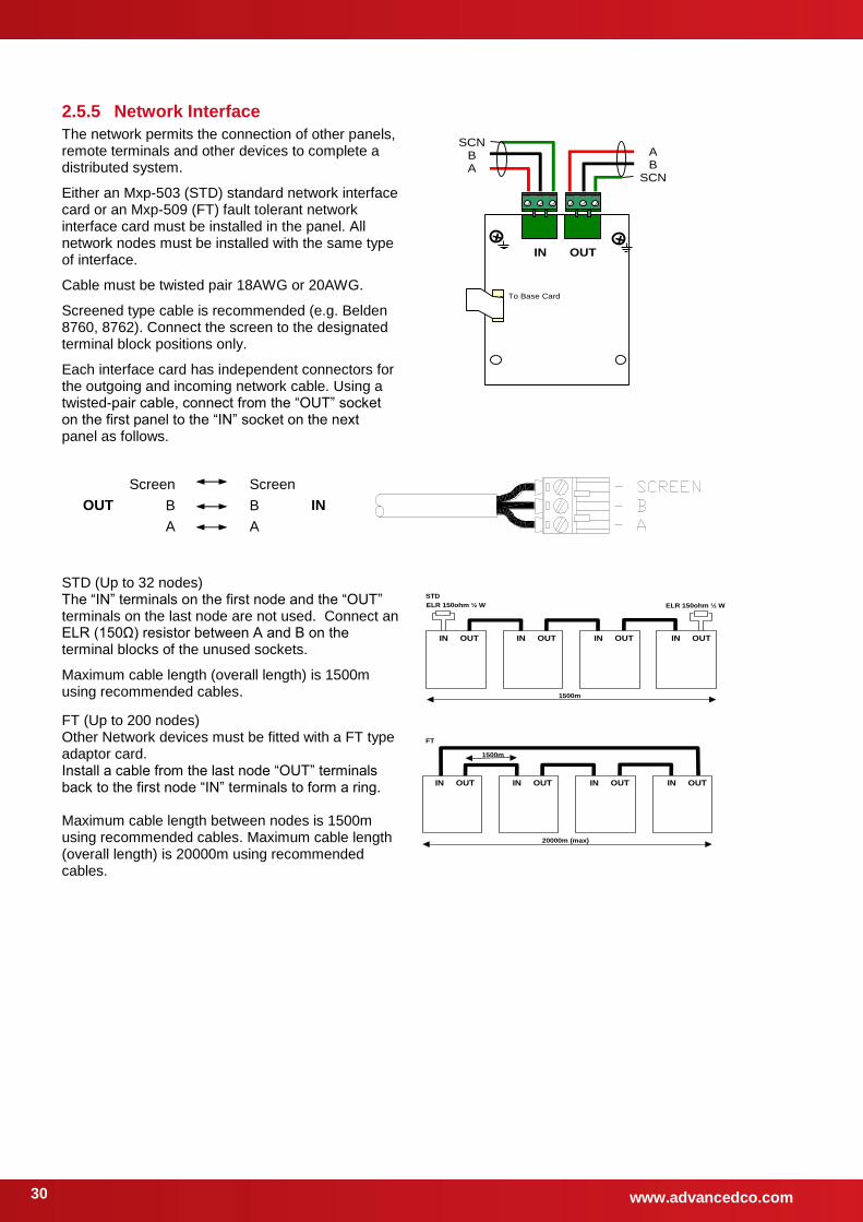
2.5.5 Network Interface
The network permits the connection of other panels, remote terminals and other devices to complete a distributed system.
Either an Mxp-503 (STD) standard network interface card or an Mxp-509 (FT) fault tolerant network interface card must be installed in the panel. All network nodes must be installed with the same type of interface.
Cable must be twisted pair 18AWG or 20AWG.
Screened type cable is recommended (e.g. Belden 8760, 8762). Connect the screen to the designated terminal block positions only.
Each interface card has independent connectors for the outgoing and incoming network cable. Using a twisted-pair cable, connect from the “OUT” socket on the first panel to the “IN” socket on the next panel as follows.
SCN B A
A B
SCN
IN OUT
To Base Card
OUT
Screen
B
A
Screen
B
A
IN
STD (Up to 32 nodes) The “IN” terminals on the first node and the “OUT” terminals on the last node are not used. Connect an ELR (150Ω) resistor between A and B on the terminal blocks of the unused sockets.
Maximum cable length (overall length) is 1500m using recommended cables.
FT (Up to 200 nodes) Other Network devices must be fitted with a FT type adaptor card. Install a cable from the last node “OUT” terminals back to the first node “IN” terminals to form a ring. Maximum cable length between nodes is 1500m using recommended cables. Maximum cable length (overall length) is 20000m using recommended cables.
OUT IN OUT IN OUT IN OUT IN
ELR 150ohm ½ W ELR 150ohm ½ W
1500m
STD
OUT IN OUT IN OUT IN OUT IN
20000m (max)
1500m
FT
www.advancedco.com
31
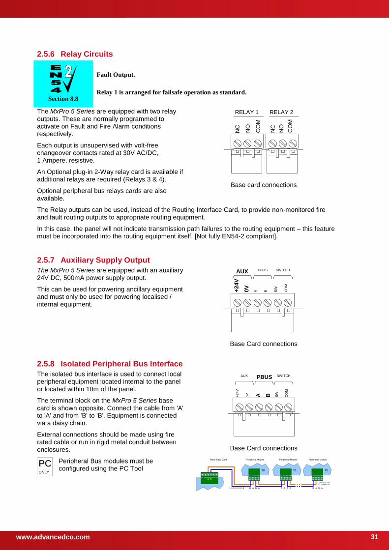
2.5.6 Relay Circuits
Section 8.8
Fault Output.
Relay 1 is arranged for failsafe operation as standard.
The MxPro 5 Series are equipped with two relay outputs. These are normally programmed to activate on Fault and Fire Alarm conditions respectively.
Each output is unsupervised with volt-free changeover contacts rated at 30V AC/DC, 1 Ampere, resistive.
An Optional plug-in 2-Way relay card is available if additional relays are required (Relays 3 & 4).
Optional peripheral bus relays cards are also available.
NC
CO
M
NO
NC
NO
CO
M
RELAY 1 RELAY 2
Base card connections
The Relay outputs can be used, instead of the Routing Interface Card, to provide non-monitored fire and fault routing outputs to appropriate routing equipment.
In this case, the panel will not indicate transmission path failures to the routing equipment – this feature must be incorporated into the routing equipment itself. [Not fully EN54-2 compliant].
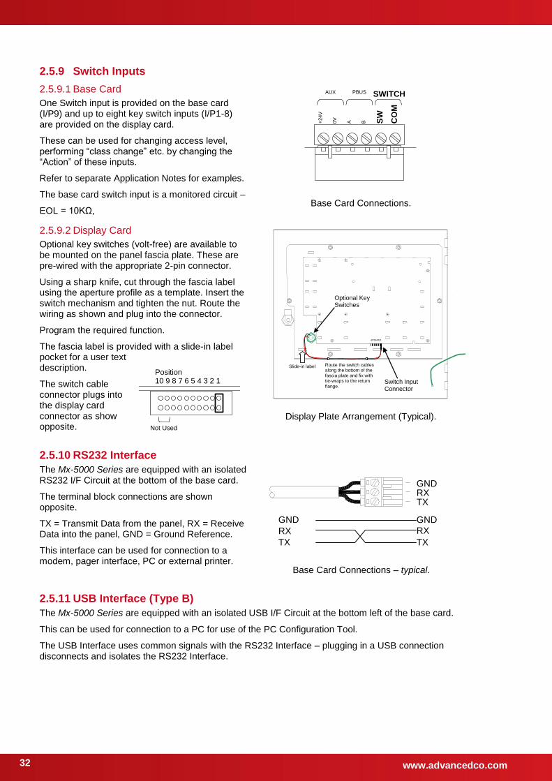
2.5.7 Auxiliary Supply Output
The MxPro 5 Series are equipped with an auxiliary 24V DC, 500mA power supply output.
This can be used for powering ancillary equipment and must only be used for powering localised / internal equipment.
B
A 0V
+2
4V
SW
CO
M
AUX SWITCH PBUS
Base Card connections
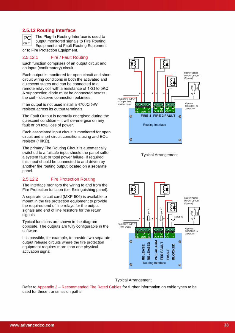
2.5.8 Isolated Peripheral Bus Interface
The isolated bus interface is used to connect local peripheral equipment located internal to the panel or located within 10m of the panel.
The terminal block on the MxPro 5 Series base card is shown opposite. Connect the cable from 'A' to 'A' and from 'B' to 'B'. Equipment is connected via a daisy chain.
External connections should be made using fire rated cable or run in rigid metal conduit between enclosures.
B
A
0V
+24V
SW
CO
M
AUX SWITCH PBUS
Base Card connections
Peripheral Bus modules must be configured using the PC Tool
Panel Base Card
TB
B A B A
TB
B A B A
TB
B A B A To External Modules
Last Module – FIT EOL Jumper to IN
Peripheral Module Peripheral Module Peripheral Module
A B
PPCC OONNLLYY
www.advancedco.com 32
Position 10 9 8 7 6 5 4 3 2 1
Not Used
2.5.9 Switch Inputs
2.5.9.1 Base Card
One Switch input is provided on the base card (I/P9) and up to eight key switch inputs (I/P1-8) are provided on the display card.
These can be used for changing access level, performing “class change” etc. by changing the “Action” of these inputs.
Refer to separate Application Notes for examples.
The base card switch input is a monitored circuit –
EOL = 10KΩ,
B
A
0V
+24V
SW
CO
M
AUX SWITCH PBUS
Base Card Connections.
2.5.9.2 Display Card
Optional key switches (volt-free) are available to be mounted on the panel fascia plate. These are pre-wired with the appropriate 2-pin connector.
Using a sharp knife, cut through the fascia label using the aperture profile as a template. Insert the switch mechanism and tighten the nut. Route the wiring as shown and plug into the connector.
Program the required function.
The fascia label is provided with a slide-in label pocket for a user text description.
The switch cable connector plugs into the display card connector as show opposite.
Switch Input Connector
Optional Key Switches
--87654321
Route the switch cables along the bottom of the fascia plate and fix with tie-wraps to the return
flange.
Slide-in label
Display Plate Arrangement (Typical).
2.5.10 RS232 Interface
The Mx-5000 Series are equipped with an isolated RS232 I/F Circuit at the bottom of the base card.
The terminal block connections are shown opposite.
TX = Transmit Data from the panel, RX = Receive Data into the panel, GND = Ground Reference.
This interface can be used for connection to a modem, pager interface, PC or external printer.
Base Card Connections – typical.
2.5.11 USB Interface (Type B)
The Mx-5000 Series are equipped with an isolated USB I/F Circuit at the bottom left of the base card.
This can be used for connection to a PC for use of the PC Configuration Tool.
The USB Interface uses common signals with the RS232 Interface – plugging in a USB connection disconnects and isolates the RS232 Interface.
GND RX TX
GND
RX
TX
GND
RX
TX
www.advancedco.com
33
2.5.12 Routing Interface
The Plug-In Routing Interface is used to output monitored signals to Fire Routing Equipment and Fault Routing Equipment
or to Fire Protection Equipment.
2.5.12.1 Fire / Fault Routing
Each function comprises of an output circuit and an input (confirmatory) circuit.
Each output is monitored for open circuit and short circuit wiring conditions in both the activated and quiescent states and can be connected to a remote relay coil with a resistance of 1KΩ to 5KΩ. A suppression diode must be connected across the coil – observe connection polarities.
If an output is not used install a 4700Ω ½W resistor across its output terminals.
The Fault Output is normally energised during the quiescent condition – it will de-energise on any fault or on total loss of power.
Each associated input circuit is monitored for open circuit and short circuit conditions using and EOL resistor (10KΩ).
The primary Fire Routing Circuit is automatically switched to a failsafe input should the panel suffer a system fault or total power failure. If required, this input should be connected to and driven by another fire routing output located on a separate panel.
Routing Interface
FIRE 1 FAULT
+ - + -
FAILSAFE INPUT – Output from
another panel
OUT IN OUT IN FSI OUT IN
FIRE 2
+ -
47
0R
10
K
MONITORED INPUT CIRCUIT (Typical)
Options: 3K3/680R or 10K/470R
Typical Arrangement
2.5.12.2 Fire Protection Routing
The Interface monitors the wiring to and from the Fire Protection function (i.e. Extinguishing panel).
A separate circuit card (MXP-506) is available to mount in the fire protection equipment to provide the required end of line relays for the output signals and end of line resistors for the return signals.
Typical functions are shown in the diagram opposite. The outputs are fully configurable in the software.
It is possible, for example, to provide two separate output release circuits where the fire protection equipment requires more than one physical activation signal.
Routing Interface
RE
LE
AS
E
+ - + -
FAILSAFE INPUT – NOT USED
OUT IN OUT IN FSI OUT IN
+ -
47
0R
10
K
MONITORED INPUT CIRCUIT (Typical)
RE
LE
AS
ED
PR
E-A
LA
RM
FE
S F
AU
LT
FA
UL
T
BL
OC
KE
D
Options: 3K3/680R or 10K/470R
Inp
ut
#1
Inp
ut
#2
Input #3
Typical Arrangement
Refer to Appendix 2 – Recommended Fire Rated Cables for further information on cable types to be used for these transmission paths.
PPCC OONNLLYY
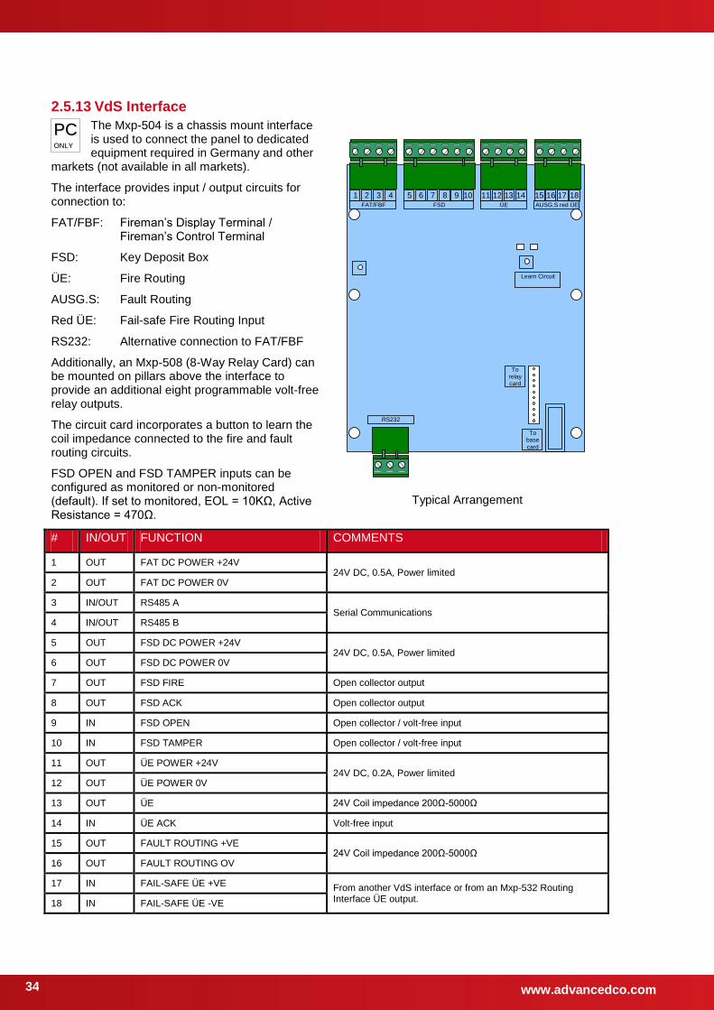
www.advancedco.com 34
2.5.13 VdS Interface
The Mxp-504 is a chassis mount interface is used to connect the panel to dedicated equipment required in Germany and other
markets (not available in all markets).
The interface provides input / output circuits for connection to:
FAT/FBF: Fireman’s Display Terminal / Fireman’s Control Terminal
FSD: Key Deposit Box
ÜE: Fire Routing
AUSG.S: Fault Routing
Red ÜE: Fail-safe Fire Routing Input
RS232: Alternative connection to FAT/FBF
Additionally, an Mxp-508 (8-Way Relay Card) can be mounted on pillars above the interface to provide an additional eight programmable volt-free relay outputs.
The circuit card incorporates a button to learn the coil impedance connected to the fire and fault routing circuits.
FSD OPEN and FSD TAMPER inputs can be configured as monitored or non-monitored (default). If set to monitored, EOL = 10KΩ, Active Resistance = 470Ω.
1 2 3 4 15 16 17 18 11 12 13 14 5 6 7 8 9 10 FAT/FBF FSD ÜE AUSG.S red ÜE
RS232
To base
card
To relay card
Learn Circuit
Typical Arrangement
# IN/OUT FUNCTION COMMENTS
1 OUT FAT DC POWER +24V 24V DC, 0.5A, Power limited
2 OUT FAT DC POWER 0V
3 IN/OUT RS485 A Serial Communications
4 IN/OUT RS485 B
5 OUT FSD DC POWER +24V 24V DC, 0.5A, Power limited
6 OUT FSD DC POWER 0V
7 OUT FSD FIRE Open collector output
8 OUT FSD ACK Open collector output
9 IN FSD OPEN Open collector / volt-free input
10 IN FSD TAMPER Open collector / volt-free input
11 OUT ÜE POWER +24V 24V DC, 0.2A, Power limited
12 OUT ÜE POWER 0V
13 OUT ÜE 24V Coil impedance 200Ω-5000Ω
14 IN ÜE ACK Volt-free input
15 OUT FAULT ROUTING +VE 24V Coil impedance 200Ω-5000Ω
16 OUT FAULT ROUTING OV
17 IN FAIL-SAFE ÜE +VE From another VdS interface or from an Mxp-532 Routing Interface ÜE output. 18 IN FAIL-SAFE ÜE -VE
PPCC OONNLLYY
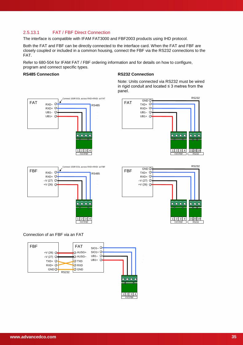
www.advancedco.com
35
2.5.13.1 FAT / FBF Direct Connection
The interface is compatible with IFAM FAT3000 and FBF2003 products using IHD protocol.
Both the FAT and FBF can be directly connected to the interface card. When the FAT and FBF are closely coupled or included in a common housing, connect the FBF via the RS232 connections to the FAT.
Refer to 680-504 for IFAM FAT / FBF ordering information and for details on how to configure, program and connect specific types.
RS485 Connection RS232 Connection
Note: Units connected via RS232 must be wired in rigid conduit and located ≤ 3 metres from the panel.
FAT
1 2 3 4 FAT/FBF
RXD–
RXD+
UB1–
UB1+
RS485
Connect 150R EOL across RXD+/RXD- at FAT
FAT
1 2 3 4 FAT/FBF RS232
21 20 19
TXD+
RXD+
GND
UB1–
UB1+
RS232
FBF
1 2 3 4 FAT/FBF
–V (27)
+V (26)
RS485 RXD–
RXD+
Connect 150R EOL across RXD+/RXD- at FBF
FBF
1 2 3 4 FAT/FBF RS232
21 20 19
TXD+
RXD+
GND
–V (27)
+V (26)
RS232
Connection of an FBF via an FAT
FAT
1 2 3 4 FAT/FBF
FBF
TXD+
RXD+
GND
TXD
RXD
GND RS232
AUSG–
AUSG+
–V (27)
+V (26)
SIO1–
SIO1+
UB1–
UB1+
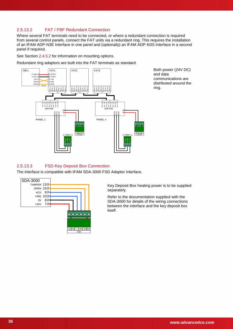
www.advancedco.com 36
2.5.13.2 FAT / FBF Redundant Connection
Where several FAT terminals need to be connected, or where a redundant connection is required from several control panels, connect the FAT units via a redundant ring. This requires the installation of an IFAM ADP-N3E Interface in one panel and (optionally) an IFAM ADP-N3S Interface in a second panel if required.
See Section 2.4.5.2 for information on mounting options.
Redundant ring adaptors are built into the FAT terminals as standard.
FBF1
TXD
RXD
GND RS232
FAT1
TXD
RXD
GND
FAT2 FAT3
1 2 3 4 FAT/FBF RS232
ADP-N3E
0V
TX
RX
TX
RX
0V
1 2 3 4 FAT/FBF RS232
ADP-N3S
0V
TX
RX
TX
RX
0V
PANEL 1 PANEL n
AUSG–
AUSG+
–V (27)
+V (26)
UB
2+
UB
2–
SIO
2+
SIO
2–
UB
1+
UB
1–
SIO
1+
SIO
1–
UB
2+
UB
2–
SIO
2+
SIO
2–
UB
1+
UB
1–
SIO
1+
SIO
1–
UB
2+
UB
2–
SIO
2+
SIO
2–
UB
1+
UB
1–
SIO
1+
SIO
1–
UB
1+
UB
1–
SIO
1+
SIO
1–
UB
2+
UB
2–
SIO
2+
SIO
2–
UB
1+
UB
1–
SIO
1+
SIO
1–
UB
2+
UB
2–
SIO
2+
SIO
2–
Both power (24V DC) and data communications are distributed around the ring.
2.5.13.3 FSD Key Deposit Box Connection
The interface is compatible with IFAM SDA-3000 FSD Adaptor Interface.
SDA-3000
5 6 7 8 9 10 FSD
15
9
10
8
7
13
OPEN
ACK
FIRE
0V
+24V
TAMPER
Key Deposit Box heating power is to be supplied separately.
Refer to the documentation supplied with the SDA-3000 for details of the wiring connections between the interface and the key deposit box itself.
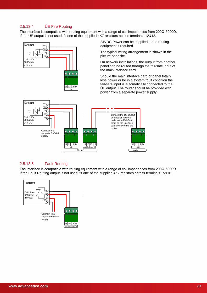
www.advancedco.com
37
2.5.13.4 ÜE Fire Routing
The interface is compatible with routing equipment with a range of coil impedances from 200Ω-5000Ω. If the ÜE output is not used, fit one of the supplied 4K7 resistors across terminals 12&13.
Router
Coil: 200-5000ohm 24V DC
11 12 13 14 ÜE
ACK
FIRE
0V
+24V
24VDC Power can be supplied to the routing equipment if required.
The typical wiring arrangement is shown in the picture opposite.
On network installations, the output from another panel can be routed through the fail-safe input of the main interface card.
Should the main interface card or panel totally lose power or be in a system fault condition the fail-safe input is automatically connected to the ÜE output. The router should be provided with power from a separate power supply.
Router
Coil: 200-5000ohm 24V DC
11 12 13 14 ÜE
ACK
FIRE
0V
+24V
15 16 17 18 AUSG.S red ÜE
11 12 13 14 ÜE
Connect the ÜE Output on another network node to the Fail-Safe Input on the Interface card connected to the router.
Node 1 Node n
0V
Connect to a separate EN54-4 supply
2.5.13.5 Fault Routing
The interface is compatible with routing equipment with a range of coil impedances from 200Ω-5000Ω. If the Fault Routing output is not used, fit one of the supplied 4K7 resistors across terminals 15&16.
Router
15 16 17 18 AUSG.S red ÜE
Coil: 200-5000ohm 24V DC
–
+
+24V
0V
Connect to a separate EN54-4 supply
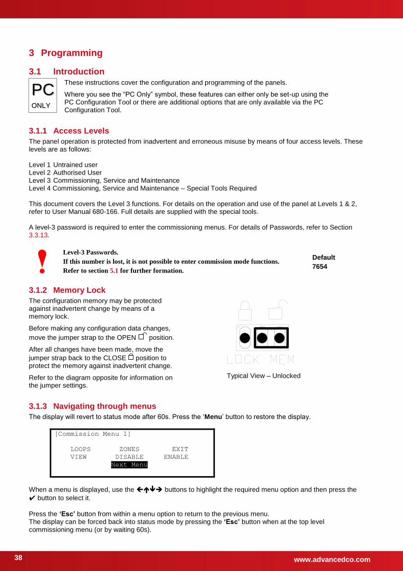
www.advancedco.com 38
3 Programming
3.1 Introduction
PPCC OONNLLYY
These instructions cover the configuration and programming of the panels.
Where you see the “PC Only” symbol, these features can either only be set-up using the PC Configuration Tool or there are additional options that are only available via the PC Configuration Tool.
3.1.1 Access Levels
The panel operation is protected from inadvertent and erroneous misuse by means of four access levels. These levels are as follows: Level 1 Untrained user Level 2 Authorised User Level 3 Commissioning, Service and Maintenance Level 4 Commissioning, Service and Maintenance – Special Tools Required This document covers the Level 3 functions. For details on the operation and use of the panel at Levels 1 & 2, refer to User Manual 680-166. Full details are supplied with the special tools. A level-3 password is required to enter the commissioning menus. For details of Passwords, refer to Section 3.3.13.
Level-3 Passwords.
If this number is lost, it is not possible to enter commission mode functions.
Refer to section 5.1 for further formation.
Default
7654
3.1.2 Memory Lock
The configuration memory may be protected against inadvertent change by means of a memory lock.
Before making any configuration data changes,
move the jumper strap to the OPEN
position.
After all changes have been made, move the
jumper strap back to the CLOSE
position to protect the memory against inadvertent change.
Refer to the diagram opposite for information on the jumper settings.
Typical View – Unlocked
3.1.3 Navigating through menus
The display will revert to status mode after 60s. Press the ‘Menu’ button to restore the display.
[Commission Menu 1]
LOOPS ZONES EXIT
VIEW DISABLE ENABLE
Next Menu
When a menu is displayed, use the buttons to highlight the required menu option and then press the
button to select it.
Press the ‘Esc’ button from within a menu option to return to the previous menu. The display can be forced back into status mode by pressing the ‘Esc’ button when at the top level commissioning menu (or by waiting 60s).
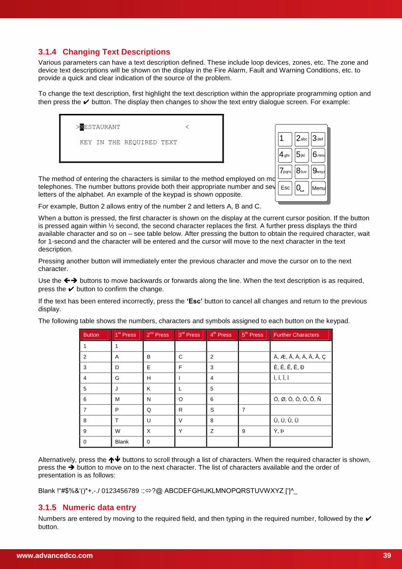
www.advancedco.com
39
3.1.4 Changing Text Descriptions
Various parameters can have a text description defined. These include loop devices, zones, etc. The zone and device text descriptions will be shown on the display in the Fire Alarm, Fault and Warning Conditions, etc. to provide a quick and clear indication of the source of the problem. To change the text description, first highlight the text description within the appropriate programming option and
then press the button. The display then changes to show the text entry dialogue screen. For example:
>RESTAURANT <
KEY IN THE REQUIRED TEXT
The method of entering the characters is similar to the method employed on mobile telephones. The number buttons provide both their appropriate number and several letters of the alphabet. An example of the keypad is shown opposite.
For example, Button 2 allows entry of the number 2 and letters A, B and C.
When a button is pressed, the first character is shown on the display at the current cursor position. If the button is pressed again within ½ second, the second character replaces the first. A further press displays the third available character and so on – see table below. After pressing the button to obtain the required character, wait for 1-second and the character will be entered and the cursor will move to the next character in the text description.
Pressing another button will immediately enter the previous character and move the cursor on to the next character.
Use the buttons to move backwards or forwards along the line. When the text description is as required,
press the button to confirm the change.
If the text has been entered incorrectly, press the ‘Esc’ button to cancel all changes and return to the previous display.
The following table shows the numbers, characters and symbols assigned to each button on the keypad.
Button 1st Press 2
nd Press 3
rd Press 4
th Press 5
th Press Further Characters
1 1
2 A B C 2 Ä, Æ, Å, À, Á, Â, Ã, Ç
3 D E F 3 È, É, Ê, Ë, Đ
4 G H I 4 Ì, Í, Î, Ï
5 J K L 5
6 M N O 6 Ö, Ø, Ò, Ó, Ô, Õ, Ñ
7 P Q R S 7
8 T U V 8 Ù, Ú, Û, Ü
9 W X Y Z 9 Ý, Þ
0 Blank 0
Alternatively, press the buttons to scroll through a list of characters. When the required character is shown, press the button to move on to the next character. The list of characters available and the order of presentation is as follows: Blank !“#$%&‘()*+,-./ 0123456789 :;?@ ABCDEFGHIJKLMNOPQRSTUVWXYZ [‘]^_
3.1.5 Numeric data entry
Numbers are entered by moving to the required field, and then typing in the required number, followed by the
button.
4 ghi 5 jkl 6 mno
2 abc
8 tuv
1 3 def
7 pqrs 9 wxyz
0 Esc Menu
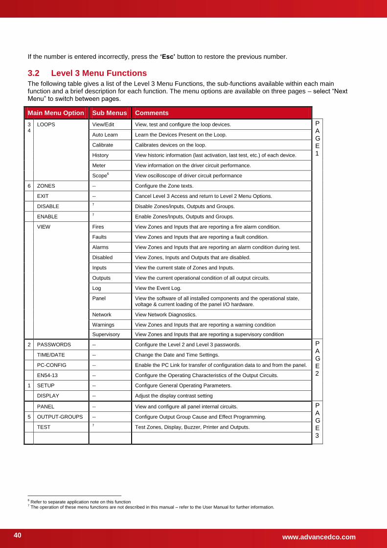
www.advancedco.com 40
If the number is entered incorrectly, press the ‘Esc’ button to restore the previous number.
3.2 Level 3 Menu Functions
The following table gives a list of the Level 3 Menu Functions, the sub-functions available within each main function and a brief description for each function. The menu options are available on three pages – select “Next Menu” to switch between pages.
Main Menu Option Sub Menus Comments
34
LOOPS View/Edit View, test and configure the loop devices. PAGE1
Auto Learn Learn the Devices Present on the Loop.
Calibrate Calibrates devices on the loop.
History View historic information (last activation, last test, etc.) of each device.
Meter View information on the driver circuit performance.
Scope6 View oscilloscope of driver circuit performance
6 ZONES -- Configure the Zone texts.
EXIT -- Cancel Level 3 Access and return to Level 2 Menu Options.
DISABLE 7 Disable Zones/inputs, Outputs and Groups.
ENABLE 7
Enable Zones/Inputs, Outputs and Groups.
VIEW Fires View Zones and Inputs that are reporting a fire alarm condition.
Faults View Zones and Inputs that are reporting a fault condition.
Alarms View Zones and Inputs that are reporting an alarm condition during test.
Disabled View Zones, Inputs and Outputs that are disabled.
Inputs View the current state of Zones and Inputs.
Outputs View the current operational condition of all output circuits.
Log View the Event Log.
Panel View the software of all installed components and the operational state, voltage & current loading of the panel I/O hardware.
Network View Network Diagnostics.
Warnings View Zones and Inputs that are reporting a warning condition
Supervisory View Zones and Inputs that are reporting a supervisory condition
2 PASSWORDS -- Configure the Level 2 and Level 3 passwords. PAGE2
TIME/DATE -- Change the Date and Time Settings.
PC-CONFIG -- Enable the PC Link for transfer of configuration data to and from the panel.
EN54-13 -- Configure the Operating Characteristics of the Output Circuits.
1 SETUP -- Configure General Operating Parameters.
DISPLAY -- Adjust the display contrast setting
PANEL -- View and configure all panel internal circuits. PAGE3
5 OUTPUT-GROUPS -- Configure Output Group Cause and Effect Programming.
TEST 7
Test Zones, Display, Buzzer, Printer and Outputs.
6 Refer to separate application note on this function
7 The operation of these menu functions are not described in this manual – refer to the User Manual for further information.
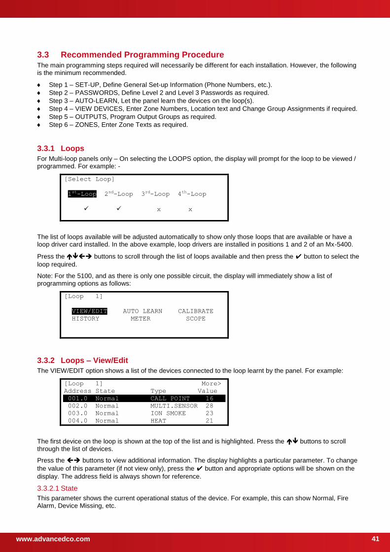
www.advancedco.com
41
3.3 Recommended Programming Procedure The main programming steps required will necessarily be different for each installation. However, the following is the minimum recommended.
Step 1 – SET-UP, Define General Set-up Information (Phone Numbers, etc.).
Step 2 – PASSWORDS, Define Level 2 and Level 3 Passwords as required.
Step 3 – AUTO-LEARN, Let the panel learn the devices on the loop(s).
Step 4 – VIEW DEVICES, Enter Zone Numbers, Location text and Change Group Assignments if required.
Step 5 – OUTPUTS, Program Output Groups as required.
Step 6 – ZONES, Enter Zone Texts as required.
3.3.1 Loops
For Multi-loop panels only – On selecting the LOOPS option, the display will prompt for the loop to be viewed / programmed. For example: -
[Select Loop]
1st-Loop 2nd-Loop 3rd-Loop 4th-Loop
x x
The list of loops available will be adjusted automatically to show only those loops that are available or have a loop driver card installed. In the above example, loop drivers are installed in positions 1 and 2 of an Mx-5400.
Press the buttons to scroll through the list of loops available and then press the button to select the
loop required.
Note: For the 5100, and as there is only one possible circuit, the display will immediately show a list of programming options as follows:
[Loop 1]
VIEW/EDIT AUTO LEARN CALIBRATE
HISTORY METER SCOPE
3.3.2 Loops – View/Edit
The VIEW/EDIT option shows a list of the devices connected to the loop learnt by the panel. For example:
[Loop 1] More>
Address State Type Value
001.0 Normal CALL POINT 16
002.0 Normal MULTI.SENSOR 28
003.0 Normal ION SMOKE 23
004.0 Normal HEAT 21
The first device on the loop is shown at the top of the list and is highlighted. Press the buttons to scroll through the list of devices.
Press the buttons to view additional information. The display highlights a particular parameter. To change
the value of this parameter (if not view only), press the button and appropriate options will be shown on the
display. The address field is always shown for reference.
3.3.2.1 State
This parameter shows the current operational status of the device. For example, this can show Normal, Fire Alarm, Device Missing, etc.
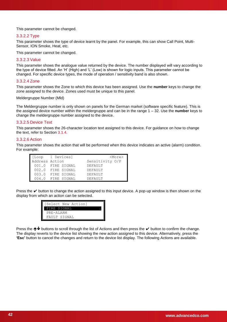
www.advancedco.com 42
This parameter cannot be changed.
3.3.2.2 Type
This parameter shows the type of device learnt by the panel. For example, this can show Call Point, Multi-Sensor, ION Smoke, Heat, etc.
This parameter cannot be changed.
3.3.2.3 Value
This parameter shows the analogue value returned by the device. The number displayed will vary according to the type of device fitted. An ‘H’ (High) and ‘L’ (Low) is shown for logic inputs. This parameter cannot be changed. For specific device types, the mode of operation / sensitivity band is also shown.
3.3.2.4 Zone
This parameter shows the Zone to which this device has been assigned. Use the number keys to change the zone assigned to the device. Zones used must be unique to this panel.
Meldergruppe Number (Mld)
The Meldergruppe number is only shown on panels for the German market (software specific feature). This is the assigned device number within the meldergruppe and can be in the range 1 – 32. Use the number keys to change the meldergruppe number assigned to the device.
3.3.2.5 Device Text
This parameter shows the 26-character location text assigned to this device. For guidance on how to change the text, refer to Section 3.1.4.
3.3.2.6 Action
This parameter shows the action that will be performed when this device indicates an active (alarm) condition. For example:
[Loop 1 Devices] <More>
Address Action Sensitivity O/P
001.0 FIRE SIGNAL DEFAULT
002.0 FIRE SIGNAL DEFAULT
003.0 FIRE SIGNAL DEFAULT
004.0 FIRE SIGNAL DEFAULT
Press the button to change the action assigned to this input device. A pop-up window is then shown on the
display from which an action can be selected.
[Select New Action]
FIRE SIGNAL .
PRE-ALARM
FAULT SIGNAL
Press the buttons to scroll through the list of Actions and then press the button to confirm the change.
The display reverts to the device list showing the new action assigned to this device. Alternatively, press the ‘Esc’ button to cancel the changes and return to the device list display. The following Actions are available.
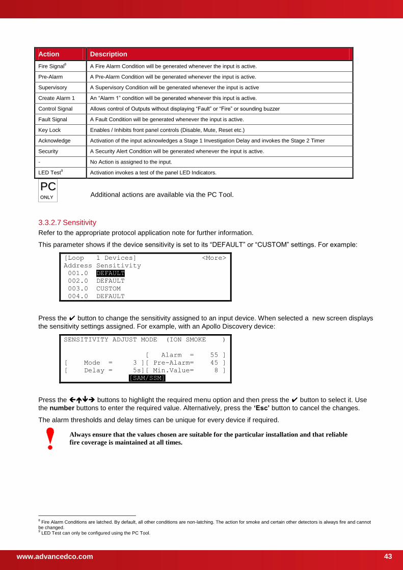
www.advancedco.com
43
Action Description
Fire Signal8 A Fire Alarm Condition will be generated whenever the input is active.
Pre-Alarm A Pre-Alarm Condition will be generated whenever the input is active.
Supervisory A Supervisory Condition will be generated whenever the input is active
Create Alarm 1 An “Alarm 1” condition will be generated whenever this input is active.
Control Signal Allows control of Outputs without displaying “Fault” or “Fire” or sounding buzzer
Fault Signal A Fault Condition will be generated whenever the input is active.
Key Lock Enables / Inhibits front panel controls (Disable, Mute, Reset etc.)
Acknowledge Activation of the input acknowledges a Stage 1 Investigation Delay and invokes the Stage 2 Timer
Security A Security Alert Condition will be generated whenever the input is active.
- No Action is assigned to the input.
LED Test9 Activation invokes a test of the panel LED Indicators.
PPCC OONNLLYY
Additional actions are available via the PC Tool.
3.3.2.7 Sensitivity
Refer to the appropriate protocol application note for further information.
This parameter shows if the device sensitivity is set to its “DEFAULT” or “CUSTOM” settings. For example:
[Loop 1 Devices] <More>
Address Sensitivity
001.0 DEFAULT
002.0 DEFAULT
003.0 CUSTOM
004.0 DEFAULT
Press the button to change the sensitivity assigned to an input device. When selected a new screen displays
the sensitivity settings assigned. For example, with an Apollo Discovery device:
SENSITIVITY ADJUST MODE (ION SMOKE )
[ Alarm = 55 ]
[ Mode = 3 ][ Pre-Alarm= 45 ]
[ Delay = 5s][ Min.Value= 8 ]
[SAM/SSM]
Press the buttons to highlight the required menu option and then press the button to select it. Use
the number buttons to enter the required value. Alternatively, press the ‘Esc’ button to cancel the changes.
The alarm thresholds and delay times can be unique for every device if required.
Always ensure that the values chosen are suitable for the particular installation and that reliable
fire coverage is maintained at all times.
8 Fire Alarm Conditions are latched. By default, all other conditions are non-latching. The action for smoke and certain other detectors is always fire and cannot
be changed. 9 LED Test can only be configured using the PC Tool.
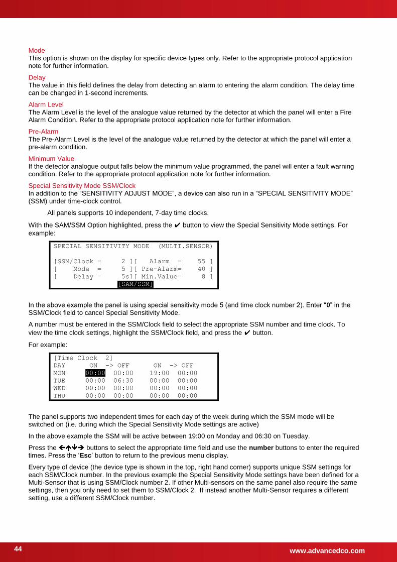
www.advancedco.com 44
Mode This option is shown on the display for specific device types only. Refer to the appropriate protocol application note for further information.
Delay The value in this field defines the delay from detecting an alarm to entering the alarm condition. The delay time can be changed in 1-second increments.
Alarm Level The Alarm Level is the level of the analogue value returned by the detector at which the panel will enter a Fire Alarm Condition. Refer to the appropriate protocol application note for further information.
Pre-Alarm The Pre-Alarm Level is the level of the analogue value returned by the detector at which the panel will enter a pre-alarm condition.
Minimum Value If the detector analogue output falls below the minimum value programmed, the panel will enter a fault warning condition. Refer to the appropriate protocol application note for further information.
Special Sensitivity Mode SSM/Clock In addition to the “SENSITIVITY ADJUST MODE”, a device can also run in a “SPECIAL SENSITIVITY MODE” (SSM) under time-clock control.
All panels supports 10 independent, 7-day time clocks.
With the SAM/SSM Option highlighted, press the button to view the Special Sensitivity Mode settings. For
example:
SPECIAL SENSITIVITY MODE (MULTI.SENSOR)
[SSM/Clock = 2 ][ Alarm = 55 ]
[ Mode = 5 ][ Pre-Alarm= 40 ]
[ Delay = 5s][ Min.Value= 8 ]
[SAM/SSM]
In the above example the panel is using special sensitivity mode 5 (and time clock number 2). Enter “0” in the SSM/Clock field to cancel Special Sensitivity Mode.
A number must be entered in the SSM/Clock field to select the appropriate SSM number and time clock. To
view the time clock settings, highlight the SSM/Clock field, and press the button.
For example:
[Time Clock 2]
DAY ON -> OFF ON -> OFF
MON 00:00 00:00 19:00 00:00
TUE 00:00 06:30 00:00 00:00
WED 00:00 00:00 00:00 00:00
THU 00:00 00:00 00:00 00:00
The panel supports two independent times for each day of the week during which the SSM mode will be switched on (i.e. during which the Special Sensitivity Mode settings are active)
In the above example the SSM will be active between 19:00 on Monday and 06:30 on Tuesday.
Press the buttons to select the appropriate time field and use the number buttons to enter the required times. Press the ‘Esc’ button to return to the previous menu display.
Every type of device (the device type is shown in the top, right hand corner) supports unique SSM settings for each SSM/Clock number. In the previous example the Special Sensitivity Mode settings have been defined for a Multi-Sensor that is using SSM/Clock number 2. If other Multi-sensors on the same panel also require the same settings, then you only need to set them to SSM/Clock 2. If instead another Multi-Sensor requires a different setting, use a different SSM/Clock number.
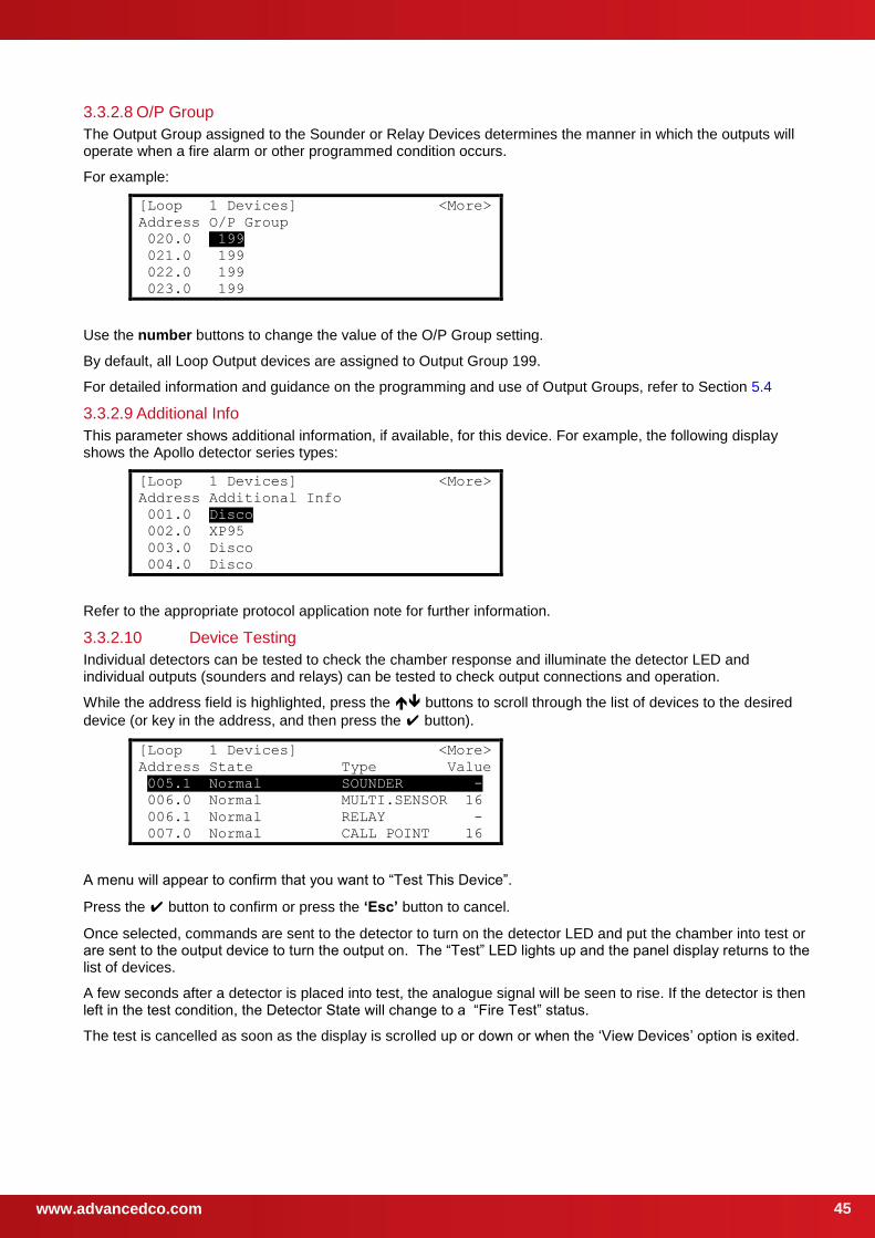
www.advancedco.com
45
3.3.2.8 O/P Group
The Output Group assigned to the Sounder or Relay Devices determines the manner in which the outputs will operate when a fire alarm or other programmed condition occurs.
For example:
[Loop 1 Devices] <More>
Address O/P Group
020.0 199
021.0 199
022.0 199
023.0 199
Use the number buttons to change the value of the O/P Group setting.
By default, all Loop Output devices are assigned to Output Group 199.
For detailed information and guidance on the programming and use of Output Groups, refer to Section 5.4
3.3.2.9 Additional Info
This parameter shows additional information, if available, for this device. For example, the following display shows the Apollo detector series types:
[Loop 1 Devices] <More>
Address Additional Info
001.0 Disco
002.0 XP95
003.0 Disco
004.0 Disco
Refer to the appropriate protocol application note for further information.
3.3.2.10 Device Testing
Individual detectors can be tested to check the chamber response and illuminate the detector LED and individual outputs (sounders and relays) can be tested to check output connections and operation.
While the address field is highlighted, press the buttons to scroll through the list of devices to the desired
device (or key in the address, and then press the button).
[Loop 1 Devices] <More>
Address State Type Value
005.1 Normal SOUNDER -
006.0 Normal MULTI.SENSOR 16
006.1 Normal RELAY -
007.0 Normal CALL POINT 16
A menu will appear to confirm that you want to “Test This Device”.
Press the button to confirm or press the ‘Esc’ button to cancel.
Once selected, commands are sent to the detector to turn on the detector LED and put the chamber into test or are sent to the output device to turn the output on. The “Test” LED lights up and the panel display returns to the list of devices.
A few seconds after a detector is placed into test, the analogue signal will be seen to rise. If the detector is then left in the test condition, the Detector State will change to a “Fire Test” status.
The test is cancelled as soon as the display is scrolled up or down or when the ‘View Devices’ option is exited.
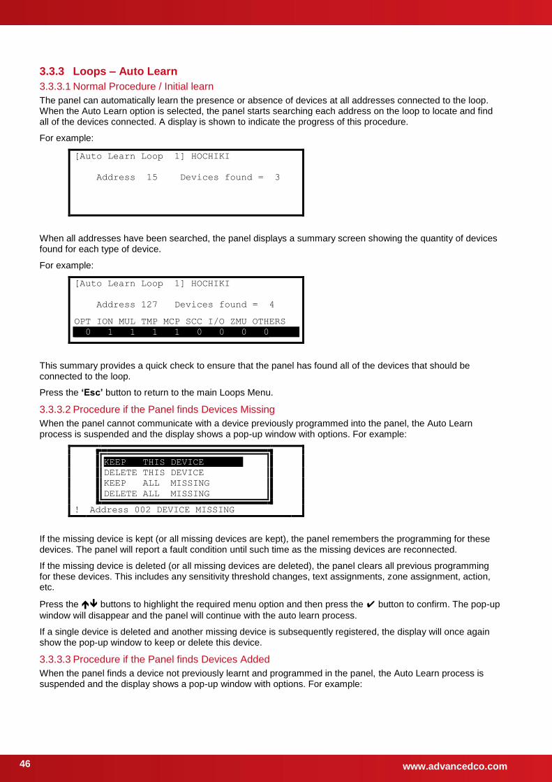
www.advancedco.com 46
3.3.3 Loops – Auto Learn
3.3.3.1 Normal Procedure / Initial learn
The panel can automatically learn the presence or absence of devices at all addresses connected to the loop. When the Auto Learn option is selected, the panel starts searching each address on the loop to locate and find all of the devices connected. A display is shown to indicate the progress of this procedure.
For example:
[Auto Learn Loop 1] HOCHIKI
Address 15 Devices found = 3
When all addresses have been searched, the panel displays a summary screen showing the quantity of devices found for each type of device.
For example:
[Auto Learn Loop 1] HOCHIKI
Address 127 Devices found = 4
OPT ION MUL TMP MCP SCC I/O ZMU OTHERS
0 1 1 1 1 0 0 0 0
This summary provides a quick check to ensure that the panel has found all of the devices that should be connected to the loop.
Press the ‘Esc’ button to return to the main Loops Menu.
3.3.3.2 Procedure if the Panel finds Devices Missing
When the panel cannot communicate with a device previously programmed into the panel, the Auto Learn process is suspended and the display shows a pop-up window with options. For example:
KEEP THIS DEVICE .
DELETE THIS DEVICE
KEEP ALL MISSING
DELETE ALL MISSING
! Address 002 DEVICE MISSING
If the missing device is kept (or all missing devices are kept), the panel remembers the programming for these devices. The panel will report a fault condition until such time as the missing devices are reconnected.
If the missing device is deleted (or all missing devices are deleted), the panel clears all previous programming for these devices. This includes any sensitivity threshold changes, text assignments, zone assignment, action, etc.
Press the buttons to highlight the required menu option and then press the button to confirm. The pop-up
window will disappear and the panel will continue with the auto learn process.
If a single device is deleted and another missing device is subsequently registered, the display will once again show the pop-up window to keep or delete this device.
3.3.3.3 Procedure if the Panel finds Devices Added
When the panel finds a device not previously learnt and programmed in the panel, the Auto Learn process is suspended and the display shows a pop-up window with options. For example:
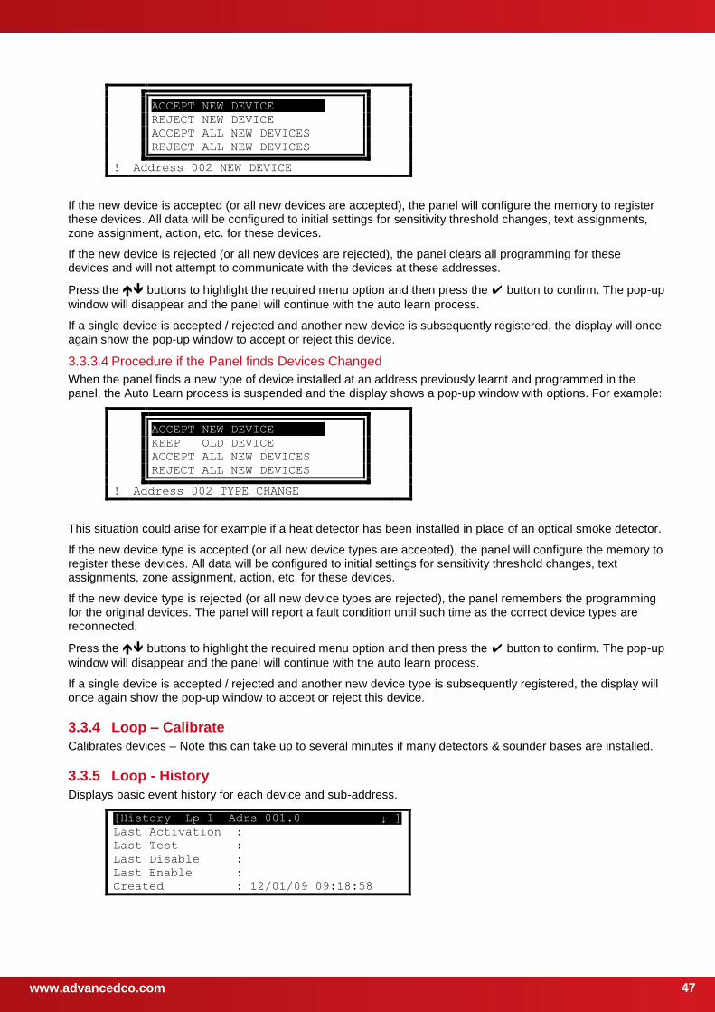
www.advancedco.com
47
ACCEPT NEW DEVICE .
REJECT NEW DEVICE
ACCEPT ALL NEW DEVICES
REJECT ALL NEW DEVICES
! Address 002 NEW DEVICE
If the new device is accepted (or all new devices are accepted), the panel will configure the memory to register these devices. All data will be configured to initial settings for sensitivity threshold changes, text assignments, zone assignment, action, etc. for these devices.
If the new device is rejected (or all new devices are rejected), the panel clears all programming for these devices and will not attempt to communicate with the devices at these addresses.
Press the buttons to highlight the required menu option and then press the button to confirm. The pop-up
window will disappear and the panel will continue with the auto learn process.
If a single device is accepted / rejected and another new device is subsequently registered, the display will once again show the pop-up window to accept or reject this device.
3.3.3.4 Procedure if the Panel finds Devices Changed
When the panel finds a new type of device installed at an address previously learnt and programmed in the panel, the Auto Learn process is suspended and the display shows a pop-up window with options. For example:
ACCEPT NEW DEVICE .
KEEP OLD DEVICE
ACCEPT ALL NEW DEVICES
REJECT ALL NEW DEVICES
! Address 002 TYPE CHANGE
This situation could arise for example if a heat detector has been installed in place of an optical smoke detector.
If the new device type is accepted (or all new device types are accepted), the panel will configure the memory to register these devices. All data will be configured to initial settings for sensitivity threshold changes, text assignments, zone assignment, action, etc. for these devices.
If the new device type is rejected (or all new device types are rejected), the panel remembers the programming for the original devices. The panel will report a fault condition until such time as the correct device types are reconnected.
Press the buttons to highlight the required menu option and then press the button to confirm. The pop-up
window will disappear and the panel will continue with the auto learn process.
If a single device is accepted / rejected and another new device type is subsequently registered, the display will once again show the pop-up window to accept or reject this device.
3.3.4 Loop – Calibrate
Calibrates devices – Note this can take up to several minutes if many detectors & sounder bases are installed.
3.3.5 Loop - History
Displays basic event history for each device and sub-address.
[History Lp 1 Adrs 001.0 ↓ ]
Last Activation :
Last Test :
Last Disable :
Last Enable :
Created : 12/01/09 09:18:58

www.advancedco.com 48
Item Description
Last Activation The date and time that the device was last activated (e.g. smoke level detected is at pre-alarm or alarm levels or the last time that an output was turned on).
Last Test The date and time that the device was last tested (e.g. smoke level detected is at pre-alarm or alarm levels or the last time that an output was turned on).
Last Disable The date and time that the device was last disabled.
Last Enable The date and time that the device was last re-enabled.
Created The date and time that the device was either auto-learnt at the panel or added to the device list from a PC configuration.
3.3.6 Loop – Meter
Displays loop output and input voltages and loop loading.
A diagnostic display with automatic scanning of the loop to find devices with minimum and maximum communication pulse heights is available.
3.3.7 Loop – Scope
This function displays the loop input and output voltage and current measurements in the form of a waveform. Refer to separate application note (680-505) for details of this feature.
10.0V/ 2.0mS/ 0μS
0V
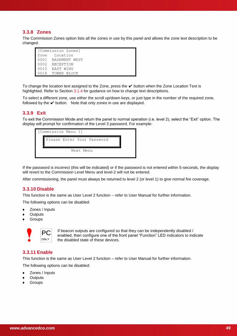
www.advancedco.com
49
3.3.8 Zones
The Commission Zones option lists all the zones in use by this panel and allows the zone text description to be changed.
[Commission Zones]
Zone Location
0001 BASEMENT WEST
0002 RECEPTION
0015 EAST WING
0018 TOWER BLOCK
To change the location text assigned to the Zone, press the button when the Zone Location Text is
highlighted. Refer to Section 3.1.4 for guidance on how to change text descriptions.
To select a different zone, use either the scroll up/down keys, or just type in the number of the required zone,
followed by the button. Note that only zones in use are displayed.
3.3.9 Exit
To exit the Commission Mode and return the panel to normal operation (i.e. level 2), select the “Exit” option. The display will prompt for confirmation of the Level 3 password. For example:
[Commission Menu 1]
Please Enter Your Password
Next Menu
If the password is incorrect (this will be indicated) or if the password is not entered within 5-seconds, the display will revert to the Commission Level Menu and level-2 will not be entered.
After commissioning, the panel must always be returned to level 2 (or level 1) to give normal fire coverage.
3.3.10 Disable
This function is the same as User Level 2 function – refer to User Manual for further information.
The following options can be disabled:
Zones / Inputs
Outputs
Groups
PPCC OONNLLYY
If beacon outputs are configured so that they can be independently disabled / enabled, then configure one of the front panel “Function” LED indicators to indicate the disabled state of these devices.
3.3.11 Enable
This function is the same as User Level 2 function – refer to User Manual for further information.
The following options can be disabled:
Zones / Inputs
Outputs
Groups
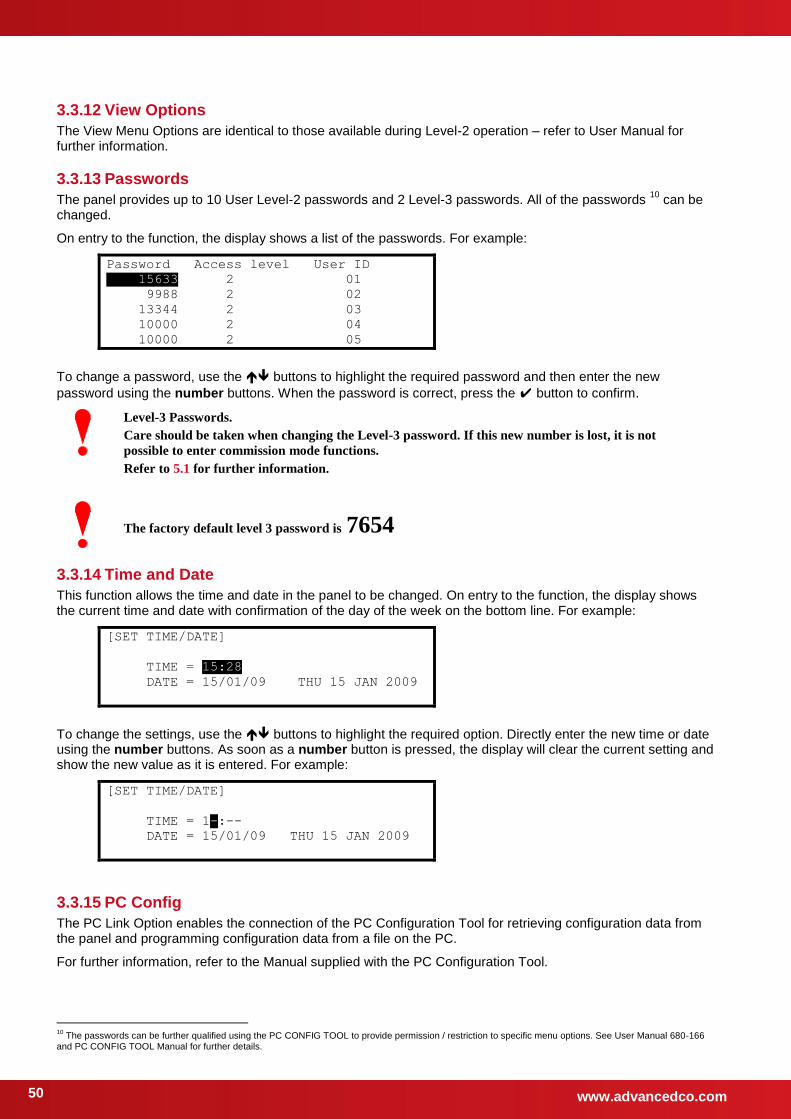
www.advancedco.com 50
3.3.12 View Options
The View Menu Options are identical to those available during Level-2 operation – refer to User Manual for further information.
3.3.13 Passwords
The panel provides up to 10 User Level-2 passwords and 2 Level-3 passwords. All of the passwords 10
can be changed.
On entry to the function, the display shows a list of the passwords. For example:
Password Access level User ID
15633 2 01
9988 2 02
13344 2 03
10000 2 04
10000 2 05
To change a password, use the buttons to highlight the required password and then enter the new
password using the number buttons. When the password is correct, press the button to confirm.
Level-3 Passwords.
Care should be taken when changing the Level-3 password. If this new number is lost, it is not
possible to enter commission mode functions.
Refer to 5.1 for further information.
The factory default level 3 password is 7654
3.3.14 Time and Date
This function allows the time and date in the panel to be changed. On entry to the function, the display shows the current time and date with confirmation of the day of the week on the bottom line. For example:
[SET TIME/DATE]
TIME = 15:28
DATE = 15/01/09 THU 15 JAN 2009
To change the settings, use the buttons to highlight the required option. Directly enter the new time or date using the number buttons. As soon as a number button is pressed, the display will clear the current setting and show the new value as it is entered. For example:
[SET TIME/DATE]
TIME = 1-:--
DATE = 15/01/09 THU 15 JAN 2009
3.3.15 PC Config
The PC Link Option enables the connection of the PC Configuration Tool for retrieving configuration data from the panel and programming configuration data from a file on the PC.
For further information, refer to the Manual supplied with the PC Configuration Tool.
10
The passwords can be further qualified using the PC CONFIG TOOL to provide permission / restriction to specific menu options. See User Manual 680-166 and PC CONFIG TOOL Manual for further details.
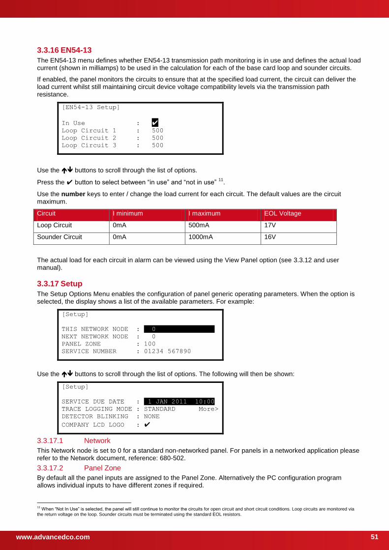
www.advancedco.com
51
3.3.16 EN54-13
The EN54-13 menu defines whether EN54-13 transmission path monitoring is in use and defines the actual load current (shown in milliamps) to be used in the calculation for each of the base card loop and sounder circuits.
If enabled, the panel monitors the circuits to ensure that at the specified load current, the circuit can deliver the load current whilst still maintaining circuit device voltage compatibility levels via the transmission path resistance.
[EN54-13 Setup]
In Use : Loop Circuit 1 : 500
Loop Circuit 2 : 500
Loop Circuit 3 : 500
Use the buttons to scroll through the list of options.
Press the button to select between “in use” and “not in use” 11
.
Use the number keys to enter / change the load current for each circuit. The default values are the circuit maximum.
Circuit I minimum I maximum EOL Voltage
Loop Circuit 0mA 500mA 17V
Sounder Circuit 0mA 1000mA 16V
The actual load for each circuit in alarm can be viewed using the View Panel option (see 3.3.12 and user manual).
3.3.17 Setup
The Setup Options Menu enables the configuration of panel generic operating parameters. When the option is selected, the display shows a list of the available parameters. For example:
[Setup]
THIS NETWORK NODE : . 0 .
NEXT NETWORK NODE : 0
PANEL ZONE : 100
SERVICE NUMBER : 01234 567890
Use the buttons to scroll through the list of options. The following will then be shown:
[Setup]
SERVICE DUE DATE : 01 JAN 2011 10:00
TRACE LOGGING MODE : STANDARD More>
DETECTOR BLINKING : NONE
COMPANY LCD LOGO :
3.3.17.1 Network
This Network node is set to 0 for a standard non-networked panel. For panels in a networked application please refer to the Network document, reference: 680-502.
3.3.17.2 Panel Zone
By default all the panel inputs are assigned to the Panel Zone. Alternatively the PC configuration program allows individual inputs to have different zones if required.
11
When “Not In Use” is selected, the panel will still continue to monitor the circuits for open circuit and short circuit conditions. Loop circuits are monitored via the return voltage on the loop. Sounder circuits must be terminated using the standard EOL resistors.
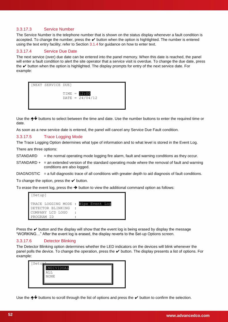
www.advancedco.com 52
3.3.17.3 Service Number
The Service Number is the telephone number that is shown on the status display whenever a fault condition is
accepted. To change the number, press the button when the option is highlighted. The number is entered
using the text entry facility; refer to Section 3.1.4 for guidance on how to enter text.
3.3.17.4 Service Due Date
The next service (over) due date can be entered into the panel memory. When this date is reached, the panel will enter a fault condition to alert the site operator that a service visit is overdue. To change the due date, press
the button when the option is highlighted. The display prompts for entry of the next service date. For
example:
[NEXT SERVICE DUE]
TIME = 12:00
DATE = 24/04/12
Use the buttons to select between the time and date. Use the number buttons to enter the required time or date.
As soon as a new service date is entered, the panel will cancel any Service Due Fault condition.
3.3.17.5 Trace Logging Mode
The Trace Logging Option determines what type of information and to what level is stored in the Event Log.
There are three options:
STANDARD = the normal operating mode logging fire alarm, fault and warning conditions as they occur.
STANDARD + = an extended version of the standard operating mode where the removal of fault and warning conditions are also logged.
DIAGNOSTIC = a full diagnostic trace of all conditions with greater depth to aid diagnosis of fault conditions.
To change the option, press the button.
To erase the event log, press the button to view the additional command option as follows:
[Setup]
TRACE LOGGING MODE : Wipe Event Log
DETECTOR BLINKING :
COMPANY LCD LOGO :
PROGRAM ID :
Press the button and the display will show that the event log is being erased by display the message
“WORKING…” After the event log is erased, the display reverts to the Set-up Options screen.
3.3.17.6 Detector Blinking
The Detector Blinking option determines whether the LED indicators on the devices will blink whenever the
panel polls the device. To change the operation, press the button. The display presents a list of options. For
example:
[Setup]
Use the buttons to scroll through the list of options and press the button to confirm the selection.
INDIVIDUAL
ALL
NONE
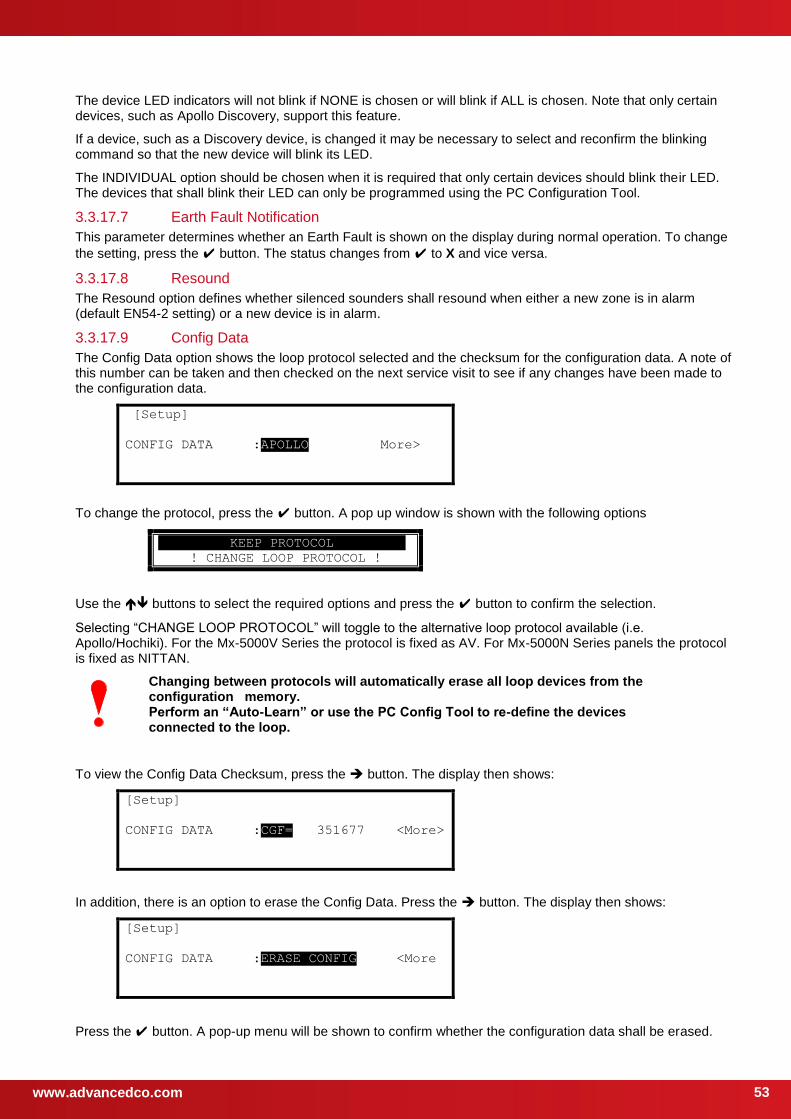
www.advancedco.com
53
The device LED indicators will not blink if NONE is chosen or will blink if ALL is chosen. Note that only certain devices, such as Apollo Discovery, support this feature.
If a device, such as a Discovery device, is changed it may be necessary to select and reconfirm the blinking command so that the new device will blink its LED.
The INDIVIDUAL option should be chosen when it is required that only certain devices should blink their LED. The devices that shall blink their LED can only be programmed using the PC Configuration Tool.
3.3.17.7 Earth Fault Notification
This parameter determines whether an Earth Fault is shown on the display during normal operation. To change
the setting, press the button. The status changes from to X and vice versa.
3.3.17.8 Resound
The Resound option defines whether silenced sounders shall resound when either a new zone is in alarm (default EN54-2 setting) or a new device is in alarm.
3.3.17.9 Config Data
The Config Data option shows the loop protocol selected and the checksum for the configuration data. A note of this number can be taken and then checked on the next service visit to see if any changes have been made to the configuration data.
[Setup]
CONFIG DATA :APOLLO More>
To change the protocol, press the button. A pop up window is shown with the following options
. KEEP PROTOCOL .
! CHANGE LOOP PROTOCOL !
Use the buttons to select the required options and press the button to confirm the selection.
Selecting “CHANGE LOOP PROTOCOL” will toggle to the alternative loop protocol available (i.e. Apollo/Hochiki). For the Mx-5000V Series the protocol is fixed as AV. For Mx-5000N Series panels the protocol is fixed as NITTAN.
Changing between protocols will automatically erase all loop devices from the configuration memory. Perform an “Auto-Learn” or use the PC Config Tool to re-define the devices connected to the loop.
To view the Config Data Checksum, press the button. The display then shows:
[Setup]
CONFIG DATA :CGF= 351677 <More>
In addition, there is an option to erase the Config Data. Press the button. The display then shows:
[Setup]
CONFIG DATA :ERASE CONFIG <More
Press the button. A pop-up menu will be shown to confirm whether the configuration data shall be erased.
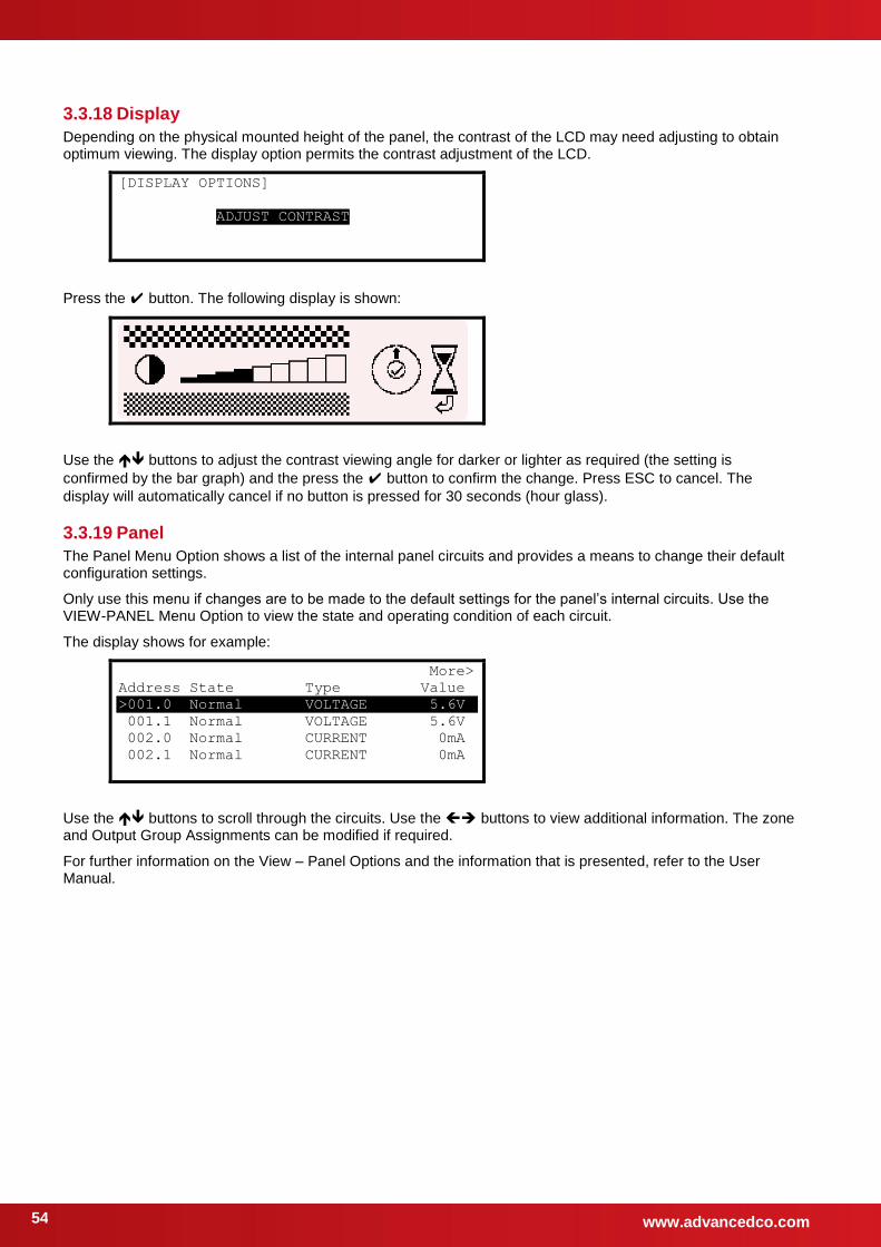
www.advancedco.com 54
3.3.18 Display
Depending on the physical mounted height of the panel, the contrast of the LCD may need adjusting to obtain optimum viewing. The display option permits the contrast adjustment of the LCD.
[DISPLAY OPTIONS]
ADJUST CONTRAST
Press the button. The following display is shown:
Use the buttons to adjust the contrast viewing angle for darker or lighter as required (the setting is
confirmed by the bar graph) and the press the button to confirm the change. Press ESC to cancel. The
display will automatically cancel if no button is pressed for 30 seconds (hour glass).
3.3.19 Panel
The Panel Menu Option shows a list of the internal panel circuits and provides a means to change their default configuration settings.
Only use this menu if changes are to be made to the default settings for the panel’s internal circuits. Use the VIEW-PANEL Menu Option to view the state and operating condition of each circuit.
The display shows for example:
More>
Address State Type Value
>001.0 Normal VOLTAGE 5.6V
001.1 Normal VOLTAGE 5.6V
002.0 Normal CURRENT 0mA
002.1 Normal CURRENT 0mA
Use the buttons to scroll through the circuits. Use the buttons to view additional information. The zone and Output Group Assignments can be modified if required.
For further information on the View – Panel Options and the information that is presented, refer to the User Manual.
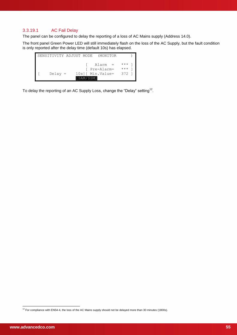
www.advancedco.com
55
3.3.19.1 AC Fail Delay
The panel can be configured to delay the reporting of a loss of AC Mains supply (Address 14.0).
The front panel Green Power LED will still immediately flash on the loss of the AC Supply, but the fault condition is only reported after the delay time (default 10s) has elapsed.
SENSITIVITY ADJUST MODE (MONITOR )
[ Alarm = *** ]
[ Pre-Alarm= *** ]
[ Delay = 10s][ Min.Value= 372 ]
[SAM/SSM]
To delay the reporting of an AC Supply Loss, change the “Delay” setting12
.
12
For compliance with EN54-4, the loss of the AC Mains supply should not be delayed more than 30 minutes (1800s).
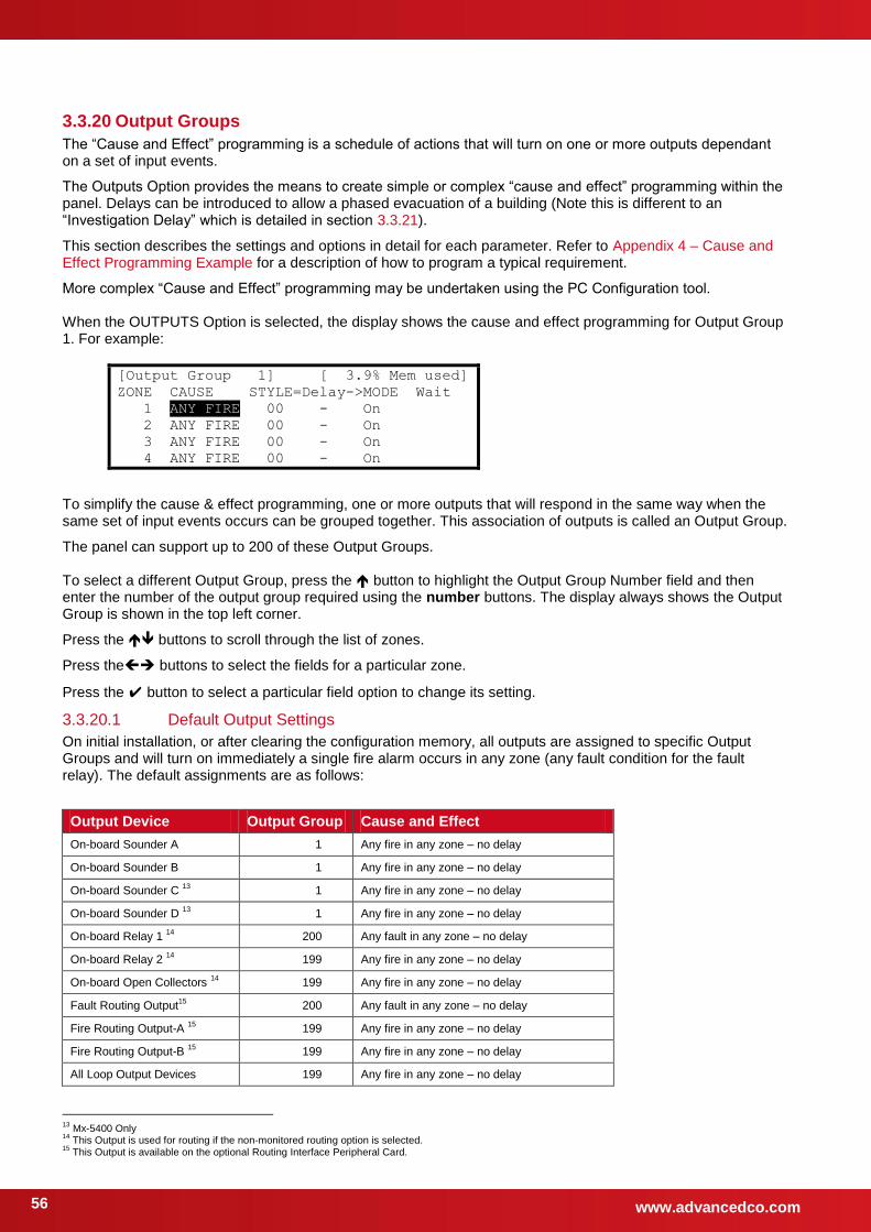
www.advancedco.com 56
3.3.20 Output Groups
The “Cause and Effect” programming is a schedule of actions that will turn on one or more outputs dependant on a set of input events.
The Outputs Option provides the means to create simple or complex “cause and effect” programming within the panel. Delays can be introduced to allow a phased evacuation of a building (Note this is different to an “Investigation Delay” which is detailed in section 3.3.21).
This section describes the settings and options in detail for each parameter. Refer to Appendix 4 – Cause and Effect Programming Example for a description of how to program a typical requirement.
More complex “Cause and Effect” programming may be undertaken using the PC Configuration tool. When the OUTPUTS Option is selected, the display shows the cause and effect programming for Output Group 1. For example:
[Output Group 1] [ 3.9% Mem used]
ZONE CAUSE STYLE=Delay->MODE Wait
1 ANY FIRE 00 - On
2 ANY FIRE 00 - On
3 ANY FIRE 00 - On
4 ANY FIRE 00 - On
To simplify the cause & effect programming, one or more outputs that will respond in the same way when the same set of input events occurs can be grouped together. This association of outputs is called an Output Group.
The panel can support up to 200 of these Output Groups. To select a different Output Group, press the button to highlight the Output Group Number field and then enter the number of the output group required using the number buttons. The display always shows the Output Group is shown in the top left corner.
Press the buttons to scroll through the list of zones.
Press the buttons to select the fields for a particular zone.
Press the button to select a particular field option to change its setting.
3.3.20.1 Default Output Settings
On initial installation, or after clearing the configuration memory, all outputs are assigned to specific Output Groups and will turn on immediately a single fire alarm occurs in any zone (any fault condition for the fault relay). The default assignments are as follows:
Output Device Output Group Cause and Effect
On-board Sounder A 1 Any fire in any zone – no delay
On-board Sounder B 1 Any fire in any zone – no delay
On-board Sounder C 13
1 Any fire in any zone – no delay
On-board Sounder D 13
1 Any fire in any zone – no delay
On-board Relay 1 14
200 Any fault in any zone – no delay
On-board Relay 2 14
199 Any fire in any zone – no delay
On-board Open Collectors 14
199 Any fire in any zone – no delay
Fault Routing Output15
200 Any fault in any zone – no delay
Fire Routing Output-A 15
199 Any fire in any zone – no delay
Fire Routing Output-B 15
199 Any fire in any zone – no delay
All Loop Output Devices 199 Any fire in any zone – no delay
13
Mx-5400 Only 14
This Output is used for routing if the non-monitored routing option is selected. 15
This Output is available on the optional Routing Interface Peripheral Card.
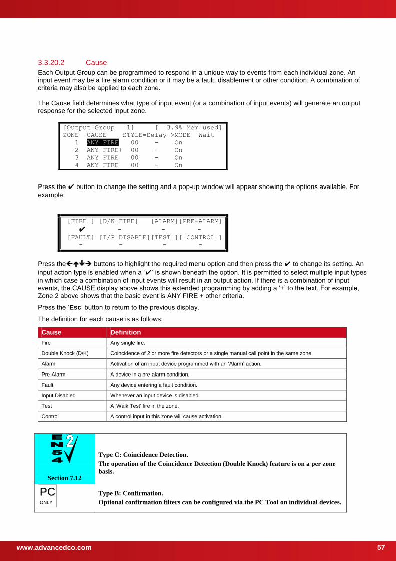
www.advancedco.com
57
3.3.20.2 Cause
Each Output Group can be programmed to respond in a unique way to events from each individual zone. An input event may be a fire alarm condition or it may be a fault, disablement or other condition. A combination of criteria may also be applied to each zone. The Cause field determines what type of input event (or a combination of input events) will generate an output response for the selected input zone.
[Output Group 1] [ 3.9% Mem used]
ZONE CAUSE STYLE=Delay->MODE Wait
1 ANY FIRE 00 - On
2 ANY FIRE+ 00 - On
3 ANY FIRE 00 - On
4 ANY FIRE 00 - On
Press the button to change the setting and a pop-up window will appear showing the options available. For
example:
[FIRE ] [D/K FIRE] [ALARM][PRE-ALARM]
- - -
[FAULT] [I/P DISABLE][TEST ][ CONTROL ]
- - - -
Press the buttons to highlight the required menu option and then press the to change its setting. An
input action type is enabled when a ‘’ is shown beneath the option. It is permitted to select multiple input types
in which case a combination of input events will result in an output action. If there is a combination of input events, the CAUSE display above shows this extended programming by adding a ‘+’ to the text. For example, Zone 2 above shows that the basic event is ANY FIRE + other criteria.
Press the ‘Esc’ button to return to the previous display.
The definition for each cause is as follows:
Cause Definition
Fire Any single fire.
Double Knock (D/K) Coincidence of 2 or more fire detectors or a single manual call point in the same zone.
Alarm Activation of an input device programmed with an ‘Alarm’ action.
Pre-Alarm A device in a pre-alarm condition.
Fault Any device entering a fault condition.
Input Disabled Whenever an input device is disabled.
Test A 'Walk Test' fire in the zone.
Control A control input in this zone will cause activation.
Section 7.12
Type C: Coincidence Detection.
The operation of the Coincidence Detection (Double Knock) feature is on a per zone
basis.
PPCC OONNLLYY
Type B: Confirmation.
Optional confirmation filters can be configured via the PC Tool on individual devices.

www.advancedco.com 58
3.3.20.3 Style
The way in which an output turns on in response to a particular input event can be programmed. For example, an output may turn on immediately, it may turn on after a delay or it may pulse for a set time and then turn on. This method of operation is called a Style. A style may have up to three different methods of operation. For example,
Delay Mode, Wait Mode, Wait Mode.
Style 00 is fixed to turn on immediately an input event occurs.
Style 01 is fixed to pulse immediately an input event occurs.
Styles 02 to 20 are programmable.
Press the button to step on to the style field. Change the setting using number entry to select the required output style. If the style is already programmed elsewhere, the relevant style parameters are automatically entered into the appropriate fields.
3.3.20.4 Delay
The delay field is the time from qualification of the input event to something happening at the output. The delay time can be set in intervals of 1 second up to a maximum of 250 seconds.
Press the button to step on to the delay field and change the setting using number entry.
3.3.20.5 Mode
The mode field defines the method of operation of the output when it is first activated. This can be ON or PULSE.
Press the button to step on to the delay field and change the setting using the button.
Note: Pulse settings are by default 1-second ON / 1-second OFF. Other pulse options can be specified on the PC Tool (such as 2s ON / 3s OFF) – these can be assigned to on-board outputs only.
3.3.20.6 Wait
The wait field is the time from first activation of the output to the next operational condition (mode) of the output. For example, the output could initially be delayed for 20 seconds and turn on in a pulsing mode. After a wait of a further 30 seconds it can be programmed to turn on differently such as ON. The wait time can be set in intervals of 1 second up to a maximum of 250 seconds.
Press the button to step on to the wait field and change the setting using number entry.
3.3.20.7 Copying Output Settings to Multiple Zones
To save time in the entry of similar Output Group Settings for each zone, it is possible to copy information programmed for a particular zone to subsequent zones.
Press the button to highlight the required zone number and then press the button. The display shows a
pop-up window prompting for the number of the zone to which to copy the information.
Use the number entry to select the required zone number. The Output Group programming for all of the zones from the currently selected zone to the zone number entered will be programmed with the same information as the currently selected zone.
3.3.21 Investigation Delays
PPCC OONNLLYY
In addition to the “Cause and Effect” programming described above, the panels also support an “Investigation Delay Mode” which allows time for a building supervisor to investigate fire signals before turning outputs on. This mode can only be configured from the PC software.
There are two parts to this delay. The first stage is set relatively short. If the building supervisor does not acknowledge the fire signal within the first stage, the delayed outputs will turn on. The second stage gives a longer period to investigate the fire signal. This delay can be cancelled at any time by pressing the EVACUATE button, or any nominated input devices (by default, all call points cancel this mode).
Each input and output device can be individually programmed to use the investigation delay from the PC configuration software, together with the times appropriate to each stage of the delay. The user manual gives details of how the building occupier can turn the investigation delay feature on or off.

www.advancedco.com
59
Section 7.11
Delays to Outputs.
It must be possible to override the operation of any delays at Level 1. Refer to Section
3.3.21.1 for information on overriding delays.
For compliance, the maximum total delay permitted is 10 minutes.
3.3.21.1 Overriding Delays at Level 1
A facility to override any programmed delays and immediately activate the sounder circuits should be provided at Level 1. It is possible to override the delay using the panel controls (see the user manual for details). This can also be achieved from an input device (such as a manual call point) that is programmed to turn on all outputs immediately.
3.3.22 Test
This function is the same as User Level 2 function – refer to User Manual for further information.
The following functions can be tested:
Zones / Inputs
Display
Buzzer
Printer
Outputs
3.3.23 LED Indications
This option is not provided from Software Version 050-04.
The operation of all MXP-513-XXX LED Indicator Cards MUST be configured using the PC Tool.
Panels equipped with integral panel LED indicators on the display card will default to indicate fire alarms in Zones 1-20. The operation of these can be adjusted using the PC Tool.
PPCC OONNLLYY
Each LED can be individually configured via the PC Tool to either zone assignment, output group assignment or other function.
www.advancedco.com 60
4 Service and Maintenance
4.1 Maintenance Schedule
This equipment should be maintained in accordance with the regulations and codes appropriate to the country and location of installation. The following is recommended if no other regulations apply.
4.1.1 Daily Actions
The site operator / user should perform the following checks and actions:
a) The panel indicates normal operation. If any faults exist, these should be recorded in a logbook.
b) Any recorded faults have received attention and have been signed off.
4.1.2 Monthly Actions
The site operator / user should perform the following checks and actions:
a) Any stand-by generators should be started and fuel levels checked.
b) Operate at least one call point or detector (from different zones each month) and check that the panel enters a fire alarm condition and that the appropriate / programmed alarm or warning devices are sounded / operated. Where permissible, this should include any links to the fire brigade or remote centre.
c) Check that all outstanding faults have been recorded and have received attention.
4.1.3 Quarterly Actions
The service / maintenance contractor should perform the following checks and actions:
a) Check that all entries in the logbook have been addressed, check the event log in the panel and take the necessary remedial actions.
b) Visually inspect the panel for any moisture ingress or other deterioration, check all battery connections and test / check the alarm, fault and other functions of the panel operation.
c) Ascertain if any building or structural alterations have been carried out that would affect the placement / location of call points or detectors. If so, perform a visual inspection.
d) Record in the logbook any defects or remedial actions that must be undertaken and arrange for these to be carried out as soon as possible.
4.1.4 Annual Actions
The service / maintenance contractor should perform the following checks and actions:
a) Perform the checks as recommended above in the daily, monthly and quarterly schedules.
b) Perform a complete “Walk Test” of the system to check that each call point and detector is operating to its manufacturers’ specification.
c) Visually inspect all cable fittings. Check that the equipment is undamaged and that the conditions of installation have not changed such that they fall outside of the equipment specifications.
d) Inspect and test all batteries and replace as required – refer to Section 4.2 for recommended replacement schedule.
e) Record in the logbook any defects or remedial actions that must be undertaken and arrange for these to be carried out as soon as possible.

www.advancedco.com
61
4.2 Replacement of Components In general, all of the components parts used in the construction of the panel have been selected for long life and reliability.
However, certain components may require to be changed on a regular service basis. The details of these are as follows:
4.2.1 Batteries
For battery installation, see section 2.5.2
Respect the Environment.
Batteries must be disposed of responsibly and in accordance with any local
regulations.
4.2.1.1 Standby Batteries
Expected Life: - 3-5 years at an ambient temperature of 20°C
Replacement Schedule: - As above. However, note that the expected battery life is shortened by increase in ambient temperature. The life reduces by 50% for every 10°C rise above ambient. Refer to battery manufacturer for further information.
Manufacturer / Part Numbers: - YUASA POWERSONIC
4AH NP4-12 5AH PS-1250
7AH NP7-12 7AH PS-1270
12AH NP12-12 12AH PS-12110
17AH NP18-12 18AH PS-12170
24AH NP24-12B 26AH PS-12260
38AH NP24-38 38AH PS-12380
45AH PS-12450
STOP
For optimum performance and charge retention, Yuasa recommend that batteries are ‘top-charged’ prior to installation.
For batteries up to 6 months old from date of manufacture, charge at 2.4V per cell (i.e. 14.4V per battery) for 20 hours prior to installing the batteries.
It is not recommended to use batteries that are more than 6 months old, from their date of manufacture, on a new installation.
It is quite normal for lead-acid batteries to vent hydrogen when being charged.
The panel is adequately ventilated to dissipate this hydrogen. DO NOT seal the enclosure or install in a sealed enclosure or cavity.
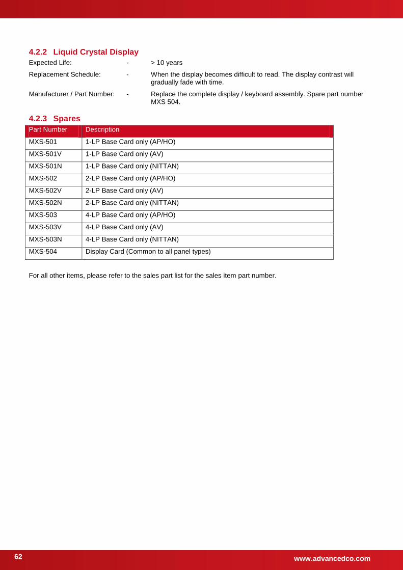
www.advancedco.com 62
4.2.2 Liquid Crystal Display
Expected Life: - > 10 years
Replacement Schedule: - When the display becomes difficult to read. The display contrast will gradually fade with time.
Manufacturer / Part Number: - Replace the complete display / keyboard assembly. Spare part number MXS 504.
4.2.3 Spares
Part Number Description
MXS-501 1-LP Base Card only (AP/HO)
MXS-501V 1-LP Base Card only (AV)
MXS-501N 1-LP Base Card only (NITTAN)
MXS-502 2-LP Base Card only (AP/HO)
MXS-502V 2-LP Base Card only (AV)
MXS-502N 2-LP Base Card only (NITTAN)
MXS-503 4-LP Base Card only (AP/HO)
MXS-503V 4-LP Base Card only (AV)
MXS-503N 4-LP Base Card only (NITTAN)
MXS-504 Display Card (Common to all panel types)
For all other items, please refer to the sales part list for the sales item part number.
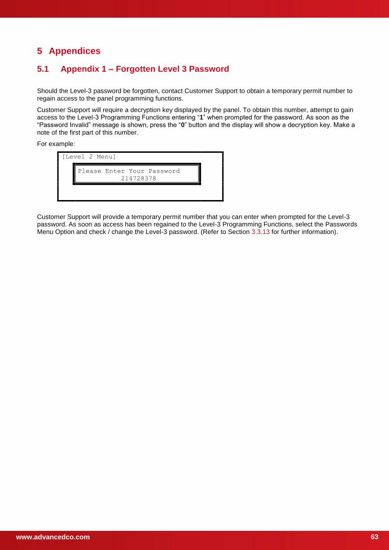
www.advancedco.com
63
5 Appendices
5.1 Appendix 1 – Forgotten Level 3 Password
Should the Level-3 password be forgotten, contact Customer Support to obtain a temporary permit number to regain access to the panel programming functions.
Customer Support will require a decryption key displayed by the panel. To obtain this number, attempt to gain access to the Level-3 Programming Functions entering “1” when prompted for the password. As soon as the “Password Invalid” message is shown, press the “0” button and the display will show a decryption key. Make a note of the first part of this number.
For example:
[Level 2 Menu]
Please Enter Your Password
214728378
Customer Support will provide a temporary permit number that you can enter when prompted for the Level-3 password. As soon as access has been regained to the Level-3 Programming Functions, select the Passwords Menu Option and check / change the Level-3 password. (Refer to Section 3.3.13 for further information).
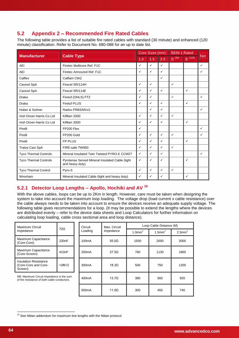
www.advancedco.com 64
5.2 Appendix 2 – Recommended Fire Rated Cables The following table provides a list of suitable fire rated cables with standard (30 minute) and enhanced (120 minute) classification. Refer to Document No. 680-088 for an up to date list.
Manufacturer Cable Type Core Sizes (mm) 5839-1 Rated
Net 1.0 1.5 2.5 S
(30) E
(120)
AEI Firetec Multicore Ref. F1C
AEI Firetec Armoured Ref. F1C
Calflex Calflam CWZ (2.5mm2)
Cavicel SpA Firecel SR/114H
Cavicel SpA Firecel SR/114E
Draka Firetuf (OHLS) FTZ
Draka Firetuf PLUS
Huber & Suhner Radox FRBS/M1x2
Irish Driver-Harris Co Ltd Kilflam 2000
Irish Driver-Harris Co Ltd Kilflam 3000
Pirelli FP200 Flex (1.0mm2)
Pirelli FP200 Gold (1.0mm2)
Pirelli FP PLUS
Tratos Cavi SpA FIRE-safe TW950
Tyco Thermal Controls Mineral Insulated Twin Twisted PYRO-E CCM2T
Tyco Thermal Controls Pyrotenax Served Mineral Insulated Cable (light and heavy duty)
Tyco Thermal Control Pyro-S
Wrexham Mineral Insulated Cable (light and heavy duty)
5.2.1 Detector Loop Lengths – Apollo, Hochiki and AV 16
With the above cables, loops can be up to 2Km in length. However, care must be taken when designing the system to take into account the maximum loop loading. The voltage drop (load current x cable resistance) over the cable always needs to be taken into account to ensure the devices receive an adequate supply voltage. The following table gives recommendations for a loop. (It may be possible to extend the lengths where the devices are distributed evenly – refer to the device data sheets and Loop Calculators for further information on calculating loop loading, cable cross sectional area and loop distance).
Maximum Circuit Impedance
72Ω Circuit Loading
Max. Circuit Impedance
Loop Cable Distance (M)
1.0mm2 1.5mm
2 2.5mm
2
Maximum Capacitance (Core-Core)
230nF 100mA 55.0Ω 1500 2000 2000
Maximum Capacitance (Core-Screen)
410nF 200mA 27.5Ω 760 1130 1860
Insulation Resistance (Core-Core and Core-Screen)
>2M Ω 300mA 18.3Ω 500 750 1200
NB: Maximum Circuit Impedence is the sum of the resistance of both cable conductors.
400mA 13.7Ω 380 560 920
500mA 11.0Ω 300 450 740
16
See Nittan addendum for maximum line lengths with the Nittan protocol

www.advancedco.com
65
5.2.2 Sounder Circuit Lengths
The voltage drop on each alarm circuit should be calculated to ensure that the minimum voltage at the end of the circuit exceeds the minimum required by each sounding device at the minimum alarm circuit output voltage.
The voltage at the end of the circuit is given by:
Minimum Alarm Voltage = VOUT(MIN) – (IALARM x RCABLE)
Minimum Output Voltage (VOUT(MIN)) is VBAT(MIN) – 0.5V = 20.5V
Alarm Current (IALARM) is the sum of the loads presented by the sounding devices in alarm
Cable Resistance (RCABLE) is the sum of the cable resistance in both cores x cable length.
Cable Resistance (RCABLE) for 1.0mm2 is 0.036Ω / metre
Cable Resistance (RCABLE) for 1.5mm2 is 0.024Ω / metre
Cable Resistance (RCABLE) for 2.5mm2 is 0.015Ω / metre
Insulation Resistance (Core-Core and Core-Screen)
2M Ω
5.2.3 Fire / Fault Routing Circuit Lengths
The voltage drop on each transmission circuit should be calculated to ensure that the minimum voltage at the end of the circuit exceeds the minimum required by the relay coil at the minimum circuit output voltage. Typically, relays will energise at 75% of their nominal drive voltage (i.e. 18V for a 24V coil)
The voltage at the end of the circuit is given by:
Minimum Coil Voltage = VOUT(MIN) – (ION x RCABLE)
Minimum Output Voltage (VOUT(MIN)) is VAUX(MIN) – 0.8V = 19.7V
Maximum On Current (ION) is 35mA.
Cable Resistance (RCABLE) is as above.
Insulation Resistance (Core-Core and Core-Screen)
2M Ω
5.2.4 Network Cables
For a list of recommended cables, refer to the AdNeT document 680-502.
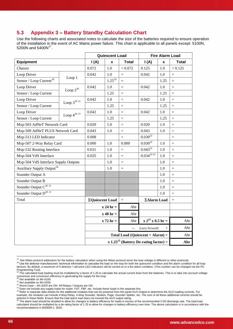
www.advancedco.com 66
5.3 Appendix 3 – Battery Standby Calculation Chart Use the following charts and associated notes to calculate the size of the batteries required to ensure operation of the installation in the event of AC Mains power failure. This chart is applicable to all panels except: 5100N, 5200N and 5400N
17.
Quiescent Load Fire Alarm Load
Equipment I (A) x Total I (A) x Total
Chassis 0.072 1.0 = 0.072 0.125 1.0 = 0.125
Loop Driver Loop 1
0.042 1.0 = 0.042 1.0 =
Sensor / Loop Current18
1.2519
= 1.25 =
Loop Driver Loop 2
20
0.042 1.0 = 0.042 1.0 =
Sensor / Loop Current 1.25 = 1.25 =
Loop Driver Loop 3
20 21
0.042 1.0 = 0.042 1.0 =
Sensor / Loop Current 1.25 = 1.25 =
Loop Driver Loop 4
20 21
0.042 1.0 = 0.042 1.0 =
Sensor / Loop Current 1.25 = 1.25 =
Mxp-503 AdNeT Network Card 0.020 1.0 = 0.020 1.0 =
Mxp-509 AdNeT PLUS Network Card 0.043 1.0 = 0.043 1.0 =
Mxp-513 LED Indicator 0.008 = 0.03022
=
Mxp-507 2-Way Relay Card 0.000 1.0 0.000 0.03022
1.0 =
Mxp-532 Routing Interface 0.031 1.0 = 0.04322
1.0 =
Mxp-504 VdS Interface 0.025 1.0 = 0.03422 23
1.0 =
Mxp-504 VdS Interface Supply Outputs 1.0 = 1.0 =
Auxiliary Supply Output24
1.0 = 1.0 =
Sounder Output A 1.0 =
Sounder Output B 1.0 =
Sounder Output C20
21
1.0 =
Sounder Output D20
21
1.0 =
Total Quiescent Load = Alarm Load =
x 24 hr = Ahr
x 48 hr = Ahr
x 72 hr = Ahr x 225
x 0.5 hr = Ahr
(carry forward) + Ahr
Total Load (Quiescent + Alarm) = Ahr
x 1.2525
(Battery De-rating factor) = Ahr
17
See Nittan protocol addendum for the battery calculation when using the Nittan protocol since the loop voltage is different to other protocols. 18
Use the detector manufacturers’ technical information to calculate the load on the loop for both the quiescent condition and fire alarm condition for all loop devices. By default, a maximum of 5 detector / call point LED indicators will be turned on in a fire alarm condition. (This number can be changed via the PC Programming Tool). 19
The calculated loop loading must be multiplied by a factor of 1.25 to calculate the actual current draw from the batteries. This is to take into account voltage conversion and conversion efficiency in generating the supply for the loop. 20
Not available on Mx-5100. 21
Not available on Mx-5200. 22
Worst Case – All LEDS are ON. All Relays / Outputs are ON. 23
Does not include any supply loads for router, FAT, FBF, etc. Include these loads in the separate line. 24
Refer to separate data sheets for the additional modules that can be powered from the panel AUX Output to determine the AUX loading currents. For example, the modules can include 4-Way Relay, 4-Way Sounder, Modem, Page, Sounder Splitter, etc. The sum of all these additional currents should be entered in these fields. Ensure that the total alarm load does not exceed the AUX output rating. 25
The alarm load should be doubled to allow for changes in battery efficiency for loads in excess of the recommended C/20 discharge rate. The total load calculated should be multiplied by a de-rating factor of 1.25 to allow for changes in battery efficiency over time. The above calculation is in accordance with the recommendations in BS5839-1: 2002.
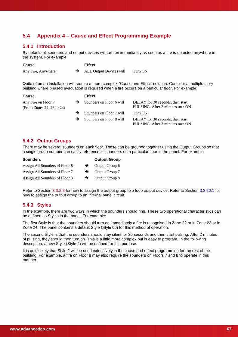
www.advancedco.com
67
5.4 Appendix 4 – Cause and Effect Programming Example
5.4.1 Introduction
By default, all sounders and output devices will turn on immediately as soon as a fire is detected anywhere in the system. For example:
Cause Effect
Any Fire, Anywhere. ALL Output Devices will Turn ON
Quite often an installation will require a more complex “Cause and Effect” solution. Consider a multiple story building where phased evacuation is required when a fire occurs on a particular floor. For example:
Cause Effect
Any Fire on Floor 7
(From Zones 22, 23 or 24)
Sounders on Floor 6 will DELAY for 30 seconds, then start
PULSING. After 2 minutes turn ON
Sounders on Floor 7 will Turn ON
Sounders on Floor 8 will DELAY for 30 seconds, then start
PULSING. After 2 minutes turn ON
5.4.2 Output Groups
There may be several sounders on each floor. These can be grouped together using the Output Groups so that a single group number can easily reference all sounders on a particular floor in the panel. For example:
Sounders Output Group
Assign All Sounders of Floor 6 Output Group 6
Assign All Sounders of Floor 7 Output Group 7
Assign All Sounders of Floor 8 Output Group 8
Refer to Section 3.3.2.8 for how to assign the output group to a loop output device. Refer to Section 3.3.20.1 for how to assign the output group to an internal panel circuit.
5.4.3 Styles
In the example, there are two ways in which the sounders should ring. These two operational characteristics can be defined as Styles in the panel. For example:
The first Style is that the sounders should turn on immediately a fire is recognised in Zone 22 or in Zone 23 or in Zone 24. The panel contains a default Style (Style 00) for this method of operation.
The second Style is that the sounders should stay silent for 30 seconds and then start pulsing. After 2 minutes of pulsing, they should then turn on. This is a little more complex but is easy to program. In the following description, a new Style (Style 2) will be defined for this purpose.
It is quite likely that Style 2 will be used extensively in the cause and effect programming for the rest of the building. For example, a fire on Floor 8 may also require the sounders on Floors 7 and 8 to operate in this manner.
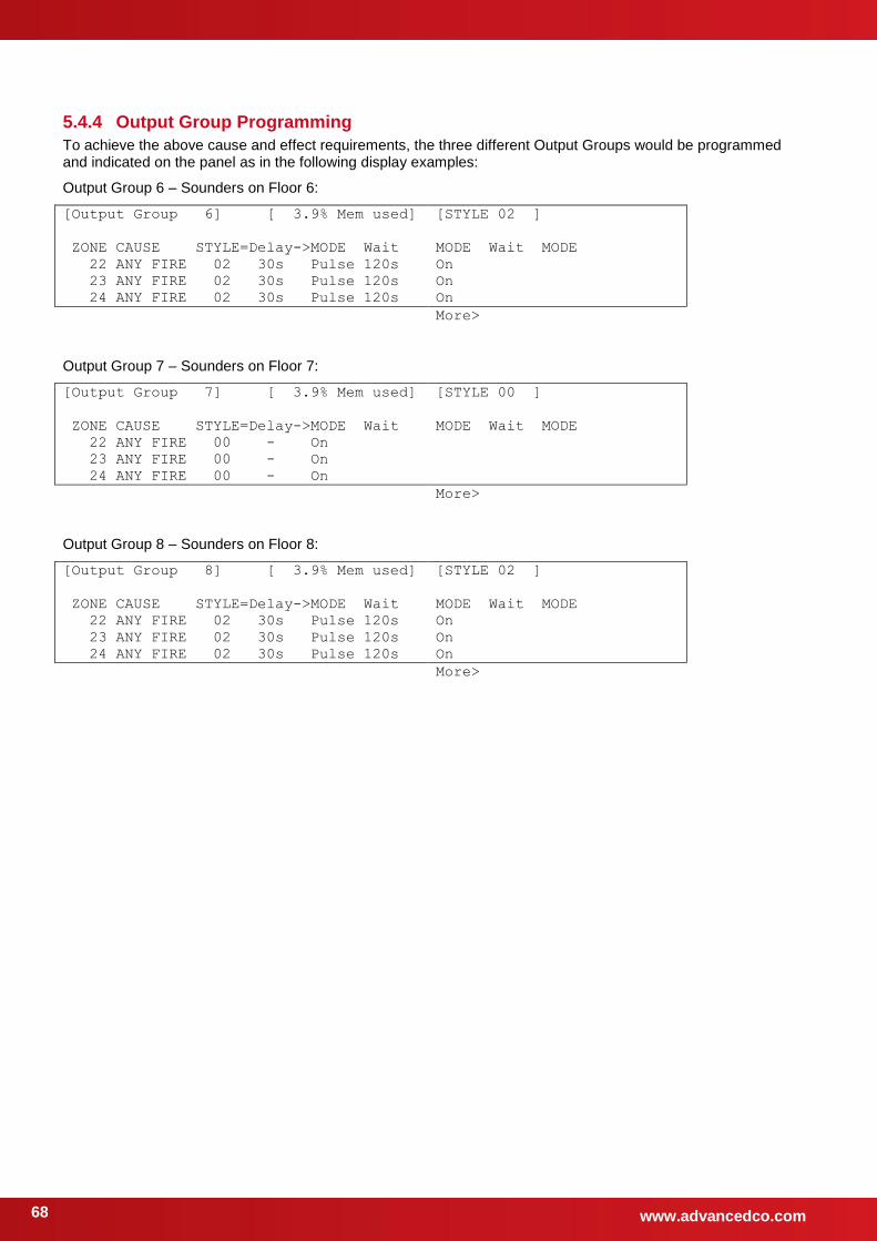
www.advancedco.com 68
5.4.4 Output Group Programming
To achieve the above cause and effect requirements, the three different Output Groups would be programmed and indicated on the panel as in the following display examples:
Output Group 6 – Sounders on Floor 6:
[Output Group 6] [ 3.9% Mem used]
ZONE CAUSE STYLE=Delay->MODE Wait
22 ANY FIRE 02 30s Pulse 120s
23 ANY FIRE 02 30s Pulse 120s
24 ANY FIRE 02 30s Pulse 120s
[STYLE 02 ]
MODE Wait MODE
On
On
On
More>
Output Group 7 – Sounders on Floor 7:
[Output Group 7] [ 3.9% Mem used]
ZONE CAUSE STYLE=Delay->MODE Wait
22 ANY FIRE 00 - On
23 ANY FIRE 00 - On
24 ANY FIRE 00 - On
[STYLE 00 ]
MODE Wait MODE
More>
Output Group 8 – Sounders on Floor 8:
[Output Group 8] [ 3.9% Mem used]
ZONE CAUSE STYLE=Delay->MODE Wait
22 ANY FIRE 02 30s Pulse 120s
23 ANY FIRE 02 30s Pulse 120s
24 ANY FIRE 02 30s Pulse 120s
[STYLE 02 ]
MODE Wait MODE
On
On
On
More>

www.advancedco.com
69
5.5 Appendix 5 – Other Useful Documents The following reference and application documents may be useful in the design, configuration and installation of the system.
The latest versions of these and new / additional application notes are available from the Advanced web site (www.advancedco.com) or in hard copy format from Sales.
Document Number
Title Type Description
680-156 Configuration Tool Software Level 3 Tool Explains how to configure the panel using the PC-NET-003 V6 PC Software.
680-023 Logo Software Level 4 Tool Explains how to create and update the logo in the panel using the PC-NET-007 PC software.
680-025 Key Switch Access Control Application Note Explains how to configure the panel for use of a key switch for level 2 access.
680-030 Flash Programming Level 4 Tool Explains how to update the panel firmware with new software revisions.
680-034 External Printer Output Application Note Explains how to configure the panel and connect a serial RS232 printer.
680-039 Class Change Programming Application Note Provides examples of how to implement a class change function using different inputs.
680-042 Gated Time-Clock Programming
Application Note Explains how to use an input to enable / disable a time-click function.
680-058 Hochiki Sounders and Outputs Application Note Explains how to configure the panel for operation with the ranges of sounders and output devices. Also details limitations.
680-059 Apollo Ancillary Base Sounders Application Note Explains how to configure the panel for operation with detector LED driven base sounders. Also details limitations.
680-085 Software Upgrades Application Note Explains how to upgrade the software in the Graphics Display Card and Fault Tolerant Network Card. Refer to 680-030 for general panel software flash programming information and guidance.
680-088 Cables for Fire Systems Application Note Gives further information on the cables than can be used.
680-116 Minimizing False Alarms Application Note Details the diverse methods that can be configured to assist in the reduction of false alarms.
680-167 Apollo Device Information Application Note Compatibility List and technical information
680-168 Hochiki Device Information Application Note Compatibility List and technical information
680-169 AV Device Information Application Note Compatibility List and technical information
680-170 Nittan Device Information Application Note Compatibility List and technical information
680-501 Mx-5000 Fire Routing / Protection
Application Note Detailed information on how to configure and program fire routing and fire protection outputs
680-502 Mx-5000 Network Application Note Explains how to install and configure the
and networks.
680-503 Mx-5000 Bezels Application Note Details of how to fit semi-flushing bezels
680-504 Mx-5000 IFAM Configuration Application Note Detailed installation and configuration information for the IFAM FAT and FBF panels
680-505 Mx-5000 Scope Function Application Note Details of how to use the oscilloscope function
680-506 Mx-5000 Glass Door Kits Application Note Details of how to fit glass door kits
680-507 Mx-5000 Key Switches Application Note Details on key switch options
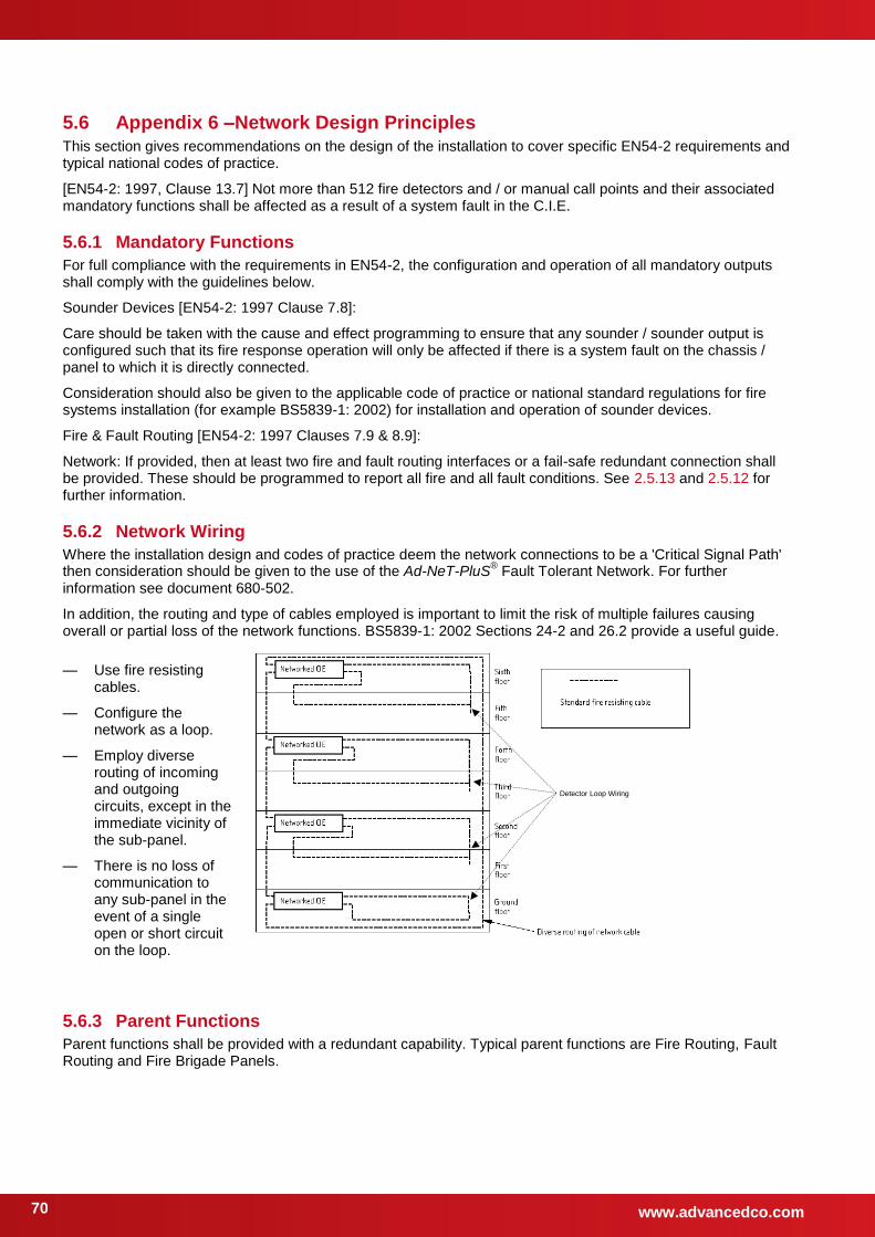
www.advancedco.com 70
5.6 Appendix 6 –Network Design Principles This section gives recommendations on the design of the installation to cover specific EN54-2 requirements and typical national codes of practice.
[EN54-2: 1997, Clause 13.7] Not more than 512 fire detectors and / or manual call points and their associated mandatory functions shall be affected as a result of a system fault in the C.I.E.
5.6.1 Mandatory Functions
For full compliance with the requirements in EN54-2, the configuration and operation of all mandatory outputs shall comply with the guidelines below.
Sounder Devices [EN54-2: 1997 Clause 7.8]:
Care should be taken with the cause and effect programming to ensure that any sounder / sounder output is configured such that its fire response operation will only be affected if there is a system fault on the chassis / panel to which it is directly connected.
Consideration should also be given to the applicable code of practice or national standard regulations for fire systems installation (for example BS5839-1: 2002) for installation and operation of sounder devices.
Fire & Fault Routing [EN54-2: 1997 Clauses 7.9 & 8.9]:
Network: If provided, then at least two fire and fault routing interfaces or a fail-safe redundant connection shall be provided. These should be programmed to report all fire and all fault conditions. See 2.5.13 and 2.5.12 for further information.
5.6.2 Network Wiring
Where the installation design and codes of practice deem the network connections to be a 'Critical Signal Path' then consideration should be given to the use of the Ad-NeT-PluS
® Fault Tolerant Network. For further
information see document 680-502.
In addition, the routing and type of cables employed is important to limit the risk of multiple failures causing overall or partial loss of the network functions. BS5839-1: 2002 Sections 24-2 and 26.2 provide a useful guide.
— Use fire resisting cables.
— Configure the network as a loop.
— Employ diverse routing of incoming and outgoing circuits, except in the immediate vicinity of the sub-panel.
— There is no loss of communication to any sub-panel in the event of a single open or short circuit on the loop.
Detector Loop Wiring
5.6.3 Parent Functions
Parent functions shall be provided with a redundant capability. Typical parent functions are Fire Routing, Fault Routing and Fire Brigade Panels.
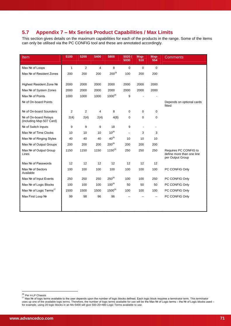
www.advancedco.com
71
5.7 Appendix 7 – Mx Series Product Capabilities / Max Limits This section gives details on the maximum capabilities for each of the products in the range. Some of the items can only be utilised via the PC CONFIG tool and these are annotated accordingly.
Item 5100 5200 5400 5800 5020 / 5030
Mxp-510
Mxp-554
Comments
Max of Loops 1 2 4 8 0 0 0
Max of Resident Zones 200 200 200 20026
100 200 200
Highest Resident Zone 2000 2000 2000 2000 2000 2000 2000
Max of System Zones 2000 2000 2000 2000 2000 2000 2000
Max of Points 1000 1000 1000 100026
9 - -
of On-board Points Depends on optional cards fitted
of On-board Sounders 2 2 4 8 0 0 0
of On-board Relays (including Mxp-507 Card)
2(4) 2(4) 2(4) 4(8) 0 0 0
of Switch Inputs 9 9 9 18 9 - -
Max of Time Clocks 10 10 10 1026
-- 3 3
Max of Ringing Styles 40 40 40 4026
10 10 10
Max of Output Groups 200 200 200 20026
200 200 200
Max of Output Group Lines
1150 1150 1150 115026
250 250 250 Requires PC CONFIG to define more than one line per Output Group
Max of Passwords 12 12 12 12 12 12 12
Max of Sectors Available
100 100 100 100 100 100 100 PC CONFIG Only
Max of Input Events 250 250 250 25026
100 100 250 PC CONFIG Only
Max of Logic Blocks 100 100 100 10026
50 50 50 PC CONFIG Only
Max of Logic Terms27
1500 1500 1500 150026
100 100 100 PC CONFIG Only
Max First Loop 99 98 96 96 -- -- -- PC CONFIG Only
26
Per 4-LP Chassis 27
Max of logic terms available to the user depends upon the number of logic blocks defined. Each logic block requires a terminator term. This terminator uses up one of the available logic terms. Therefore, the number of logic terms available for use will be the Max of Logic terms – the of Logic blocks used – for example, using 20 logic blocks in an Mx-5400 will give 500-20=480 Logic Terms available to use.

www.advancedco.com 72
This page is intentionally left blank.

www.advancedco.com
73
USER NOTES

www.advancedco.com 74
Advanced Electronics Ltd
Moorland Way, Cramlington, Northumberland, NE23 1WE UK
Tel: +44 (0)1670 707 111 Fax: +44 (0)1670 707 222
Email: [email protected] Web: www.advancedco.com
Doc Number: 680-165
Revision: 05
First Issued: 2010-10-19