
FIO-31 Digital I/O Extension Quick Guide - ABB Group · FIO-31 Digital I/O Extension ... sempre...
13
ABB Drives Quick Guide FIO-31 Digital I/O Extension English. . . . . . . . . . . . . . . . . . . . . 2 Deutsch . . . . . . . . . . . . . . . . . . . . 6 Italiano . . . . . . . . . . . . . . . . . . . . 10 3AUA0000055163 Rev B Effective: 18.11.2009 © 2009 ABB Oy. All rights reserved.
Transcript of FIO-31 Digital I/O Extension Quick Guide - ABB Group · FIO-31 Digital I/O Extension ... sempre...

ABB Drives
Quick GuideFIO-31 Digital I/O Extension
English. . . . . . . . . . . . . . . . . . . . . 2Deutsch . . . . . . . . . . . . . . . . . . . . 6Italiano. . . . . . . . . . . . . . . . . . . . 10
3AUA0000055163 Rev BEffective: 18.11.2009
© 2009 ABB Oy. All rights reserved.

2
Quick guide - FIO-31
IntroductionThis manual contains the very basic information about installing the FIO-31 Digital I/O Extension. For complete documentation see FIO-31 Digital I/O Extension User’s Manual[3AUA0000055162 (English)]. To find the manual, go tohttp://www.abb.com/ and search with the code 3AUA0000055162.
Safety instructions
WARNING! All electrical installation and maintenance work on the drive should be carried out by qualified electricians only.
The drive and adjoining equipment must be properly earthed.
Do not attempt any work on a powered drive. After switching off the mains, always allow the intermediate circuit capacitors to discharge for 5 minutes before working on the frequency converter, the motor or the motor cable. It is good practice to check (with a voltage indicating instrument) that the drive is in fact discharged before beginning work.
These warnings are intended for all who work on the drive. Ignoring the instructions can cause physical injury or death, or damage the equipment.
For complete safety instructions see the drive manuals.
Quick guide - FIO-31

3
Mounting
WARNING! Before installation, switch off the drive power supply. Wait for five minutes to ensure that the capacitor bank of the drive is discharged. Switch off all dangerous voltages connected from external control circuits to the inputs and outputs of the drive.
• Insert the module carefully into the option slot of the drive until the retaining clips lock the module into position.
• Fasten the screw (included) to the stand-off.
Note: Correct installation of the screw is essential for fulfilling the EMC requirements and for proper operation of the module.
Installation sites above 2000 metres (6562 feet)The Protective Extra Low Voltage (PELV) requirements are not fulfilled when altitude is greater than 2000 m (6562 feet) and relays are used with voltage greater than 48 V.
Quick guide - FIO-31
4
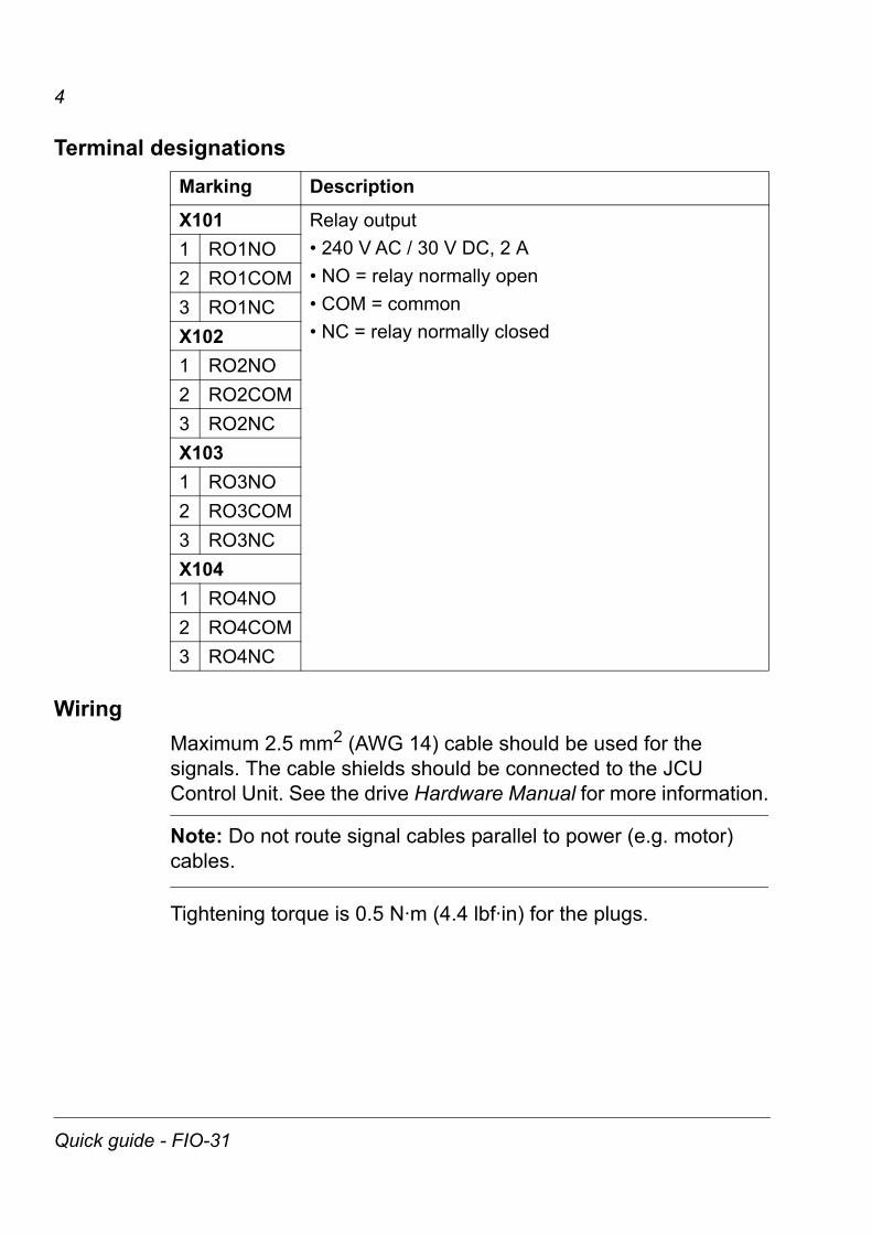
Terminal designations
WiringMaximum 2.5 mm2 (AWG 14) cable should be used for the signals. The cable shields should be connected to the JCU Control Unit. See the drive Hardware Manual for more information.
Note: Do not route signal cables parallel to power (e.g. motor) cables.
Tightening torque is 0.5 N·m (4.4 lbf·in) for the plugs.
Marking Description
X101 Relay output• 240 V AC / 30 V DC, 2 A• NO = relay normally open• COM = common• NC = relay normally closed
1 RO1NO2 RO1COM3 RO1NCX1021 RO2NO2 RO2COM3 RO2NCX1031 RO3NO2 RO3COM3 RO3NCX1041 RO4NO2 RO4COM3 RO4NC
Quick guide - FIO-31

5
ProgrammingThe communication between the module and the drive is activated by a drive parameter. See the drive Firmware Manual.
CHASSIS
63 mm
2.48 in
106
mm
4.17
in
1 Diagnostic LED
2 Fixing screw
3 Relay outputs
1
2
3 3
Quick guide - FIO-31

6
Kurzanleitung - FIO-31
EinleitungDieses Handbuch enthält grundlegende Informationen für die Installation des Digital-E/A-Erweiterungsmoduls FIO-31. Die vollständige Dokumentation finden Sie im FIO-01 Digital-E/A-Erweiterungsmodul Benutzerhandbuch[3AUA0000055162 (Englisch)]. Sie finden das Handbuch, wenn Sie auf http://www.abb.com/ navigieren und den Code 3AUA0000055162 eingeben.
Sicherheitsvorschriften
WARNUNG! Alle elektrischen Installations- und Wartungsarbeiten an dem Frequenzumrichter dürfen nur von qualifiziertem Fachper-sonal durchgeführt werden.
Der Antrieb und die benachbarten Geräte sind fachgerecht zu erden.
Auf keinen Fall dürfen Arbeiten an einem eingeschalteten Antrieb durchgeführt werden. Warten Sie nach dem Abschalten der Spannungsversorgung stets fünf Minuten, bis die Zwischenkreis-kondensatoren entladen sind, bevor Sie mit der Arbeit an Frequenzumrichter, Motor oder Motorkabel beginnen. Vor Beginn der Arbeiten ist mit einem Spannungsprüfer zu prüfen, ob der Antrieb tatsächlich spannungsfrei ist.
Diese Warnungen gelten für alle Personen, die an dem Frequenz-umrichter arbeiten. Das Nichtbefolgen dieser Anweisungen kann zu Verletzungen, zum Tod oder auch zu Schäden an der Einrich-tung führen.
Die vollständigen Sicherheitsvorschriften finden Sie in den Hand-büchern der Frequenzumrichter.
Kurzanleitung - FIO-31

7
Montage
WARNUNG! Schalten Sie vor der Installation die Spannungsver-sorgung ab. Warten Sie fünf Minuten, um sicherzustellen, dass die Kondensatoren des Frequenzumrichters entladen sind. Schalten Sie alle gefährlichen Spannungen ab, die von externen Stromkrei-sen an den Ein- und Ausgängen des Antriebs anliegen können.
• Das Modul vorsichtig so weit in den Optionssteckplatz des Fre-quenzumrichters einsetzen, bis die Halteklammern einrasten.
• Befestigen Sie das Modul mit der Schraube (mitgeliefert).
Hinweis: Die ordnungsgemäße Befestigung der Schraube ist für die Einhaltung der EMV-Vorschriften und für einen störungsfreien Betrieb des Moduls wichtig.
Installationsorte oberhalb von 2000 Metern (6562 Fuß) ü.N.N.Die Anforderungen der Protective Extra Low Voltage (PELV) wer-den bei Installationen oberhalb von 2000 m (6562 Fuß) ü.N.N. und Relais mit einer höheren Spannung als 48 V nicht erfüllt.
Kurzanleitung - FIO-31

8
Anschlussbezeichnungen
VerdrahtungFür die Signale dürfen nur Kabel mit einem maximalen Quer-schnitt von 2,5 mm2 (AWG 14) verwendet werden. Die Kabel-schirme sollten an die Regelungseinheit JCU angeschlossen werden. Weitere Informationen enthält das Hardware-Handbuch des Frequenzumrichters.
Hinweis: Die Signalkabel dürfen nicht parallel zu Leistungskabeln (z.B. Motorkabeln) verlegt werden.
Das Anzugsmoment der Anschlüsse beträgt 0,5 Nm (4,4 lb·in).
Kennzeichnung Beschreibung
X101 Relaisausgang• 240 V AC / 30 V DC, 2 A• NO = Relais-Typ „Schließer“• COM = Masse• NC = Relais-Typ „Öffner“
1 RO1NO2 RO1COM3 RO1NCX1021 RO2NO2 RO2COM3 RO2NCX1031 RO3NO2 RO3COM3 RO3NCX1041 RO4NO2 RO4COM3 RO4NC
Kurzanleitung - FIO-31
9
ProgrammierungDie Kommunikation zwischen dem Modul und dem Frequenzum-richter wird über einen Antriebsparameter aktiviert. Siehe Firm-ware-Handbuch des Frequenzumrichters.
CHASSIS
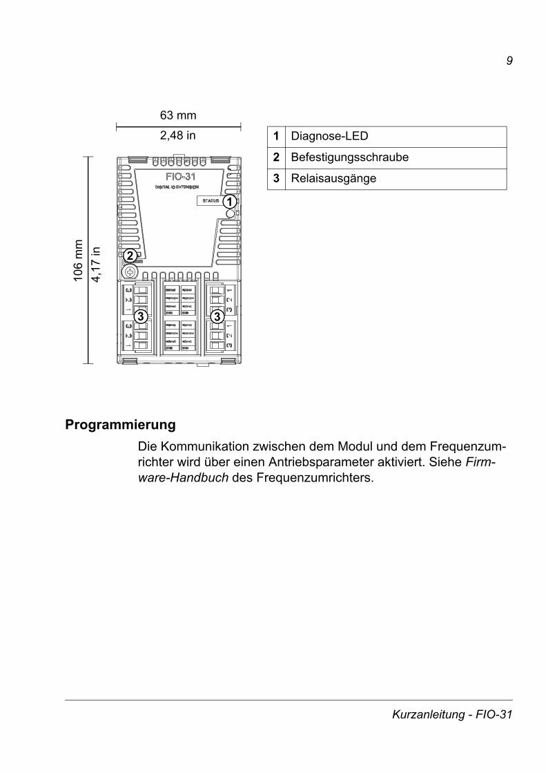
63 mm
2,48 in
106
mm
4,17
in
1 Diagnose-LED
2 Befestigungsschraube
3 Relaisausgänge
1
2
3 3
Kurzanleitung - FIO-31

10
Guida rapida - FIO-31
IntroduzioneIl presente manuale contiene le informazioni base per l’installazione dell’estensione degli I/O digitali FIO-31. Per la documentazione completa, vedere FIO-31 Digital I/O Extension User’s Manual [3AUA0000055162 (inglese)]. Per consultare il manuale, visitare il sito http://www.abb.com/ e cercare il codice 3AUA0000055162.
Norme di sicurezza
AVVERTENZA! L'installazione elettrica e gli interventi di manutenzione sul convertitore di frequenza devono essere eseguiti solo da elettricisti qualificati.
Il convertitore di frequenza e le apparecchiature collegate devono essere adeguatamente messi a terra.
Non effettuare alcun intervento su un convertitore sotto tensione. Dopo aver scollegato l’alimentazione, prima di intervenire sul convertitore di frequenza, sul motore o sul cavo motore, attendere sempre cinque minuti per consentire la scarica dei condensatori del circuito intermedio. È buona norma, prima di intervenire, verificare (con un misuratore di tensione) che il convertitore di frequenza sia effettivamente scarico.
Queste avvertenze sono rivolte a tutto il personale che effettua interventi sul convertitore di frequenza. Il mancato rispetto delle norme può mettere a repentaglio l’incolumità fisica, con rischio di morte, o danneggiare le apparecchiature.
Per le norme di sicurezza complete, consultare i manuali del convertitore di frequenza.
Guida rapida - FIO-31

11
Montaggio
AVVERTENZA!Prima dell’installazione, scollegare l’alimentazione del convertitore di frequenza. Attendere cinque minuti per essere certi che il banco di condensatori del convertitore sia scarico. Disinserire tutte le tensioni pericolose collegate mediante circuiti di controllo esterni agli ingressi e alle uscite del convertitore.
• Inserire delicatamente il modulo nello slot opzionale del convertitore finché le clip non lo bloccano in posizione.
• Serrare la vite (inclusa) al distanziale.
Nota: è essenziale installare in modo corretto la vite per ottemperare ai requisiti EMC e per il corretto funzionamento del modulo.
Luoghi di installazione ad altitudini superiori a 2000 m (6562 ft)I requisiti di protezione da minima tensione (PELV, Protective Extra Low Voltage) non sono soddisfatti ad altitudini superiori a 2000 m (6562 ft) e quando i relè sono utilizzati con tensione superiore a 48 V.
Guida rapida - FIO-31
12
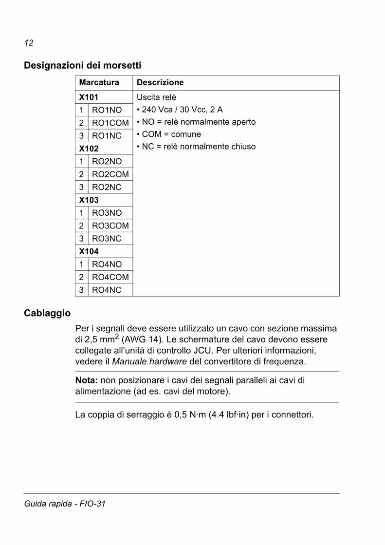
Designazioni dei morsetti
CablaggioPer i segnali deve essere utilizzato un cavo con sezione massima di 2,5 mm2 (AWG 14). Le schermature del cavo devono essere collegate all’unità di controllo JCU. Per ulteriori informazioni, vedere il Manuale hardware del convertitore di frequenza.
Nota: non posizionare i cavi dei segnali paralleli ai cavi di alimentazione (ad es. cavi del motore).
La coppia di serraggio è 0,5 N·m (4.4 lbf·in) per i connettori.
Marcatura Descrizione
X101 Uscita relè• 240 Vca / 30 Vcc, 2 A• NO = relè normalmente aperto• COM = comune• NC = relè normalmente chiuso
1 RO1NO2 RO1COM3 RO1NCX1021 RO2NO2 RO2COM3 RO2NCX1031 RO3NO2 RO3COM3 RO3NCX1041 RO4NO2 RO4COM3 RO4NC
Guida rapida - FIO-31

13
ProgrammazioneLa comunicazione tra il modulo e il convertitore si attiva con un parametro del convertitore. Vedere il Manuale firmware del convertitore.
CHASSIS
63 mm
2,48 in
106
mm
4,17
in
1 LED di diagnostica
2 Vite di fissaggio
3 Uscite relè
1
2
3 3
Guida rapida - FIO-31