Finite Element Analysis of Funicular Shells with ... · Finite Element Analysis of Funicular Shells...
6
International Research Journal of Engineering and Technology (IRJET) e-ISSN: 2395 -0056 Volume: 03 Issue: 09 | Sep-2016 www.irjet.net p-ISSN: 2395-0072 © 2016, IRJET | Impact Factor value: 4.45 | ISO 9001:2008 Certified Journal | Page 873 Finite Element Analysis of Funicular Shells with Rectangular plan ratio 1:0.7 under Concentrated Load using SAP2000 Siddesh T M 1 , Harish B A 2 , Dr. K Manjunatha 3 1 PG Student, Department of Civil Engineering, UBDTCE, Davanagere-577004, Karnataka, India 2 Assistant Professor, Department of Civil Engineering, GMIT, Davanagere-577006, Karnataka, India 3 Professor and chairman, Department of Civil Engineering, UBDTCE, Davanagere-577004, Karnataka, India ---------------------------------------------------------------------***--------------------------------------------------------------------- Abstract - A shell structure is a three dimensional structure, thin in one direction and long in the other two directions. Such structures are abundantly found in nature, although thin and light, they span over relatively large areas, and hold applied loads in a very effective way. It seems that with shell structures, nature have maximized the ability to span over large areas with a minimum amount of material. The shell of an egg is an impressive example. Also, of course, shell structures in nature can be very beautiful and have indeed inspired many artists. All buildings are meant to enclose spaces. Most of the different types of superstructures we commonly used for present day building are only a modification of the age old system of column, beam and roof covering arrangements. They fulfill their function by two separate systems. One is the space covering system to cover the space, such as concrete slab or roof covering sheets in steel building. These are supported by a second system of beams and columns which we may call the supporting system. In many steel buildings they are obviously separate and in R.C buildings also, they are treated as two separate systems. In reinforced concrete shells, however, the two functions of covering the space and supporting the covering system are integrated into one. The structure covers the space without beams and columns within the buildings. In this study doubly curved thin shells are analyzed using Finite Element software SAP 2000 with new version. Doubly curved shells which are in rectangular plan having 1mX0.7m are considered. The behavior of shells under concentrated load varying from 1to5KN is studied and compared with the slabs of same dimension and thickness .In this case study deflection curves, membrane stress and stress contour diagram are obtained. It is observed that with the increase in rise and thickness of funicular shell the deflection are reduced. The membrane stresses decreases with the increase in rise and thickness of concrete funicular shell. Key Words: Edge beam, Funicular shell, Rise, Thickness, Stress contour, Deflection. 1. INTRODUCTION The shells of double curvature are stronger when compared to shells of single curvature, equivalent to cylindrical shells. Further, the arch distributes the load in all paths equally and resists the impact of loading at any point. These shells are used as floors and also as roofs. Funicular shells are a class of doubly curved shells, the form of which satisfies the desired state of stress in its body for the given loading and boundary conditions. The state of stress favored in an unreinforced concrete thin shell will be pure compression unaccompanied by shear and bending stresses. Under different conditions of loading, bending moments would strengthen and the shell will not behave only as a funicular element. Analytically, it's possible to compute the funicular surface of any ground plan for the given loading conditions. The shapes of these shells are choosen that, under uniformly distributed vertical loads, in a membrane state of stress, they develop only pure compression unaccompanied by shear stresses. Thus theoretically no reinforcement will be necessary except in the edge members. Small precast funicular shells without any reinforcement except in edge beams are suitable for roofs and floors of residential, industrial, and institutional buildings. For roofs of larger size in situ construction may be resorted, in such shells provision of reinforcement is necessary to take care of the effects of shrinkage, temperature and bending. In the lower portion steel reinforcements are required to counter the tensile stresses. It can be converted as compression structure by inverting it, with a considerable reduction in the quantity of steel & cement. Compression structures are used in the form of vaults, arches, catenaries, domes and doubly curved shells also known as funicular shells have been used extensively in the construction of forts and temples. These structures are the best proof for the durable performance of shell structures. The funicular shell roof structure is one such compression structure, which can be built by utilizing waste materials and natural resources can be conserved effectively and use of expensive steel and cement are optimized. Further, point load is distributed equally in all direction by arch thus it is able to withstand the impact of loading at any point. Diagonal grid of funicular shell gives the illusion of a larger space. A typical view of funicular shells used for a roof construction is shown in figure 1.
Transcript of Finite Element Analysis of Funicular Shells with ... · Finite Element Analysis of Funicular Shells...

International Research Journal of Engineering and Technology (IRJET) e-ISSN: 2395 -0056
Volume: 03 Issue: 09 | Sep-2016 www.irjet.net p-ISSN: 2395-0072
© 2016, IRJET | Impact Factor value: 4.45 | ISO 9001:2008 Certified Journal | Page 873
Finite Element Analysis of Funicular Shells with Rectangular plan ratio
1:0.7 under Concentrated Load using SAP2000
Siddesh T M1, Harish B A2, Dr. K Manjunatha3
1PG Student, Department of Civil Engineering, UBDTCE, Davanagere-577004, Karnataka, India 2Assistant Professor, Department of Civil Engineering, GMIT, Davanagere-577006, Karnataka, India
3Professor and chairman, Department of Civil Engineering, UBDTCE, Davanagere-577004, Karnataka, India
---------------------------------------------------------------------***---------------------------------------------------------------------
Abstract - A shell structure is a three dimensional structure, thin in one direction and long in the other two directions. Such structures are abundantly found in nature, although thin and light, they span over relatively large areas, and hold applied loads in a very effective way. It seems that with shell structures, nature have maximized the ability to span over large areas with a minimum amount of material. The shell of an egg is an impressive example. Also, of course, shell structures in nature can be very beautiful and have indeed inspired many artists. All buildings are meant to enclose spaces. Most of the different types of superstructures we commonly used for present day building are only a modification of the age old system of column, beam and roof covering arrangements. They fulfill their function by two separate systems. One is the space covering system to cover the space, such as concrete slab or roof covering sheets in steel building. These are supported by a second system of beams and columns which we may call the supporting system. In many steel buildings they are obviously separate and in R.C buildings also, they are treated as two separate systems. In reinforced concrete shells, however, the two functions of covering the space and supporting the covering system are integrated into one. The structure covers the space without beams and columns within the buildings. In this study doubly
curved thin shells are analyzed using Finite Element software SAP 2000 with new version. Doubly curved shells which are in rectangular plan having 1mX0.7m are considered. The behavior of shells under concentrated load varying from 1to5KN is studied and compared with the slabs of same dimension and thickness .In this case study deflection curves, membrane stress and stress contour diagram are obtained. It is observed that with the increase in rise and thickness of funicular shell the deflection are reduced. The membrane stresses decreases with the increase in rise and thickness of concrete funicular shell. Key Words: Edge beam, Funicular shell, Rise, Thickness,
Stress contour, Deflection.
1. INTRODUCTION
The shells of double curvature are stronger when compared to shells of single curvature, equivalent to cylindrical shells. Further, the arch distributes the load in all paths equally and resists the impact of loading at any point.
These shells are used as floors and also as roofs. Funicular shells are a class of doubly curved shells, the form of which satisfies the desired state of stress in its body for the given loading and boundary conditions. The state of stress favored in an unreinforced concrete thin shell will be pure compression unaccompanied by shear and bending stresses. Under different conditions of loading, bending moments would strengthen and the shell will not behave only as a funicular element. Analytically, it's possible to compute the funicular surface of any ground plan for the given loading conditions.
The shapes of these shells are choosen that, under uniformly distributed vertical loads, in a membrane state of stress, they develop only pure compression unaccompanied by shear stresses. Thus theoretically no reinforcement will be necessary except in the edge members. Small precast funicular shells without any reinforcement except in edge beams are suitable for roofs and floors of residential, industrial, and institutional buildings. For roofs of larger size in situ construction may be resorted, in such shells provision of reinforcement is necessary to take care of the effects of shrinkage, temperature and bending.
In the lower portion steel reinforcements are required to counter the tensile stresses. It can be converted as compression structure by inverting it, with a considerable reduction in the quantity of steel & cement. Compression structures are used in the form of vaults, arches, catenaries, domes and doubly curved shells also known as funicular shells have been used extensively in the construction of forts and temples. These structures are the best proof for the durable performance of shell structures. The funicular shell roof structure is one such compression structure, which can be built by utilizing waste materials and natural resources can be conserved effectively and use of expensive steel and cement are optimized. Further, point load is distributed equally in all direction by arch thus it is able to withstand the impact of loading at any point. Diagonal grid of funicular shell gives the illusion of a larger space.
A typical view of funicular shells used for a roof construction is shown in figure 1.

International Research Journal of Engineering and Technology (IRJET) e-ISSN: 2395 -0056
Volume: 03 Issue: 09 | Sep-2016 www.irjet.net p-ISSN: 2395-0072
© 2016, IRJET | Impact Factor value: 4.45 | ISO 9001:2008 Certified Journal | Page 874
Fig-1: Typical view of Funicular Shell roof.
2. Literature review
Abolhassan vafai, Massoud mofid and Homayoon E.Estekanchi (1997) have done an experimental study on prefabricated funicular shells. Along diagonal of the sections experimental values and theoretical values of membrane stresses are compared. The results were similar to the theoretical results. Experimental results of vertical deflections along the transverse sections & longitudinal sections of the shells also favorable with the theory. Experimental failure and crack loads are found & empirical equations, expressing the relation between rise & failure crack loads, are given. Based on the design forty five models were constructed. First eight samples of them are loaded to a specified supported at four edges load within elastic region. Both inside and outside Electrical resistance gauges were mounted at several locations along the diagonal on the surface of the shell on two different specimens with rise of 6cm & 9cm, respectively. Also in other six specimens having different rise & type of reinforcement dial gauges are installed at several locations on the surface. Following these non-destructive tests all 45 samples subjected to concentrated load at centre and are loaded to failure. The finite element technique is used to analyze a similar model in the elastic range to relate experimental results to theory.
P.Sachithanantham, S.Elavenil and S.Sankaran (2011) explained about the funicular shells with square plan with different rises and analyzed for concentrated central force. Shell units of size 1m x 1m in plan with 0.04m X 0.04m edge beam are prepared by M20 grade cement concrete with mix design by IS method. For casting the shells a form made up of square steel frame and foam leather rexine is used. Specimens with different rises of 8cm, 12cm and 16cm are prepared and moist cured for 28 days. On the centre of the shell specimen a concentrated force is applied and within the elastic range corresponding deflections are observed. All the shell specimens are subjected to failure after the elastic range to obtain the ultimate loads. Finite element models of shell specimens are developed and by using Total station coordinates are determined. Using standard software
Analysis and computation of stresses are done. A relation between span to rise ratio and ultimate loads is arrived. By comparing the experimental and analytical results conclusions are made.
P.Sachithanantham (2012) has done the work on funicular shells having rectangular plan and various rises under concentrated central force on its apex. The Specimens of measurement 600mm x 1000mm in plan having edge beam of 40mm x 40mm are prepared by cement concrete of grade M30. The specimens consist of varying rises(R) of 0.052m, 0.069m, and 0.097m. Deflections are measured under the concentrated force on the center of the shell. Finite element models of the shell specimens are developed and the coordinates are decided using total station. Using standard software Analysis and computation of stresses are done for the modeled shells. A relation between span to rise ratio & ultimate loads is arrived.
Tongbram Tarunkumar and P.Sachithanantham (2012) Carried out work on the Concrete shallow funicular shells of rectangular plan, by considering the specimens with three various rises(R) of 3.15 in. [80 mm], 3.546 in. [90 mm], and 4.88 in. [124 mm]. The concentrated force is applied over the centre of the specimen and corresponding deflections are noted. Finite element models of the shell specimens are developed and the coordinates are decided using total station. Analysis and computation of stresses are carried for the modeled shells using standard software. A relation between span to rise ratio & ultimate loads is arrived. Conclusions are made by comparing the analytical results.
Dr. S. Sankaran, P. Sachithanantham, Dr. S. Elavenil (2014) described about the funicular shells which rectangular ground plan. Specimens of size a 1m x 0.9m in plan with 4cm X 4cm edge beam are ready with M30 grade concrete, specimens are made with different rises & moist cured. The deflections & strains of Specimens are noted under corresponding ultimate loads. With different rises failure patterns of shells are observed. From the experimental outcomes a relation between ultimate load and span to rise ratio is arrived & hence concluded that ultimate loads are functions of the rise of the shells.
P. Sachithanantham, S. Sankaran, S. Elavenil(2015) has done work funicular shells with rectangular ground plan of dimension 1m x 0.5m in plan with 0.04m X 0.04m edge beam with M30 grade concrete which is designed by IS method. With different rises specimens are prepared & moist cured. These specimens are subjected to ultimate loads & the corresponding deflections & strains are noted. Failure patterns of shells were observed with various rises. Using these experimental values a relation between ultimate load & span to rise ratio is arrived & hence concluded that the ultimate loads are functions of the rise of the shells.

International Research Journal of Engineering and Technology (IRJET) e-ISSN: 2395 -0056
Volume: 03 Issue: 09 | Sep-2016 www.irjet.net p-ISSN: 2395-0072
© 2016, IRJET | Impact Factor value: 4.45 | ISO 9001:2008 Certified Journal | Page 875
3. Objectives of the work Concrete funicular shells of rectangular in ground plan, with doubly curved surfaces and various rises and thickness are analyzed by using finite element method. To study the behavior of funicular shells under concentrated load and comparing with the slab of same dimension. In this work an analytical investigation on doubly curved funicular shell with ground plan ratio 1:0.7 subjected to concentrated load with distinct rise at L/10 and L/20 with thickness of 20mm, 40mm and 50mm is offered. The dimensions of the slabs and shells with their rise and thickness are shown in Table 1.
Table -1: Size of shells and slabs. SHELLS WITH VARYING RISES & THICKNESS
Geometry of the shells
Designation of the shell
Plan dimensions
in mm
Rise (R) in mm
Thickness in mm
Rectangle
FS I 1000x700 100 50 FS II 1000x700 100 40
FS III 1000x700 100 20
FS IV 1000x700 50 50 FS V 1000x700 50 40
FSV VI 1000x700 50 20
SLABS WITH VARYING THICKNESS
Geometry of the slab
Designation of the slab
Plan dimensions
in mm
Thickness in mm
Rise (R) in mm
Rectangle
SLAB I 1000x700 50 0
SLAB II 1000x700 40 0 SLAB III 1000x700 20 0
4. Finite Element Modeling and Analysis The shells were modeled with dimensions as mentioned in
“Table 1”,the rise of shell is taken at L/10 and L/20 where L
is the span 1000mm and the edge beam thickness is taken as
two to three times the thickness of shell, and all models are
fixed supported at the edges. For material properties, M20
grade concrete properties are considered. The models were
discritized and subjected concentrated load varying from 1-
5kN .The 3D model of FS I is shown in Figure2, discritized
model is shown in Figure3 and model after applying load is
shown in Figure 4.
Fig -2: 3D model of shell FS I
Fig-3: Discritized model of shell FS I
Fig-4: FS I Shell model after loading
After applying load the corresponding deflections
and stresses at nodes were noted and graph is plotted with corresponding load and distance. The stress contour and deflected model is shown in Figure 5 and Figure 6 respectively and the graph of stress and deflection values for shell FS I is shown in Chart 1 and Chart 2 respectively. Similarly analysis is carried out for every shell and the values are obtained.
Fig-5: Stress contour of shell FS I
International Research Journal of Engineering and Technology (IRJET) e-ISSN: 2395 -0056
Volume: 03 Issue: 09 | Sep-2016 www.irjet.net p-ISSN: 2395-0072
© 2016, IRJET | Impact Factor value: 4.45 | ISO 9001:2008 Certified Journal | Page 876
Fig-6: Deflected shape of shell FS I
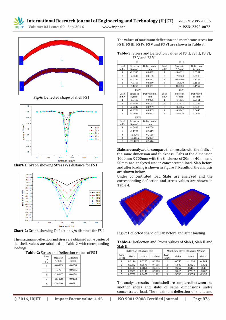
Chart-1: Graph showing Stress v/s distance for FS I
Chart-2: Graph showing Deflection v/s distance for FS I
The maximum deflection and stress are obtained at the center of
the shell, values are tabulated in Table 2 with corresponding
loadings.
Table-2: Stress and Deflection values of FS I Load
in kN
Stress in N/mm2
Deflection in mm
1 -0.6815 0.0058
2 -1.3704 0.0116
3 -2.0447 0.0174
4 -2.7408 0.0232
5 -3.4260 0.0291
The values of maximum deflection and membrane stress for FS II, FS III, FS IV, FS V and FS VI are shown in Table 3. Table-3: Stress and Deflection values of FS II, FS III, FS VI,
FS V and FS VI. FS II FS III
Load in KN
Stress in N/mm2
Deflection in mm
Load in KN
Stress in N/mm2
Deflection in mm
1 -1.0315 0.0092 1 -3.6011 0.0391
2 -2.0518 0.0185 2 -7.2023 0.0783
3 -3.0775 0.0277 3 -10.8034 0.1174
4 -4.0791 0.0369 4 -14.320 0.1566
5 -5.1295 0.0461 5 -18.0057 0.1957
FS IV FS V
Load in KN
Stress in N/mm2
Deflection in mm
Load in KN
Stress in N/mm2
Deflection in mm
1 -0.7403 0.0096 1 -1.1335 0.0161
2 -1.4878 0.0193 2 -2.2671 0.0322
3 -2.2042 0.0289 3 -3.4006 0.0483
4 -2.9756 0.0385 4 -4.5342 0.0645
5 -3.7016 0.0482 5 -5.6678 0.0806
FS VI
Load in KN
Stress in N/mm2
Deflection in mm
1 -4.0663 0.0709
2 -8.1771 0.1419
3 -12.1260 0.2128
4 -16.2652 0.2837
5 -20.4427 0.3546
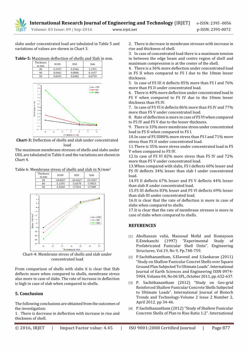
Slabs are analyzed to compare their results with the shells of the same dimension and thickness. Slabs of the dimension 1000mm X 700mm with the thickness of 20mm, 40mm and 50mm are analyzed under concentrated load. Slab before and after loading is shown in Figure 7. Results of the analysis are shown below. Under concentrated load Slabs are analyzed and the corresponding deflection and stress values are shown in Table 4.
Fig-7: Deflected shape of Slab before and after loading. Table-4: Deflection and Stress values of Slab I, Slab II and Slab III
Deflection of Slabs in mm Membrane stress of Slabs in N/mm2
Load in KN
Slab I Slab II Slab III Load in KN
Slab I Slab II Slab III
1 0.0146 0.0285 0.2278 1 -0.755 -1.1810 -4.704
2 0.0292 0.0571 0.4556 2 -1.507 -2.3621 -9.422
3 0.0437 0.0856 0.6835 3 -2.252 -3.5431 -14.13
4 0.0583 0.1141 0.9113 4 -3.015 -4.7242 -18.82
5 0.0729 0.1427 1.1391 5 -3.768 -5.9053 -23.55
The analysis results of each shell are compared between one another shells and slabs of same dimensions under concentrated load. The maximum deflection of shells and
International Research Journal of Engineering and Technology (IRJET) e-ISSN: 2395 -0056
Volume: 03 Issue: 09 | Sep-2016 www.irjet.net p-ISSN: 2395-0072
© 2016, IRJET | Impact Factor value: 4.45 | ISO 9001:2008 Certified Journal | Page 877
slabs under concentrated load are tabulated in Table 5 and variations of values are shown in Chart 3. Table-5: Maximum deflection of shells and Slab in mm.
Thickness in mm
R100 R50 Slab
20 0.1957 0.3546 1.1391
40 0.0461 0.0806 0.1427
50 0.0291 0.0482 0.0729
Chart-3: Deflection of shells and slab under concentrated
load The maximum membrane stresses of shells and slabs under UDL are tabulated in Table 6 and the variations are shown in Chart 4. Table 6: Membrane stress of shells and slab in N/mm2
Thickness in mm
R100 R50 Slab
20 -18.0057 -20.4427 -23.5507
40 -5.1295 -5.6678 -5.9053 50 -3.4260 -3.7016 -3.7689
Chart-4: Membrane stress of shells and slab under
concentrated load From comparison of shells with slabs it is clear that Slab deflects more when compared to shells, membrane stress also more in case of slabs. The rate of increase in deflection is high in case of slab when compared to shells.
5. Conclusion The following conclusions are obtained from the outcomes of the investigation: 1. There is decrease in deflection with increase in rise and thickness of shell.
2. There is decrease in membrane stresses with increase in rise and thickness of shell. 3. In case of concentrated load there is a maximum tension in between the edge beam and centre region of shell and maximum compression is at the center of the shell. 4. There is a 36% more deflection under concentrated load in FS II when compared to FS I due to the 10mm lesser thickness. 5. In case of FS III it deflects 85% more than FS I and 76% more than FS II under concentrated load. 6. There is 40% more deflection under concentrated load in FS V when compared to FS IV due to the 10mm lesser thickness than FS IV. 7. In case of FS VI it deflects 86% more than FS IV and 77% more than FS V under concentrated load. 8. Rate of deflection is more in case of FS VI when compared to FS IV and FS V due to the lesser thickness. 9. There is 33% more membrane stress under concentrated load in FS II when compared to FS I. 10. In case of FS III80% more stress than FS I and 71% more stress than FS II under concentrated load. 11. There is 35% more stress under concentrated load in FS V when compared to FS IV. 12. In case of FS VI 82% more stress than FS IV and 72% more than FS V under concentrated load. 13. When compared with slabs, FS I deflects 60% lesser and FS IV deflects 34% lesser than slab I under concentrated load. 14. FS II deflects 67% lesser and FS V deflects 44% lesser than slab II under concentrated load. 15. FS III deflects 83% lesser and FS VI deflects 69% lesser than slab III under concentrated load. 16. It is clear that the rate of deflection is more in case of slabs when compared to shells. 17. It is clear that the rate of membrane stresses is more in case of slabs when compared to shells.
REFERENCES [1] Abolhassan vafai, Massoud Mofid and Homayoon
E.Estekanchi (1997) “Experimental Study of Prefabricated Funicular Shell Units”. Engineering Structures, Vol.19, No 9, Pp.748-759.
[2] P.Sachithanantham, S.Elavenil and S.Sankaran (2011) “Study on Shallow Funicular Concret Shells over Square Ground Plan Subjected To Ultimate Loads”. International Journal of Earth Sciences and Engineering ISSN 0974-5904, Volume 04, No 06 SPL, October 2011, pp. 632-637.
[3] P. Sachithanantham (2012) “Study on Geo-grid Reinforced Shallow Funicular Concrete Shells Subjected to Ultimate Loads”. International Journal of Biotech Trends and Technology-Volume 2 Issue 2 Number 2, April 2012. pp 34-46.
[4] P.Sachithanantham (2012) “Study of Shallow Funicular Concrete Shells of Plan to Rise Ratio 1:2”. International
International Research Journal of Engineering and Technology (IRJET) e-ISSN: 2395 -0056
Volume: 03 Issue: 09 | Sep-2016 www.irjet.net p-ISSN: 2395-0072
© 2016, IRJET | Impact Factor value: 4.45 | ISO 9001:2008 Certified Journal | Page 878
Journal of Biotech Trends and Technology-Volume 2 Issue 3 Number 1, May 2012. pp 53-64.
[5] P.Sachithanantham (2012) “Study on Shallow Funicular Concrete Shells over Rectangular Ground Plan Ratio 1:0.6”. International Journal of Computer Trends and Technology-Volume 3 Issue 6 Number 2, December 2012. pp 19-28.
[6] P. Sachithanantham, Dr. S. Sankaran, Dr. S. Elavenil (2014) “Study On Shallow Funicular Concrete Shells over Rectangular Ground Plan Ratio 1:0.9”. International Journal of Emerging Technology and Advanced Engineering Volume 4, Special issue 4, june 2014, pp 102-107.
[7] P. Sachithanantham, Dr.S. Sankaran, Dr.S. Elavenil(2015) “Influence of Rise on Ultimate Load of Shallow Funicular Concrete Shells over Rectangular Ground Plan Ratio 1:0.6”. International Journal of Science and Engineering Research, Volume 6, Issue 7, July2015.
[8] P. Sachithanantham, S. Sankaran, S. Elavenil(2015) “Deflection Characteristics of Shallow Funicular Concrete Shells over Rectangular Ground Plan Ratio 1:0.5”. International Journal on Recent and Innovation Trends In Computing And Communication, Volume 3, Issue 7.
[9] S.Elangovan and A.R.Santhakumar (1988) “Parametric Study of Funicular Shells”. International Symposium on Innovative Application of Shells and Spatial Forms, pp.193-203
[10] Tongbram Tarunkumar and P.Sachithanantham (2012) “Study on Shallow Funicular Concrete Shells over Rectangular Ground Plan Ratio 1:0.8”. International Journal of Computer Trends and Technology-Volume 3 Issue 6 Number 2, December 2012. pp 29-49.
BIOGRAPHIES
Siddesh T M is presently studying M.Tech (Computer Aided Design of Structures) in UBDTCE, Davanagere, Karnataka. He received his B.E Degree in Civil Engineering from VTU during 2010-2014. His areas of research interest include FE analysis of concrete structures.
Harish B A is presently working as assistant professor, Dept of Civil Engineering at GMIT, Davangere, Karnataka. He obtained his M.Tech degree in Computer Aided Design of Structures from VTU. His areas of research interest include Fiber reinforced concrete and concrete shells.
Dr. K. Manjunatha is presently working as Chairman and Professor, Dept of Civil Engineering, UBDTCE, Davangere, Karnataka. He obtained his M.Sc(Engg) in Geotechnical Engineering from IISc, Bangalore, Karnataka and his PhD in Geotechnical Engineering from IISc Bangalore in 1998. His areas of research interest include geo-tech & foundation engineering and Geo-environmental engineering.