
Finite Element Analysis Method for Detection of the Corona ... · 5 Experimental Setup In order to...
6
Finite Element Analysis Method for Detection of the Corona Discharge Inception Voltage in a Wire-Cylinder Arrangement KONSTANTINOS N. KIOUSIS, ANTONIOS X. MORONIS, EMMANOUIL D. FYLLADITAKIS Technological Educational Institute (TEI) of Athens Energy Technology Department Ag. Spyridonos 12210 Aegaleo GREECE [email protected], [email protected], [email protected] Abstract: The inception voltage of the positive corona discharges (CIV) in a typical wire-cylinder electrode arrangement in air, under high voltage dc application, has been studied by implementing the Finite Element Analysis (FEA). Numerical analysis has been carried out on the electric field intensity, along the wire-cylinder gap axis, in order to determine the inception voltage of each air gap and define its dependence on geometrical characteristics of the electrodes. An experimental investigation has been conducted and used so as to justify the simulation results. The CIV was mainly associated to the wire radius, while the distance between the electrodes had a secondary importance. Finally, the inception voltage had slight changes for different cylinder radii. Key-Words: Finite Element Analysis (FEA), Corona Inception Voltage (CIV), Wire-cylinder arrangement 1 Introduction In recent years, the corona discharge phenomenon has been the subject of intensive studies [1-3]. Corona discharges have been a main concern for power transmission engineers because of the associated power loss, audible noise and signal interference [4]. On the other hand the sustainable corona discharge process is widely used as the source of unipolar ions in a number of commercial and industrial applications [5-8] and generally applications where small particle or droplet motion control is needed [9-11]. In any case, the main criterion is the threshold voltage in which the corona discharges initiate (Corona Inception Voltage) [12]. The corona inception voltage (CIV) has been investigated by Peek who thereby developed some well-known empirical formulae [13]. Successful attempts have been made since then, in order to relate the inception of the corona discharges with geometry and environmental parameters [14-17], but there is no study available for the parallel wire- cylinder arrangement. On the other hand, investigations by means of the electric field and potential distribution as well as the corona discharge current measurements, have already been conducted for wire-cylinder electrode pairs [18-20]. The goal of this paper is the fine modeling and analysis of the electric field strength in a wire- cylinder configuration in air, in order to define the threshold voltage of the corona discharges, considering the geometrical characteristics of the electrodes. 2 Corona Inception Voltage (CIV) Corona discharge is a process where current develops from an electrode, by ionizing the surrounding medium near sharp points or edges. The ionization region for parallel conductors can be calculated as [13]: 0.301 a r = ⋅ (1) where r [cm] is the radius of the emitter (wire). Once the field intensity is sufficient, the degree of field non-uniformity is high enough and free electrons are available in the overstressed field region a, corona discharges initiate. The threshold voltage (CIV) between two parallel conductors is given by Peek’s formula [13]: 0.301 1 ln u o d CIV m g r r r δ = ⋅ ⋅ + ⋅ ⋅ ⋅ (2) where m u represents the emitter’s roughness factor (m u =1 for smooth polished wires), g o is the air’s dielectric strength (~3 . 10 6 V/m), d [m] is the electrode gap and δ is the air density factor (for STP conditions, δ=1). As soon as the corona discharges initiate in the vicinity of the overstressed electrode (wire), space charge accumulates, which in turn produces current flow (corona discharge current) as ionized air molecules drift (corona gap) towards the collector (cylinder). Several numerical and experimental methods have been proposed for the determination of the CIV [21]. In the present study, simulation results will be compared with experimental findings in order to ensure the accuracy of the applied method. Recent Advances in Finite Differences and Applied & Computational Mathematics ISBN: 978-1-61804-184-5 188
-
Upload
truongnguyet -
Category
Documents
-
view
214 -
download
0
Transcript of Finite Element Analysis Method for Detection of the Corona ... · 5 Experimental Setup In order to...
Finite Element Analysis Method for Detection of the Corona Discharge
Inception Voltage in a Wire-Cylinder Arrangement
KONSTANTINOS N. KIOUSIS, ANTONIOS X. MORONIS, EMMANOUIL D. FYLLADITAKIS
Technological Educational Institute (TEI) of Athens
Energy Technology Department
Ag. Spyridonos 12210 Aegaleo
GREECE
[email protected], [email protected], [email protected]
Abstract: The inception voltage of the positive corona discharges (CIV) in a typical wire-cylinder electrode
arrangement in air, under high voltage dc application, has been studied by implementing the Finite Element
Analysis (FEA). Numerical analysis has been carried out on the electric field intensity, along the wire-cylinder
gap axis, in order to determine the inception voltage of each air gap and define its dependence on geometrical
characteristics of the electrodes. An experimental investigation has been conducted and used so as to justify the
simulation results. The CIV was mainly associated to the wire radius, while the distance between the electrodes
had a secondary importance. Finally, the inception voltage had slight changes for different cylinder radii.
Key-Words: Finite Element Analysis (FEA), Corona Inception Voltage (CIV), Wire-cylinder arrangement
1 Introduction In recent years, the corona discharge phenomenon
has been the subject of intensive studies [1-3].
Corona discharges have been a main concern for
power transmission engineers because of the
associated power loss, audible noise and signal
interference [4]. On the other hand the sustainable
corona discharge process is widely used as the
source of unipolar ions in a number of commercial
and industrial applications [5-8] and generally
applications where small particle or droplet motion
control is needed [9-11]. In any case, the main
criterion is the threshold voltage in which the corona
discharges initiate (Corona Inception Voltage) [12].
The corona inception voltage (CIV) has been
investigated by Peek who thereby developed some
well-known empirical formulae [13]. Successful
attempts have been made since then, in order to
relate the inception of the corona discharges with
geometry and environmental parameters [14-17],
but there is no study available for the parallel wire-
cylinder arrangement. On the other hand,
investigations by means of the electric field and
potential distribution as well as the corona discharge
current measurements, have already been conducted
for wire-cylinder electrode pairs [18-20].
The goal of this paper is the fine modeling and
analysis of the electric field strength in a wire-
cylinder configuration in air, in order to define the
threshold voltage of the corona discharges,
considering the geometrical characteristics of the
electrodes.
2 Corona Inception Voltage (CIV) Corona discharge is a process where current
develops from an electrode, by ionizing the
surrounding medium near sharp points or edges. The
ionization region for parallel conductors can be
calculated as [13]:
0.301a r= ⋅ (1)
where r [cm] is the radius of the emitter (wire).
Once the field intensity is sufficient, the degree
of field non-uniformity is high enough and free
electrons are available in the overstressed field
region a, corona discharges initiate. The threshold
voltage (CIV) between two parallel conductors is
given by Peek’s formula [13]:
0.3011 lnu o
dCIV m g r
r rδ = ⋅ ⋅ + ⋅ ⋅ ⋅
(2)
where mu represents the emitter’s roughness factor
(mu=1 for smooth polished wires), go is the air’s
dielectric strength (~3.10
6V/m), d [m] is the
electrode gap and δ is the air density factor (for STP
conditions, δ=1). As soon as the corona discharges
initiate in the vicinity of the overstressed electrode
(wire), space charge accumulates, which in turn
produces current flow (corona discharge current) as
ionized air molecules drift (corona gap) towards the
collector (cylinder).
Several numerical and experimental methods
have been proposed for the determination of the CIV
[21]. In the present study, simulation results will be
compared with experimental findings in order to
ensure the accuracy of the applied method.
Recent Advances in Finite Differences and Applied & Computational Mathematics
ISBN: 978-1-61804-184-5 188
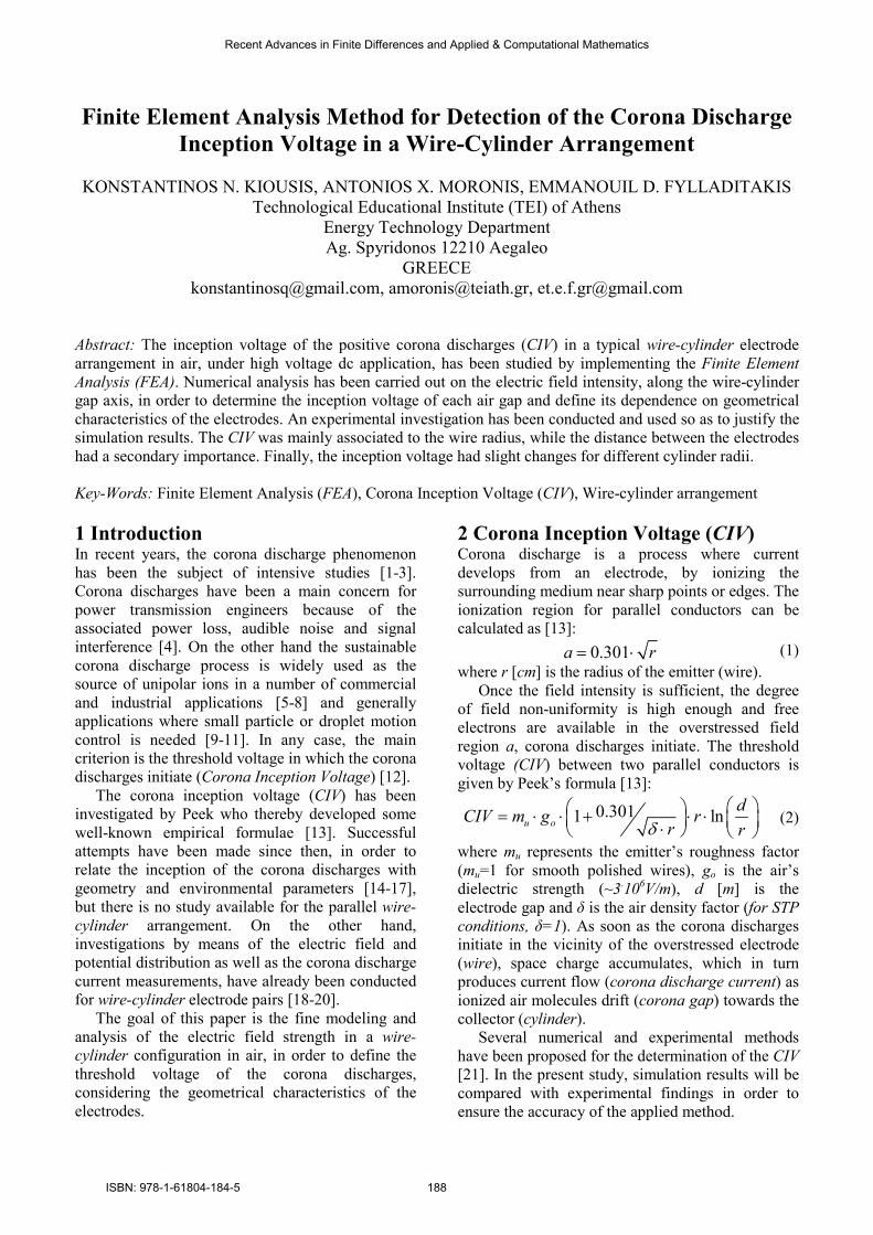
3 Electrode geometry and dimensions The electrode pair and its critical dimensions (wire
radius r, cylinder radius R and electrode gap d), are
shown in Fig. 1. Since the corona inception voltage
is strongly dependent on the electric field non-
uniformity, different R/r and d/r ratios have been
used as shown in table 1.
Fig. 1 The wire-cylinder electrode pair
Table 1 Geometrical characteristics and dimensions
Geometrical characteristic Dimensions
Gap distance d (cm) 1,2,3,4,5
Wire radius r (µm) 30,50,100,250,400
Cylinder radius R (mm) 5,10,15,20
R/r ratio 12.5 - 667
d/r ratio 75 - 1667
4 Numerical Model and Parameters A dedicated simulation software FEMM (ver.4.2),
implementing the Finite Element Analysis, has been
used for the present study. In our case, the steady
state electrostatics problem is governed by the well-
known Gauss’s and Poisson’s equations:
E V= −∇ (3)
2
0
V ρε∇ = − (4)
where E [V/m] is the electric field, V [V] is the
applied voltage, ρ [C/m3] is the space charge density
in the region, and ε0 represents the dielectric
permittivity of free space (~8.85.10
-12 F/m in air).
The electric field should satisfy the charge
conservation law:
0j∇⋅ = (5)
where j [A/m2] is the current density, defined as:
j Eρ µ= ⋅ ⋅ (6)
where µ [m2/V·s] is the dielectric’s ion mobility.
Equations (3-6) can be combined to obtain:
( )( ){ }2 0V V∇⋅ ∇ ∇ = (7)
FEMM solves (7), for potential V, over a user
defined domain with user defined sources and
boundary conditions. Due to the longitudinal axis
symmetry, the electric field distribution may only
change in the radial direction, along the electrode
gap thus, a 3-dimensional problem may be
minimized into a 2-dimensional problem that
requires a much smaller number of nodes and less
computing power. Hence, a 2-dimensional planar
electrostatic problem has been defined, with a solver
precision value of 10-8.
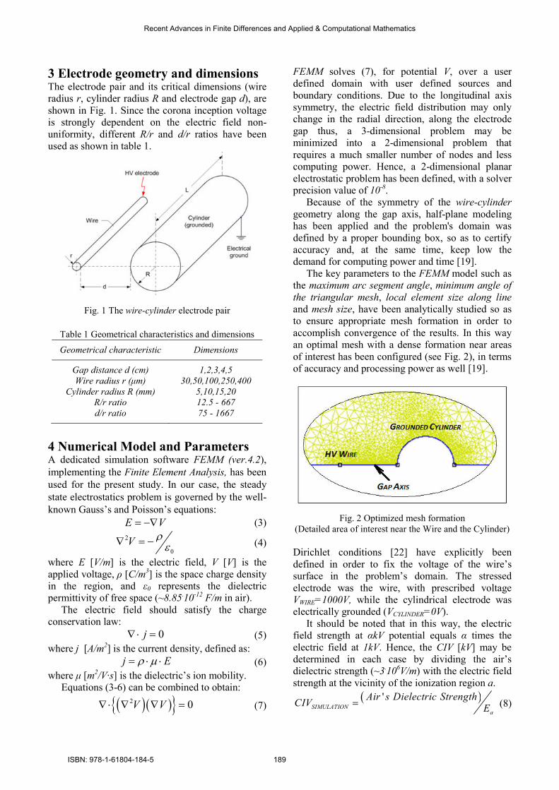
Because of the symmetry of the wire-cylinder
geometry along the gap axis, half-plane modeling
has been applied and the problem's domain was
defined by a proper bounding box, so as to certify accuracy and, at the same time, keep low the
demand for computing power and time [19].
The key parameters to the FEMM model such as
the maximum arc segment angle, minimum angle of
the triangular mesh, local element size along line
and mesh size, have been analytically studied so as
to ensure appropriate mesh formation in order to
accomplish convergence of the results. In this way
an optimal mesh with a dense formation near areas
of interest has been configured (see Fig. 2), in terms
of accuracy and processing power as well [19].
Fig. 2 Optimized mesh formation
(Detailed area of interest near the Wire and the Cylinder)
Dirichlet conditions [22] have explicitly been
defined in order to fix the voltage of the wire’s
surface in the problem’s domain. The stressed
electrode was the wire, with prescribed voltage
VWIRE=1000V, while the cylindrical electrode was
electrically grounded (VCYLINDER=0V). It should be noted that in this way, the electric
field strength at αkV potential equals α times the
electric field at 1kV. Hence, the CIV [kV] may be
determined in each case by dividing the air’s
dielectric strength (~3.10
6V/m) with the electric field
strength at the vicinity of the ionization region a.
( )' SIMULATION
a
Air s Dielectric StrengthCIV
E=
(8)
Recent Advances in Finite Differences and Applied & Computational Mathematics
ISBN: 978-1-61804-184-5 189
5 Experimental Setup In order to investigate the inception of the corona
discharges experimentally, a set of wire-cylinder
electrode pairs has been carefully prepared. Each
module consisted of a thin polished copper wire
with radius r (emitter) and an aluminum cylinder
(collector) with radius R, while the electrode length
was L. Both electrodes were fixed on a wooden
frame parallel to each other, at distance d (corona
gap) and placed in ambient air (dielectric medium).
Positive high dc voltage has been applied to the
emitter by an adjustable high voltage dc power
source (Matsusada Precision W Series), while the
collector was connected to the electrical ground.
The positive corona discharge current was measured
by a Metra Hit 28S precision multimeter connected
in series between the collector and the ground as
shown in Fig. 3.
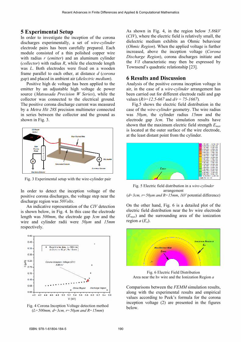
Fig. 3 Experimental setup with the wire-cylinder pair
In order to detect the inception voltage of the
positive corona discharges, the voltage step near the
discharge region was 50Volts.
An indicative representation of the CIV detection
is shown below, in Fig. 4. In this case the electrode
length was 500mm, the electrode gap 3cm and the
wire and cylinder radii were 50µm and 15mm
respectively.
Fig. 4 Corona Inception Voltage detection method
(L=500mm, d=3cm, r=50µm and R=15mm)
As shown in Fig. 4, in the region below 5.86kV
(CIV), where the electric field is relatively small, the
dielectric medium exhibits an Ohmic behaviour
(Ohmic Region). When the applied voltage is further
increased, above the inception voltage (Corona
Discharge Region), corona discharges initiate and
the V/I characteristic may then be expressed by
Townsend’s quadratic relationship [23].
6 Results and Discussion Analysis of the positive corona inception voltage in
air, in the case of a wire-cylinder arrangement has
been carried out for different electrode radii and gap
values (R/r÷12.5-667 and d/r ÷ 75-1667).
Fig.5 shows the electric field distribution in the
case of the wire-cylinder geometry. The wire radius
was 50µm, the cylinder radius 15mm and the
electrode gap 3cm. The simulation results have
shown that the maximum electric field strength Emax
is located at the outer surface of the wire electrode,
at the least distant point from the cylinder.
Fig. 5 Electric field distribution in a wire-cylinder
arrangement
(d=3cm, r=50µm and R=15mm, 1kV potential difference)
On the other hand, Fig. 6 is a detailed plot of the
electric field distribution near the hv wire electrode
(Emax) and the surrounding area of the ionization
region a (Ea).
Fig. 6 Electric Field Distribution
Area near the hv wire and the Ionization Region a
Comparisons between the FEMM simulation results,
along with the experimental results and empirical
values according to Peek’s formula for the corona
inception voltage (2) are presented in the figures below.
Recent Advances in Finite Differences and Applied & Computational Mathematics
ISBN: 978-1-61804-184-5 190
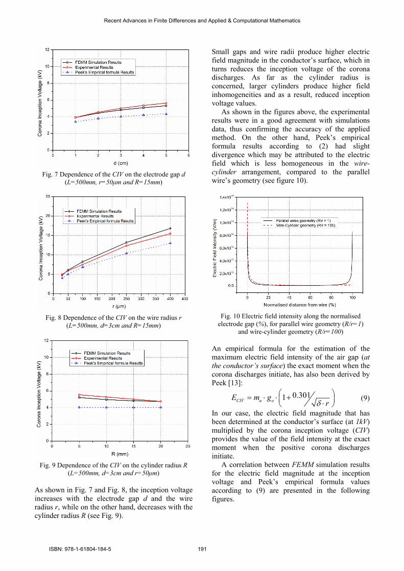
Fig. 7 Dependence of the CIV on the electrode gap d
(L=500mm, r=50µm and R=15mm)
Fig. 8 Dependence of the CIV on the wire radius r
(L=500mm, d=3cm and R=15mm)
Fig. 9 Dependence of the CIV on the cylinder radius R
(L=500mm, d=3cm and r=50µm)
As shown in Fig. 7 and Fig. 8, the inception voltage
increases with the electrode gap d and the wire
radius r, while on the other hand, decreases with the
cylinder radius R (see Fig. 9).
Small gaps and wire radii produce higher electric
field magnitude in the conductor’s surface, which in
turns reduces the inception voltage of the corona
discharges. As far as the cylinder radius is
concerned, larger cylinders produce higher field
inhomogeneities and as a result, reduced inception
voltage values.
As shown in the figures above, the experimental
results were in a good agreement with simulations
data, thus confirming the accuracy of the applied
method. On the other hand, Peek’s empirical
formula results according to (2) had slight
divergence which may be attributed to the electric
field which is less homogeneous in the wire-
cylinder arrangement, compared to the parallel
wire’s geometry (see figure 10).
Fig. 10 Electric field intensity along the normalised
electrode gap (%), for parallel wire geometry (R/r=1)
and wire-cylinder geometry (R/r=100)
An empirical formula for the estimation of the
maximum electric field intensity of the air gap (at
the conductor’s surface) the exact moment when the
corona discharges initiate, has also been derived by
Peek [13]:
0.3011CIV u oE m grδ
= ⋅ ⋅ + ⋅ (9)
In our case, the electric field magnitude that has
been determined at the conductor’s surface (at 1kV)
multiplied by the corona inception voltage (CIV)
provides the value of the field intensity at the exact
moment when the positive corona discharges
initiate.
A correlation between FEMM simulation results
for the electric field magnitude at the inception
voltage and Peek’s empirical formula values
according to (9) are presented in the following
figures.
Recent Advances in Finite Differences and Applied & Computational Mathematics
ISBN: 978-1-61804-184-5 191

Fig. 11 Emax at the Corona Inception Voltage
with the electrode gap d
(L=500mm, r=30µm and R=15mm)
Fig. 12 Emax at the Corona Inception Voltage with the
wire electrode radius r
(L=500mm, d=3cm and R=15mm)
Fig. 13 Emax at the Corona Inception Voltage with the
cylinder radius R
(L=500mm, d=3cm and r=25µm)
It can be seen in the figures above, that the electric
field intensity at the conductor’s surface (Emax in
each case), the exact moment when the corona
discharges initiate (CIV), depends only on the wire
radius r. This comes also in agreement with Peek’s
empirical formula values according to (9), which
coincide with the FEMM’s simulation results in all
cases.
7 Conclusions A study for the inception voltage of the positive
corona discharges (CIV) in a typical wire-cylinder
electrode arrangement in air, under high voltage dc
application, has been conducted by implementing
the Finite Element Analysis (FEA).
Detailed analysis has been carried out in the case
of the wire-cylinder arrangement, considering
different geometrical characteristics of the
electrodes such as the electrode gap d and the wire,
cylinder electrode radii r and R respectively.
The electric field intensity along the wire-
cylinder gap axis has been defined, in order to
determine the inception voltage in each case and an
experimental investigation has been conducted so as
to justify the simulation results.
The experimental results were in a good
agreement with the simulations data, thus
confirming the accuracy of the applied method.
Some slight divergences of the investigation results
with Peek’s empirical formula results (2) may be
attributed to the wire-cylinder inhomogeneous
electric field compared to the parallel wire’s
geometry.
Simulation and experimental results have shown
that the CIV was mainly associated to the wire
radius r, while the distance d between the electrodes
has a secondary importance. On the other hand, the
cylinder’s radius R seemed to have insignificant
affection to the inception of the positive corona
discharges.
References:
[1] M. Khalifa, High-Voltage Engineering Theory
and Practice, Marcel Dekker inc., New York, 1990.
[2] M.S. Naidu, V. Kamaraju, High Voltage
Engineering, Mc Graw Hill, New York, 1996.
[3] C.L. Wadhwa, High Voltage Engineering, New
Age International (P) Ltd., 2007.
[4] M. Abdel-Salam, P. Weiss and B. Lieske,
Discharges in air from point electrodes in the
presence of dielectric plates-experimental results,
27, (1992), pp. 309-319.
[5] K.S.P. Nikas, A.A. Varonos and G.C. Bergeles,
Numerical simulation of the flow and the collection
mechanisms inside a laboratory scale electrostatic
precipitator, J. Electrostatics, 63, (2005), 423-443.
Recent Advances in Finite Differences and Applied & Computational Mathematics
ISBN: 978-1-61804-184-5 192
[6] J.H. Kim, H.S. Lee, H.H. Kim and A. Ogata,
Electrospray with electrostatic precipitator enhances
fine particles collection efficiency, Journal of
Electrostatics, 68, (2010), 305-310.
[7] M. Barletta and A. Gisario, Electrostatic spray
painting of carbon fibre-reinforced epoxy
composites, Progress in Organic Coatings, 64,
(2009), 339-349.
[8] A. Jaworek and A.T. Sobczyk, Electrospraying
route to nanotechnology: An overview, Journal of
Electrostatics, 66, (2008), 197-219.
[9] M. Goldman, Corona discharges and their
applications, Physical Science Measurement and
Instrumentation, Management and Education -
Reviews, IEE Proceedings A, 128, (1981), 298-302.
[10] M. Goldman, A. Goldman and R.S. Sigfmond,
The corona discharge, its properties and specific
uses, Pure Appl Chem, 57, (1985), 1353-1362.
[11] J.S. Chang, P.A. Lawless and T. Yamamoto,
Corona discharge processes, Plasma Science IEEE
Transactions, 19, (1991), 1152-1166.
[12] B. Buchet, M. Goldman, A. Goldman, The
nature of the permanent current in point to plane
corona discharges with direct voltage, Journal of
Les Comptes Rendus de l'Académie des sciences,
263, (1966),356-359.
[13] F.W. Peek, Dielectric Phenomena in High
Voltage Engineering, McGraw-Hill Press, New
York, 1929.
[14] J.J. Lowke and F.D. Alessandro, Onset corona
fields and electrical breakdown criteria, J. Appl.
Phys., 28, (2003), 2673-2682.
[15] D.B. Phillips, R.G. Olsen and P.D. Pedrow,
Corona onset as a design optimization criterion for
high voltage hardware, IEEE Trans. Dielectric
Electrical Insulation, 7 (6), (2000), 744-751.
[16] V. Amoruso and F. lattarulo, Accurate
extension of Peek’s law to stranded conductors,
European Transactions in Electrical Power, 1, (1),
(1991), 15-20.
[17] K. Yamazaki and R.G. Olsen, Application of a
corona onset criterion to calculation of corona onset
voltage of stranded conductors, IEEE Transactions.
Dielectrics and Electrical Insulations, 11, (4),
(2004), 674-680.
[18] K.N. Kiousis, A.X. Moronis, Experimental
Investigation of EHD Flow in Wire to Cylinder
Electrode Configuration, in: 10th IASTED
European Conference on Power and Energy
Systems, Crete, 2011, pp. 21-26.
[19] K.N. Kiousis and A.X. Moronis, Modeling and
Analysis of the Electric Field and Potential
Distribution in a Wire-Cylinder Air Gap, Recent
Researches in Information Science and
Applications, WSEAS International Conference,
2013, pp. 35-40.
[20] K. Kantouna, G.P. Fotis, K.N. Kiousis, L.
Ekonomou and G.E. Chatzarakis, Analysis of a
Cylinder-Wire-Cylinder Electrode Configuration
during Corona Discharge, in: CSCCA, WSEAS,
2012, pp. 204-208.
[21] L. Chen,, J.M.K. MacAlpine, X. Bian, L. Wang
and Z. Guan, Comparison of methods for
determining corona inception voltages of
transmission line conductors, Journal of
Electrostatics, 2012, pp. 1-7.
[22] I. Hlavacek and M. Krizek, On a super
convergent finite element scheme for elliptic
systems. I. Dirichlet boundary condition,
Applications of Mathematics, 32, (1987), 131-154.
[23] J.S. Townsend, Electricity in gases, Oxford
University press, New York, 1915.
Recent Advances in Finite Differences and Applied & Computational Mathematics
ISBN: 978-1-61804-184-5 193