Fingerprint base security system
41
FINGERPRINT BASED SECURITY SYSTEM BALAJI INSTITUTE OF ENGINEERING & TECHNOLOGY PAGE 1 CHAPTER:-1 INTRODUCTION
-
Upload
praful-borad -
Category
Engineering
-
view
618 -
download
3
Transcript of Fingerprint base security system

FINGERPRINT BASED SECURITY SYSTEM
BALAJI INSTITUTE OF ENGINEERING & TECHNOLOGY PAGE 1
CHAPTER:-1
INTRODUCTION

FINGERPRINT BASED SECURITY SYSTEM
BALAJI INSTITUTE OF ENGINEERING & TECHNOLOGY PAGE 2
INTRODUCTION
In today‘s regular life there are many problems of common companies and other
security for home application and there are also important applications of automatic control
in many applications, so we dedicate this project to this common man and other industries.
Nowadays accurate personal identification is becoming more and more important.
Currently fingerprint recognition is the most widely used technique for personal
identification. Fingerprints are made up of locally parallel ridges with singular points, and
they constitute a unique permanent universal pattern. The use of ink and paper to get an
image from a finger was used for a long time, but technological advances have enabled to
automate the acquisition stage by means of solid-state sensors.
These sensors exploit different techniques to acquire the image (pressure, electrical
field, temperature…) and require a static (matrix sensor) or mobile finger position (sweeping
mode sensor).Our project is developed to provide security for an Organization. In this project
the fingerprint sensor sense the thumb impression of the corresponding person and that image
will be compared with registered image, if the both images are unique, then the finger
print device act ivates particular task like access control to a secured area,
ident ificat ion of the employee etc.
The project contains 2 modes, the first one is master mode and the second is user
mode. The master mode is used to register the new user and gives the mode of authorization.
The master mode has the ability to create and delete the users.
The user mode is an ordinary mode used for the authentication of the employees. In
user mode of authorization, creation and deletion of a user cannot be performed. The master
mode operations are done directly through interfacing the finger print module to the com port
of the computer.
The Microcontroller 89S52 is programmed to operate under user mode.
Microcontroller is programmed using C51 cross compiler. Fingerprint image is scanned by
the fingerprint device. If the scanned image matches with the registered image then
Microcontroller sends the authorized persons Id to the computer when the person enters and
leaves the organization.
Finger print based security system can be used at many places like Industries, Offices,
and Colleges or even at our home. This project is a fine combination of ―Biometrics
technology‖ and ―Embedded system technology‖. Fingerprint sensor is the main part of this
system. It makes use of Biometric sensor to detect fingerprint. It is also called as Biometric
sensor. Fingerprint sensor uses various types of techniques like ultrasonic method, optical
method or thermal technique. In this project we have used optical fingerprint sensor.

FINGERPRINT BASED SECURITY SYSTEM
BALAJI INSTITUTE OF ENGINEERING & TECHNOLOGY PAGE 3
CHAPTER:-2
BLOCK DIAGRAM

FINGERPRINT BASED SECURITY SYSTEM
BALAJI INSTITUTE OF ENGINEERING & TECHNOLOGY PAGE 4
2.1 BLOCK DIAGRAM
Fig. 2.1 Block Diagram
2.2 BLOCK DIAGRAM EXPLANATION
2.2.1 Display 16*2
LCD (Liquid Crystal Display) screen is an electronic display module and find
a wide range of applications.
A 16x2 LCD display is very basic module and is very commonly used in
various devices and circuits.
A 16x2 LCD means it can display 16 characters per line and there are 2 such
lines.
2.2.2 Fingerprint sensor
Here fingerprint module is used to scan the fingerprint and send to the
microcontroller and verifying the scanned fingerprint with the stored
fingerprint.
When coming fingerprint matches with the stored fingerprint Then the Relay
is complemented. Also the fingerprint ID is displayed over the LCD display.
We have used R305 Finger Print Sensor. It has an Optical biometric
fingerprint reader. It also has inbuilt flash memory. It performs the function of
image processing and gives out data on its output pin.

FINGERPRINT BASED SECURITY SYSTEM
BALAJI INSTITUTE OF ENGINEERING & TECHNOLOGY PAGE 5
2.2.3 Microcontroller 8051
The AT89S52 is a low-power, high-performance CMOS 8-bit microcontroller
with 8Kbytes of in-system programmable Flash memory.
The device is manufactured using Atmel‘s high-density nonvolatile memory
technology and is compatible with the industry-standard 80C51 instruction set
and pin out.
2.2.4 Relay driver
The relay is complemented and locker system is connected with relay so locker
is opened.
2.2.5 Power supply
Here in our project used 5v & 12 v supply used, 12v supply used for relay
driver and 5v used to each other components.
The microcontroller and other devices get power supply from AC TO DC
adapter through 7805, 5volts regular

FINGERPRINT BASED SECURITY SYSTEM
BALAJI INSTITUTE OF ENGINEERING & TECHNOLOGY PAGE 6
CHAPTER:-3
CIRCUIT DESCRIPTION

FINGERPRINT BASED SECURITY SYSTEM
BALAJI INSTITUTE OF ENGINEERING & TECHNOLOGY PAGE 7
3.1 CIRCUIT DIAGRAM
Fig.3.1 Circuit Diagram

FINGERPRINT BASED SECURITY SYSTEM
BALAJI INSTITUTE OF ENGINEERING & TECHNOLOGY PAGE 8
3.2 WORKING
When a finger is kept at the finger print reader, it is scanned by the fingerprint device.
It will give the information accordingly to microcontroller if the scanned image matches with
the registered image then which is displayed on the LCD. And the locker system interfaced to
the microcontroller responds accordingly. And if the information provided by the user is
incorrect or mismatch in finger prints is detected then access is denied.
The output received from fingerprint sensor to Microcontroller then compares these
output data. Function of microcontroller is to turn on the respective device depending upon
the input received. In case of OK signal from fingerprint module, microcontroller turns on
Relay and a Motor. However if the error output is received then it turns on the Buzzer.
It contains all the necessary electronics to allow you to store, delete, and verify
fingerprints with just the touch of a button. Stored fingerprints are retained even in the event
of complete power failure or battery drain. This eliminates the need for keeping track of keys
or remembering a combination password. It can only be opened when an authorized user is
present, since there are no keys or combinations to be copied or stolen, or locks that can be
picked.
In this project the fingerprint module from Miaxis Biometrics is used. It can store up
to 265 finger prints on its own memory. It can be controlled through its serial port.
You can add a fingerprint, Delete a fingerprint and identify the fingerprint.
To add a fingerprint, just show the finger on the module and press the ADD key.
Now the microcontroller will send the ADD command to the module and the module
will add it into the memory.
To delete the finger follow the same as above.
To identify the finger, press the Identify button and if the finger matches then the
Relay is complemented. Also the fingerprint ID is displayed over the LCD display.

FINGERPRINT BASED SECURITY SYSTEM
BALAJI INSTITUTE OF ENGINEERING & TECHNOLOGY PAGE 9
3.3 COMPONENT LIST
COMPONENT NAME NUMBER OF USE
Resistor
3 R1,R2,R3-----10K
2 R4,R5-----2.2K
1 R6-----56E
1 R7-----56K
1 10k SIP
capacitor
2 C1,C2-----33p
1 C3-----1micro
Ic 1 AT89S52
Transistor 2 BC 547
Crystal 1 11.0592MHz
Fingerprint module 1 R-305
Display 1 16*2
Ic socket 1 40 pin
Buzzer 1
switch 4 Push button
Relay 1
3.1 table of component
FINGERPRINT BASED SECURITY SYSTEM
BALAJI INSTITUTE OF ENGINEERING & TECHNOLOGY PAGE 10
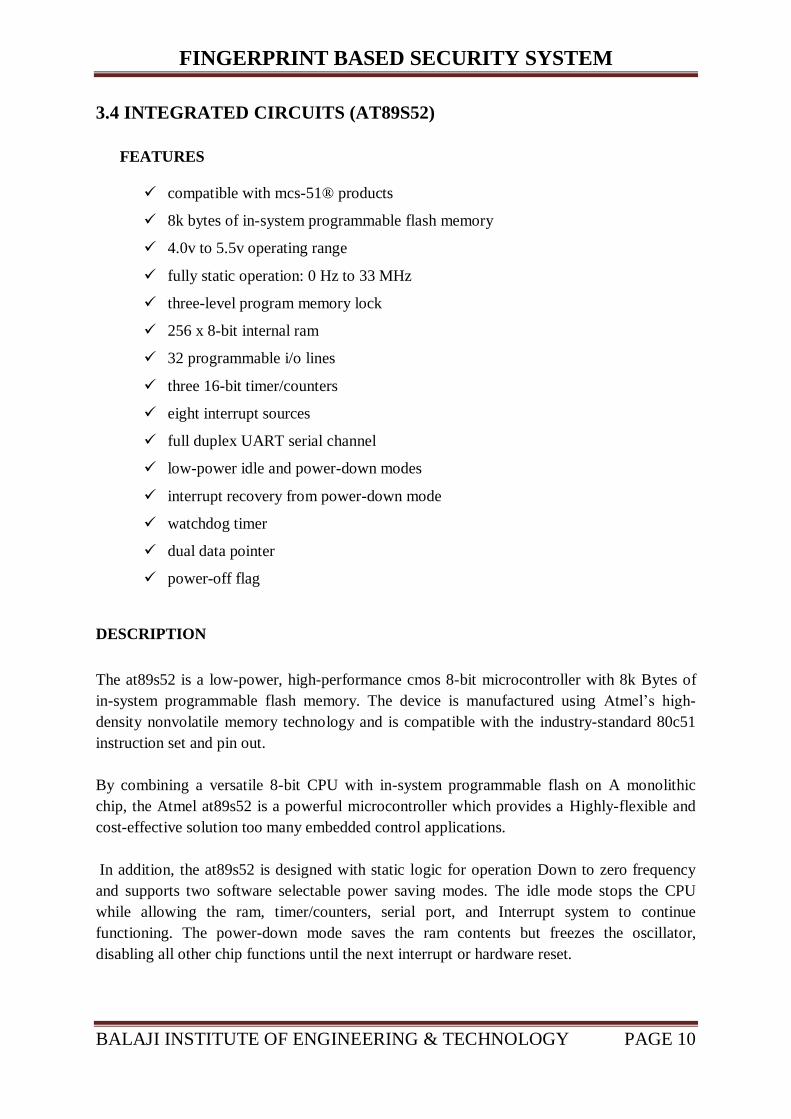
3.4 INTEGRATED CIRCUITS (AT89S52)
FEATURES
compatible with mcs-51® products
8k bytes of in-system programmable flash memory
4.0v to 5.5v operating range
fully static operation: 0 Hz to 33 MHz
three-level program memory lock
256 x 8-bit internal ram
32 programmable i/o lines
three 16-bit timer/counters
eight interrupt sources
full duplex UART serial channel
low-power idle and power-down modes
interrupt recovery from power-down mode
watchdog timer
dual data pointer
power-off flag
DESCRIPTION
The at89s52 is a low-power, high-performance cmos 8-bit microcontroller with 8k Bytes of
in-system programmable flash memory. The device is manufactured using Atmel‘s high-
density nonvolatile memory technology and is compatible with the industry-standard 80c51
instruction set and pin out.
By combining a versatile 8-bit CPU with in-system programmable flash on A monolithic
chip, the Atmel at89s52 is a powerful microcontroller which provides a Highly-flexible and
cost-effective solution too many embedded control applications.
In addition, the at89s52 is designed with static logic for operation Down to zero frequency
and supports two software selectable power saving modes. The idle mode stops the CPU
while allowing the ram, timer/counters, serial port, and Interrupt system to continue
functioning. The power-down mode saves the ram contents but freezes the oscillator,
disabling all other chip functions until the next interrupt or hardware reset.

FINGERPRINT BASED SECURITY SYSTEM
BALAJI INSTITUTE OF ENGINEERING & TECHNOLOGY PAGE 11
Fig. 3.4.1 Block Diagram of IC

FINGERPRINT BASED SECURITY SYSTEM
BALAJI INSTITUTE OF ENGINEERING & TECHNOLOGY PAGE 12
FIGURE 3.4.2 Pin Diagram
PIN DESCRIPTION
VCC:-Supply voltage.
GND:-Ground.
RST:-Reset input. A high on this pin for two machine cycles while the oscillator is running
resets the device. This pin drives High for 96 oscillator periods after the Watchdog times out.
The DISRTO bit in SFR AUXR (address 8EH) can be used to disable this feature. In the
default state of bit DISRTO, The RESET HIGH out feature is enabled
ALE/PROG:-Address Latch Enable (ALE) is an output pulse for latching the low byte of the
address during accesses to external memory. This pin is also the program pulse input (PROG)
during Flash programming. If desired, ALE operation can be disabled by setting bit 0 of SFR
location 8EH. With the bit set, ALE is active only during MOVX or MOVC instruction.
Otherwise, the pin is weakly pulled high. Setting the ALE-disable bit has no effect if the
microcontroller is in external execution mode.
PSEN:-Program Store Enable (PSEN) is the read strobe to external program memory. When
the AT89S52 is executing code from external program memory, PSEN is activated twice
each machine cycle, except that two PSEN activations are skipped during each access to
external data memory.

FINGERPRINT BASED SECURITY SYSTEM
BALAJI INSTITUTE OF ENGINEERING & TECHNOLOGY PAGE 13
3.2 Table of IC pin Descriptions
.
Pin No Function Name
1
8 bit input/output port (P1) pins
P1.0
2 P1.1
3 P1.2
4 P1.3
5 P1.4
6 P1.5
7 P1.6
8 P1.7
9 Reset pin; Active high Reset
10 Input (receiver) for serial communication RxD
8 bit input/output
port (P3) pins
P3.0
11 Output (transmitter) for serial
communication TxD P3.1
12 External interrupt 1 Int0 P3.2
13 External interrupt 2 Int1 P3.3
14 Timer1 external input T0 P3.4
15 Timer2 external input T1 P3.5
16 Write to external data memory Write P3.6
17 Read from external data memory Read P3.7
18 Quartz crystal oscillator (up to 24 MHz)
Crystal 2
19 Crystal 1
20 Ground (0V) Ground
21
8 bit input/output port (P2) pins
/
High-order address bits when interfacing with external memory
P2.0/ A8
22 P2.1/ A9
23 P2.2/ A10
24 P2.3/ A11
25 P2.4/ A12
26 P2.5/ A13
27 P2.6/ A14
28 P2.7/ A15
29 Program store enable; Read from external program memory PSEN
30 Address Latch Enable ALE
Program pulse input during Flash programming Prog
31 External Access Enable; Vcc for internal program executions EA
Programming enable voltage; 12V (during Flash programming) Vpp
32
8 bit input/output port (P0) pins
Low-order address bits when interfacing with external memory
P0.7/ AD7
33 P0.6/ AD6
34 P0.5/ AD5
35 P0.4/ AD4
36 P0.3/ AD3
37 P0.2/ AD2
38 P0.1/ AD1
39 P0.0/ AD0
40 Supply voltage; 5V (up to 6.6V) Vcc

FINGERPRINT BASED SECURITY SYSTEM
BALAJI INSTITUTE OF ENGINEERING & TECHNOLOGY PAGE 14
EA/VPP:-External Access Enable. EA must be strapped to GND in order to enable the
device to fetch code from external program memory locations starting at 0000H up to
FFFFH. Note, however, that if lock bit 1 is programmed, EA will be internally latched on
reset. EA should be strapped to VCC for internal program executions. This pin also receives
the 12-volt programming enable voltage (VPP) during Flash programming.
XTAL1:-Input to the inverting oscillator amplifier and input to the internal clock operating
circuit.
XTAL2:-Output from the inverting oscillator amplifier.
PORT 0:-
Port 0 is an 8-bit open drain bidirectional I/O port. As an output port, each pin can
sink eight TTL inputs. When 1sare written to port 0 pins, the pins can be used as high
impedance inputs.
Port 0 can also be configured to be the multiplexed low order address/data bus during
accesses to external program and data memory. In this mode, P0 has internal pull-ups.
Port 0 also receives the code bytes during Flash programming and outputs the code
bytes during program verification. External pull-ups are required during program
verification.
3.3 Alternate Function of P1
PORT 1:-
Port 1 is an 8-bit bidirectional I/O port with internal pull-ups. The Port 1 output
buffers can sink/source four TTL inputs. When 1s are written to Port 1 pins, they are
pulled high by the internal pull-ups and can be used as inputs. As inputs, Port 1 pins
that are externally being pulled low will source current (IIL) because of the internal
pull-ups.
In addition, P1.0 and P1.1 can be configured to be the timer/counter 2 external count
input (P1.0/T2) and the timer/counter 2 trigger input (P1.1/T2EX), respectively, as
shown in the following table.
Port 1 also receives the low-order address bytes during Flash programming and
verification.

FINGERPRINT BASED SECURITY SYSTEM
BALAJI INSTITUTE OF ENGINEERING & TECHNOLOGY PAGE 15
PORT 2:-
Port 2 is an 8-bit bidirectional I/O port with internal pull-ups. The Port 2 output
buffers can sink/source four TTL inputs. When 1s are written to Port 2 pins, they are
pulled high by the internal pull-ups and can be used as inputs. As inputs, Port 2 pins
that are externally being pulled low will source current (IIL) because of the internal
pull-ups.
Port 2 emits the high-order address byte during fetches from external program
memory and during accesses to external data memory that uses 16-bit addresses
(MOVX @DPTR). In this application, Port 2 uses strong internal pull-ups when
emitting 1s. During accesses to external data memory that use 8-bit addresses
(MOVX @ RI), Port 2emits the contents of the P2 Special Function Register.
Port 2 also receives the high-order address bits and some control signals during Flash
programming and verification.
PORT 3:-
Port 3 is an 8-bit bidirectional I/O port with internal pull-ups. The Port 3 output
buffers can sink/source four TTL inputs. When 1s are written to Port 3 pins, they are
pulled high by the internal pull-ups and can be used as inputs. As inputs, Port 3 pins
that are externally being pulled low will source current (IIL) because of the pull-ups.
Port 3 also serves the functions of various special features of the AT89S52, as shown
in the following table.
Port 3 also receives some control signals for Flash programming and verification.
3.4 Alternate Function of P3

FINGERPRINT BASED SECURITY SYSTEM
BALAJI INSTITUTE OF ENGINEERING & TECHNOLOGY PAGE 16
3.5 FINGERPRINT MODULE
Fig.3.5.1 Fingerprint Module
SPECIFICATIONS:
Fingerprint sensor type: Optical
Sensor Life: 100 million times
Static indicators: 15KVBacklight: bright green
Interface: USB1.1/UART(TTL logical level)
RS232 communication baud rate: 4800BPS~115200BPS changeable
Dimension: 55*32*21.5mm
Image Capture Surface 15—18(mm)
Verification Speed: 0.3 sec
Scanning Speed: 0.5 sec
Character file size: 256 bytes
Template size: 512 bytes
Storage capacity: 250
Security level: 5 (1,2,3,4,5(highest))
False Acceptance Rate (FAR) :0.0001%
False Rejection Rate (FRR): 0.1%
Resolution 500 DPI
Voltage :3.6-6.0 VDC
Working current: Typical 90 mA, Peak 150mA
Matching Method: 1: N
Operating Environment Temperature: -20 to 45° centigrade
FINGERPRINT BASED SECURITY SYSTEM
BALAJI INSTITUTE OF ENGINEERING & TECHNOLOGY PAGE 17
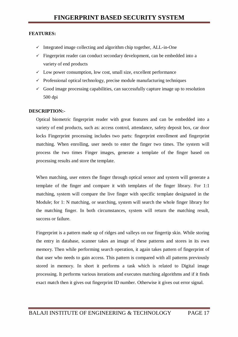
FEATURES:
Integrated image collecting and algorithm chip together, ALL-in-One
Fingerprint reader can conduct secondary development, can be embedded into a
variety of end products
Low power consumption, low cost, small size, excellent performance
Professional optical technology, precise module manufacturing techniques
Good image processing capabilities, can successfully capture image up to resolution
500 dpi
DESCRIPTION:-
Optical biometric fingerprint reader with great features and can be embedded into a
variety of end products, such as: access control, attendance, safety deposit box, car door
locks Fingerprint processing includes two parts: fingerprint enrollment and fingerprint
matching. When enrolling, user needs to enter the finger two times. The system will
process the two times Finger images, generate a template of the finger based on
processing results and store the template.
When matching, user enters the finger through optical sensor and system will generate a
template of the finger and compare it with templates of the finger library. For 1:1
matching, system will compare the live finger with specific template designated in the
Module; for 1: N matching, or searching, system will search the whole finger library for
the matching finger. In both circumstances, system will return the matching result,
success or failure.
Fingerprint is a pattern made up of ridges and valleys on our fingertip skin. While storing
the entry in database, scanner takes an image of these patterns and stores in its own
memory. Then while performing search operation, it again takes pattern of fingerprint of
that user who needs to gain access. This pattern is compared with all patterns previously
stored in memory. In short it performs a task which is related to Digital image
processing. It performs various iterations and executes matching algorithms and if it finds
exact match then it gives out fingerprint ID number. Otherwise it gives out error signal.

FINGERPRINT BASED SECURITY SYSTEM
BALAJI INSTITUTE OF ENGINEERING & TECHNOLOGY PAGE 18
SERIAL COMMUNICATION:-
When the FP module communicates with user device, definition of J1 is as follows:
3.5 Table of fingerprint Module Pin Descriptions
Precautions to be taken while accessing fingerprint sensor:
Fig.3.5.2 Correct way to access Fingerprint sensor
\
Pin
Number
Name Type Function Description
1 Vin INPUT Power input
2 GND - Signal ground. Connected to
power ground
3 TD INPUT Data output. TTL logical level
4 RD OUTPUT Out Data input. TTL logical
level

FINGERPRINT BASED SECURITY SYSTEM
BALAJI INSTITUTE OF ENGINEERING & TECHNOLOGY PAGE 19
3.6 TRANSISTOR (BC 547)
Fig.3.6.1 Transistor
BC547 is an NPN bi-polar junction transistor. A transistor, stands for transfer of resistance, is
commonly used to amplify current. A small current at its base controls a larger current at
collector & emitter terminals.
BC547 is mainly used for amplification and switching purposes. It has a maximum current
gain of 800. Its equivalent transistors are BC548 and BC549.
The transistor terminals require a fixed DC voltage to operate in the desired region of its
characteristic curves. This is known as the biasing. For amplification applications, the
transistor is biased such that it is partly on for all input conditions. The input signal at base is
amplified and taken at the emitter. BC547 is used in common emitter configuration for
amplifiers. The voltage divider is the commonly used biasing mode. For switching
applications, transistor is biased so that it remains fully on if there is a signal at its base. In
the absence of base signal, it gets completely off.
A BC547 transistor is a negative-positive-negative (NPN) transistor that is used for many
purposes. Together with other electronic components, such as resistors, coils, and capacitors,
it can be used as the active component for switches and amplifiers. Like all other NPN
transistors, this type has an emitter terminal, a base or control terminal, and a collector
terminal. In a typical configuration, the current flowing from the base to the emitter controls
the collector current. A short vertical line, which is the base, can indicate the transistor
schematic for an NPN transistor, and the emitter, which is a diagonal line connecting to the
base, is an arrowhead pointing away from the base.

FINGERPRINT BASED SECURITY SYSTEM
BALAJI INSTITUTE OF ENGINEERING & TECHNOLOGY PAGE 20
3.7 CRYSTAL (11.0592 MHZ)
Fig.3.7.1 Crystal
Crystal oscillators can be manufactured for oscillation over a wide range of frequencies, from
a few kilohertz up to several hundred megahertz. Many applications call for a crystal
oscillator frequency conveniently related to some other desired frequency, so hundreds of
standard crystal frequencies are made in large quantities and stocked by electronics
distributors. Using frequency dividers, frequency multipliers and phase locked loop circuits;
it is practical to derive a wide range of frequencies from one reference frequency.
You can use other frequencies such as 12 MHz, but according to the referenced site,
11.0592MHz is used because:
"it can be divided to give you exact clock rates for most of the common baud rates for the
UART, especially for the higher speeds (9600, 19200). Despite the "oddball" value, these
crystals are readily available and commonly used."
This is a Standard 11.0592MHz quartz crystal in HC49 casing. Every Microcontroller has
inbuilt oscillator circuit, connecting this quartz crystal with controller forms the crystal
oscillator circuit which provide the desired frequency to the processor. This odd value
11.0592 MHz crystal is perfectly divisible for generating standard baud rate for serial
communication with PC.

FINGERPRINT BASED SECURITY SYSTEM
BALAJI INSTITUTE OF ENGINEERING & TECHNOLOGY PAGE 21
3.8 DISPLAY
Fig.3.8.1 Display
Pin
No Function Name
1 Ground (0V) Ground
2 Supply voltage; 5V (4.7V – 5.3V) Vcc
3 Contrast adjustment; through a variable resistor VEE
4 Selects command register when low; and data register when high Register Select
5 Low to write to the register; High to read from the register Read/write
6 Sends data to data pins when a high to low pulse is given Enable
7
8-bit data pins
DB0
8 DB1
9 DB2
10 DB3
11 DB4
12 DB5
13 DB6
14 DB7
15 Backlight VCC (5V) Led+
16 Backlight Ground (0V) Led-
3.6 Pin description of Display

FINGERPRINT BASED SECURITY SYSTEM
BALAJI INSTITUTE OF ENGINEERING & TECHNOLOGY PAGE 22
A 16x2 LCD means it can display 16 characters per line and there are 2 such lines. In this
LCD each character is displayed in 5x7 pixel matrix. This LCD has two registers, namely,
Command and Data.
Command register stores the command instructions given to the LCD. A command is an
instruction given to LCD to do a predefined task like initializing it, clearing its screen, setting
the cursor position, controlling display etc. The data register stores the data to be displayed
on the LCD. The data is the ASCII value of the character to be displayed on the LCD
LCDs are used in a wide range of applications including computer monitors, televisions,
instrument panels, aircraft cockpit displays, and signage. They are common in consumer
devices such as video players, gaming devices, clocks, watches, calculators, and telephones,
and have replaced cathode ray tube (CRT) displays in most applications. They are available
in a wider range of screen sizes than CRT and plasma displays.
The LCD screen is more energy efficient and can be disposed of more safely than a CRT. Its
low electrical power consumption enables it to be used in battery-powered electronic
equipment. It is an electronically modulated optical device made up of any number of
segments filled with liquid crystals and arrayed in front of a light source (backlight) or
reflector to produce images in colour or monochrome. Liquid crystals were first discovered in
1888.[2]
By 2008, annual sales of televisions LCD screens exceeded sales of CRT units
worldwide; the CRT became obsolescent for most purposes. With

FINGERPRINT BASED SECURITY SYSTEM
BALAJI INSTITUTE OF ENGINEERING & TECHNOLOGY PAGE 23
3.9 BUZZER
Fig.3.9.1 Buzzer
A buzzer or beeper is an audio signalling device, which may be mechanical,
electromechanical, or piezoelectric. Typical uses of buzzers and beepers include alarm
devices, timers and confirmation of user input such as a mouse click or keystroke.
Audio transducers and buzzers convert electrical energy into acoustic energy. These devices
are found in smoke detectors and other products that produce sound. Some audio transducers,
like the one in the video below, are programmable and are capable of producing a series of
multiple tones.
3.10 NETWORK RESISTOR (10K)
Fig.3.10.1 NETWORK RESISTOR
Network resistor is a passive circuit element that is a combination of multiple resistances. It
forms a convenient solution when the user needs multiple resistances while constructing a
circuit. The manner in which the constituent resistances are combined can vary according to
the circuit requirement.
Hence, this type of resistor can be used to condense the circuit with additional benefits of low
costs and improved resistance tolerance matching.
Network Resistor is may used for speed up the process of Input Output ports.

FINGERPRINT BASED SECURITY SYSTEM
BALAJI INSTITUTE OF ENGINEERING & TECHNOLOGY PAGE 24
3.11 RELAY
Fig.3.11.1 Relay
Relays are switches that open and close circuits electromechanically or electronically. Relays
control one electrical circuit by opening and closing contacts in another circuit. As relay
diagrams show, when a relay contact is normally open (NO), there is an open contact when
the relay is not energized. When a relay contact is Normally Closed (NC), there is a closed
contact when the relay is not energized. In either case, applying electrical current to the state
contacts will change their.
Relays are generally used to switch smaller currents in a control circuit and do not usually
control power consuming devices except for small motors and Solenoids that draw low amps.
Nonetheless, relays can "control" larger voltages and amperes by having an amplifying effect
because a small voltage applied to a relays coil can result in a large voltage being switched by
the contacts.
Protective relays can prevent equipment damage by detecting electrical abnormalities,
including over current, undercurrent, overloads and reverse currents. In addition, relays are
also widely used to switch starting coils, heating elements, pilot lights and audible alarms.

FINGERPRINT BASED SECURITY SYSTEM
BALAJI INSTITUTE OF ENGINEERING & TECHNOLOGY PAGE 25
CHAPTER:-4
SIMULATION REPORT

FINGERPRINT BASED SECURITY SYSTEM
BALAJI INSTITUTE OF ENGINEERING & TECHNOLOGY PAGE 26
4.1 SIMULATION REPORT

FINGERPRINT BASED SECURITY SYSTEM
BALAJI INSTITUTE OF ENGINEERING & TECHNOLOGY PAGE 27

FINGERPRINT BASED SECURITY SYSTEM
BALAJI INSTITUTE OF ENGINEERING & TECHNOLOGY PAGE 28
4.2 ADVANTAGES
Fingerprint based security system is most secured system as compared to other
systems. Reason is that RFID card or Keys of lock can be stolen, password may be
leaked. However thumbnail of every human being is unique, so lock will not open
unless the same person is present to give the impression of fingerprint.
No need to remember the password or any Pin number.
One of the main advantages is that this system remembers the stored password even
if the power supply is turned off.
Scientific research and studies have proved that fingerprints do not change as you
grow up.
Using Fingerprint saves time to gain access as compared to other methods like RFID
card, Password or Key.
It can only be opened when an authorized user is present.
most secure and accurate than traditional password
Password based security system has always the threat of being stolen and accessed by
the unauthorized user, but here It can only be opened when an authorized user is
present.
4.3 DISADVANTAGE
It‘s very costly.
4.4 APPLICATIONS
Personal computer security
Office security
Banking and financial systems
ATM, cellular phones, laptops, offices, cars etc.
Door lock system
Industrial application: ―Fingerprint based security system‖ project can be used by the
employees, staff or workers in various industries like Automobile industries,
manufacturing industries, Software development companies.
Home or domestic application: This project can be used to automate the door locking
process at our home, so the user need not to carry the door lock keys along with him,
he can just use his/her finger to open the door
Bank Lockers or security safes: Many of the banks use key based or password based
locks for their lockers or safes. We can implement Fingerprint based bank locker
system using this project.

FINGERPRINT BASED SECURITY SYSTEM
BALAJI INSTITUTE OF ENGINEERING & TECHNOLOGY PAGE 29
Fingerprint security system in car: - The latest in fingerprint technology can now be
seen beside your steering wheel. Read on to find out exactly why we give a 'thumbs
up' to this particular one.
4.4.1 Fingerprint car system
This gadget is an ultimate solution in car theft prevention equipped with a fingerprint
ignition lock, dual band GSM (900/1800) messaging system and standard car alarm style
audio alerts.
With the fingerprint ID scan technology, the gadget allows complete safety of your car from
any kind of theft and misuse as only the authorized drivers (registered) can start the car. So,
even if you have lost the keys, there is no need to panic.
Also, the CVKP-BG04 works as a standard car alarm, activating whenever anyone attempts
to forcibly open a door or the unit and receive SMS on your cell phone. Hits your automobile.
And if you want to catch hold of the culprit then and there, you can do so by simply installing
a GSM SIM card (compatible with 900 or 1800 band) into
Not only this, if you want to keep a track on your kids, this high-tech gadget allows you to do
so. For example, if your son says he is driving back home, you can track him by simply
sending a message to the system to see if the car is really in motion towards your home or is
still parked.

FINGERPRINT BASED SECURITY SYSTEM
BALAJI INSTITUTE OF ENGINEERING & TECHNOLOGY PAGE 30
CHAPTER:-5
CONCLUSION

FINGERPRINT BASED SECURITY SYSTEM
BALAJI INSTITUTE OF ENGINEERING & TECHNOLOGY PAGE 31
5.1 CONCLUSION
This project mainly used in security purpose. In this project fingerprint
module is the main part of this system. It makes use of sensor to detect
fingerprint. And it compare scanned fingerprint with store fingerprint then it
display on LCD. And if fingerprint is correct then it turn on the relay otherwise
it turn on buzzer. It can store up to 256 fingerprints on its own memory.

FINGERPRINT BASED SECURITY SYSTEM
BALAJI INSTITUTE OF ENGINEERING & TECHNOLOGY PAGE 32
CHAPTER-6
APPENDIX

FINGERPRINT BASED SECURITY SYSTEM
BALAJI INSTITUTE OF ENGINEERING & TECHNOLOGY PAGE 33
6.1 IC DATASHEET
Features
Compatible with MCS-51® Products
8K Bytes of In-System Programmable (ISP) Flash Memory
Endurance: 1000 Write/Erase Cycles
4.0V to 5.5V Operating Range
Fully Static Operation: 0 Hz to 33 MHz
Three-level Program Memory Lock
256 x 8-bit Internal RAM
32 Programmable I/O Lines
Three 16-bit Timer/Counters
Eight Interrupt Sources
Full Duplex UART Serial Channel
Low-power Idle and Power-down Modes
Interrupt Recovery from Power-down Mode
Watchdog Timer
Dual Data Pointer
Power-off Flag
Description
The at89s52 is a low-power, high-performance cmos 8-bit microcontroller with 8k Bytes of
in-system programmable flash memory. The device is manufactured using Atmel‘s high-
density nonvolatile memory technology and is compatible with the industry-standard 80c51
instruction set and pin out.
By combining a versatile 8-bit CPU with in-system programmable flash on A monolithic
chip, the Atmel at89s52 is a powerful microcontroller which provides a Highly-flexible and
cost-effective solution too many embedded control applications.
In addition, the at89s52 is designed with static logic for operation Down to zero frequency
and supports two software selectable power saving modes. The idle mode stops the CPU
while allowing the ram, timer/counters, serial port, and Interrupt system to continue
functioning. The power-down mode saves the ram contents but freezes the oscillator,
disabling all other chip functions until the next interrupt or hardware reset.

FINGERPRINT BASED SECURITY SYSTEM
BALAJI INSTITUTE OF ENGINEERING & TECHNOLOGY PAGE 34
Pin Configurations
TQFP
PLCC

FINGERPRINT BASED SECURITY SYSTEM
BALAJI INSTITUTE OF ENGINEERING & TECHNOLOGY PAGE 35
PROGRAM MEMORY
If the EA pin is connected to GND, all program fetches are directed to external memory. On
the AT89S52, if EA is connected to VCC, program fetches to addresses 0000H through
1FFFH are directed to internal memory and fetches to addresses 2000H through FFFFH are
to external memory.
DATA MEMORY
The AT89S52 implements 256 bytes of on-chip RAM. The upper 128 bytes occupy a parallel
address space to the Special Function Registers. This means that the upper 128 bytes have the
same addresses as the SFR space but are physically separate from SFR space.
When an instruction accesses an internal location above address 7FH, the address mode used
in the instruction specifies whether the CPU accesses the upper 128 bytes of RAM or the SFR
space. Instructions which use direct addressing access of the SFR space.
For example, the following direct addressing instruction accesses the SFR at location 0A0H
MOV 0A0H, #data
Instructions that use indirect addressing access the upper 128 bytes of RAM. For example,
the following indirect addressing instruction, where R0 contains 0A0H, accesses the data byte
at address 0A0H, rather than P2 (whose address is 0A0H).
MOV @R0, #data
Note that stack operations are examples of indirect addressing, so the upper 128 bytes of data
RAM are available as stack space.
UART
The UART in the AT89S52 operates the same way as the UART in the AT89C51 and
AT89C52. For further information on the UART operation, refer to the ATMEL Web site
(http://www.atmel.com). From the home page, select ‗Products‘, then ‗8051-Architecture
Flash Microcontroller‘, then ‗Product Overview‘.
Timer 0 and 1
Timer 0 and Timer 1 in the AT89S52 operate the same way as Timer 0 and Timer 1 in the
AT89C51 and AT89C52. For further information on the timers‘ operation, refer to the
ATMEL Web site (http://www.atmel.com). From the home page, select ‗Products‘, then
‗8051-Architecture Flash Microcontroller‘, then ‗Product Overview‘.

FINGERPRINT BASED SECURITY SYSTEM
BALAJI INSTITUTE OF ENGINEERING & TECHNOLOGY PAGE 36
Timer 2
Timer 2 is a 16-bit Timer/Counter that can operate as either a timer or an event counter. The
type of operation is selected by bit C/T2 in the SFR T2CON (shown in Table 2). Timer 2 has
three operating modes: capture, auto-reload (up or down counting), and baud rate generator.
The modes are selected by bits in T2CON, as shown in Table 3. Timer 2 consists of two 8-bit
registers, TH2 and TL2. In the Timer function, the TL2 register is incremented every
machine cycle. Since a machine cycle consists of 12 oscillator periods, the count rate is 1/12
of the oscillator frequency.
Idle Mode
In idle mode, the CPU puts itself to sleep while all the on chip peripherals remain active. The
mode is invoked by software. The content of the on-chip RAM and all the special functions
registers remain unchanged during this mode. The idle mode can be terminated by any
enabled interrupt or by a hardware reset. Note that when idle mode is terminated by a
hardware reset, the device normally resumes program execution from where it left off, up to
two machine cycles before the internal reset algorithm takes control. On-chip hardware
inhibits access to internal RAM in this event, but access to the port pins is not inhibited. To
eliminate the possibility of an unexpected write to a port pin when idle mode is terminated by
a reset, the instruction following the one that invokes idle mode should not write to a port pin
or to external memory.
Power-down Mode
In the Power-down mode, the oscillator is stopped, and the instruction that invokes Power-
down is the last instruction executed. The on-chip RAM and Special Function Registers
retain their values until the Power-down mode is terminated. Exit from Power-down mode
can be initiated either by a hardware reset or by an enabled external interrupt. Reset redefines
the SFRs but does not change the on-chip RAM. The reset should not be activated before
VCC is restored to its normal operating level and must be held active long enough to allow
the oscillator to restart and stabilize.
Interrupts
The AT89S52 has a total of six interrupt vectors: two external interrupts (INT0 and INT1),
three timer interrupts (Timers 0, 1, and 2), and the serial port interrupt. These interrupts are
all shown in Figure 10. Each of these interrupt sources can be individually enabled or
disabled by setting or clearing a bit in Special Function Register IE. IE also contains a global
disable bit, EA, which disables all interrupts at once.

FINGERPRINT BASED SECURITY SYSTEM
BALAJI INSTITUTE OF ENGINEERING & TECHNOLOGY PAGE 37
Timer 2 interrupt is generated by the logical OR of bits TF2 and EXF2 in register T2CON.
Neither of these flags is cleared by hardware when the service routine is vectored to. In fact,
the service routine may have to determine whether it was TF2 or EXF2 that generated the
interrupt, and that bit will have to be cleared in software. The Timer 0 and Timer 1 flags, TF0
and TF1, are set at S5P2 of the cycle in which the timers overflow. The values are then polled
by the circuitry in the next cycle. However, the Timer 2 flag, TF2, is set at S2P2 and is polled
in the same cycle in which the timer overflows.
Oscillator Characteristics
XTAL1 and XTAL2 are the input and output, respectively, of an inverting amplifier that can
be configured for use as an on-chip oscillator, as shown in Figure. Either a quartz crystal or
ceramic resonator may be used. To drive the device from an external clock source, XTAL2
should be left unconnected while XTAL1 is driven, as shown in Figure There are no
requirements on the duty cycle of the external clock signal, since the input to the internal
clocking circuitry is through a divide-by-two flip-flop, but minimum and maximum voltage
high and low time specifications must be observed.

FINGERPRINT BASED SECURITY SYSTEM
BALAJI INSTITUTE OF ENGINEERING & TECHNOLOGY PAGE 38
6.2 Fingetrprint module datasheet
Introduction
Operation Principle
Fingerprint processing includes two parts: fingerprint enrollment and fingerprint matching
(the matching can be 1:1 or 1: N). When enrolling, user needs to enter the finger two times.
The system will process the two time finger images, generate a template of the finger based
on processing results and store the template. When matching, user enters the finger through
optical sensor and system will generate a template of the finger and compare it with templates
of the finger library. For 1:1 matching, system will compare the live finger with specific
template designated in the Module; for 1: N matching, or searching, system will search the
whole finger library for the matching finger. In both circumstances, system will return the
matching result, success or failure.

FINGERPRINT BASED SECURITY SYSTEM
BALAJI INSTITUTE OF ENGINEERING & TECHNOLOGY PAGE 39
Serial communication protocol
The mode is semi duplex synchronism serial communication. And the default baud rate is
57600bps. User may set the baud rate in 9600-115200bps Transferring frame format is 10 bit:
the low-level starting bit, 8-bit data with the LSB first, and an ending bit. There is no check
bit.
Reset time
At power on, it takes about 500ms for initialization. During this period, the Module can‘t
accept commands for upper computer.
Data package format
When communicating, the transferring and receiving of command/data/result are all wrapped
in data package format.
Data package format

FINGERPRINT BASED SECURITY SYSTEM
BALAJI INSTITUTE OF ENGINEERING & TECHNOLOGY PAGE 40
Definition of Data package
Module address
Each module has an identifying address. When communicating with upper computer, each
instruction/data is transferred in data package form, which contains the address item. Module
system only responds to data package whose address item value is the same with its
identifying address. The address length is 4 bytes, and its default factory value is
0xFFFFFFFF. User may modify the address via instruction Set Adder. The new modified
address remains at power off.
Module password
At power-on reset, system first checks whether the handshaking password has been modified.
If not, system deems upper computer has no requirement of verifying password and will enter
into normal operation mode. That‘s, when Module password remains the default, verifying
process can be jumped. The password length is 4 bytes, and its default factory value is 0FFH,
0FFH, 0FFH, 0FFH. Should the password have be modified, refer to instruction Set Pwd, and
then Module (or device) handshaking password must be verified before the system enter into
normal operation mode. Or else, system will refuse to execute and command. The new
modified password is stored in Flash and remains at power off.

FINGERPRINT BASED SECURITY SYSTEM
BALAJI INSTITUTE OF ENGINEERING & TECHNOLOGY PAGE 41
REFERENCE
http://www.8051projects.info
http://www.slideshare.net
http://www.projectsof8051.com
http://link.springer.com