FINAL TECHNICAL REPORT WELDING PROCESS MODELLING …€¦ · 1.0 INTRODUCTION This report documents...
44
FINAL TECHNICAL REPORT WELDING PROCESS MODELLING AND CONTROL ............ :':+:+:':':';'::i:izi.:.:,:.:.:.:.:+;., ... i? !_::_,_,iii iiii' i,,ii_ii!i!ii_ )_i':' i:;:,;iii:_ iili i_,__e ,c_::_:M_s_N I!_ce Cent_!:iii,i::i):_!i !!5: .......... ':'_i ii!!i, :i!!!!!!!i,!!!i?il,,:: :_iiiiiiii:i::i_iiii "_!i i,i:ii!'_ii!i_'i'ii iii iiiiiii!ill iiiiiiiii i!ii!!'iii_:;i!)iiii?i_ii_pril 1993! : '::::_:_::::_':: i i!ii', :;iiii:ii:_:: ;ii:iiiiil ;;,,ii'_i!!i i_'_ :,iiiii::i_,: :::iiii i! Electrical and __erii!_g_eenng Department The University of Alabama in Huntsville Huntsville, Alabama 35899 (NASA-CR-192549) WELDING PROCESS MODELLING AND CONTROL Fina| Technical Report, 26 Feb. 1992 - 25 Feb. 1993 (Alabama Univ.) _4 p N93-27593 Unclas G3/37 0171076 https://ntrs.nasa.gov/search.jsp?R=19930018404 2018-08-01T15:48:54+00:00Z
Transcript of FINAL TECHNICAL REPORT WELDING PROCESS MODELLING …€¦ · 1.0 INTRODUCTION This report documents...

FINAL TECHNICAL REPORT
WELDING PROCESS MODELLING AND CONTROL
............ :':+:+:':':';'::i:izi.:.:,:.:.:.:.:+;., ...
i?!_::_,_,iiiiiii'i,,ii_ii!i!ii_)_i':' i:;:,;iii:_iilii_,__e ,c_::_:M_s_N I!_ce Cent_!:iii,i::i):_!i!!5:..........':'_iii!!i,:i!!!!!!!i,!!!i?il,,:::_iiiiiiii:i::i_iiiii!i:
"_!ii,i:ii!'_ii!i_'i'iiiii iiiiiii!illiiiiiiiiii!ii!!'iii_:;i!)iiii?i_ii_pril1993! : '::::_:_::::_'::i i!ii',:;iiii:ii:_::;ii:iiiiil;;,,ii'_i!!ii_'_ :,iiiii::i_,::::iiiii!
Electrical and __erii!_g_eenng Department
The University of Alabama in Huntsville
Huntsville, Alabama 35899
(NASA-CR-192549) WELDING PROCESS
MODELLING AND CONTROL Fina|
Technical Report, 26 Feb. 1992 - 25
Feb. 1993 (Alabama Univ.) _4 p
N93-27593
Unclas
G3/37 0171076
https://ntrs.nasa.gov/search.jsp?R=19930018404 2018-08-01T15:48:54+00:00Z

TABLE OF CONTENTS
CHAPTER PAGE
1.0 Introduction O2
2.0 Criterion for selecting Data Acquisition Cards 04
3.0 Data Acquisition System Hardware 25
4.0 Data Acquisition System Software 28
5.0 Conclusions and Remarks 3O
APPENDIX
A° Visual Basic 3]
B. Hardware Configuration Information 42

1.0 INTRODUCTION
This report documents the research and analysis performed, and software developed,
and hardware/software recommendations made during 1992 in development of the PC-
based data acquisition system for support of Welding Process Modeling and Control.
A need was identified by the Metals Processing Branch of NASA Marshall Space Flight
Center, for a mobile data acquisition and analysis system, customized for welding mea-
surement and calibration. Several hardware configurations were evaluated and a PC-
based system was chosen. The Welding Measurement System (WMS), is a dedicated
instrument, strictly for the use of data acquisition and analysis. Although the WMS sup-
ports many of the functions associated with the process control, it is not the intention for
this system to be used for welding process control.
1.1 WELDING MEASUREMENT SYSTEM SPECIFICATION
The following is the initial specification for the Welding Measurement System.
High-speed Differential Input Analog To Digital (12bit)
Signal Range Samples/Sec(Min)
1 Arc Voltage +/- 400V 4000
2 Arc Current +/- 500mV 4000
3 Pilot Arc Voltage +/- 400V 4000
4 Pilot Arc Current +/- 500mV 4000
5 Phototransistor-Arc Light
Low-speed Single Ended Input Analog To Digital (8-12 Bit)
Signal Range Samples/Sec(Min)
1 Shield Gas Flow 0-5V
2 Shield Gas Pressure 0-5V
3 Plasma Gas Flow 0-5V
10
10
10

45678910
PlasmaGasPressureBackpurgeGasFlowBackpurgeGasPressureWire FeedSpeedTemperatureTravelSpeedLVDT TorchPosition
0-5V0-5V0-5V0-5V0-5V0-5V0-5V
10101010101010
Digital Inputs (0,5v)
Encoders: Initially 1 -- Travel Position
Future: upto 4 1 axis travel1 axis rotation
1 axis position
1 wire speed
Output Data Requirements
The following is a list of processed data to be generated.
The data is to be output in a LOTUS .PRN (tabed ascfi) file.
1
2
3
4
Avg Straight Voltage
Running Avg,Mean,StdDev Updated @0.25s
Avg Straight Current "
Avg Reverse Voltage "
Avglpql Reverse Current "
5
6
7
9
10
Straight Polarity Time
Reverse Polarity Time
Phase Shift Arc V,I
1 per cycle
Phase Shift Pilot Arc V,I
1 per cycle
Arc Ripple V,I
Pilot Arc Ripple V,I
ASSUME:
Normal weld time <= 10 minutes/run. Possible to have 2-6 Hours/run.

2.0 CRITERION FOR SELECTING DATA ACQUISITION BOARD/SOFTWARE
PC based data acquisition is compromised of analog and digital sensors, analog circuitry.,
signal conversion technology, digital logic, computer architecture and software. This sec-
tion briefly explains some of the key specifications and concepts in each of the applicable
technologies, and provides some directions for selection of the product.
2.1 ANALOG INPUTS
Analog inputs are a common criterion for the preliminary assesment of a data acquisition
board. Most analog input boards are designed to measure voltage with additional signal
conditioning and/or some software scaring allows virtually any type of input signal can be
converted into the analog unit desired. (e.g. thermocouple inputs are easily converted into
o C or o F.). Following factors pertaining to the analog inputs should be considered :
2.1.1 Input Resolution
Resolution is specified in "bits". The available products range from 8-bits to 16-bits, with
the majority of commercially available products offering 12-bit resolution.
Resolution = one part in 2 (# of bits)
To determine the resolution in volts, take the total input range and divide it by result of the
above equation.
e.g. For 12-bit resolution with an input range of -5 V to +5 V,
Resolution (in volts) = 10 V FS/212
= 10/4096
= 0.00244 V (2.44 mV)
Higher resolution A/D converters are more expensive and may not be required for a partieu-
4

lar application.For example,if thesensorhasanaccuracyof 1%,using16-bit A/D board
will addunnecessaryexpenseto theoverallsystem.Toavoidthis,thedesiredresolutionof
themeasurementshouldbematchedwith theresolutionof theA]D board.
2.1.2 Input Accuracy
Input accuracy is related, but not equal to input resolution. Both resolution and accuracy
should be checked carefully as it is possible to have a 16-bit A/D converter which is only
12-bit accurate.
Specification : +/- 1 bit
Measurement accuracy = 10 V* (0.024/100 + 1/212)
= 4.8 mV
Specification : +/- 2 bit
Measurement accuracy = 2* (10 V[ 212 )
= 4.8 mV
Specification : 0.048% of FSR (Full Scale Range)
Measurement accuracy = 10 V * (0.048/100)
= 4.8 mV
2.1.3 Maximum Sampling Rate
This is often the most important criterion for selection of an A/D board. The maximum sam-
piing rate is specified in samples per second. Most multi-channel A/D boards consist of a
single A/D converter and input multiplexer. The multiplexer acts as a switch allowing each
input channel to be sampled independently. The maximum sample rate per channel is equal
to the maximum sample rate of the A/D board divided by the number of channels being
sampled. As an example, if an 8 channel A/D board is specified at 100K samples/sec, and
if 4 channels are being sampled, then
Maximum sampling rate per channel = 100,000/4
= 25,000 samples/see

Multiplexer
Buffer Sample andAmplifier Hold
Converter
I [ I lnputConfigurationofaTypicalMulti-channelA/D board.
MUX Control
Signals
At high sample rates, computer memory is filled quickly. The A/D card can sample at a de-
sired speed and for a desired amount of time. For high speed acquisitions, special high-speed
disk access software (disk "streamers") is used for streaming data directly to the hard-drive.
Many very fast data-acquisition systems are designed with on-board memory so that sample
rates are not limited by computer speed. As per Shannon's sampling theory, the minimum
sampling rate should be at least twice as fast as the highest frequency component of the input
signal for accurate information to be acquired. Higher sampling rate is recommended, if pos-
sible.
Another sampling rate factor is aliasing. This is the phenomenon that makes a helicopter's
rotor blades appear in movies as slowly moving backwards. In a data acquisition system,
the same process can occur, and the analog input can incorrectly show a slowly moving input
signal which actually is a high-frequency phenomenon. This is predominant if the input sig-
nal contains frequencies higher than the systems sampling rate. Then an anti-aliasing filter
is recommended. This filter is a very sharp roll-off, low-pass filter that allows the valid sig-
nals to pass while removing the undesired high-frequency error signals. Typically the anti-
aliasing filter is set with the cut-off frequency of haft the sample rate.
2.2 A/D Converter Types
There are four common types of A/D converters used in data acquisition equipment. These

f
VV
AActual hzput Waveform
Incorrect Waveform
as seen.
Actual A/D Samples
are: Successive Approximation, Integrating, V/F counting, and Flash Converter.
Successive Approximation type is most commonly used.
The
Converter Type Speed Resolution Noise Immunity Cost
V/F Counting Slow 16 - 24 bits Very Good Medium
Integrating Slow 12 - 18 bits Very Good Low
Successive
Approximation Medium 10 - 16 bits Little Low
Flash Very Fast 4 - 8 bits None High
In low speed applications, an integrating converter ( often referred to as Dual-slope convert-
er) may be a better choice. It has a maximum sampling rate of 100 sample per second and
is less susceptible to noise than successive approximation devices and is a better choice if
input signals are slowly changing. For extremely slow sampling rates, (less than 100 sam-
ples per see) a V/F counting converter is the best choice. This converter has very good noise
immunity and offers extremely high resolution. The resolution is obtained by simply count-
ing the V/F converter's output. Flash converters are extremely fast (upto 10 million samples/
see or more), but must compromise with a have very limited input resolution (available with
4, 6 and 8 bit resolution). These type of converters are used in oscilloscope and video frame
grabber products. This converter is used in MetraByte's ultra high speed PCIP-SCOPE.

2.3 A/D Triggering and Data Transfer Methods
This is also an important consideration. In many applications, the presence of any jitter in
the inter-sample timing will cause large errors in any subsequent analysis. The loss or skip-
ping of a sample could easily render the data useless and the user may not even know the the
sample has been lost. The following care should be taken to avoid inter-sample jitters. The
A/D conversion should be initiated directly by the pacing clock in the board's hardware. Sys-
tems that use software routines to start conversions will always be susceptible to jitters. This
is because most of today's computers periodically interrupt the computers operation to per-
form such tasks as memory refresh, disk access, real-time clock updates, etc. Though these
interrupts occur too quickly to be noticeable to the human eye, they can drastically alter the
timing of the sampled data. There are three types of sample modes used to acquire data. The
Post-trigger mode can start taking data on a trigger, and stop taking data based on a trigger
(Pre-Tigger). Some boards take data before and after the trigger (Trigger-about mode).
Pre-Trigger and Trigger-about modes are extremely useful when part of the data of interest
is the condition of experiment before the event occurred.
High speed A/D boards use either DMA(Direct memory access) or interrupt driven data
transfer. DMA transfer takes the data from the data acquisition boards and puts it directly
into the computers memory. This transfer is completely hardware controlled and all software
executions are suspended during this transfer. Since DMA transfers are completely hard-
ware controlled, they are extremely fast. An interrupt causes the computer to halt the current
program and jump to a different program. This routine will then take the data from the data
acquisition board and put it in memory and then give control of the computer back to the orig-
inal program. For lower speed applications, interrupt driven applications are perfectly ade-
quate. Extremely high speed boards require on-board memory so that their speed is not re-
stricted by the computers bus speed.
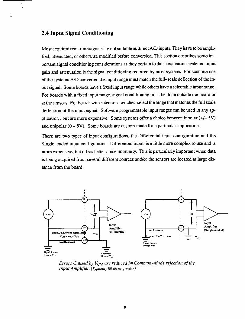
2.4 Input Signal Conditioning
Most acquired real-time signals are not suitable as direct A/D inputs. They have to be ampli-
fied, attenuated, or otherwise modified before conversion. This section describes some im-
portant signal conditioning considerations as they pertain to data acquisition systems. Input
gain and attenuation is the signal conditioning required by most systems. For accurate use
of the systems A/D converter, the input range must match the full-scale deflection of the in-
put signal. Some boards have a fixed input range while others have a selectable input range.
For boards with a fixed input range, signal conditioning must be done outside the board or
at the sensors. For boards with selection switches, select the range that matches the full scale
deflection of the input signal. Software programmable input ranges can be used in any ap-
plication, but are more expensive. Some systems offer a choice between bipolar (+/- 5V)
and unipolar (0 - 5V). Some boards are custom made for a particular application.
There are two types of input configurations, the Differential input configuration and the
Single-ended input configuration. Differential input is a little more complex to use and is
more expensive, but offers better noise immunity. This is particularly important when data
is being acquired from several different sources and/or the sensors are located at large dis-
tance from the board.
I
!
w
Signal So,.n_e Comp,a_
Ground VO1 C_und Vo2
Lead Resistance
V = Vol - VO2
S_nal SoemeGmend Vol
!
I
!
, Es
I _ VG2
Errors Caused by VCM are reduced by Common-Mode rejection of the
Input Amplifier. (Typically 80 db or greater)

2.5 Input Isolation
Input Isolation is essential to protect the computer and expensive hardware from input volt-
age surges that could cause the system damage. High voltage inputs are not always acciden-
tal. For example, a temperature sensor mounted on a motor stator could be at 120VAC al-
though it would not affect the performance of the temperature sensor. Without isolation, the
data acquisition system could be easily destroyed by the AC line voltage. Isolation also elim-
inates the effect of ground loops.
Systems that operate at high gains, are made up of a large number of different sensors/instru-
ments can often be plagued by excessive ground noise. Isolating the data acquisition inputs
from a noisy ground will greatly increase system accuracy.
Isolation can be provided in a number of ways. The most common way of isolating the ana-
log signals is by using a transformer. Optical and capacitive isolators are becoming popular.
Some sensors give the already isolated output and do not require further isolation. Sensors
based on the Hall Effect to measure currents, optical encoders, capacitive encoders are ex-
amples of these. Sometimes, equipment with isolated inputs can cost twice as much as the
non isolated ones, but the added advantages such as long term reliability and accuracy, com-
pensates for the initial cost involved.
2.6 Special Signal Conditioning
Some sensors require special signal-conditioning circuitry. For example, thermocouples re-
quire cold-junction compensation, RTD's and strain gages require excitation circuitry. Care
should be taken that the system selected provides proper inputs and outputs for each applica-
tion. Some data acquisition boards provide these facilities to simplify taking accurate mea-
surements.
2.6.1 Non-A/D Functions
Most Data Acquisition systems require some combination of digital inputs and outputs, ana-
log outputs, counters/timers, motor controllers, etc .... Digital I/O is the most commonly
used non-A/D function. Digital inputs are used to monitor switch closures, sense power
10

on-off conditions, control motor]heaters, activate relays. Position signals from optical en-
coders are also digital inputs. Hence pertaining to the application, selection of A/D boards
should be such that they provide some level of digital I/O capability. For control applica-
tions, along with the digital outputs, the computer should also provide analog outputs. These
outputs are used to generate excitation voltages, control valves, generate waveforms and
simulate outputs from other devices. Boards featuring analog outputs have additional D/A
converters. These unnecessarily elevate the cost if the system application is purely data ac-
quisition and data monitoring. Counting and timing is another data acquisition function. The
timers are used to accurately set sample rates on analog inputs and outputs. They are also
used to measure frequency, count events, measure time and delays and generate known out-
put frequencies.
2.7 Software
Once the hardware is selected, software is necessary to pull the application together. There
are several integrated packages available. One can also write his own program but it is not
recommended as it is a very time consuming process and requires excellent programming
skills. There are some very reasonably priced packages which require little programming.
The software decision will greatly affect the outlook of the overall data acquisition system,
its functionality, and the effort required to get it running. Apart from acquiring and manipu-
lating the data, the user should have other flexibility. The software should be very user-
friendly as most of the time, the person using it may be a non-technical person. Factors to
be considered while making the decision are :
• Capabilities needed : Acquisition, Graphics, Analysis.
• Hardware used : Plug-in, GPIB or RS-232 instruments.
• User interface required: Displays, Automation, Window environment.
• Time and expertise available : Language, Knowledge.
• Cost factor.
1i

2.7.1 Software Selection
Ease of use: Simple systems are intutive, and using them requires minimum study. Systems
that fall in this category are based on interactive state of art user interfaces (i.e. menus or win-
dows). More complex systems are based on programming languages, the most difficult be-
ing assembly language coding for a particular processor.
Adaptability: 'Complex' systems are designed with high priority on a few aspects of data
acquisition and control. For instance, a package can simplify data logging through tightly
defined menus and may even be able to plot real-time graphics. However adding control
tasks and even changing the type of graphics can be difficult. These systems generally have
a predefined model from which they cannot deviate easily. They are limited by their ability
to make descisions and to adapt themselves to a different application. "Flexible" systems
are usually based on some type of programming language and allow the user to make deci-
sions on what the program will do under various conditions. The system can also be altered
to adapt to changing requirements. A package offering optimum compromise between flexi-
bility, performance and ease of use, is the best choice.
simple applica-
u or °rti°n n°vic ....................,[ ASYST [ write it yourselfLabtech Note-
book I I
Easyest LX VIEWDAC DriversLabView
Asystant GPIB
complex
applications
or experienced
users
Processing speed: This is a critical consideration for real-time systems. How fast can the
system acquire and store data? How fast can the system analyze data? How fast can the sys-
tem display data? (i.e. can it do real-time graphics or only post acquisition display of
data? ) Can this system perform control functions (can it make decisions in real-time and
how powerful is the decision making capability?). 'Slow' systems are generally useful for
slower decision making or control application.
12

Thesethreefactors,defineaspectrumwith simplesystemsatoneendandcomplexsystems
ontheother.Thechartaboveshowsthespecmamandplacessomeofthecommerciallyavail-
ablesoftwarepackages.Theplacementof thesepackagesonthediagramisbasedoncaches
generallyacceptedstrongpoin.ts.Tochooseasoftware,determinewheretheapplicationlies
alongthesoftwareselectionspectrum,thetimespentin troubleshootingtheapplicationsand
future applicationneeds.
Thenafterreferenceto detailedsoftwaredescription,makethesoftwareselection.Theven-
dorsuppliedspecificationsof someof thepopulardataacquisitionpackagesareattached.
Thesesoftwarealsomentiontheboardsthattheyarecompatiblewith.Thismakestheselec-
tionprocedurea lot easierfor thesystemdesigner.
With thesebasics,it is a straightforwardprocesseasyto designadataacquisitionsystem
to matchone'sneedandbudget.Theprojectdiscussedin thesereportputsthesethings to-
gether to design a data acquisition system for a A Welding Robot.
2.8 Computer Considerations
IBM PC/XT and IBM PC/AT and compatibles are by far the most popular host computers
for data acquisition. PC/AT bus is referred to as ISA (Industrial Standard Architecture) bus.
The PC/XT bus performs bit data transfer and is capable for transfer upto 100K words (16
bits) per second. The ISA bus performs 16-bit transfers and can perform upto 300K transfers
per second. Boards with on-board memory offer 1M samples/see or greater even in PC/XT
bus computers.
Several data acquisition products are available for IBM PS/2 (Micro Channel) computers
and compatibles. In general, the data acquisition products donot require powerful comput-
ers. However when combined with analysis and graphical display, powerful computers
(80386 and 80486) are strongly recommended. Often the softwares selected for application
will dictate the type of computer to use. For example, extremely powerful VIEWDAC pack-
age requires atleast a 386 with 6 MBytes of memory and a 387 coprocessor).
13

Standard PCs may not be suitable for certain industrial or harsh lab environments, due to
factors such as heat, shock, electrical noise, vibrations. To deal with such environments,
many manufactures are producing rugged PCs for the market. Some of this PCs use standard
motherboard with expansion slots, and many others use passive backplane. A passive back-
plane is the backbone of many industrial computer bus systems (such as VME and STDBus)
as well as many mainframe computers and early microcomputers. It is simply an array of
connectors wired together to form a bus, without any active circuitry present. The CPU is
on card, plugged into the bus. This adds extreme flexibility since upgrading to another pro-
cessor simply involves switching the CPU card. This also guarantees all signals required
by the CPU are present on the passive backplane, adding flexibility for having multi-proces-
sors. The major disadvantage for this approach is the added cost involved.
A continuing problem in the area of industrial PC systems is how to enhance the ISA standard
while maintaining compatibility with products from different manufacturers. A new stan-
dard called PCXI from Rapid Systems is a potential solution. It is intended for multivendor
standard for data acquisition and industrial instrumentation systems. It incorporates a stan-
dard a standard ISA passive backplane and power supply into a modified PC chassis. PCXI
is PC equivalent to VMXI, the VME bus instrumentation. It supports several manufactures
and will probably become established as a true standard.
2.8.1 The VXIbus
The VXIbus is a fast growing platform for instrumentation systems. It was introduced in '87
and has become very popular since then. VXI is based on worldwide VMEbus standards and
so VME modules can be used in VXI systems. The VXI backplane includes a 32-bit VME
computer bus as well as high performance insmamentation buses for precision timing and
synchronization between instrument components. VXI benefits user in following the ways:
• Increased system throughput
• Smaller size and higher density
• Reduced cost
• More precise timing and synchronization
• Standardized, multivendor protocol for systems configuration and pro
gramming
14
DataacquisitionandcontrolsystemsbasedontheVMEbushavelongbeenpopularin indus-
trial researchenvironments.WithVXI, wecanuseexistingVME modulesandalsoenhance
VME to improveperformanceandreliability. VXI's packaginghandlesvery highdensity
in a singlemoduleandthereforevery attractivefor applicationswith high channelcounts.
A varietyof self-processingmodules,includingdigital signalprocessing(DSP),areavail-
ablewith VXI andVME. With VXI's multiprocessingarchitecture,high datatransferrates
andshared-memorycapability,we canprocessmultiplechannelsof acquireddatacanbe
processedin realtime.
2.8.2Plug-in boards Versus external Systems
Data acquisition systems can be classified in two basic types. The plug-in boards where the
data acquisition boards plug directly into the computer, and the external systems where the
whole data acquisition system is mounted outside the computer on an external chassis and
is connected to the computer through some type of communication interface (e.g. RS-232
, RS-422, IEEE 488 ). Depending upon the application, one or the other or sometimes both
(hybrid systems ) are selected to best match the application. The following table describes
the features of both systems:
External systems also have several advantages. Since they are not tied to a specific computer
bus, they can be used by "closed architecture" computer that have no usable slots. External
systems are preferred when number of I/O channels are more than 50 - 100 since it is very
difficult to physically connect large number of wires to a personal computer. Their enclosure
and their power supply are specifically designed for data acquisition applications. This re-
suits in more accurate measurements at high speeds.
As the plug-in boards plug directly in the computer, use its power supply and also does not
require an external chassis, they are less expensive. Also, as they plug directly into comput-
ers bus, they have ability to transfer data directly into host computers memory at full bus
speeds. Though external systems have ability to acquire data in local memory at high speeds,
15

FACTOR PLUG-IN BOARDS EXTERNAL CHASSIS
Cost Low Moderate
Expandability To 100 Channels Almost Unlimited
Portability bet.
Computers
Only with Compatible
Slots
Bus independent
Data Transfer
to Computer
memory
Full computer Bus
Bandwidth
Usually less than
60 - 70 KHz
the actual transfer of data to computer is limited by the communication link. Also where
space is the restriction, plug-in boards are ideal choice. There are wide range of data acquisi-
tion boards available by various manufacturers. These boards are designed to be good for
a particular application. They all vary in their specifications as shown in the attached data
sheets. Based on ones need, selection of the data acquisition board and the relevant software
has to be done as described above.
After the data sheets, we will briefly explain why we opted for CIO-AD 16Jr and Driver-
LINX combination for the project.
16

DM pg/x'r/AT ANALOG&mmTAL_ 60A_
ANALOGINPUTS _.
RO._,OMPUTER CHAIIIIEU
MAX INPUTSAMPLE(S/Si RANGE RANGE
BITS GATE (VOLTS1 SELECTION
ANALOG OUTPUTS _ DIGITAL I/0
IHPUTE/' PACERCHANNELSRESOLUTION OUTPUTS CLGCX
COUI11HS'TIMEN$ PAGE
DAS-1402 ;C,_TIAT
DA$'1_1 =_,,'XT/AT
OAS-1NG2
I2.8ff RE3"DLLn70#
:..'E/AT 8 SE 12 ! M =10.:L:5,+2.5 Software -- --
• 10.+5
OAS-5O ":.rXT/AT 4 SE t2 I!,4 :10,+5.+_2.5 Software --
+10,+5
0AS_I AT0nly 16 SE/8 Diff i2 45 K :!0, +1,:t0.1._+0.02 %ffvme 2
.10, +1,+O,1,+0.02V
0AS-4062 ,_TOnly 16SE/8 Dif !2 250 K :t0. :t:5,+2.5.:tl.25 .;oftware 2
+10,+5,+2.5. +125 V
OAS-L_ ;UXT/AT 16SE/8 Dif !2 1001( :10. _. :t:0.5._.05 5offware 2
+t0, +I, +0.1_.I V
)AS-1501 ,_C,,XT/AT 16SF..J8 Diff [2 100K :10, -+1,_.1. _.02 Software 2 12
........ +I0,_ I. +0.1.+0.02V
0kS-1602 _,XT/AT 16SFJ8 Dif 12 _OOK :10, :iS,+_2.5._+1.25 Software 2 12
_10,+5.+2.5.+1.25V
OAS-15F ::(T/AT t6 SE./8Dif _2 ;00K _-!0._, +2.5.+125 .Lvitches -_ ;2
,I0. +5.+2.5.+}25 V
16SFJ'8 Dif :2 '.C0K :!0._+I. -K).I, _.02 -:offv,rare -- --
........ _._;o.ti=_.L__02v!6 SE/8 Dif _2 100K :_0, _. :b?..5,.*_t.25 Software -- --
+10.+5,+2.5.+125V
16SE/8 Dif 12 70K :I0,±1, _.1, __.02 Software 2 ]2
FC/XT/AT 16SFJ8 Dif
DAS-1N _eC_IAT 16 SE/8 Dif
0 29
_ _ y
12 3 out,8in Y
I2 3out.8in Y
!2 _ out, 8 in Y
+10, +1.+0.1.+0.02V
t2 70K :10, :1:5,:F.2.5.±t.25 Software 2 12
........... _,I0. +5._2.5._1.25 V ..........
_2 50 K _t0, :1:5,-+2.5,+1.25 Switches 2 12
+10,+5, +2.5,+1.25V
12 4 K it0, :t:5,:LO.5.:_._.-Xl.01 Software -- --
........ +i_o,.+j,_J._+O:O2_v.............12 4 K --I0._, -+0.5,:tO.05._.0I Software -- --
,I0.+1.+0.1.+0.02
t2 _K -5 ._x_ -- --
_2 :OK :10, _+1,_0.1,_).02 _-oftware 2 ;2
+10. +1.+O.1.+O.02V
12 4K tlO. +5,_.5, tO.05 Software -- --
........ _.o_.+m.ft. to:1,_:_y_ _.
I6 476 K t10, _. -+2.5._+1.25 Software 2 16
+!o.+5_.Gs,+i_25_v ............6 _6 t5. :LO.5._.05 Software -- --
-+3.27._.327. _.0327
15 __:5_ __._,_.+_2.__.2So_r_re _-__ -14 350 ,10. +5,+2. +1 Software -- --
13 ;0 *-.2_047 Switches 2 12
32 Y
32 Y
0 33
0 37
0 37
2 41
47
47
J in.4ouI Y
Jin. 4OUt Y
4in 4out Y
4 in,4 out Y
4 in.4 out Y
55
51
51
Y 514in. 4out
4 out.3 in
4 out.3 in
4 out.3in Y
4 in.4out v
3in.4 Out v
I)A,_VAO ;C,0('r/AT 8 Diff or SE Y 3 58
DA,S._A =C,XT/AT B Diff of SE Y 3 58
nAS-ILT "XTIAT 8 SE 3 81
;,'.croChannel 16SFJ_Oiff I 134
MicroChannel 3 Diff 3 140
mB
Ok,_I_ES PC,_T/AT 8 Diff 3 out.8 in Y I 64
AOC-15 -_C/xr/AT 8 Diff 5out. 2 in Y 0 67
_'_--OM._.?C,_/A]__ 1 ,_ o 2+,+CHRO__IAj Pc,_r/AT ....... 2 SE 4 in, 4out _+ 0 77
D_CON-1 ;C,XT ,,tDiff 12I/0 ,,_ 0 70
PCIP-?,C:_'EPC,XTIAT 2 Diff 8 :0 M _0. to:t0.02 Software -- -- -- Y 0 218
_ _ _ ;rlI0 r3n_l_
OAS-TEMP :C,XTIAT 32 01 ° 200 -25 1o+105=C Software -- -- -- N 0 79
GAS-4 ;Q'XT/AT BSE ,:] S?,VLimffed _ FTxed -- -- Jout. 3 in 'J 0 62
AT'CODAS :_7Only 16SE/8 Diff :2 _,0K -S,+_2.5._+1,_.5 Software _ 12 3in.8 out Y 0 74
MCA.COOA$_ MicroChannel 16SFE8Diff ,2 50]( _. +_2.5._-t. -'-_ Soflvrare ! 12 9in.8 out Y 0 137
r
h'eitklev MetraHyte 440 Myl_ Standit_ Blvd.. Taunton. MA 02780 (5(/8) P,.-_O-,?O00 25

ORiC_AL PP.OE tSOF pOOR QUALITY

x,
SELECTINGTHERIGHTSOFTWAREI
In order to determine which package is best for you, it
is necessary, to review your data acquisition system
needs.
Acquisition What capabilities wiil be used?
•Mo, D/A. Digital I/O?
• GPIB or RS-232 instruments?
• Numbers oi Channels?
, Maximum number of samples required?
. Maximum sample rate?
Analysis/Graphics What will you be doing with the
data? Will the data be sent to another packagefor anal-
ysis? What formats are required? Will it be useful to
analyze and plot the data where it is collected? Built-in
analysis and qraphics can provide rapid insight into
results as the data is collected. ,_e hard copy graphics
required? Do you need to incorporate custom routines?
Do you want to generate custom graphics or reports?
User Interface Who will be using the s.vstem? The
software is the interface m the system, if the system is
to be used by inexperenced operators, it must be easy
to use. Automation can help reduce operator errors. A
menu driven interface can be used to guide the selec-
tions and save on repetitive tasks. A custom control
panel can be the easiest interface of all.
Once you've answered these questions, the fol-
lowing software feature guide will help in choosing the
most appropriate package for your application.
The hardware compatibility, chart lists the boards
and accessories supported by each software package.
\Ve are constantly adding new products and capabilities
:o this list. so please cail if your board isn't supported.
SOFTWAREFEATURESELECTIONGUIDEI
EASYESTLX
IIII III
EASYEST LABTECH Snap- ControlAG NOTEBOOK Master EGFeatu_ ':|_VDAC A£Y':.T
ComputerRequirements 386/4_ PCXT/AT PC.'if/AT PC.'if/AT PCx'r/AT ,PCW/AT FCX'T/ATwl copr. '_'Icope. ',vlCOla'. v/cop-. _vt'41_ P,AM wi 512_ RAM
&6 MBRAM & LMBRAM &2 MBP,._,I &2 MBRAM
OperatingEnvironment DOS DOS DOS DOS DOS/ ?,'indom DOS
Max.MD (D/A)Channels :_ ]oos 16o t6o 256/16 _ame 236asboard
Max.MD Boards 20 lO 10 t0 16 8 3plus F-Ws
Max.AcquisitionStk*ed '.lax HW Uax.HW ),tax l-fi_" )lax.ItW Mxx.l-lW ?,IaxIt'W 10I, Opoimsper sec
Createmacros, Yes Yes Yes Xo Yes Yes Sosequences,[email protected]
Callsm standard Yes Yes No No No No No
pmWamminglanguages
integratedAnalysis Excellent Excellent Good - - Excellent Good
Max.P,eal.time ManyI Manyi 8 8 50 I00 _6
displa5channels
Integratedfyaphics Excellent Excellent Good C_ood 6ood Excellent _,'_,,-y.Good
CustomUser Yes Yes Yes No _5mited Yes NoInterface
Graphicout0utto Yes Yes Yes Yes k'es Yes _mited
printers&plotters
_232 &GPIBsu@on Yes Yes .'40 .% }es Yes \o
Page Number 162 I68 164 166 :70 172 !74
I Umited by screen resolution only.
I
160 _'992Keithley MetraBNe Data Acoumrion Catalo¢
O.RI_NAL FAOZ 15OF pOOR QOALITY

HARDWARE/SOFTWARECOMPATIBILITYCHART
EASYESl' EASYEST ¢onbroi Snap LabtodVIEWDAC LX AG ASYS"T EG Master _011300K
ADC-16 C C C C
CHROM-IAT Y
CTM-FER
CTMO5 Y Y
DAC@2 Y Y
DAS-16tF/G Y Y Y* Y Y Y Y
DAS-1600/1400 C C C* C C C C
DAS-20 Y Y Y Y Y Y
DAS4 Y Y
DAS40 Y Y Y Y Y
DAS-50 Y Y Y Y Y
DAS-Sg/SSH-SS C C C C
DAS-81PGAILT "i" Y Y" Y Y Y Y
DAS4AO C C C C
DAS-RRF£ Y Y Y Y Y Y
DDA-06 Y Y Y Y Y Y
EXP-16 C C C C Y Y
120'.m C C C C Y Y
EXP-GP C C C Y
ISO-4 Y
KI:'G488.2 C C Y Y
KPC-4882AT C C Y Y
KI_488.2 C C Y Y
MB4)I & MB02 C C C C Y
PD[SO.-8 Y
PDMA-16/32 Y
PIOII2124/HV Y Y
SSH4 C C C
_tCCTM-05 Y Y
)ICDAS-16G Y Y Y Y Y Y
_CDAS-8PC,A Y Y Y Y Y Y
pCDDA-04 Y Y Y Y Y Y
t_CPDISO-8 Y
pCPDMA-32
pCPIO-12124/72 Y Y Y Y Y
500A Y Y Y Y Y
575 Y Y Y Y Y
576 Y Y Y
Y = Product is supponedC = Call for details
* = Start-up manual available
qo_4,_ 18•,.,uam KeithleyMetraBWe 440 Myles Standish Bh'd_. Tauntott, MA 02780 (508) 880-3000 " t_t-_

4; )ME A effware escdptionz equirements
Labtech®Notebook
Real-Time Access TM
$995 OM-700, OM-900, OM-1050,UCDAS-8-PGA, WB-800/815/802/817/820, DAS-8/16/20,PIO-12/24, CTM-05, DDA-06,DAC-02, CHROM-1, WB-AAI/FAI/ASC/AVO,OM-480/481(*See IxJ.B-5 for add'l, hardware)
$295 Requires Labtech Notebook
General Purpose LaboratoryData Acquisition,Control andAnalysisSoftware
Labtech NotebookAccessory Program
SWD-LTN
SWD-RTA
Labtech Chrom $495 No Hardware Supplied Chromatography Analysis SWD-LTC
CHROM + _ $645 Same as Acquire Chromatography Analysis SWD-LTP
WorkBench PCTM
SnapMaster
IoCalc
Easyest LX
Unkelscope TM
$995
$995
$550
WB-AAIIASC/AVOIDIOIFAI ,OMB-PER-488, DAS-8E,AS-1Cv'16F -
CIO-AD16/16F, CIO-AD16JR,CTM-05, DAS-8PGA, DAS-16/
16F/16G, DAS-50, DAS-HRES,PCL-718, PCL-818,UCDAS-8PGA
DAS-16/16F, PC-30, PC-60,PC-61, PC-6& OM-272, DP41,CDP-75, PHI-40/45
$99-_ I DAS-8/8 PGA, UCDAS-8PGA,--- i DAS-16/16F/16G, UCDAS-16G,
DAS-20, DAS-50, CTM-05,UCCTM-05, PDMA-16,W B-800, WB-815, WB-820
iFrom !WB-800/815, DAS-8/16/16F,$349
$495
WBIAAIIASCIFAI
iWB-800, DAS-8/16/16W16G,DAS8
$990 f DAS-8, DAS-16, WB-800
It
$495 !No Hardware Supported
$3995 Same as Labtech Notebook,
does not support OM-480_Series
Snapshot TM
Snapshot withSnap-Calc TM
Icon-Based Data Acquisitionand Control Software
Data Acquistion, Analysis andDisplay Software
Real-Time Spreadsheet forDOS and OS12
Data Acquisition. Analysis andGraphics Software
High Speed Data AcquisitionSoftware
Storage Oscilliscope EmulatorSoftware
Mathematical Analysis forSnapshot
Frequency Analysis forSnapshot
industrial Monitoring andControl Software
Snap-FFT TM
LTlControF"
SWD-WBP
SWD-SNMA
S'WD-IOCA
SWD-EZU
SWD-US
SWD-SN5
SWD-SN£
SWD-SNF
SWD-LCT
PRECEDING PhGE _LANK NOT FILMEb
B-3

_-21
I
PC-Expert
SlideWritePlus_=
STREAMER
ControlEGT=
I_iSP _
L_"
P_jramming Tools
TechGraphPadm
_Wus Plus
$225O
S445
$27S
$195
$5OO
From$oos
Ssss
$200
$395
$1OO
S350
$25
$25
$349
DAS-8,DAS-16/16F/16G,DAS-20,WB.800/802/815/817/820,OMEGAWorkhorse,OM-1050
NoHardwareSupported
DAS.16/16F/16G,DAS-20,PDMA-16,PDMA-32,DAS.HRES,UCDAS-16G
,, ,,
iDAS-16/16F,CHROM-1,WB-800,WB-AAI/FAI/ASC
IWB-800/815/802/817/820
JNoHardwareSupported
NoHardwareSupported
NoHardwareSupported
No HardwareSupported
No HardwareSupported
No HardwareSupported
No Hardware Supported
No Hardware Supported
No Hardware Supported
High-SpeedData,,_:quis_onSoftware.IndustrtaJMonitoringandControlSoftware
PresentationGraphicsforScientistsandEngineers
High-SpeedDiskStreamingSoftware
EconomicaJDataAccluisitionSoftware
DataAcquisitionand Control
DataAnalysisSoftware
StatisticalOuaJityandControlChartingand Analysis
Real-TimeGraphics,Measurementand ControlTools
DataPlottingSoftware
VirusProtectionSoftware
Graphicsand AnalysisSoftware
Atomic Reference Database
Unear ConversionFactors
Mathematical Equation Solving
iEGAMAC_ 232 $595
_ Bench Mac $995
Most RS-232/422.Instruments
WB-FAI SE or M2, WB-AAI SEor M2, OMB-MAC2-488
Macintosh Data AcquisitionSoftware for RS-232/422Instruments
Icon-Driven Data Acquisitionand Control
SWD-IPC
SWP-SLP B-25
STREAMER B-26
SWD-LAC 8-27
SWC.CED B-28
SWD-DSP B-29
SWA-NWA B-31
SWV-tPC B-32
SWP-TGP B-33
SWU-ANTI B-34
SWP-PLT B-35
SWU-ATM B-32
SWU-UNT B-32
SWE-MCD B-37
SWD-MAC232 B-38
SWD-WBM-2 B-39
B4
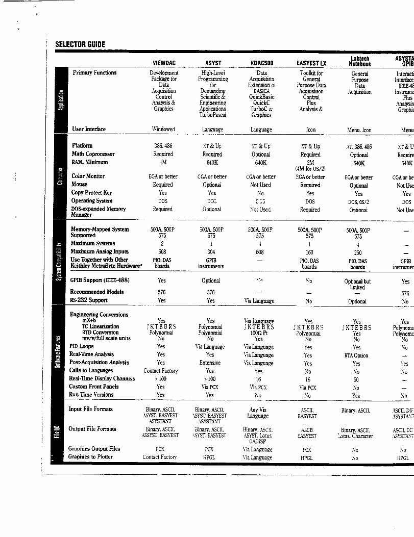
SELECTORGUIDE
VIEWDAC ASYST KDACSO0 EASYESTLXLabtech
Notebook
Primary. Funcdons DevelopmentPackage for
DataAcquisition
ControlAnalysis&Graphics
High-LeveiProgramming,
IOg
DemandingScientific&Engineerin_ApplicationsTurboPascai
DataAcquisitionExtensionot
BASICAOuickBasic
OuickCTurboC&Graphics
UserInterface Windowed Language Language
ToolkitforGeneral
Purpose DataAcquisitionControlP]us
Malysis &
[con
GeneratPurpose
Data.Acquisition
Menu.Icon
Platform 386.486
Math Coprocessor Required
RAM.Minimum 4M
ColorMonitor EGAorbetter
Mouse Required
CopyProtectKey Yes
OperatingSystem DOS
DOS-expandedMemory. Requiredmaimer
.W&Up
Required
640K
CGAor better
Opdonal
Yes
DOS
Optional
X'T&Up
Optional
640K
CGAor better
Not Used
No
2L3
NotUsed
X'T& Up
Required
2M(4MforOS/2)
EGAorbetter
Required
Yes
DOS
Required
AT,388.488
Optional
640K
EGAor better
OptionalYes
DOS. 0S/2
Optional
Memory-MappedSystem 50(0 500P S00A.500P 500A.500P 500A.500PSupported 575 575 575 575
lt_dmum Sysmms 2 i 4 I
Maximum AnalogInputs 608 304 608 160
UseTogetherwithOther PIO.DAS GPIB -- PIO.DASKeithleyMetraByteHardware" boards instruments boards
500A.500P575
4
250
PIO.DASboards
ASYb'WAGPIB
[nteraclJInterlace
[EEE4_lnstrume
PlusAnalysisGraphi(
Menu
k'I'& U
Require640K
CGAor be
NotUse
Yes
DOS
Not Use
w
q
GPIBinstrumen
GPIBSupport(lEEE-488) Yes Optionzd v? "b Optionalbut Yeslimited
Recommended Models 576 576 -- -- -- 576
RS-232 Support Yes Yes ViaLanguage No Optional No
Engineering ConversionsmX+b Yes Yes ViaLanguage Yes Yes YesTC Lineatizadon JKTEBRS Polynonuai JKTEBRS JKTEBRS JKTEBRS Polynonu:Irrl)Conversion Polynomial Po.lynomiai 100flPt Polynormai Yes Polynotm:mv/vtfuU scaleunits No No Yes No No No
PIDLoops Yes _laLanguage _laLanguage Yes Yes So
Real-TuneAnalys.is Yes Yes Vh Language Yes ETAOption --Post-Acquisition Analysis Yes Extensive ViaLanguage Yes Yes Yes
Calls toLangtmges Contact Factory. Yes Yes No No So
Real-TuneDisplay Channels > 100 > 100 16 16 50 --Custom Front Panels Yes ViaPCX ViaPCX ViaPCX No --
Run TuneVersions Yes Yes No No Yes No
Binary.ASCII._SYST.EASYEST
,ASYSTANT
Binary,ASCII.:,SYST.L_S_T_,ST
Binary..ASctLASYST,Lotus
DADiSP
ViaI.anguage
_,qaIanguage
Binary.ASCII.
Binary..ASCIi.Lotus.Character
No
No
Input File Formats
Output File Formats
GraphicsOutputFiles
Graphicsm Plotter
Binary,.ASCII.,_YST,EASYEST
ASYSTANT
Binary.,ASCII..Z%YST.EASYEST
POX
Contact Factorypcx
HPGL

CALLDRIVER INTERFACE
The standard Call Driver is designed to be used from
interpreted BASIC,Compiled BASICor QUICKBASIC.The calls are a collection of functions that are accessed
from a BASICpmgrmn,each througha singJe line Callstatement. The various modes of the call routine select
all of the functions of each board, format and error
check data and perform ffequen@ used sequences of
instructions. To use the Call commands, simply select
the applicable call routine and pass the appropriate
parameters. The driver handIes all lowlevel hardware
manipulation. A consistent set of defined call command
names are used in the new DASdrivers so you can
write board-independent programs and easily change
from one board to another. The Callcommands allow a
great deal of flexibility,and allow background data
acquisition. Most commands execute faster using the
Call Driver versus the File I/O Driver. Many of
Keithley MetraByte's data acquisition boards have
optional Pascal, Cand Fortran tPCF) interfaces withsimilar functionality. Some of the n_oresimple hoardz
include the PCFcapability in the price of the standard
board.
The followingexample shows the CallDriver
interface using the BASIClanguage. This program per-
forms an analog to digital conversion on channel 4 ofthe ADC-16.
10 ' Configure ano m4tiafize
the AOC16
20 CALL,_C16DevOoenlFilename$. NumOfgoards%.ErrFtag%)
30 iF ErrFlag% < • 0 THEN STOP Stop if Configuration Error
40 Start%. 4 ' Sel up channei number
50 Gain% • 0 ' Set up gain
60 CALL KAO(Start%. Gain%. ErrFlag%) ' Get a reading
70 IF ErrFlag% < • 0 then PRINT
"AO Error Occurreif"
CallDriverinterfacegivesIhehighestpedonnance.
WINDOWS 3.0 DLL INTERFACE
Micmsoti Windows Dynamic Link Libraries or DLL
standardallows you to use any language that supports
the DLLconstruct, including Microsoffs Visual Basicand C for Windows and Borland's C++and Turbo
Pascal for Windows. Using the DLLdriver option, allthe features of Microsoft Windows are accessible. This
includes running multiple programs and using extend-
ed memory, all through the consistent graphical user
interface of Wmdows. Microsoft W'mdowslets you set
up and run your data acquisition programand automat-
icalty transfercollected data to another applicationthrough the standard Dynamic DataExchange (DDE).
A typical example is collecting temperature mea-
surements with an ADC-16and transferring the data toa spreadsheet package, such as Excel, for automatic
scaling and plotting. Allfeaturesand commands avail-
able in the Call Driver interface are accessible in the
DLLinterface. The same command set is used forboth
DOS and W'mdowsbasedprogramming.W'mdowsalso
givesaccesstonew languagessuchasVisualBasic.A
VisualBasicexampleisinchdedwiththeDLLInter-
facetoshowhow easyitistosetupacontrolpanelfor
yourDASboardandtoacquireandgraphdata.
TheDAS-1600andVisual6asicmal(ecreatingcustominter-facessimple
0 _ 7_ v t992 KeithleyMetraByteDataAcquisitionCatalo_anaReterenceGutde

DIRECT REGISTERI/0I
,.-hedirect register I/O programming should be used
nlyifyouhaveahighlevelofprogrammingexpertise
,_dunderstandingofyourPC'sarchitectureandthe
?O'sPeripheralControllers(the8259Interrupt
Controller,the8237DMA Controller)orifyouarepro-
grammingaverysimpleboardsuchastheP[O-12digi-
talI/Ointerface.Thismethodcanbeusedwithmost
languages,DirectRegisterI/Ohastheadvantageof
beingthefastestmethodtocommunicatewiththe
board.A disadvantagewithprogramminginBASICis
thatBASIChasnoInterruptorDMA processingfunc-
tions,sobackgrounddataacquisitionisnotavalhble
whenusingthismethod.Ourusermanualsprovidethe
details needed for implementing register program-
ruing. This can be used with opera_g systems, such
as UNIX,that are not presently supported by ourdrivers.
The Driver Table to the right illustrates driver
support for our data acquisition boards. A PCFpackageincludes Pasc_ C and Fortran Call drivers and a user
manual for the supported board. The Advanced
Software Option fora board includes the File I/0
Driver, Pascal and C CallDrivels, U,e ,Vmuows J.u
DIL,comprehensive user manuals and examples.
Programming Tools help create custom graphics.
DRIVER AND UTILITY SUPPORT
POP FILE Basic Register PCFUP ]/0 Call DLL i/0 STREAMER Calls
ADC-16 _ "_'* _ ".'* 4 _'*
CHROM-IAT ,, ,,'
CTM-PER -, ,;
CTM-05 '_ _ _.
DAC-02 ,J
DAS-16O0/1400 ", _" ', i' ,, _, -'-
DAS-20 _ _ _
DAS-4 _ "_
DAS-40 ,. _ \
DAS-50 ", ,." _. ,' -, x -
DAS-58 _ _'" _ v'" ,_ ",*
DAS-811_AJLT ', ",D "_
DAS-8/AO ", 4D _ _r
DAS-HRES _, ,,' _,. _,
DDA_
KFC-488.2 ',' ";' ",/ V
KPC-488.2AT -_ ",,: q q
KPS48&2 "# ,, ,,' \,
PClPFam_y 4 ,,'
PDISO-8 v
PDMA-16/32 ", _ _ -,
PIO-12124/Hv
_CCI'M-O5 -,
,aCDAS-16G , ,, ,,- ;
uCDAS.-8PGA ,.
uCDDA-04 :
uCPDISO-8
_CPDMA-32
\
aCPIO-12/24/72 ,,
= PartofAdvancedSolh_areOption
,_ D = DdverLZNXsu_'_
= - lfusedasaDAs-16
• .Ucs'rREAMER
" tt_3Keithley MetraBvre 440 Miles Standish Blvd.. Taunton, MA 02780 _508) 880-,?000

3.0 Data Acquisition System Hardware
, :+.........,.....,.,
.:;.:;4!!:===i_iiii_iiiiilii!i:=_,i_,iiiii_iii_=;:=/di=__._._!_',!.i..:======================================================================================_j":: ::::
_:::_es.'..'._,::,_i:__:_ _ Why we selected::-:r_,......._.*..__ _-::_ ClO-AO16Jr and
":$_: .._.:%i:i:i:i:i:':_:::.:: ,-!:_.
.,,..._N_i_;_ii_ii___ __ DriverLINX,:,_..,,,_ ............_w,_ comb�nation::::::_¢::_.1_ !::;::::::::___': _,_
•...:. ,..., _ .@ .>:.:: • . ..:.:._:.:.:.:,:.:-:.:.:.:.,_
........ ".............::::;i_:i...... ,_:_;_ii!ili:;.-:'_..L_,."i_iiii!ii_.",:> ....::i:_8:: ...:,:.::::::,:_,?i:':::':_:_::_.8::'&.':i:,_
....::.. ':81: _.-....-" ,_-_.!:_._-_i_.:i.%!:_:i:_:.:.!_.j$i:i:i:i:i:._
,............ _.t_.:._:._:_,..:.:.:.:,..:._.............................. ""._i:............_. .!__t:':_i_i..1@'.-'}i_gi:;_.......: _:_ _"".... ::i:_(':_:_i-!8K':!_:i:i:i:i:.::!:!Si:!:i:i:i:iii____'_ "._':::!_!".:!!_i!_!_i_i!i_!!i!!_!_!_ff:::_i_::!i_::_!!!!!::!!_i
.,.,:.............................._.._._:....,....,--,::.:_:.,:£,-.,::.:.::.,,.:::,_...¢,.,
To design a Data Acquisition System for a welding Robot. Signals from various sensors of the robot
are acquired and after proper signal--conditioning and isolation (if required) are fed to the data ac-
quisition card. There are basically three types of input signals, analog signals, digital signals and
the counter-timer signals. The analog signals are digitized after proper conditioning to take full ad-
vantage of the input range. The digital signals are raised to TTL levels and fed to the digital I/0 port
of the Data Acquisition card. Based on the selection criterion as described above, a device driver
is selected (DriverLINX) to communicate with the Data Acquisition Board (CIO AD-16). Program-
ming for the Driver and the File I/0 command interface is done in Visual Basic. Acquired data can
be stored to a file in binary or ASCII format for importing into commercial and custom analysis pack-
ages. The analysis package is also programmed in the Windows environment using Visual Basic.
3.1 Sensors/Signals
Data Sensor Signal
Position Optical Encoders Digital Pulses
Arc Current Hall-effect 4 - 20 mA
Arc Voltage Circuit Voltage
Wire-feed Encoders Digital
P:_E_EDING PPlGE BLANK I']OT FILMED

These are tentative signals on the basis of which, the data acquisition card is se-
lected.
3.2 The Data Acquisition Card
CIO-AD16 is multifunction analog and digital I/O board. It is small in size, acquires
data very fast ( 110 KHz for CIO-AD16Jr and 330KHz for CIO-AD16Jr - AT). It is
a plug-in data acquisition board and can be installed on any IBM PC/AT or compat-
ible. It can turn the personal computer into high-speed data acquisition system.
CIO-SSH16 is a 16-channel simultaneous sample and hold accessory board, it
acts as a front-end signal amplification and capture for CIO-AD16 series of analog
input boards. This board provides two major functions. Sixteen differential amplifi-
ers have individualswitch selectable gains of 1, 10, 100, 200, 300, 500, 600, 700,
and 800 providing very flexible amplification for individual signals. After amplifica-
tion, each channel has a sample and hold which is controlled by the CIO-AD analog
input board. In applications where, a number of signals must be analyzed and
compared, such as high speed transient analysis and spectrum analysis, a channel
to channel skew may be unacceptable. The CIO-SSH 16 eliminates the channel to
channel skew associated with multiplexed A/D inputs. The data sheets for CIO-
AD16 and CIO-SSH16 are attached.
3.3 Software
There are various software packages available for data acquisition, analysis and
display. These packages are very expensive depending on various features it offers.
Most of the features are extra for a specific application and still may not be to the
complete satisfaction of the user. For a specific application, it is best to design a
custom-made software which exactly meets the requirements. To help us commu-
nicate with the data acquisition boards at high level, we use Drivers. This saves us
the trouble of writing directly on board registers.
For our application, we use windows 3.0 Dynamic Link Libraries (DLL) interface.
Microsoft Windows DLL standard allows the use of any languages that supports DLL
construct. For our application, we use Microsoft's Visual Basic. Using the DLL driver
26

option, all features of MicrosoftWindows are accessible. This includes running mul-
tiple programs and usingextended memory all through the consistent graphical user
interface of Windows. Microsoft Windows gives us flexibility and lets us set up and
run the data acquisition program and automatically transfers collected data to
another application through the standard Dynamic Data Exchanga (DDE).
For our application, we are using DriverLINX as our Driver. It has following features:
• Language Independent dynamic link libraries (DLLs).
• Multitasking and multiuser capabilities.
• More than 70 high level functions supported.
• Allows maximum data acquisition speeds.
• Comprehensive on-line help.
DriverLINX allows us to use CIO-AD16Jr with MS Windows 3.0 environment. It pro-
vides us high-level interface with data acquisition board. This driver contains all the
intelligence necessary to to manage the details of data acquisition tasks, insulating
the developers program from hardware and implementation strategy. Applications
communicate with DriverLINX by passing a"service request" that contains the spec-
ifications for the data acquisition task.
DriverLINX supports all functions of CIO-AD16Jr including analog input and output,
triggering, gain setting and DMA transfers. It can support upto 6 boards and 10 con-
current tasks. Special version of DriverLINX(DriverLINXVB) is available to program
in Visual Basic.
2?

4.0 The Data Acquisition System Software
This software incorporates window programming techniques and operates in Micro-
soft's Windows 3.0 environment. DOS programs are written sequentially, i.e. one
event follows the other. In DOS programs, controls goes down the list of statements,
more or less the order which the programmer designed. However, windows is differ-
ent.
An application under Windows typically present all possible options ( in the form of
visual objects) on the screen for the user to select for themselves. In this way, it rep-
resents entirely new kind of programming -- event-Driven, and object-oriented
programming. That is to say that, a programmer is no longer completely responsible
for the flow of program. Rather the user is. The user selects among all the options
present to them, and it is upto the program to respond to them. The code is specifi-
cally designed to respond to a particular event called-on by the user. Our program
will typically be the collection of code sections like this, one after the other. That is
how event driven program works. Besides being event driven, window program-
ming is also object-oriented. That is easy enough to see on screen: Just pick up
an object or a paint brush on the screen and move it around. This corresponds close-
ly to what's called object oriented programming. This type of programming breaks
a programming up into discrete objects, each of which has its own code and data
associated with it. In this way, each of the objects can be somewhat independent
from others.
Window environment is extremely friendly to the user, but programming Windows
was often excruciating -- until recently. Visual Basic environment is very friendly
even for the programmer. Visual Basic is the new BASICA or GW-BASIC. There
are three major steps in writing application in Visual Basic. They are :
• Draw the Window(s) you want.
• Customize the properties of buttons.
• Write the code for associated events.
28

In first step, complete with buttons and menus - this is where Visual Basic really
shines. Before, it was tedious process to design the appearance of the windows,
where the buttons would go, how large it would be and all types of other consider-
ations. Adding or removing features were also difficult.
Under Visual Basic, the whole process has been extraordinarily easy. Just like using
paint-brush in windows. Visual Basic allows us to simply draw the windows we want,
as well as the buttons, boxes and labels we want. Adding or removing buttons or
boxes works just like it would in a paint program. There is no difficult programming
involved. The next step involves customizing the properties of what we have drawn;
for example, we might give the window or a button a certain caption, or change its
color (or even whether or not it is visible). Finally, writing a code that responds to
events we consider significant. This is how it works in outline. In other words - Visual
Basic is like Window programmer's dream.
29
5.0 CONCLUSIONS AND RECOMMENDATIONS
The specified welding parameters have been evaluated and a data acquisition scheme was
developed to support weld modeling and feedback control development. The initial data
acquisition requirements for VPPA welding were determined.
The Mid-South VME-based PC/DOS system was evaluated and found to be unacceptable
for this task. Written requirements for a new PC/DOS/Windows system were prepared and
the specified hardware and software were purchased by NASA.
Overall software requirements were determined and the combination of DOS 5.0, Windows
3.1, Visual Basic 1.0, and Driver Lynx 1.0 was recommended. All of these are comme rcial-
ly-developed software products.
The Preliminary software and hardware was demonstrated. The computer hardware was not
received by NASA in time for complete integration of the hardware and software. I recom-
mend that this work be further developed in a follow-on task.
30

AI.0 VISUAL BASIC
This section briefly defines the important features of the Visual Basic
To create an application in Visual Basic, follow this suggested sequence:
.
.
3.
4.
5.
6.
7.
8.
9.
Create a new project (or use the new project created when you start
Visual Basic) to organize the parts of your application.
Create a form for each window in your application.
Draw the controls for each form.
Create a menu bar for the main form.
Set form and control properties.
Write event procedures and general procedures.
Save your work.
Debug your code.
Create an executable file to turn the project into an application.
A1.1 Menus
File Menu Controls Visual Basic projects and files.
Edit Menu Alters Form window and Code window contents, sets up DDE links,
and controls use of the drawing grid.
Code Menu Creates, alters, displays or prints code. Searches for specific text.
Run Menu Controls application execution and provides debugging tools.
Window Menu Opens or closes Visual Basic windows: the Color palette, the Im-
mediate window, the Menu Design window, the Project window, and the Toolbox.
Help Menu Provides access to Help topics, the Tutorial, and
version information for Visual Basic.
31

A1.2 Event Procedures
The code you attach to a form or control is called an event procedure. Every form
and control has a set of predefined events that it can recognize. You attach event
procedures only for events to which you want a form or control to respond.To attach
an event procedure to a form or control:
1. Double-click a blank part of the form to open the form's Code window.
to attach code to a control, double-click the control.
2. In the Procedure box, select the event to which you want to attach code.
3. Enter the code you want in the template provided, following basic
guidelines for entering and editing code and declarations.
4. Repeat steps 2 and 3 as necessary to attach additional event
procedures to the item.
Or,
Syntax
Use this syntax when writing an event procedure:
Sub ItemName_EventName (arguments)
local variable and constant definitions
statements
End SubNote
You can also select controls or the form itself from the Object box in the Code win-
dow. The information displayed in the Procedure box changes to reflect the prede-
fined events for the selected item. Bold text in the Code window's Procedure box
indicates event procedures you have attached to a form or control. Instead of using
the template provided for you by Visual Basic, you can also create a new procedure
by typing Sub ProcedureName in the Code window. If you change the CtlName
of a control after attaching a procedure to it, you must also change the name of the
procedure to match the name of the control. Otherwise, Visual Basic won't be able
to match the control to the procedure. You can find the procedure by selecting (gen-
eral) from the Code window's Object box and then selecting the procedure from the
32

Procedure box. For a list of the events that apply to forms and each type of control,
see the topics under Properties, Events, and Methods index. For a list of all Visual
Basic events, see the Events index.
See Also
Help:
Creating a General Procedure
Tutorial:
"Working with Visual Basic"
Programmer's Guide:
Chapter 8, "Attaching Code"
Chapter 9, "Language Elements"
Chapter 10, "Responding to Commands"
Chapter 11, "Getting Information from the User"
A1.3 Use of code window
The Code window is used to write, display and edit code. Each form or
module has one code window. You can open as many Code windows as
you want, so you can easily view the code in different forms and modules
and copy and paste between them.
To open a Code window from the Project window, select a form or
module name and click the View Code button. Click the View Form
button to see the form.
To open a Code window from a Form window, double-click a control
or the form itself.The Code window consists of:The Object box, located at the upper-
left corner of the Code window. It lists all the forms and controls in your project.The
Procedure box, located at the upper-right corner of the Code window. If you are
editing form code, it lists all the events Visual Basic recognizes for the form or control
displayed in the Object box. When you select an event, the event procedure
associated with it or a code template is displayed in the bottom part of the Code win-
33

dow. If (general) is displayed in the Object box, the Procedure box lists all of the
general procedures that have been created for the form. If you are editing module
code, the Procedure box lists all of the general procedures included in the module.
In either case, the procedure you select in the Procedure box is displayed in the
bottom part of the Code window. The Split bar, located across the window, below the
title bar and at the top of the vertical scroll bar. Dragging this bar down splits the
Code window into two horizontal panes, each of which scrolls separately. This en-
ables you to view different parts of your code at the same time. The information in
the Object box and Procedure box applies to the code in the pane that has the focus.
Dragging the bar to the top of the window closes a pane.
Note
If you need help on syntax for functions, statements, properties, events, or methods
while working in the Code window, type the keyword orthe property, event, or meth-
od name, and press FI.
See Also Help:
Attaching an Event Procedure to a Form or Control
Entering Declarations in Code
Guidelines for Entering and Editing Code
Tutorial:
"Working with Visual Basic"
Programmer's Guide:
Chapter 8, "Attaching Code"
A1.4 Using Microsoft's Visual Basic:
This document contains release notes for version 1.00 of Microsoft Visual Basic for
Windows Version 3.0, and later. Information in this document is more current than
that in the manuals. Information in online Help may also be more current than that
in the manuals. Microsoft revises its languages documentation at the time of reprint-
ing, so some of the information in this online file may already be included in your
manuals. Content
34

Part Description
1
2
3
4
Software Installation Information
Notes for "Microsoft Visual Basic Programmer's Guide"
Notes for "Microsoft Visual Basic Language Reference"
Notes for Tutorial5 Miscellaneous Notes and Tips
A1.4.1 Part 1: Software Installation Information
Before installing Visual Basic you should make backup copies of all the distribution
disks. Do not write-protect the distribution disks you use to install Visual Basic. If
you do, Visual Basic cannot be successfully installed.Also ensure that the Windows
directory, including drive letter, is in your PATH. If the drive letter is not included in
your PATH statement, Visual Basic will be unable to determine where Windows re-
sides. SETUP.EXE is a Windows application; that is, it is run from Windows, rather
than from the DOS prompt. SETUP.EXE will only run in Windows Standard or En-
hanced mode. It will not run in Real mode. You can determine how Windows is con-
figured on your computer by choosing About from the Help menu in the Program
Manager.To install Visual Basic, use Program Manager or File Manager to start SE-
TUP.EXE as you would any other Windows application. For example, if you are
installing from A:
1. From the Program Manager File menu, choose Run.
2. In the Run dialog box, type A:SETUP and choose OK.
Most of the files on these disks are compressed and must be expanded before they
can be used. For Visual Basic to work properly, you must install the files using SE-
TUP.EXE. You cannot simply copy the files to your hard disk.
A1.4.2 Part 2: Notes for "Mlcrosoft Visual Baslc Programmer's Gulde"
Page
117
Section\Note
An Application that Adds and Deletes Menu Commands
Change the last item in the table near the bottom of the page so
35

lowing
118
that CtlName is SepBar and Index is blank. At the bottom of the
table add another line with a blank caption, AppName as the
CtlName, indented once, with 1 as the Index.
Insert a sentence immediately following the table that reads:
Turn off the Visible property for AppName by toggling the
Visible check box. Change "AppName" in the sentence fol-
the table to "SepBar".
Delete the sentence that begins "Therefore, you cannot..." from the
second paragraph on the page. Add the following line of code just
above the End Sub for the AddApp_Click procedure:
AppName(LMenu).Visible - -1
170 Creating a Control Array
223
In the example code at the bottom of the page Format(I) should be
FormatS(I).
Displaying the GroupChoice Form
353
The last sentence on the page should read
Then create a list box (named GlroupList) large enough to hold six
or more items.
Chapter 22 - Communicating with Other Applications
360
This chapter discusses the links that enable applications to
exchange information through dynamic-data exchange (DDE). The
correct names for the two kinds of DDE links are "hot link" and
"cold link." On pages 360, 370, and 371 cold links are incorrectly
referred to as "warm."
Link TimeOut
364
The note near the bottom of the page incorrectly indicates that the
AIt key is pressed to interrupt pending DDE operations. Actually,
the Esc key is used to interrupt DDE operations.
LinkExecute
36

The example code shown will work correctly, however to be
syntactically correct, it should appear as follows:
Sub Form_LinkExecute (CmdStr As String, Cancel As Integer)
Const FALSE = 0, TRUE = Not FALSE
If CmdStr - "[Quit]" Then
Else
End If
End Sub
Cancel = FALSE
End
Cancel = TRUE
386 Nufl Pointers
386
The call to the FindWindow DLL routine near the top of the page
should read as:
hWndExcel% = FindWindow%(ByVal 0&, ByVal "Microsoft Excel")
Insert the following paragraph immediately following the statement
shown above:
The use of ByVal when passing a string is necessary because the
data type of that argument was declared as Any. Including ByVal
when passing a string declared as Any causes Visual Basic to
convert the string to the null-terminated form expected by most
DLL routines.
Properties
The Lib clause in the external function Declare statement should
say "(3DI" instead of "User."
3?

W
A1.4.3 Part 3: Notes for "Microsoft Visual Basic Language Reference"
Page SectionWote
9 Table 3 - Properties by Programming Task
27
In the Windows category at the bottom of the page, the property for
"Get handle for form" should be hWnd, not hWin.
AutoRedraw Property
31
The Note should include the following paragraph:
When you minimize a form whose AutoRedraw property is set to
False
(0), ScaleHeight and ScaleWidth are set to icon size. When
AutoRedraw is set to True (-1), ScaleHeight and ScaleWidth remain
the size of the restored window.
BorderStyle Property
147
In the Description section change the word "picture" to "text."
Add the following paragraph at the end of the Remarks section:
Because of appearance, the BorderStyle for forms with a menu can
only be set to Sizable (2) or Fixed Single (1). Setting the
BorderStyle property to None (0) or Fixed Double (3) forces the
BorderStyle property to Fixed Single (1).
Icon Property
In the Description section change "read-only" to "read-write."
Change the note to read as follows:
For a form icon to be functional, the BorderStyle property must be
set to either 1 (Fixed Single) or 2 (Sizable). The MinButton
38

property must be set to True (-1).
At run time, you can assign an object's Icon property to another
object's Draglcon or Icon property. You can also assign an icon
returned by the LoadPicture function. Doing this assigns an empty
(null) icon, which enables you to draw on the icon at run time.176
LinkExecute Event
The default value for the Cancel% argument to the LinkExecute
event
is True (-1). This is done so that if no LinkExecute procedure is
written, Visual Basic properly returns a negative acknowledgement
to any application that attempts to send a string to Visual Basic
to be executed.
188 List Property
The last sentence in the Description should be changed to read:
The List property is not available at design time; it is read-only
for drive, file, and directory list boxes and reed-write for combo
and list boxes.
285 SetData Method
The parentheses shown in the syntax example should be removed.
A1.4.4 Part 4: Notes for Tutorial
Tutorial Screen Conflicts
Some Windows programs that run in the background and automatically perform
some action on the screen may behave unpredictably when the Visual Basic Tutorial
is running. For this reason, we recommend that you turn off or unload screen savers
and background clock-type programs before running the Tutorial.
39

A1.4.5 Part 5: Miscellaneous Notes and Tips
Using Frames
If you plan to group controls on a form using a frame, draw your frame
first, then draw the controls in the frame. This allows you to reposition
the frame and the controls it contains as a single unit rather than having
to move each part separately.
Deleting or Renaming Controls
When you delete or rename a control for which you have written event
procedures, the event procedures themselves are not deleted. All such event
procedures become general procedures with their names preserved. If you
create a new control of the same name, those general procedures will once
again become attached to that control, if you rename those general
procedures to match the name of an existing control, they too will become
attached to that control. Note that while the event procedures are
restored, the value of any properties you previously assigned to the
deleted control are lost.Displaying Modal Forms from the Immediate Window
Forms cannot be displayed modally using the Show method in the Immediate
window. You can, however, call a procedure from the Immediate window which
contains a Show method to display a modal form. There are no restrictions
on the display of non-modal forms.
Design-Time Dynamic Data Exchange (DDE)
If you establish a design-time DDE link (either as a client or as a server)
between another application and a Visual Basic text box, changing any
property which causes the text box to be destroyed and recreated will
terminate the link. For example, changing a text box from single line to
4o

W
i,
multiline terminates a design-time DDE link; the Visual Basic developer
must re-establish the link if it's still needed.
Terminating DDE Links During Form_Unload
You must terminate all DDE links before you close a form that contains
any controls involved in the link.
Submenu Visibility
If you have a menu with submenu items, at least one submenu item must always
be visible, i.e., the Visible property must be set to True (-1).Calling DLL Routines
by Ordinal Number Some DLLs export their routines by ordinal number rather than
by name. To call one of these DLL routines, you must declare it with an alias string
that includes the number sign character (#) followed by the ordinal number. For ex-
ample, to declare the routine with ordinal number 234: Declare Sub AnyRoutine
Lib "AnyDLL" Alias "#234" (ByVal Var As Long)
Default WindowState
Whatever WindowState (minimized, restored, or maximized) a form is when Visual
Basic goes to Run mode may become the new default WindowState. If you want
your forms to retain a specific WindowState you must either close the form before
running or explicitly set the WindowState in the Form_Load event. However, this last
technique prevents the application from being run in a state different from the state
explicitly set.
Custom Controls
You must remove all instances of a custom control from project forms before remov-
ing the custom control file from the project.If you're replacing or updating a custom
control file with a newer version, you should not remove (using File Remove File)
the old version and then add the new version (using File Add File). Instead, simply
copy the new version over the old version and reload the entire project.
41

z_
N/LRAReport Documentation Page
1. Reoon NO, 2. Government Acce_uon No, 3. Rec;osmt's CauIIOcJNO.
4. Title ana 5uDmle
Welding Process Modeling and Control
7. Aumorts)
Peter L. Romine
Jinen A. Adenwala
9. Pertoemm_Org4ml_ltlOnNmandAcldflmlUniversity of Alabama, Huntsville
Electrical and Computer Engineering Dept.
Huntsville, AL 35899
12. 5gonsormg Agency Name aria AadreuNational Aeronautics and Space Administration
Washington, D.C. 20546-000]
George C. Marshall Space Flight Center
5. Rein Date
April 1993
6. Pertorm,rKj Orcjamzauon Code
8. Performm90rgan,za_ Reoon No.
10. Work Unit No.
11. Conal¢_ or Grant No.
NAS8-38609 D0#24
13. TVl_ of Refx_ and Perm¢l CovereaFinal
26 Feb 1992 - 16 April 93_ . _ ,
15. 5u_ry NOl_m
16. Al_lalCt
This is the final technical report for the period 26 February 1992 through
16 April 1993.
17. Key WorOs |SuggesUKI OV Aumo_st)
19. Securrw Ciau#. Iof m,s reoor_)
Unclassified
NASA FORM 1626 OCT 86
20. Secur,w Clasmf. iof :n,s_eJ
Unclassified
22. P,ce