
Final SGR MUP Bridge Ramp - Kane County, Illinoiskdot.countyofkane.org/StearnsRoad/Final SGR MUP...
54
STRUCTURE GEOTECHNICAL REPORT MULTI-USE PATH BRIDGE & RAMP IDOT SN: 045-3164 NEW STEARNS ROAD CONTRACT 4 KANE COUNTY PROJECT P-91-051-07 KANE COUNTY, ILLINOIS For: Baker Engineering, Inc. 801 W. Adams Street Chicago, IL 60607 (312) 707-8770 Submitted By: Wang Engineering, Inc. 1145 North Main Street Lombard, IL 60148 (630) 953-9928 September 11, 2008 WEI Ref. No. 707-11-01
Transcript of Final SGR MUP Bridge Ramp - Kane County, Illinoiskdot.countyofkane.org/StearnsRoad/Final SGR MUP...
STRUCTURE GEOTECHNICAL REPORT
MULTI-USE PATH BRIDGE & RAMP
IDOT SN: 045-3164
NEW STEARNS ROAD CONTRACT 4
KANE COUNTY PROJECT P-91-051-07
KANE COUNTY, ILLINOIS
For:
Baker Engineering, Inc.
801 W. Adams Street
Chicago, IL 60607
(312) 707-8770
Submitted By:
Wang Engineering, Inc.
1145 North Main Street
Lombard, IL 60148
(630) 953-9928
September 11, 2008
WEI Ref. No. 707-11-01
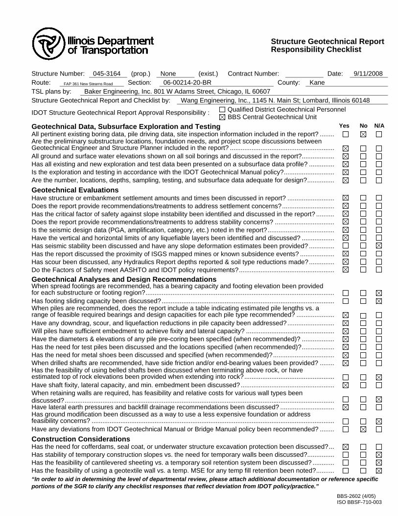
Structure Geotechnical ReportResponsibility Checklist
Structure Number: 045-3164 (prop.) None (exist.) Contract Number: Date: 9/11/2008 Route: FAP 361 New Stearns Road Section: 06-00214-20-BR County: Kane TSL plans by: Baker Engineering, Inc. 801 W Adams Street, Chicago, IL 60607 Structure Geotechnical Report and Checklist by: Wang Engineering, Inc., 1145 N. Main St; Lombard, Illinois 60148
IDOT Structure Geotechnical Report Approval Responsibility : Qualified District Geotechnical Personnel BBS Central Geotechnical Unit
Geotechnical Data, Subsurface Exploration and Testing Yes No N/A All pertinent existing boring data, pile driving data, site inspection information included in the report? ........ Are the preliminary substructure locations, foundation needs, and project scope discussions between Geotechnical Engineer and Structure Planner included in the report? ..........................................................
All ground and surface water elevations shown on all soil borings and discussed in the report?.................. Has all existing and new exploration and test data been presented on a subsurface data profile? .............. Is the exploration and testing in accordance with the IDOT Geotechnical Manual policy?............................ Are the number, locations, depths, sampling, testing, and subsurface data adequate for design?...............
Geotechnical Evaluations Have structure or embankment settlement amounts and times been discussed in report? .......................... Does the report provide recommendations/treatments to address settlement concerns?............................. Has the critical factor of safety against slope instability been identified and discussed in the report? .......... Does the report provide recommendations/treatments to address stability concerns? ................................. Is the seismic design data (PGA, amplification, category, etc.) noted in the report?..................................... Have the vertical and horizontal limits of any liquefiable layers been identified and discussed? .................. Has seismic stability been discussed and have any slope deformation estimates been provided? .............. Has the report discussed the proximity of ISGS mapped mines or known subsidence events? ................... Has scour been discussed, any Hydraulics Report depths reported & soil type reductions made?.............. Do the Factors of Safety meet AASHTO and IDOT policy requirements?.....................................................
Geotechnical Analyses and Design Recommendations When spread footings are recommended, has a bearing capacity and footing elevation been provided for each substructure or footing region?.........................................................................................................
Has footing sliding capacity been discussed?................................................................................................ When piles are recommended, does the report include a table indicating estimated pile lengths vs. a range of feasible required bearings and design capacities for each pile type recommended? .....................
Have any downdrag, scour, and liquefaction reductions in pile capacity been addressed?.......................... Will piles have sufficient embedment to achieve fixity and lateral capacity? ................................................. Have the diameters & elevations of any pile pre-coring been specified (when recommended)? .................. Has the need for test piles been discussed and the locations specified (when recommended)?.................. Has the need for metal shoes been discussed and specified (when recommended)?.................................. When drilled shafts are recommended, have side friction and/or end-bearing values been provided? ........ Has the feasibility of using belled shafts been discussed when terminating above rock, or have estimated top of rock elevations been provided when extending into rock?..................................................
Have shaft fixity, lateral capacity, and min. embedment been discussed?.................................................... When retaining walls are required, has feasibility and relative costs for various wall types been discussed?......................................................................................................................................................
Have lateral earth pressures and backfill drainage recommendations been discussed? .............................. Has ground modification been discussed as a way to use a less expensive foundation or address feasibility concerns? .......................................................................................................................................
Have any deviations from IDOT Geotechnical Manual or Bridge Manual policy been recommended? ........
Construction Considerations Has the need for cofferdams, seal coat, or underwater structure excavation protection been discussed?... Has stability of temporary construction slopes vs. the need for temporary walls been discussed?............... Has the feasibility of cantilevered sheeting vs. a temporary soil retention system been discussed? ............ Has the feasibility of using a geotextile wall vs. a temp. MSE for any temp fill retention been noted?.......... “In order to aid in determining the level of departmental review, please attach additional documentation or reference specific portions of the SGR to clarify any checklist responses that reflect deviation from IDOT policy/practice.”
BBS-2602 (4/05) ISO BBSF-710-003
TABLE OF CONTENTS
1.0 INTRODUCTION ...................................................................................................................... 1
2.0 PROJECT DESCRIPTION....................................................................................................... 1
3.0 EXISTING AND PROPOSED STRCUTURES ...................................................................... 2
4.0 PURPOSE AND SCOPE............................................................................................................ 2
5.0 GEOLOGIC SETTING ............................................................................................................. 2
6.0 METHODS OF INVESTIGATION.......................................................................................... 4
7.0 SUBSURFACE CONDITIONS................................................................................................. 5
8.0 ANALYSIS AND RECOMMENDATIONS ............................................................................ 6
9.0 CONSTRUCTION CONSIDERATIONS ............................................................................... 10
REFERENCES................................................................................................................................... 13 TABLES
1. Pile Design Data 2. Drilled Shaft Geotechnical Design Parameters 3. Soil Parameters for Lateral Load Analysis 4. Waterway Information 5. Foundation Design Scour Data
EXHIBITS 1. Project Location Map 2. Site Location Map 3. Site and Regional Geology Map 4. Boring Locations Plan 5. Subsurface Data Profile
APPENDIX A Boring Logs
APPENDIX B Laboratory Test Results
Geotechnical • Construction • Environmental Quality Engineering Services Since 1982
1145 North Main Street Lombard, Illinois 60148
Phone (630) 953-9928 www.wangeng.com
Geotechnical • Construction • Environmental Quality Engineering Services Since 1982
STRUCTURE GEOTECHNICAL REPORT
MULTI-USE PATH BRIDGE AND RAMP NEW STEARNS ROAD CONTRACT 4
IDOT STRUCTURE NUMBER 045-3164
KANE COUNTY PROJECT NO. P-91-051-07
FOR
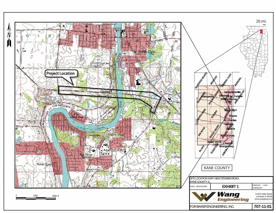
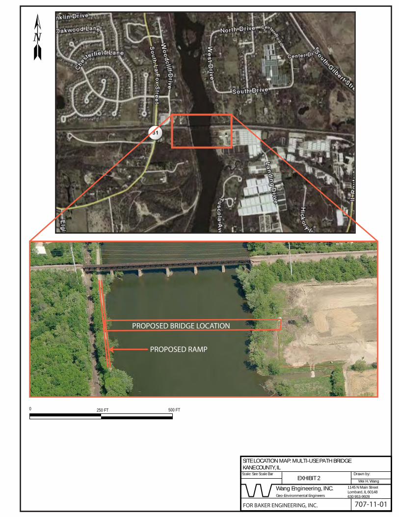
BAKER ENGINEERING, INC. 1.0 INTRODUCTION This report presents the results of subsurface investigation, laboratory testing, and geotechnical evaluation for the proposed Multi-Use Path (MUP) Bridge and Ramp structures. MUP Bridge will be along the Fox River Bridge and the ramp will be located along the Fox River on the west side of the Fox River Bridge. The project site is located in Kane County, Illinois. The Project and Site Location Maps are presented as Exhibits 1 and 2. 2.0 PROJECT DESCRIPTION The Stearns Road Corridor will include a new Fox River Bridge and a 4.6 mile new road alignment that extends from approximately the Kane/DuPage County line to Randall Road. The corridor is broken down into 6 stages. The proposed typical cross section of new Stearns Road consists of two 12-foot wide lanes in each direction separated by an 8- to 32-foot wide median with curb and gutter. Signalized intersection improvements will be provided at Randall Road/McDonald Road (the western terminus), McLean Boulevard, Illinois Route 25, Gilbert Street, and Dunham Road. The proposed roadway continues east of the intersection to join the four lane section of Stearns Road completed by DuPage County. Wang Engineering Inc. (WEI) was selected to provide geotechnical engineering services for the stage 4. The stage 4 scope of work includes construction of the new Stearns Road corridor from east of McLean Boulevard to Illinois Route 25 including a new structure over the Fox River. A new Multi-Use Path (MUP) Bridge will also be constructed adjacent to the Fox River Bridge. This stage also includes a new Stearns Road/IL Route 25 intersection that includes widening of IL Route 25, culvert under new Stearns Road and detention basins. In addition to this Structure Geotechnical Report, a Roadway Geotechnical Report has been prepared by WEI for the following items:
Fox River Bridge Multi-Use Path Bridge & Ramp WEI No. 707-11-01 September 11, 2008
Page 2
Geotechnical • Construction • Environmental Quality Engineering Services Since 1982
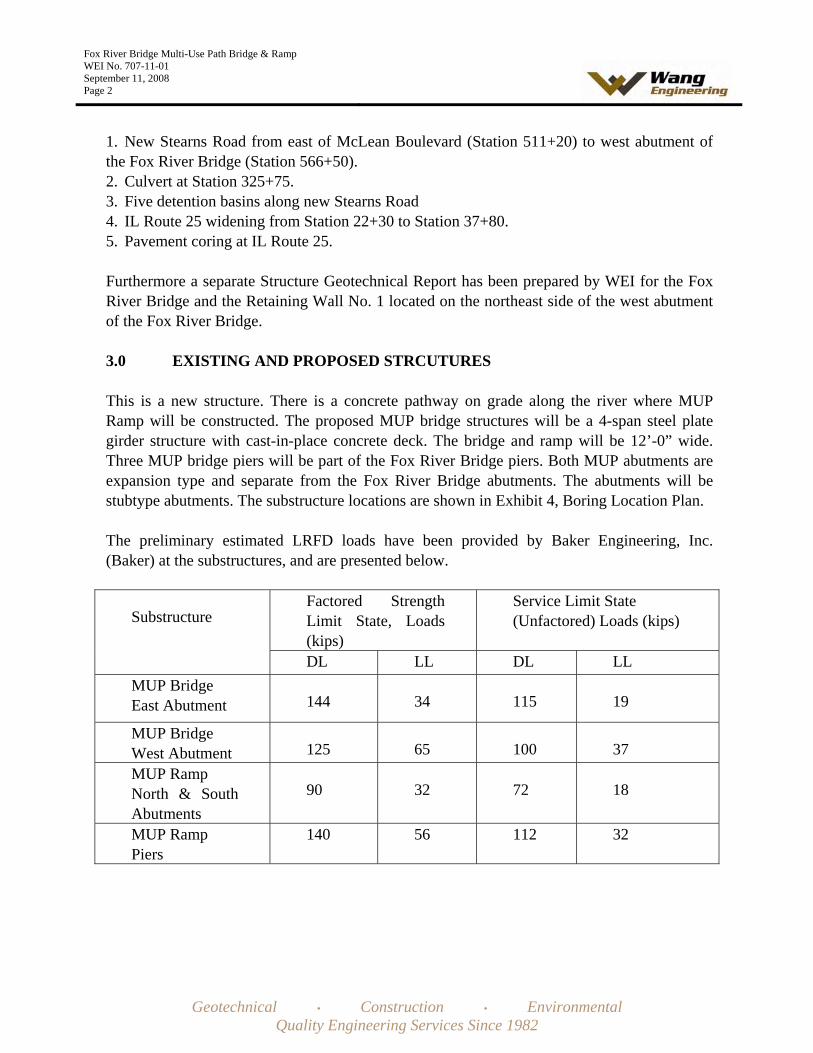
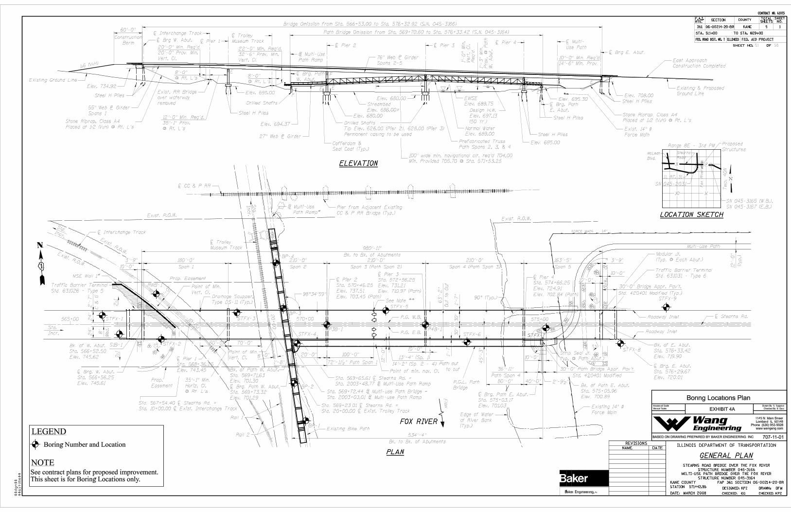
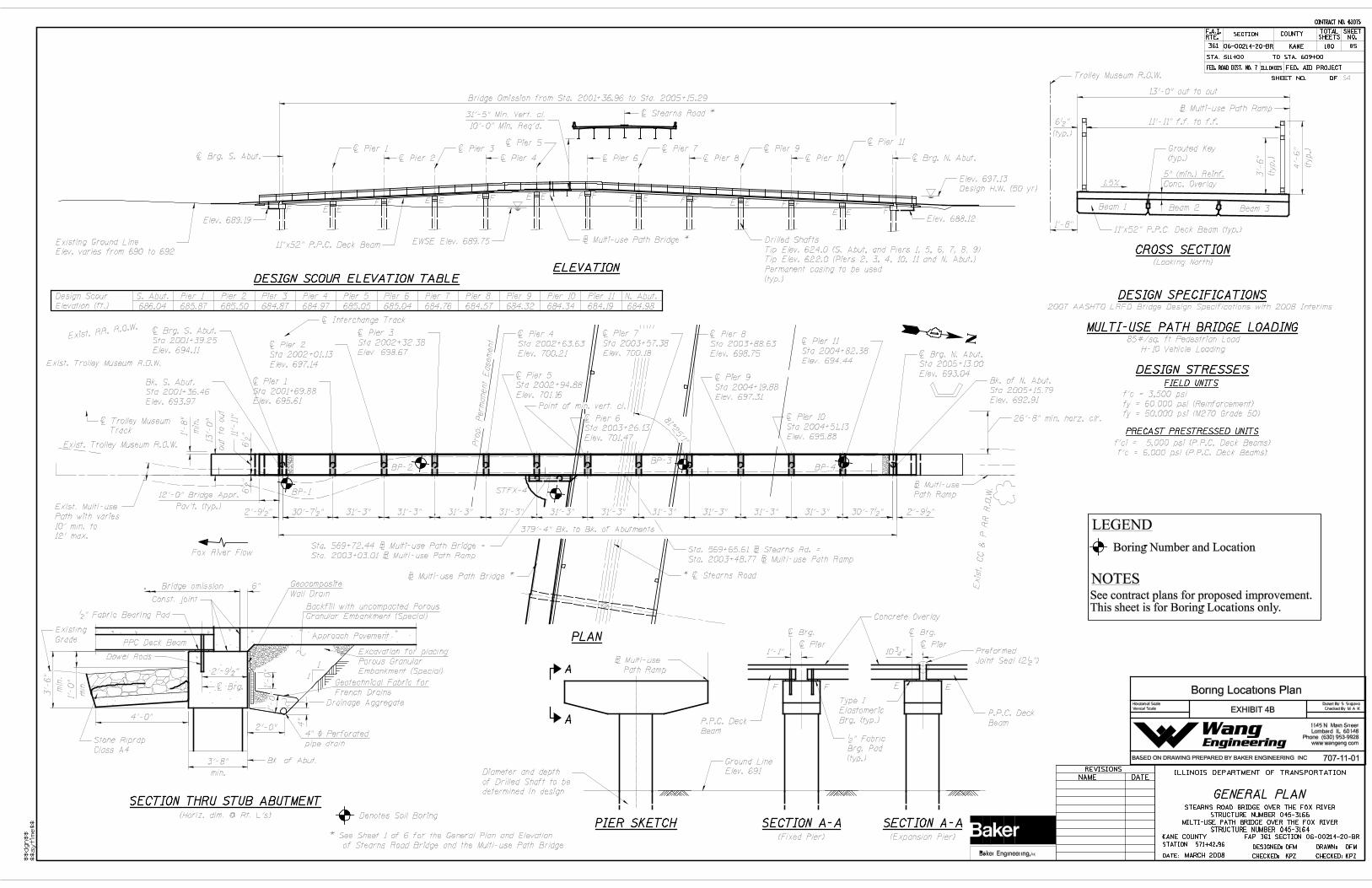
1. New Stearns Road from east of McLean Boulevard (Station 511+20) to west abutment of the Fox River Bridge (Station 566+50). 2. Culvert at Station 325+75. 3. Five detention basins along new Stearns Road 4. IL Route 25 widening from Station 22+30 to Station 37+80. 5. Pavement coring at IL Route 25. Furthermore a separate Structure Geotechnical Report has been prepared by WEI for the Fox River Bridge and the Retaining Wall No. 1 located on the northeast side of the west abutment of the Fox River Bridge. 3.0 EXISTING AND PROPOSED STRCUTURES This is a new structure. There is a concrete pathway on grade along the river where MUP Ramp will be constructed. The proposed MUP bridge structures will be a 4-span steel plate girder structure with cast-in-place concrete deck. The bridge and ramp will be 12’-0” wide. Three MUP bridge piers will be part of the Fox River Bridge piers. Both MUP abutments are expansion type and separate from the Fox River Bridge abutments. The abutments will be stubtype abutments. The substructure locations are shown in Exhibit 4, Boring Location Plan. The preliminary estimated LRFD loads have been provided by Baker Engineering, Inc. (Baker) at the substructures, and are presented below.
Factored Strength Limit State, Loads (kips)
Service Limit State (Unfactored) Loads (kips) Substructure
DL LL DL LL MUP Bridge East Abutment 144 34 115 19
MUP Bridge West Abutment 125 65 100 37 MUP Ramp North & South Abutments
90 32 72 18
MUP Ramp Piers
140 56 112 32
Fox River Bridge Multi-Use Path Bridge & Ramp WEI No. 707-11-01 September 11, 2008
Page 2
Geotechnical • Construction • Environmental Quality Engineering Services Since 1982
4.0 PURPOSE AND SCOPE The purpose of our geotechnical work was to investigate and evaluate the subsurface soil and groundwater conditions within this project area that would form a basis for foundation and earthwork design recommendations. Specifically, the scope of the work was as follows:
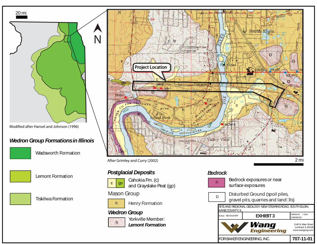
• To investigate by means of exploratory borings, the subsurface soils and ground water level conditions at the site to depths that will be influenced by the proposed construction; • To evaluate the physical properties of the soils underlying the site that will influence foundation design and construction; • To perform analyses and provide recommendations and data for the design and installation of foundations, including the suitable foundation type or types, bearing capacity, the elevation or elevations at which the foundations should be established, and the estimated foundation settlement; • To provide recommendations relative to construction operations and special design precaution that may be required; and • To provide a report summarizing the results of our studies, conclusions, and recommendations. 5.0 GEOLOGIC SETTING The project is located in the eastern part of Kane County. On the USGS “Geneva” quadrangle map, the project spans mainly sections 2 and 3 of Tier 40 North Range 8 East. The following review of published geologic data, with emphasis on factors that might influence the design and construction of the proposed engineering works, intends to place the project area within a geological framework and to confirm the dependability and consistency of our investigation results. Exhibit 3 illustrates the Site and Regional Geology. 5.1 Bedrock Geology The uppermost bedrock unit in Kane County consists of Silurian-age dolostones that rest on top of Ordovician-age shale and dolostone of the Maquoketa Group. The bedrock strata dip gently toward southeast (Curry et al., 1999; Dey et al., 2007). The bedrock crops out along the Fox River just south of the McLean Boulevard and IL Route 31 intersection. At the project site, the proglacial St. Charles Bedrock Valley shapes the bedrock topography: The valley is oriented NNE to SSW and has a relief of about 100 feet. The McLean Boulevard and IL Route 31 intersection is located above the western bank of the bedrock valley, whereas the proposed Fox River Bridge lies above the valley’s axis where the top of bedrock elevation measures 575 to 550 feet. The valley fill includes up to 100 feet of glacial outwash and till (Dey et al., 2007; Grimley and Curry, 2002).
Fox River Bridge Multi-Use Path Bridge & Ramp WEI No. 707-11-01 September 11, 2008
Page 3
Geotechnical • Construction • Environmental Quality Engineering Services Since 1982
5.2 Surficial Geology Glacial and postglacial deposits overlie the bedrock surface. Near the project area, the glacial deposits include diamictons of the Yorkville Member of the Lemont Formation and sand and gravel of the Henry Formation (Hansel and Johnson, 1996). Postglacial deposits are made up of sand and silt alluvium deposited by the Fox River (Cahokia Formation) and peat and muck accumulated in marshy depressions (Grayslake Peat). The Yorkville Member consists of low moisture content, high blow counts, low compressibility silty to silty clay loam diamicton (Bauer et al., 1991). It occurs at the east end of the project area and its thickness may range between 0 and 50 feet. The Yorkville Member rests over the Yorkville member deposit and it is overlain by medium dense to dense sand and gravel of the Henry Formation, which makes up most of the subgrade in the project area. The Henry Formation deposit may be as thick as 75 feet. Older diamictons may underline both the Yorkville Member and the Henry Formation (Grimley and Curry, 2002). Less than 20-foot thick Cahokia Alluvium (sand, silt, and clay) occurs in the project area, mostly east of the Fox River. A prominent deposit of peat, muck, organic silt and clay associated with the Grayslake Peat occur within a fen area just west of McLean Boulevard (Grimley and Curry, 2002). Our and previous subsurface investigations result fit into the local geologic context. The investigation revealed the lithological profile includes mostly outwash sand and gravel and clayey to silty diamictons. None of the borings drilled near the proposed MUP Bridge and ramp locations reached the top of the bedrock. 5.3 Mining Activity Areas of disturbed ground with spoil piles or removed earth in gravel pits, dolostone quarries, and landfills are present within or near the project area. Fox River Quarry (crushed stone) is located at the west end of the project. Another area with disturbed ground, probably associated with the Elgin-Wayne Landfill, is located at the east end of the project area. We assume there were no past coal mining activities at the proposed structure locations since the Kane County is not identified as coal producing area by Illinois State Geological Survey (ISGS, 2000). 5.4 Seismic Activity The 2002 US Geological Survey National Seismic Hazard Map (USGS, 2002) indicates for the Kane County area a peak ground acceleration of 2% of gravity, with a 10% probability of exceedance in 50 years. No active, major faults are present near the project area (Kolata, 2005).
Fox River Bridge Multi-Use Path Bridge & Ramp WEI No. 707-11-01 September 11, 2008
Page 4
Geotechnical • Construction • Environmental Quality Engineering Services Since 1982
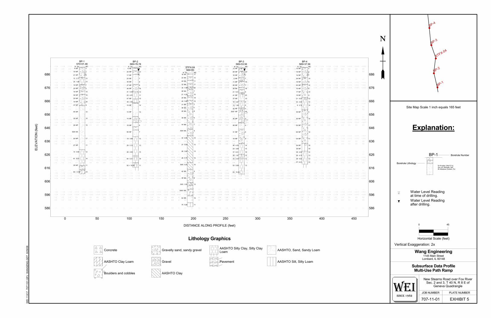
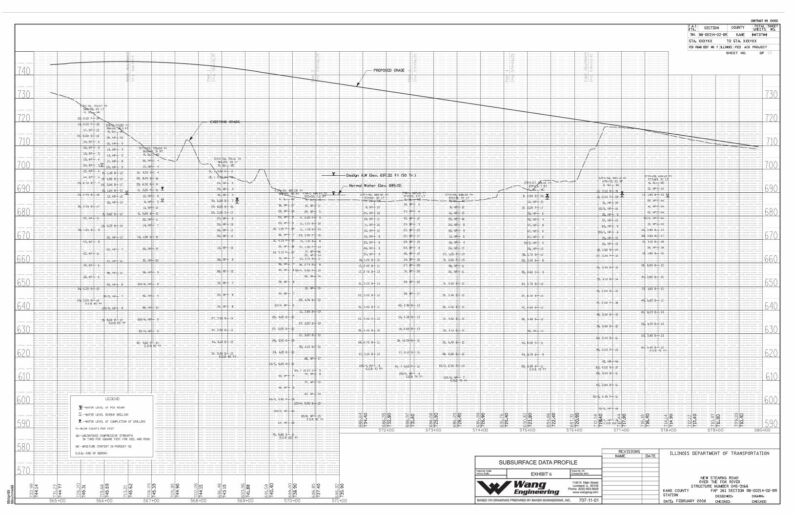
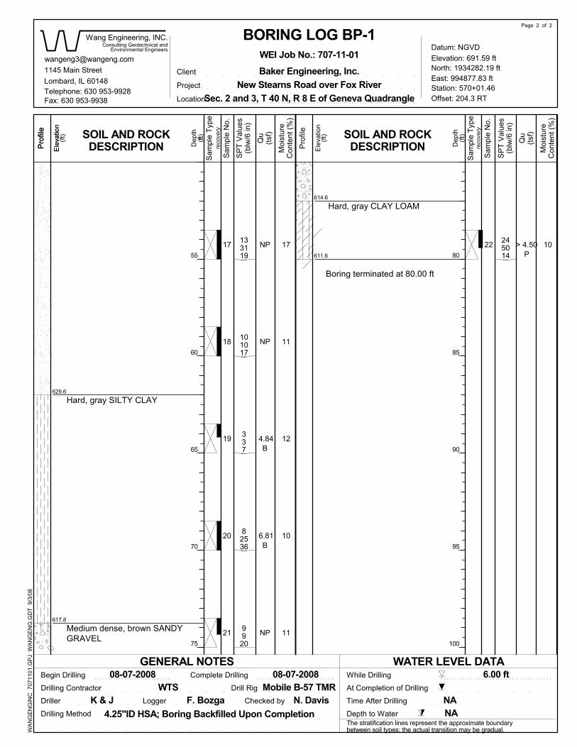
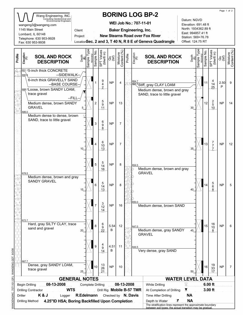
6.0 METHODS OF INVESTIGATION 6.1 Subsurface Investigation During the Phase I investigations, Testing Services Corporation (TSC) performed two structure borings, STFX-4 and STFX-7 to depths of 100 and 75feet below ground surface (bgs) respectively. Borings locations are shown in Exhibit 4. Boring logs are included in Appendix A. The subsurface exploration performed by WEI consisted of four structure borings (BP-1 through and BP-4) at the proposed MUP ramp. Borings were drilled during the period of August 7 and August 13, 2008. Borings were located in the field by WEI. After completion of borings, as-drilled borings coordinates locations were surveyed by WEI. Based on WEI coordinates, Baker provided station offset and grade elevation for each boring location. A Boring Locations Plan is included as Exhibits 4A and 4B. The survey information (ground surface elevation, coordinates, stations and offset) included in the attached boring logs (Appendix A). A truck mounted drilling rig, equipped with hollow stem augers, was used to advance and maintain an open borehole. Soil sampling was performed according to AASHTO T 206-87, "Penetration Test and Split Barrel Sampling of Soils." The soil was sampled at 2.5-foot intervals to a depth of 30 feet and at 5-foot intervals below 30 feet to termination depths. The clay soil in Borings BP-3 and BP-4 was sampled at 2.5-foot intervals between depths of 60 and 70 feet bgs. Borings were drilled few feet deeper than required by IDOT Geotechnical Manual guidelines in order to obtain necessary information for an adequate engineering analysis. Borings were drilled to depths ranging from 73.5 to 80 feet bgs. A WEI field engineer or geologist monitored the drilling activities and maintained field boring logs. The field logs included results of Standard Penetration Test (SPT) recorded as blows per 6 inches of penetration. Theses values are shown on the boring logs as SPT values. The N value shown in Exhibit 5 is the sum of the last two SPT numbers (blows per final 12 inches). The unconfined compressive strengths of cohesive soil samples were obtained in the field using Rimac Spring Tester on the split spoon samples. The soils were described and classified according to IDH classification system. All soil samples collected in the field were placed in sealed glass jars and transported to WEI Geotechnical Laboratory in Lombard, Illinois for further laboratory testing and examination. The field logs were finalized by an experienced geologist after verifying the field visual classifications and laboratory test results.
Fox River Bridge Multi-Use Path Bridge & Ramp WEI No. 707-11-01 September 11, 2008
Page 5
Geotechnical • Construction • Environmental Quality Engineering Services Since 1982
The soil samples will be retained in our laboratory for 60 days following the final report submittal. The samples will be discarded unless a specific written request is received as to their disposition. Groundwater observations were made during and at the end of drilling operations. Due to safety considerations, the land borehole was backfilled with bentonite chips mixed with soil cuttings immediately upon completion and patched with cement concrete at the surface. 6.2 Laboratory Testing Laboratory testing program included moisture content (AASHTO T 265) on all the soil samples. Atterberg Limits tests (AASHTO T 89 & T 90) and particle-size analyses (AASHTO T 88) were performed on selected soil samples. The field visual descriptions of the samples were reviewed in the laboratory. The laboratory test results are presented on the boring logs (Appendix A) and included in Appendix B. 7.0 SUBSURFACE CONDITIONS 7.1 Subsurface Soil Conditions Detailed descriptions of the subsurface conditions encountered in the borings are presented on the attached boring logs (Appendix A) and Subsurface Data Profile (Exhibit 5). Please note that the strata contact lines shown on logs and profiles represent approximate boundaries between soil types. The actual transition between soil types in the field may be different in horizontal and vertical directions. The subsurface investigation uncovered a vertical sequence of soil units laterally traceable throughout Borings STFX-4, STFX-7, and BP-1 through BP-4. From top to bottom, the sequence consists of five lithological units: (1) brown and gray sand to sandy gravel; (2) brown and gray clay to clay loam; and (3) brown and gray sand to sandy gravel, (4) gray very stiff to hard silty clay and (5) gray dense to very sense sand and gravel with intermittent thin layers of clay and silty loam. Only Boring STFX-4 penetrated into the fifth unit. Bedrock was not encountered in any of the borings. The bedrock is estimated to be at a depth of 120 feet below the river bed. This would place the bedrock immediately below the silty loam that was encountered in STFX-4. Details on the type of bedrock expected to be encountered in this area is presented in Section 5.1 Bedrock Geology of this report. 7.2 Groundwater Levels Water levels in the river Boring STFX-4 could not be recorded since it was drilled in the river. While drilling, BP-1 through BP-4, groundwater was encountered at a depth of 6 feet bgs.
Fox River Bridge Multi-Use Path Bridge & Ramp WEI No. 707-11-01 September 11, 2008
Page 6
Geotechnical • Construction • Environmental Quality Engineering Services Since 1982
Boring STFX-7 encountered groundwater at a depth of 3.5 feet bgs. At the completion of drilling, groundwater level was found at a depth of 3 feet bgs. We expect that the groundwater levels will fluctuate seasonally and with Fox River surface water level. 7.3 Seismic Considerations 7.3.1 Seismic Data The following seismic data is recommended for the design which should be shown on the bridge plans. Soil Profile Type: I (According to 2007 AASHTO LRFD Bridge Design and Specifications) Bedrock Acceleration Coefficient (A): 0.038g (According to the AASHTO Seismic Acceleration Coefficient Map and 2008 IDOT Bridge Design Manual) The Site Coefficient (S): 1.0 (Based on Soil Profile Type I) Seismic Performance Zone (SPZ): 1 (Based on the Bedrock Acceleration coefficient according to 2007 AASHTO LRFD Bridge Design and Specifications) 7.3.2 Liquefaction Potential Liquefaction analysis at each bridge structure boring was performed using a Simplified Procedure originally developed by Seed and Idriss (1982) and revised in 1990. The minimum factors of safety range between 1.8 and 3.1 considering groundwater level at the existing grade. A design earthquake with a magnitude of 7.5 was used in the analyses. The minimum factor of safety required by IDOT is 1.0. The liquefaction of the soils at the site is unlikely to occur and therefore, there is no need for any remedial treatment of the soils or foundation. 8.0 ANALYSIS AND RECOMMENDATIONS During the structure and foundation system studies conducted by Baker, WEI evaluated possible foundation solution that can be considered for support of the proposed bridge and ramp structures. All three MUP Bridge piers will be integral part of the Fox River Bridge piers. The recommendations for the Fox River Bridge piers are included in a separate SGR. The foundation options considered in the preliminary foundation evaluation for the MUP Bridge abutments and Ramp substructures were spread footing, driven piles and drilled shafts.
Fox River Bridge Multi-Use Path Bridge & Ramp WEI No. 707-11-01 September 11, 2008
Page 7
Geotechnical • Construction • Environmental Quality Engineering Services Since 1982
Based on the soil conditions encountered during our investigation, Baker and WEI concluded that the ramp substructures could be supported on drilled shafts and the bridge abutments on driven piles. The spread footings and pile footings for the ramp will require temporary soil retention system with groundwater control or cofferdams. The single drilled shaft eliminates the need for a cofferdam, seal coat and structure excavation. The east abutment of the MUP Bridge is proposed to be supported on the driven piles and MUP Ramp substructures on a single drilled shaft. Foundation design data and recommendations pertaining to construction are presented in subsequent sections of this report. 8.1 Foundation Recommendations 8.1.1 Bridge Abutments The metal shell cast-in-place (MSCIP) pile driving through very dense/hard soils will be difficult and could damage the pile toe and cause deformation at the pile head. Therefore, we do not recommend MSCIP concrete piles for the west and east abutments. The top of the dolomitic limestone bedrock is estimated at approximate Elevation 570. The pile length from the bottom of the pile cap to top of the limestone bedrock would be on the order of 120 feet. Based on the soil information from the borings, it appears that driving H-piles to top of bedrock, through very dense/very hard soils, will be very difficult and the refusal will be obtained before reaching top of the bedrock. Therefore, we do not recommend utilizing end bearing H-piles. The required driven capacity for steel H-piles installed as friction piles could be achieved with shorter lengths. Several H-piles options for the foundations could be considered. Driven H-pile foundations could be designed for various capacities. The pile capacity will be developed in skin friction between the pile surface and the soils above the tip with some end bearing capacity at the tip. The estimated pile lengths at each bridge abutment location for various H-pile sizes and capacities are shown in Tables 1A through 1C. The most economical pile sizes should be selected. The sections of the pile through the precored holes in the newly placed embankment were not considered in providing vertical pile load carrying capacity. Precoring is recommended to avoid downdrag load on the piles and is discussed in the subsequent section of the report. The maximum structural design capacity of the steel pile and the spacing should be as per IDOT Bridge Manual (IDOT 2006). Hard pile driving during installation might be experienced in very dense sand and gravel deposits containing potentially cobbles. Therefore, we recommend that the piles be installed with metal shoes. One test pile should be identified on the plans at each abutment which should be installed prior to production pile installation. There is no need for a full scale load test.
Fox River Bridge Multi-Use Path Bridge & Ramp WEI No. 707-11-01 September 11, 2008
Page 8
Geotechnical • Construction • Environmental Quality Engineering Services Since 1982
The soil immediately below the pile footing should not be considered as carrying any vertical load. The estimated lengths shown in the Tables 1A through 1C do not include any embedment into the pile footing. The estimated length to be shown on the bridge plans should include embedment in to the pile footing as per IDOT Bridge Manual (IDOT 2006). The base of all pile footings should be established at a minimum depth of 4 feet below the finished grade for frost protection. 8.1.2 Ramp Substructures It is our opinion that a deep foundation scheme consisting of drilled shaft established in hard clay stratum can be utilized for the support of the ramp substructures including MUP Bridge west abutment. The geotechnical recommendations for the design of drilled shafts are presented in Table 2. All shafts should be sized in 6 inches increments with a minimum diameter of 30 inches. A permanent liner in the granular soils should be provided. The Factored Resistance RR of drilled shafts in kips can be calculated as per equation 10.8.3.5-1, page 1-131 of AASHTO LRFD Bridge Design Specifications, 4th Edition 2007 (2007 AASHTO). The portions of the drilled shaft which should not be taken in contributing to the development of resistance through skin friction should be as specified in 2007 AASHTO. The reduction in resistance from group effects should also be evaluated as per 2007 AASHTO. The scour depth should also be considered in the drilled shaft design. 8.2 Downdrag Loads Negligible downdrag load due to the negative skin friction will occur on piles at the east abutment when soil strata move downward relative to the piles due to compression of the foundation soils. The west abutment will not retain any embankment. We recommend that the piles be installed in precored holes in the new embankment for the east abutment. 8.3 Lateral Design Pressures For the design of east abutment and wingwalls, we recommend linearly increasing lateral pressure of 40 and 72 pounds per square foot (psf) per foot of depth below finished grade for embankment slope of horizontal and 1V:2H respectively considering drainable backfill. When no approach slab is provided, additional lateral load from traffic should include a surcharge of 2 feet of soil considering unit weight of 120 pounds per cubic foot. The backfill and the drainage behind the abutments should be in accordance with IDOT Bridge Manual (IDOT 2006).
Fox River Bridge Multi-Use Path Bridge & Ramp WEI No. 707-11-01 September 11, 2008
Page 9
Geotechnical • Construction • Environmental Quality Engineering Services Since 1982
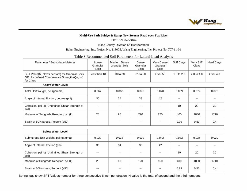
8.4 Resistance to Lateral Loads Batter piles can be considered to resist the lateral loads. For such pile footing, the horizontal component of the axial load on battered piles can be taken at full value. The use of battered shaft is not recommended due to their difficulty of construction and high cost. The required lateral capacity can be obtained by increasing the number of shafts or the shaft diameter. No allowance should be made for the frictional resistance of the cap concrete on soil. Lateral resistance from the soils from the proposed grade to the design scour depth, as per IDOT Bridge Design Manual (IDOT 2006), should be ignored. The lateral load capacity analysis of the piles/drilled shafts can be performed using computer program such as COMP 624P and L-pile. The estimated soil parameters that may be used for the analysis of stresses and deflection under lateral loads are presented in the attached Table 3. The geotechnical resistance factor of 1.0 should be used. The group action should be considered in calculating total lateral load resistance of the substructures. 8.5 Scour Potential The existing scour data is not available since there is no existing structure for the Fox River crossing at this location. The scour analysis was performed by Christopher B. Burke Engineering (CBBE) for the Fox River Bridge. The flood elevations are shown in Tables 4. The scour data at the MUP Bridge east abutment was not available. The scour elevations for the foundation design are shown in Table 5. The piles and drilled shafts should be designed so that the pile and shaft penetration after the design scour event satisfies the required axial and lateral resistance. The soil lost due to scour should not be considered in contributing the overburden stress in the soil below the scour zone. 8.6 Foundation Settlement The driven H-pile foundations designed and constructed as recommended will undergo negligible settlement (less than 0.5 inch). We performed settlement analyses for a single drilled shaft. The settlement considering applied pressure of 18 kips per square foot is estimated to be on the order of 0.50 inch for a 4-foot diameter straight drilled shaft. There would be an additional settlement due to elastic compression of the concrete shaft. 8.7 Embankment Slope Stability The maximum height of the embankment will be 10 feet at the east abutment. The embankments constructed to the design grades of 1V:2H or flatter are expected to be stable. The end slopes of 1V:2H are expected to be stable with additional resistance provided by the piles.
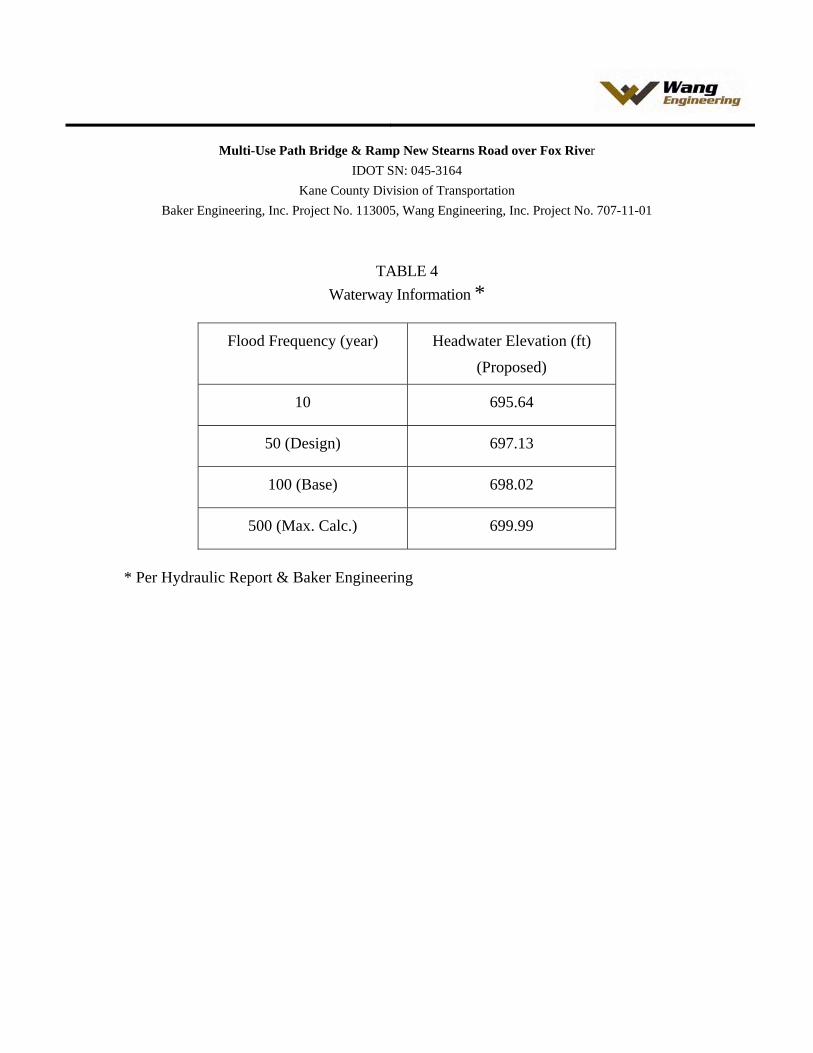
Fox River Bridge Multi-Use Path Bridge & Ramp WEI No. 707-11-01 September 11, 2008
Page 10
Geotechnical • Construction • Environmental Quality Engineering Services Since 1982
8.8 Embankment Settlement The pathway approach embankment immediately behind the east abutments will require approximately 10 feet of new fill above the existing grade. The approach embankments will have 1V:2H end slopes and 1V:2H or flatter side slopes. The placement of fill for the embankment will result in settlement of the underlying natural soils. Most of the settlement is expected to be occurring at the same rate as the construction of the embankment progresses. We anticipate that by the time the proposed embankment is built to the bottom of abutment footing, the soil would undergo most of the settlement in the area of the proposed abutment. Settlement within new embankment fill would also occur. For granular soil embankment, the majority of the settlement is expected to be completed by the end of construction. For cohesive soil embankment, a significant portion of total settlement within the embankment can also be expected to occur by the end of construction; however complete consolidation may take some time. As discussed earlier in the report, the piles should be installed in precored holes though the new embankment fill to avoid the downdrag load. 9.0 CONSTRUCTION CONSIDERATIONS
9.1 Excavation Due to the existing soil conditions and close proximity to the river it might not be possible to slope the excavation sidewalls near the river. If that’s the case, bracing with groundwater level control might be required. Temporary excavations required for other areas should have a slope of 1V:2H or flatter, as required to provide a stable side slopes. Foundation excavations should be performed in accordance with local, state, and federal regulations. 9.2 Dewatering Seepage water that does accumulate in open excavations at the east abutment location can be removed using the sump pump method. 9.3 Filling and Backfilling Structural fill used to attain the final design subgrade elevations should be IDOT gradation CA-6 or equivalent. This fill material should be free of organic matter and debris. Fill should be placed in lifts not exceeding 8 inches loose thickness and compacted to minimum 95 percent maximum dry density, as determined in accordance with AASTHO T-99, Standard Proctor Method. Any backfill should be pre-approved by the site engineer. The fill should be free of organic materials and debris. We recommend using a porous granular material, such as IDOT gradation FA-1/FA-2 or the equivalent, to backfill the proposed east abutment. All backfill material should
Fox River Bridge Multi-Use Path Bridge & Ramp WEI No. 707-11-01 September 11, 2008
Page 11
Geotechnical • Construction • Environmental Quality Engineering Services Since 1982
be compacted in lifts no greater than 8 inches loose thickness. Each layer should be compacted to minimum 95 percent maximum dry density, as determined by AASTHO T-99, Standard Proctor Method. 9.4 Cofferdam Cofferdam and seal coat will not be necessary for construction of the MUP ramp substructures supported on a single drilled shaft. 9.5 Drilled Shafts We recommend that a permanent casing with teeth at the bottom be installed in order to provide a good seal at top of the clay layer. The excavation below the casing in the clay should be performed with a dry method. After drilled shaft is completed to the required elevation, the base should be cleaned and inspected, the reinforcing cage placed, and the concrete can be discharged at the base using a tremie pipe or concrete pump. The drilled shafts should be constructed in accordance with Section 516 Drilled Shafts of the IDOT 2007 Standard Specifications for Road and Bridge Construction (IDOT 2007). 9.6 Construction Monitoring There is no need for a special construction monitoring for the foundations except normally required by the IDOT Standard Specifications, Special Provisions and Contract Plans. 9.7 Embankment Construction Bridge abutment fill should be constructed as early as possible in the project construction period in order to allow the embankments to adjust or settle under its own weight as much as possible prior to piles installation for the east abutment. The embankment construction should be performed in accordance with Section 205 of the IDOT Standard Specifications for Road and Bridge Construction (IDOT 2007).
Fox River Bridge Multi-Use Path Bridge & Ramp WEI No. 707-11-01 September 11, 2008
Page 12
Geotechnical • Construction • Environmental Quality Engineering Services Since 1982
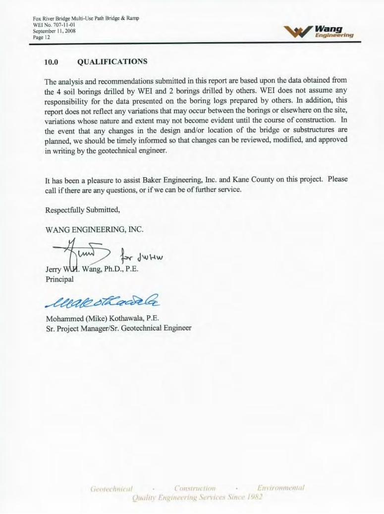
10.0 QUALIFICATIONS The analysis and recommendations submitted in this report are based upon the data obtained from the 4 soil borings drilled by WEI and 2 borings drilled by others. WEI does not assume any responsibility for the data presented on the boring logs prepared by others. In addition, this report does not reflect any variations that may occur between the borings or elsewhere on the site, variations whose nature and extent may not become evident until the course of construction. In the event that any changes in the design and/or location of the bridge or substructures are planned, we should be timely informed so that changes can be reviewed, modified, and approved in writing by the geotechnical engineer. It has been a pleasure to assist Baker Engineering, Inc. and Kane County on this project. Please call if there are any questions, or if we can be of further service. Respectfully Submitted, WANG ENGINEERING, INC. Jerry W.H. Wang, Ph.D., P.E. Principal Mohammed (Mike) Kothawala, P.E. Sr. Project Manager/Sr. Geotechnical Engineer
Fox River Bridge Multi-Use Path Bridge & Ramp WEI No. 707-11-01 September 11, 2008
Page 13
Geotechnical • Construction • Environmental Quality Engineering Services Since 1982
REFERENCES AASHTO 2007. LRFD Bridge Design Specifications. American Association of State Highway and Transportation Officials, Inc., Washington, D.C.
Bauer, R.A., Curry, B.B., Graese, A.M., Vaiden, R.C., Su, W.J. and Hasek, M.J., 1991, Geotechnical Properties of Selected Pleistocene, Silurian, and Ordovician Deposits of Northeastern Illinois. Illinois State Geological Survey, 69 pp.
CC&P/Stearns Road Corridor Design Report, May 2006, Kane County and Illinois Department of Transportation
Christopher B. Burke Engineering, Ltd., March 2004, Hydraulic Report, Stearns Road Bridge over Fox River
Coduto, Donald P., 2001, Foundation Design, Prentice-Hall, Inc.
Curry, B.B., Grimley, D.A. and Stravers, J.A., 1999, Quaternary Geology, Geomorphology, and Climatic History of Kane County, Illinois, 40 pp.
Dey, W.S., A.M., Davis and B.B. Curry, 2007, Bedrock Geology, Kane County, Illinois: In: ISGS, Illinois County Geologic Map, ICGM Kane-BG, 1:100,000. Illinois State Geological Survey,
FHWA, August 1999, Drilled Shafts: Construction Procedures and Design Methods, Publication No. FHWA-IF99-025
FHWA, 1997, Geotechnical Engineering Circular No.3, Design Guidance: Geotechnical Earthquake Engineering for Highways
Graese, A.M., R.A. Bauer, B.B. Curry, R.C. Vaiden, W.G. Dixon, Jr., and J.P. Kempton, 1988, Geological-geotechnical studies for siting the Superconducting Super Collider in Illinois: Regional Summary: Illinois State Geological Survey, Environmental Geology Notes 123, 100 p.
Grimley, D.A., B.B., Curry, 2002, Surficial Geology Map of the Geneva 7.5-minute Quadrangle, Kane County, Illinois. In: ISGS, Illinois Geological Quadrangle Map IGQ Geneva-SG, 1:24,000. Illinois State Geological Survey
Hansel, A.K. and Johnson, W.H., 1996, Wedron and Mason Groups: Lithostratigraphic Reclassification of the Wisconsin Episode, Lake Michigan Lobe Area: Illinois State Geological Survey, Champaign, 116 p.
IDOT 1999. Geotechnical Manual. Illinois Department of Transportation.
Fox River Bridge Multi-Use Path Bridge & Ramp WEI No. 707-11-01 September 11, 2008 Page 14
IDOT 2007. Standard Specifications for Road and Bridge Construction. Illinois Department of Transportation.
IDOT 2004. Drainage Manual. Illinois Department of Transportation.
ISGS May 2000. Directory of Coal Mines in Illinois, ISGS.
Kulhawy, F.H. December 1997. Drilled Shaft Foundations in Soil and Rock, University of Wisconsin, Milwaukee.
Kolata, D.R., 2005, Bedrock Geology of Illinois. In: ISGS Map 14, 1:500, 000. Illinois State Geological Survey.
USGS, 2002, National & Regional Seismic Hazard Maps, 2008. United States Geological Survey, http://earthquake.usgs.gov/research/hazmaps/.
William, H.B., 1971, Summary of the Geology of the Chicago Area: ISGS Circular C460. Illinois State Geological Survey, Urbana, 77 p.
Geotechnical • Construction • Environmental Quality Engineering Services Since 1982

TABLES
Geotechnical • Construction • Environmental Quality Engineering Services Since 1982

Multi-Use Path Bridge & Ramp New Stearns Road over Fox River IDOT SN: 045-3164
Kane County Division of Transportation Baker Engineering, Inc. Project No. 113005, Wang Engineering, Inc. Project No. 707-11-01
Table 1A Pile Design Data for HP 10x42
Estimated pile length below footing, ft Sub-Structure
ID
Reference Boring Number
Bottom of Footing
Elevation
Precoring
To
Elevation
Pile Capacity Calculated
From Elevation NRB: 210
kips NRB: 240
kips NRB: 270
kips NRB: 300
kips NRB: 330
kips
West Abutment
STFX-4 694.37 687.0 687.0 38 41 44 46 48
East Abutment
STFX-7 695.30 691.0 691.0 23 24 26 27 29
1. The estimated length does not include any embedment into the footing. For estimated length to be shown on the plans, add embedment in
accordance with IDOT Bridge Manual. 2. NRB = Nominal Required Bearing, FRA = Factored Resistance Available, FRA=0.5 times NRB 3. Maximum NRB for HP 10x42 is 335 kips
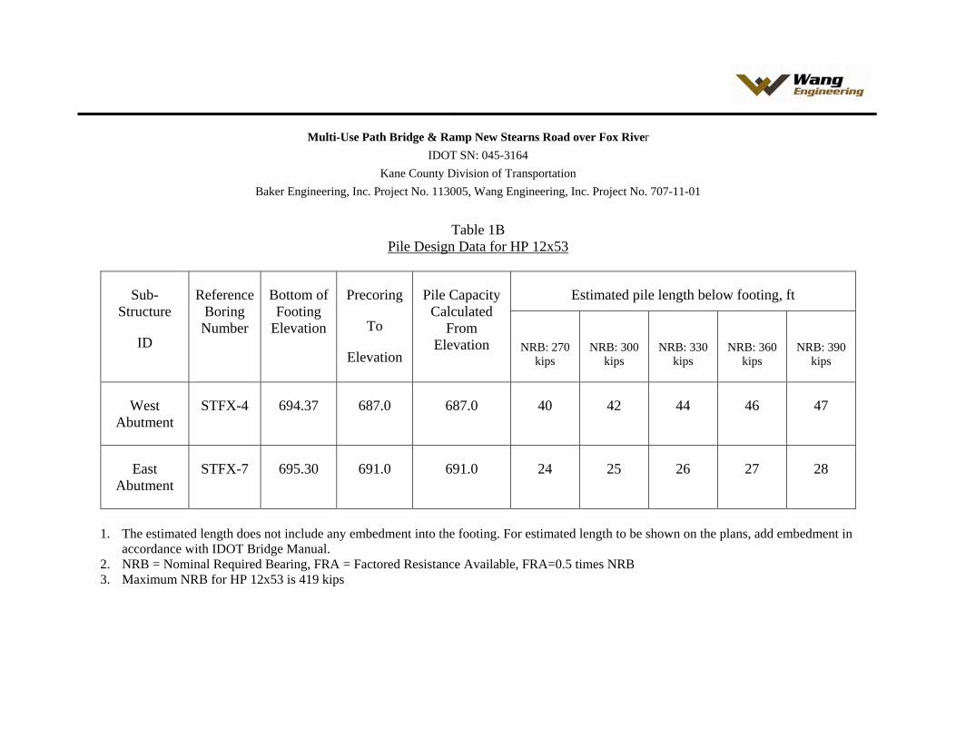
Multi-Use Path Bridge & Ramp New Stearns Road over Fox River IDOT SN: 045-3164
Kane County Division of Transportation Baker Engineering, Inc. Project No. 113005, Wang Engineering, Inc. Project No. 707-11-01
Table 1B Pile Design Data for HP 12x53
Estimated pile length below footing, ft Sub-Structure
ID
Reference Boring Number
Bottom of Footing
Elevation
Precoring
To
Elevation
Pile Capacity Calculated
From Elevation NRB: 270
kips NRB: 300
kips NRB: 330
kips NRB: 360
kips NRB: 390
kips
West Abutment
STFX-4 694.37 687.0 687.0 40 42 44 46 47
East Abutment
STFX-7 695.30 691.0 691.0 24 25 26 27 28
1. The estimated length does not include any embedment into the footing. For estimated length to be shown on the plans, add embedment in
accordance with IDOT Bridge Manual. 2. NRB = Nominal Required Bearing, FRA = Factored Resistance Available, FRA=0.5 times NRB 3. Maximum NRB for HP 12x53 is 419 kips

Multi-Use Path Bridge & Ramp New Stearns Road over Fox River IDOT SN: 045-3164
Kane County Division of Transportation Baker Engineering, Inc. Project No. 113005, Wang Engineering, Inc. Project No. 707-11-01
Table 1C Pile Design Data for HP 14x73
Estimated pile length below footing, ft Sub-Structure
ID
Reference Boring Number
Bottom of Footing
Elevation
Precoring
To
Elevation
Pile Capacity Calculated
From Elevation NRB: 300
kips NRB: 330
kips NRB: 360
kips NRB: 390
kips NRB: 420
kips
West Abutment
STFX-4 694.37 687.0 687.0 38 40 42 44 46
East Abutment
STFX-7 695.30 691.0 691.0 23 24 25 26 27
1. The estimated length does not include any embedment into the footing. For estimated length to be shown on the plans, add embedment in
accordance with IDOT Bridge Manual. 2. NRB = Nominal Required Bearing, FRA = Factored Resistance Available, FRA=0.5 times NRB 3. Maximum NRB for HP 14x73 is 578 kips
Multi-Use Path Bridge & Ramp New Stearns Road over Fox River IDOT SN: 045-3164
Kane County Division of Transportation Baker Engineering, Inc. Project No. 113005, Wang Engineering, Inc. Project No. 707-11-01
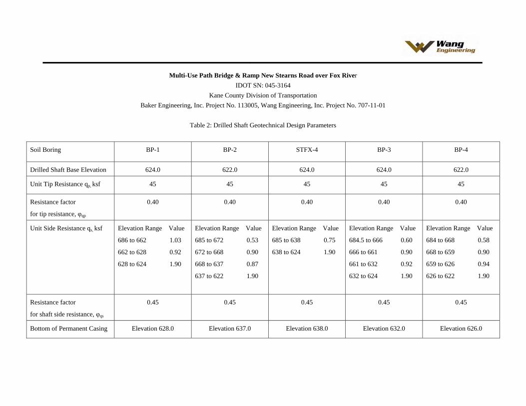
Table 2: Drilled Shaft Geotechnical Design Parameters
Soil Boring BP-1 BP-2 STFX-4 BP-3 BP-4
Drilled Shaft Base Elevation 624.0 622.0 624.0 624.0 622.0
Unit Tip Resistance qp, ksf 45 45 45 45 45
Resistance factor
for tip resistance, φqp
0.40 0.40 0.40 0.40 0.40
Unit Side Resistance qs, ksf
Elevation Range Value
686 to 662 1.03
662 to 628 0.92
628 to 624 1.90
Elevation Range Value
685 to 672 0.53
672 to 668 0.90
668 to 637 0.87
637 to 622 1.90
Elevation Range Value
685 to 638 0.75
638 to 624 1.90
Elevation Range Value
684.5 to 666 0.60
666 to 661 0.90
661 to 632 0.92
632 to 624 1.90
Elevation Range Value
684 to 668 0.58
668 to 659 0.90
659 to 626 0.94
626 to 622 1.90
Resistance factor
for shaft side resistance, φqs
0.45 0.45 0.45 0.45 0.45
Bottom of Permanent Casing Elevation 628.0 Elevation 637.0 Elevation 638.0 Elevation 632.0 Elevation 626.0
Multi-Use Path Bridge & Ramp New Stearns Road over Fox River IDOT SN: 045-3164
Kane County Division of Transportation Baker Engineering, Inc. Project No. 113005, Wang Engineering, Inc. Project No. 707-11-01
Table 3 Recommended Soil Parameters for Lateral Load Analysis
Parameter / Subsurface Material Loose Granular
Soils
Medium Dense Granular Soils
Dense Granular
Soils
Very Dense Granular
Soils
Stiff Clays Very Stiff Clays
Hard Clays
SPT Value(N, blows per foot) for Granular Soils OR Unconfined Compressive Strength (Qu, tsf) for Clays
Less than 10 10 to 30 31 to 50 Over 50 1.0 to 2.0 2.0 to 4.0 Over 4.0
Above Water Level
Total Unit Weight, pci (gamma) 0.067 0.068 0.075 0.078 0.069 0.072 0.075
Angle of Internal Friction, degree (phi) 30 34 38 42 -- -- --
Cohesion, psi (c) (Undrained Shear Strength of soil)
--- -- -- -- 10 20 30
Modulus of Subgrade Reaction, pci (k) 25 90 220 270 400 1030 1710
Strain at 50% stress, Percent (e50) --- -- -- -- 0.79 0.50 0.4
Below Water Level
Submerged Unit Weight, pci (gamma) 0.029 0.032 0.039 0.042 0.033 0.036 0.039
Angle of Internal Friction (phi) 30 34 38 42 -- -- --
Cohesion, psi (c) (Undrained Shear Strength of soil)
--- -- -- -- 10 20 30
Modulus of Subgrade Reaction, pci (k) 20 60 120 150 400 1030 1710
Strain at 50% stress, Percent (e50) --- -- -- -- 0.79 0.50 0.4
Boring logs show SPT Values number for three consecutive 6 inch penetration. N value is the total of second and the third numbers.
Multi-Use Path Bridge & Ramp New Stearns Road over Fox River IDOT SN: 045-3164
Kane County Division of Transportation Baker Engineering, Inc. Project No. 113005, Wang Engineering, Inc. Project No. 707-11-01
TABLE 4
Waterway Information *
Flood Frequency (year) Headwater Elevation (ft)
(Proposed)
10 695.64
50 (Design) 697.13
100 (Base) 698.02
500 (Max. Calc.) 699.99
* Per Hydraulic Report & Baker Engineering
Multi-Use Path Bridge & Ramp New Stearns Road over Fox River IDOT SN: 045-3164
Kane County Division of Transportation Baker Engineering, Inc. Project No. 113005, Wang Engineering, Inc. Project No. 707-11-01
TABLE 5
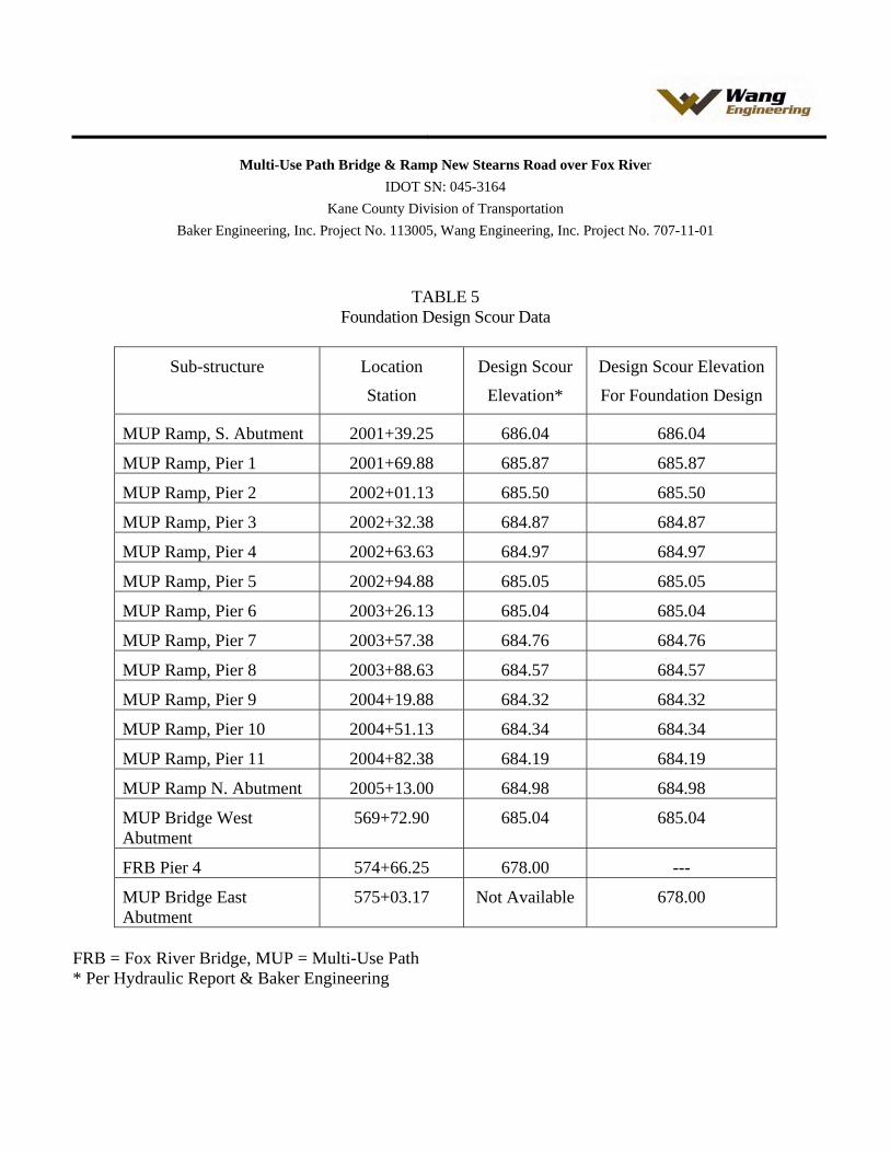
Foundation Design Scour Data
Sub-structure Location
Station
Design Scour
Elevation*
Design Scour Elevation
For Foundation Design
MUP Ramp, S. Abutment 2001+39.25 686.04 686.04
MUP Ramp, Pier 1 2001+69.88 685.87 685.87
MUP Ramp, Pier 2 2002+01.13 685.50 685.50
MUP Ramp, Pier 3 2002+32.38 684.87 684.87
MUP Ramp, Pier 4 2002+63.63 684.97 684.97
MUP Ramp, Pier 5 2002+94.88 685.05 685.05
MUP Ramp, Pier 6 2003+26.13 685.04 685.04
MUP Ramp, Pier 7 2003+57.38 684.76 684.76
MUP Ramp, Pier 8 2003+88.63 684.57 684.57
MUP Ramp, Pier 9 2004+19.88 684.32 684.32
MUP Ramp, Pier 10 2004+51.13 684.34 684.34
MUP Ramp, Pier 11 2004+82.38 684.19 684.19
MUP Ramp N. Abutment 2005+13.00 684.98 684.98
MUP Bridge West Abutment
569+72.90 685.04 685.04
FRB Pier 4 574+66.25 678.00 ---
MUP Bridge East Abutment
575+03.17 Not Available 678.00
FRB = Fox River Bridge, MUP = Multi-Use Path * Per Hydraulic Report & Baker Engineering

EXHIBITS
Geotechnical • Construction • Environmental Quality Engineering Services Since 1982
N
2000 ft
KANE C OUN T Y
20 mi .
0 4000
EXHIBIT 1
1145 N. Main StreetLombard, IL 60148
www.wangeng.com
DRAWN BY:
CHECKED BY:
FOR BAKER ENGINEERING, INC. 707-11-01
SITE LOCATION MAP: NEW STEARNS ROAD,KANE COUNTY, IL.
SCALE: SEE SCALE BARY. SHIU
Wang Engineering, INC.Geo-Environmental Engineers
1145 N Main StreetLombard, IL 60148630 953-9928
Scale: See Scale Bar Drawn by:EXHIBIT 2
Wei H. Wang
707-11-01FOR BAKER ENGINEERING, INC.
N
500 FT
SITE LOCATION MAP: MULTI-USE PATH BRIDGE KANE COUNTY, IL
0 250 FT
PROPOSED BRIDGE LOCATION
PROPOSED RAMP
Postglacial Deposits
Wedron Group Formations in Illinois
Wadsworth Formation
Lemont Formation
Tiskilwa Formation
Modified after Hansel and Johnson (1996)
After Grimley and Curry (2002)
Bedrock exposures or near surface exposures
20 mi
Cahokia Fm. (c)and Grayslake Peat (gp)
R
Bedrock
cc gp
Wedron GroupYorkville Member: Lemont Formation
2 mi
h
Mason Group
Henry Formation D
Disturbed Ground (spoil piles, gravel pits, quarries and landfills)
N
EXHIBIT 3
1145 N. Main StreetLombard, IL 60148
www.wangeng.com
DRAWN BY:
CHECKED BY:
FOR BAKER ENGINEERING, INC. 707-11-01
SITE AND REGIONAL GEOLOGY: NEW STEARNS ROAD, SOUTH ELGIN,KANE COUNTY, IL.
SCALE: SEE SCALE BARY. SHIU
GENERAL PLAN
N
LOCATION SKETCH
2
Fox R
iver
Tw
p. 40N
Range 8E - 3rd PM
3
10 11
Proposed
Structures
ELEVATION
S1
Elev. 680.00
Drilled Shafts
Tip Elev. 626.00 (Pier 2), 628.00 (Pier 3)
Permanent casing to be used
Streambed
Elev. 686.00|
Elev. 695.00
Stone Riprap, Class A4
Placed at 1:2 (V:H) @ Rt. L’s
Elev. 708.00
Exist. 14" }
Force Main
Elev. 685.00
Stone Riprap, Class A4
Placed at 1:2 (V:H) @ Rt. L’s
Elev. 734.92
76" Web ‘ Girder
Spans 2-5
~ Pier 1~ Pier 2 ~ Pier 3
~ Pier 4
~ Trolley
Museum Track
~ Interchange Track
~ Multi-
Use Path
10"-0" Min. Req’d.
14’-6" Min. Prov.
20’-0" Min. Req’d.
20’-0" Prov. Min.
Vert. Cl.
EE
FE
E E
Exist. RR Bridge
over waterway
removed
8’-0"
@ Rt. {’s
Design H.W.
Elev. 697.13
(50 Yr.)
~ Brg E. Abut.
~ Brg W. Abut.
22’-0" Min. Req’d.
32’-6" Prov. Min.
Vert. Cl.
8’-0"
@ Rt. {’s
12’-0" Min. Req’d.
35’-1" Prov.
@ Rt. {’s
55" Web ‘ Girder
Spans 1
E
F FF
E
EE
Elev. 694.37
Elev. 695.30
~ Brg. Path
E. Abut.
F
~ Brg. Path
W. Abut.
\ Multi-Use
Path Ramp
1
1’-
3" M
in.
Prov. @
Path
W
. A
but.
1’-
0" M
in.
Vert.
Cl.
R
eq’d
.
100’ wide min. navigational clr. req’d 704.00
Min. Provided 705.70 @ Sta. 571+53.25
SN 045-2031
IL RT. 31
McLean
Blvd.
Bridge Omission from Sta. 566+53.00 to Sta. 576+32.92 (S.N. 045-3166)
Path Bridge Omission from Sta. 569+70.60 to Sta. 576+33.42 (S.N. 045-3164)
Steel H Piles
Steel H Piles
Steel H Piles
Steel H Piles
Steel H Piles
Existing & Proposed
Ground Line
East Approach
Construction Completed
Elev. 680.00
1:6 (V:H)
60’-0"
Construction
Berm
Existing Ground Line
EWSE
Elev. 689.75
Normal Water
Elev. 689.00
Prefabricated Truss
Path Spans 2, 3, & 4Cofferdam &
Seal Coat (Typ.)
Drilled Shafts
KPZ
GG
DFM
KPZ
SN 045-3165 (W.B.),
SN 045-3167 (E.B.)
27" Web ‘ Girder
Stearns
Road
STATION 571+42.96
KANE COUNTY FAP 361 SECTION 06-00214-20-BR
$$
dg
n$
$
$$syti
me$$
OFSHEET NO. OF
REVISIONS
NAME DATEILLINOIS DEPARTMENT OF TRANSPORTATION
SECTION COUNTY
ILLINOIS FED. AID PROJECT
TOTAL
SHEETS
SHEET
NO.F.A.I.
RTE.
DATE:Baker Engineering, Inc.
CONTRACT NO. 63075
FED. ROAD DIST. NO. 7
CHECKED:
DRAWN:
CHECKED:
DESIGNED:
STA. 511+00 TO STA. 609+00
S5
06-00214-20-BR361 KANE
MARCH 2008
STEARNS ROAD BRIDGE OVER THE FOX RIVER
STRUCTURE NUMBER 045-3166
MILTI-USE PATH BRIDGE OVER THE FOX RIVER
STRUCTURE NUMBER 045-3164
5
PLAN
FOX RIVER
980’-11"
Bk. to Bk. of Abutments
3’-9"3’-9"
Traffic Barrier Terminal
Std. 631031 - Type 6
Bk. of E. Abut.
Sta. 576+33.42
Elev. 719.90
Roadway Inlet
Roadway Inlet
30’-0" Bridge Appr. Pav’t.
Std. 420401 Modified (Typ.)
2:1
2:1
10’-0"
10’-0"
40’-0"80’-0"
~ Brg. E. Abut.
Sta. 576+29.67
Elev. 720.01
90%%d (Typ.)
Edge of Water
at River Bank
(Typ.)
10’-0"
2:1
2:1
~ Pier 4
Sta. 574+66.25
Elev. 724.91
63
’-2
"
Out
to O
ut
30’
30’
1’-
7"
1’-
7"
P.G. W.B.
P.G. E.B.
10’-0"
100’-0"20’-0"
70’-0"
~ Pier 2
Sta. 570+46.25
Elev. 737.51
~ Pier 3
Sta. 572+56.25
Elev. 731.21
Bk. of W. Abut.
Sta. 566+52.50
Elev. 745.62
35’-1" Min.
Horiz. Cl.
@ Rt. L’s
Traffic Barrier Terminal
Std. 631026 - Type 5
60’-0"
Drainage Scupper,
Type DS-11 (Typ.)
Pier from Adjacent Existing
CC & P RR Bridge (Typ.)
~ CC & P RR
Sta.
Incr.
Sta.Incr.
~ Interchange Track
Sta
.
Incr.
~ Trolley
Museum Track
Point of Min.
Vert. Cl. 8’-0"
Existing Bike Path
Rail 2
Rail 1
Existing 14" }
Force Main
Flo
w
\ Multi-Use
Path Ramp*
~ Brg. W. Abut.
Sta. 566+56.25
Elev. 745.61
Multi-Use Path
2:1
Bk. of Path W. Abut.
Sta. 569+71.63
Elev. 701.30
~ Brg. Path W. Abut.
Sta. 569+73.32
Elev. 701.29
~ Pier 1
Sta. 568+36.25
Elev. 743.45
180’-0"
Span 1
210’-0"
Span 2
210’-0"
Span 3 (Path Span 2)
210’-0"
Span 4 (Path Span 3)
163’-5"
Span 5
Elev. 703.45 (Path)
Elev. 710.97 (Path)
36’-11"
Path Span 4
MSE Wall 1*
See Note **
Exist. R.O.W.Exist. R.O.W.
Exist. R.O.W.Exist. R.O.W.
45’-3"
Elev. 702.84 (Path)
~ Brg. Path E. Abut.
Sta. 575+03.17
Elev. 701.03
Bk. of Path E. Abut.
Sta. 575+05.96
Elev. 700.89
30’-0" Path Bridge Appr. Pav’t.
Std. 420401 Modified
10’-0"
Modular Jt.
(Typ. @ Each Abut.)
12’-
0"
(typ.)
2’-9 1/2 "P.G.L. Path
Bridge
2:1
14’-2" (Sp. 2 - 4)
Point of min. nav. Cl.
Path out
to out
Strip Seal Jt.
(typ. @ Path Abut.)
98^34’59"
12’-
0"
~ Stearns Rd.
Prop. Easement
Prop.
Easement
Sta. 569+65.61 ~ Stearns Rd. =
Sta. 2003+48.77 \ Multi-Use Path Ramp
Sta. 569+72.44 \ Multi-use Path Bridge =
Sta. 2003+03.01 \ Multi-use Path Ramp
Sta. 569+23.01 ~ Stearns Rd. =
Sta. 20+00.00 ~ Exist. Trolley Track
Sta. 567+54.40 ~ Stearns Rd. =
Sta. 10+00.00 ~ Exist. Interchange Track
72’-11 1/2 " Path Span 11’-8"
534’-4"
Bk. to Bk. of Abutments
13’-4" (Sp. 1)
Horizontal Scale:
Vertical Scale:
707-11-01
1145 N. Main Street
Lombard, IL 60148
Phone: (630) 953-9928
www.wangeng.com
Boring Locations PlanDrawn By: S. Sugiarto
Checked By: E. Datz EXHIBIT 4A
BASED ON DRAWING PREPARED BY BAKER ENGINEERING, INC.
LEGEND
Boring Number and Location
See contract plans for proposed improvement.
This sheet is for Boring Locations only.
NOTE
565+00 570+00 575+00STFX-1
STFX-2
STFX-3
STFX-4
STFX-5
STFX-7
STFX-8
STFX-9
Med
.
24’
24’
8’
2’-7
"
C &
G
8’-
0"
20+
00
10+00
Point of Min.
Vert. Cl.
STFX-6
FORCE MAIN 14"
P4B-1P3B-1
S1B-1
2000+
00
2005+
00
STFX-7
BP-1
BP-2
BP-3
BP-4
RWB-1
3
Denotes Soil Boring
Tw
p. 40N
Range 8E - 3rd PMF
ox R
iver
2
Bridge Omission from Sta. 2001+36.96 to Sta. 2005+15.29
31’-3" 31’-3" 31’-3" 31’-3" 31’-3" 31’-3" 31’-3" 31’-3" 31’-3" 31’-3" 30’-7 1/2 "30’-7 1/2 "
DFM DFM
KPZ
GENERAL PLAN
85#/sq. ft Pedestrian Load
H-10 Vehicle Loading
MULTI-USE PATH BRIDGE LOADING
DESIGN SPECIFICATIONS2007 AASHTO LRFD Bridge Design Specifications with 2008 Interims
FIELD UNITS
DESIGN STRESSES
f’c = 3,500 psi
fy = 60,000 psi (Reinforcement)
fy = 50,000 psi (M270 Grade 50)
4’-6"
(typ.)
3’-6
"
(typ.)
6 1/2 "
(typ.)
PIER SKETCH
KPZ
379’-4" Bk. to Bk. of Abutments
13’-0" out to out
~ Brg. S. Abut. ~ Pier 2
~ Pier 1 ~ Pier 3
~ Pier 4 ~ Pier 6 ~ Pier 8 ~ Pier 10 ~ Brg. N. Abut.
PLAN
ELEVATION
Design Scour
Elevation (ft.)
S. Abut. N. Abut.Pier 1
DESIGN SCOUR ELEVATION TABLE
CROSS SECTION(Looking North)
Beam 1 Beam 2 Beam 3
Grouted Key
(typ.)
5" (min.) Reinf.
Conc. Overlay
(Horiz. dim. @ Rt. {’s)
3’-6
"
min
.
1’-
0"
min
.
3’-8"
min.
SECTION THRU STUB ABUTMENT
Bk. of Abut.
~ Brg.
Backfill with uncompacted Porous
Granular Embankment (Special)
6"Bridge omission
PPC Deck BeamApproach Pavement
1’-
0"
1’-
0"
2’-0"
4"
Drainage Aggregate
Excavation for placing
Porous Granular
Embankment (Special)
Geotechnical Fabric for
French Drains
4" } Perforated
pipe drain
Geocomposite
Wall Drain
1
1
Const. joint
11
’-1
1"
2’-9 1/2 " 2’-9 1/2 "
12’-0" Bridge Appr.
Pav’t. (typ.)
13’-
0"
out
to o
ut
Pier 2 Pier 3 Pier 4 Pier 5 Pier 6 Pier 7 Pier 8 Pier 9 Pier 10 Pier 11
~ Brg. S. Abut.
Sta 2001+39.25
Elev. 694.11
Bk. S. Abut.
Sta 2001+36.46
Elev. 693.97
~ Pier 10
Sta 2004+51.13
Elev. 695.88
~ Pier 11
Sta 2004+82.38
Elev. 694.44~ Brg. N. Abut.
Sta 2005+13.00
Elev. 693.04Bk. of N. Abut.
Sta 2005+15.79
Elev. 692.91
~ Pier 9
Sta 2004+19.88
Elev. 697.31
~ Pier 8
Sta 2003+88.63
Elev. 698.75
~ Pier 7
Sta 2003+57.38
Elev. 700.18
~ Pier 6
Sta 2003+26.13
Elev. 701.47
~ Pier 4
Sta 2002+63.63
Elev. 700.21
~ Pier 5
Sta 2002+94.88
Elev. 701.16
~ Pier 1
Sta 2001+69.88
Elev. 695.61
~ Pier 2
Sta 2002+01.13
Elev. 697.14
~ Pier 3
Sta 2002+32.38
Elev. 698.67
6 1/
2 "
6 1/
2 "
Exist. RR. R.O.W.
~ Stearns Road *
~ Pier 7 ~ Pier 9~ Pier 11
* ~ Stearns Road
81%%
d25’1"
Elev. 689.19 Elev. 688.12
~ Trolley Museum
Track
~ Interchange Track
Exis
t. C
C &
P R
R R
.O.W
.
\ Multi-use
Path Ramp
11"x52" P.P.C. Deck Beam (typ.)
Dowel Rods
1.5%
PRECAST PRESTRESSED UNITS
11"x52" P.P.C. Deck Beam
Prop. P
erm
anent
Easem
ent
85
11’-11" f.f. to f.f.
A
A
BP-1
BP-2BP-3
BP-4
STFX-4
Diameter and depth
of Drilled Shaft to be
determined in design
SECTION A-A
\ Multi-use Path Bridge *
\ Multi-use
Path Ramp
Sta. 569+65.61 \ Stearns Rd. =
Sta. 2003+48.77 \ Multi-use Path Ramp
Exist. Trolley Museum R.O.W.
2’-9 1/2 "
1’-8"
Trolley Museum R.O.W.
* See Sheet 1 of 6 for the General Plan and Elevation
of Stearns Road Bridge and the Multi-use Path Bridge
F F
FF F
F F F FF F
FFFEE
EEEEEE
E E
E E
~ Pier 5
31’-5" Min. Vert. cl.
10’-0" Min. Req’d.
685.87 685.50 684.87 684.97 685.05 685.04 684.76 684.57 684.32686.04 684.34 684.19 684.98
E E
Ground Line
Elev. 691
1/2 " Fabric
Brg. Pad
(typ.)
~ Pier ~ Pier
Concrete Overlay
SECTION A-A
(Fixed Pier) (Expansion Pier)
1/2 " Fabric Bearing Pad
4’-0"
Stone Riprap
Class A4
Exist. Trolley Museum R.O.W.
1’-
8"
min
.
Point of min. vert. cl.
Sta. 569+72.44 \ Multi-use Path Bridge =
Sta. 2003+03.01 \ Multi-use Path RampFox River Flow
\ Multi-use Path Bridge *
\ Multi-use Path Ramp
1’-1"
Existing
Grade
Drilled Shafts
Tip Elev. 624.0 (S. Abut, and Piers 1, 5, 6, 7, 8, 9)
Tip Elev. 622.0 (Piers 2, 3, 4, 10, 11 and N. Abut.)
Permanent casing to be used
(typ.)
f’ci = 5,000 psi (P.P.C. Deck Beams)
f’c = 6,000 psi (P.P.C. Deck Beams)
~ Brg.
Preformed
Joint Seal (2 1/2 ")
Elev. 697.13
Design H.W. (50 yr)
EWSE Elev. 689.75
26’-8" min. horz. clr.
Exist. Multi-use
Path with varies
10’ min. to
12’ max.
~ Brg.
10 3/4 "
P.P.C. Deck
BeamP.P.C. Deck
Beam
Existing Ground Line
Elev. varies from 690 to 692
Type I
Elastomeric
Brg. (typ.)
Horizontal Scale:
Vertical Scale:
707-11-01
1145 N. Main Street
Lombard, IL 60148
Phone: (630) 953-9928
www.wangeng.com
Boring Locations PlanDrawn By: S. Sugiarto
Checked By: M. A. K.EXHIBIT 4B
BASED ON DRAWING PREPARED BY BAKER ENGINEERING, INC.
NOTES
LEGEND
Boring Number and Location
See contract plans for proposed improvement.
This sheet is for Boring Locations only.
STATION 571+42.96
KANE COUNTY FAP 361 SECTION 06-00214-20-BR
$$
dg
n$
$
$$syti
me$$
OFSHEET NO. OF
REVISIONS
NAME DATEILLINOIS DEPARTMENT OF TRANSPORTATION
SECTION COUNTY
ILLINOIS FED. AID PROJECT
TOTAL
SHEETS
SHEET
NO.F.A.I.
RTE.
DATE:Baker Engineering, Inc.
CONTRACT NO. 63075
FED. ROAD DIST. NO. 7
CHECKED:
DRAWN:
CHECKED:
DESIGNED:
STA. 511+00 TO STA. 609+00
S4
06-00214-20-BR361 KANE
MARCH 2008
STEARNS ROAD BRIDGE OVER THE FOX RIVER
STRUCTURE NUMBER 045-3166
MILTI-USE PATH BRIDGE OVER THE FOX RIVER
STRUCTURE NUMBER 045-3164
180
2000+00 2005+00
Qu
7
12
4
9
9
10
25
8
18
15
7
10
7N
BP-2569+76.78
29
MC
7
23
3.69
5.12
4.02
0.41
> 10.25
6
64
17
NP
30
27
26
31
23
47
39
20
NP
52
28
19
50
18
NP
14
NP
15
2.50
NP
NP
NP 214 NP
21
26
20
11
37
37
4.51
40
63
53
43
26
24
6
10
31
45
40
30/5"
42
14
31
13
>4.5
NP
NP
NP
NP
NP
NP
2.87
12
15
16
15
14
8
6
NP
3.69
6
16
24
17
10.25
5.08
5.33
NP
>4.5
NP
4.35
NP
NP
NP
NP
1.48
1.97
13
NA
11
17
15
15
12
10
20
11
16
10
2
7
13
12
9
8
NP
35 NP
NP
NP
NP
NP
12
NP
NP
1.89
3.77
NP
NP
NP
10
NP
656
150100500
6867
666
300
646
636
626
616
606
596
586
676
606
NP
686
676
666
656
646
636
200
616
250
596
586
450400350
5
626
13
NP
11
12
16
8
8
9
7
14
4N
BP-1570+01.46Qu MC
7
16
NP
NP
NP
NP
NP
NP
10
11
10
13
13
7
6
5
12
NP
21
19
20
30
18
25
19
12
18
9
> 4.50
NP
6.81
4.84
NP
25
29
5.54
16
64
55
61
10
27
50
50/6
26
3.50
21
26
30
22
24
22
16
5.80
NA
31
NA
NA
9.20
4.10
3.50
5.00
4.90
NA
NA
NA
28
75
64
100/3
50/5
48
25
50/5
24
26
27
22
50/4
44
39
40
36 NA
42
17
NA
7
7
12
18
10
7
20
11
8
12
7
N
BP-4569+37.56Qu MC
11
19
NA
3.25
NA
4.25
NA
1.50
NA
NA
8
NA
NA
13
8
9
10
12
13
12
12
5
41
Water Level Readingat time of drilling.
EXHIBIT 5
Subsurface Data ProfileMulti-Use Path Ramp
Borehole Lithology
Site Map Scale 1 inch equals 165 feet
707-11-01
N--N-value, (blw/12 in)Qu--UC Strength, (tsf)M--Moisture Content, (%)
Water Level Readingafter drilling.
Vertical Exaggeration: 2x
Horizontal Scale (feet)
DISTANCE ALONG PROFILE (feet)
ELE
VA
TIO
N (f
eet)
JOB NUMBER
450
WE
I 11X
17 7
0711
01.G
PJ
WA
NG
EN
G.G
DT
8/2
9/08
Wang Engineering
New Stearns Road over Fox RiverSec. 2 and 3, T 40 N, R 8 E of
Geneva Quadrangle
Explanation:
1145 Main StreetLombard, IL 60148
PLATE NUMBER
BP-1 Borehole Number
N
STFX-04569+83
Qu MC
AASHTO Silty Clay, Silty ClayLoam
11
Lithology Graphics
AASHTO ClayBoulders and cobbles
AASHTO Silt, Silty LoamPavementGravel
AASHTO, Sand, Sandy LoamGravelly sand, sandy gravelConcrete
AASHTO Clay Loam
NP
24
14
18
15
>4.5
4.02
4.10
6.07
NP
10
NP
NP
NP
NP
NP
3.74
4.02
55
37
38
26
39
38
54
19
64
20
30
35
9
22
21
19
17
NP
34
4
12
8
10
6
12
9
10
2.50
2
5
N
BP-3569+53.56Qu MC
7
13
NP
NP
NP
NP
NPNA
NP
12
13
14
14
19
18
11
14
17
14
NP
12
NP
STFX-04
BP-4
BP-3
BP-2
BP-1
6

APPENDIX A
Geotechnical • Construction • Environmental Quality Engineering Services Since 1982

6 NP
NP
1
2
3
NP
5
NP
7
8
9
10
11
4 3.77B
NP
NP
NP
14
1.89B
NP
NP
NP
NP
NP
NP 12
491412
51223
12178
16
445
499
9129
566
1650/6
8910
35810
151317
7911
4118
182017
182926
6817
8
673.6
13
7
2
10
16
9
20
7
12
15
15
691.2
683.6
13
12
671.1
5
678.6
662.6
5-inch thick CONCRETE--SIDEWALK--
Loose to medium dense, brownSANDY GRAVEL
--FILL--
Stiff to very stiff, gray SILTYCLAY, trace gravel
Medium dense, brown SANDYGRAVEL
Medium dense, grayGRAVELLY SAND
Medium dense to very dense,gray and brown SAND toSANDY LOAM, trace gravel
15
Dense, brown and gray SANDYGRAVEL
13
ft (tsf)
Moi
stur
e
Dep
th
(ft)
NAF. Bozga
30
35
40
45
50
K & J
Sam
ple
Type
Client
(ft)
GENERAL NOTES
Logger
Con
tent
(%)
Page 1 of 2
WTS
WA
NG
EN
GIN
C 7
0711
01.G
PJ
WA
NG
EN
G.G
DT
9/3
/08
BORING LOG BP-1
Drilling Contractor
Lombard, IL 60148
Ele
vatio
n
Qu
(ft)
N. Davis
East: 994877.83 ft
Time After Drilling
While Drilling
Station: 570+01.46
Pro
file
(ft)
Qu
Dep
th
Sam
ple
Type
Moi
stur
e
6.00 ftAt Completion of Drilling
NADrilling Method
Consulting Geotechnical and
1145 Main Street
(tsf)
Mobile B-57 TMR
Baker Engineering, Inc.
Environmental Engineers
Driller
Begin Drilling
Pro
file
Con
tent
(%)
(blw
/6 in
)5
10
15
20
25
Sam
ple
No.
Fax: 630 953-9938
Sam
ple
No.
Offset: 204.3 RTTelephone: 630 953-9928
Location
Checked by
Depth to Water
Pro
file
North: 1934282.19 ft
08-07-2008
Wang Engineering, INC.
SP
T V
alue
s
reco
very
SP
T V
alue
s
New Stearns Road over Fox River
08-07-2008
reco
very
Datum: NGVD
WATER LEVEL DATA
4.25"ID HSA; Boring Backfilled Upon Completion
(blw
/6 in
)
Project
Elevation: 691.59 ftE
leva
tion
SOIL AND ROCKDESCRIPTION
WEI Job No.: 707-11-01
Sec. 2 and 3, T 40 N, R 8 E of Geneva Quadrangle
Complete Drilling
SOIL AND ROCKDESCRIPTION
Drill Rig
The stratification lines represent the approximate boundarybetween soil types; the actual transition may be gradual.
Ele
vatio
n
LocationTelephone: 630 953-9928
Offset: 204.3 RT
(blw
/6 in
)
Fax: 630 953-9938
Pro
file
Checked by
55
60
65
70
75
Depth to Water
245014
9920
82536
Project
(blw
/6 in
)
Mobile B-57 TMR
North: 1934282.19 ft
Pro
file
Begin Drilling
Driller
Drilling Method
133119
Con
tent
(%)
Boring terminated at 80.00 ft
1145 Main Street
Consulting Geotechnical and
Sam
ple
No.
Sam
ple
No.
Environmental Engineers
11
Hard, gray CLAY LOAM
Medium dense, brown SANDYGRAVEL
Hard, gray SILTY CLAY
611.6
614.6
617.8
337
10
10
12
11
17
629.6
NP
Baker Engineering, Inc.
22
21
20
19
18
17 > 4.50P
NP
6.81B
NP101017
4.84B
Ele
vatio
n
Lombard, IL 60148
Dep
th
6.00 ft
(tsf)
(ft)
Moi
stur
e
Pro
file
Station: 570+01.46
While Drilling
Drilling Contractor
East: 994877.83 ft
(ft)
80
85
90
95
100
WA
NG
EN
GIN
C 7
0711
01.G
PJ
WA
NG
EN
G.G
DT
9/3
/08
ft
Sam
ple
Type
Dep
th
08-07-2008
Client
Con
tent
(%)
WTS
(ft)
(tsf)
Time After Drilling
Drill Rig
SOIL AND ROCKDESCRIPTION re
cove
ry
The stratification lines represent the approximate boundarybetween soil types; the actual transition may be gradual.
4.25"ID HSA; Boring Backfilled Upon Completion
SP
T V
alue
s
Datum: NGVD
Sec. 2 and 3, T 40 N, R 8 E of Geneva Quadrangle
Ele
vatio
nE
leva
tion
08-07-2008
New Stearns Road over Fox River
reco
very
WATER LEVEL DATA
Wang Engineering, INC.
SP
T V
alue
s
Qu
N. DavisNA
At Completion of Drilling
Moi
stur
e
Qu
Page 2 of 2
F. Bozga
Sam
ple
Type
K & J
SOIL AND ROCKDESCRIPTION
Logger
BORING LOG BP-1Elevation: 691.59 ftWEI Job No.: 707-11-01
Complete DrillingGENERAL NOTES
(ft)
NA
NP
NP
NP
NP
NP
NP
NP
NP
5.54B
193317
6922
16
942
5911
698
61013
51416
14
31214
13
4914
132621
41425
2510
777
568
16108
51413
5
NP
NP
NP
NP
NP
1
2
15
4
6
7
8
9
10
11
12
3
58
16
12
11
10
9
7 12
7
6
7
691.1
690.5
688.7
686.0
678.5
14
8
664.74
13
672.7
Medium dense, brown SAND
2.50P
Medium dense, brown SANDYGRAVEL
664.5
654.5
650.0
647.0
644.5
5-inch thick CONCRETE--SIDEWALK--
Very dense, gray SAND
Loose, brown SANDY LOAM,trace gravel
--FILL--
Medium dense, gray SANDYGRAVEL
Medium dense to dense, brownSAND, trace to little gravel
Medium dense, brown and graySANDY GRAVEL
Hard, gray SILTY CLAY, tracesand and gravel
Dense, gray SANDY LOAM,trace gravel
Stiff, gray CLAY LOAMMedium dense, brown and graySAND, trace to little gravel
Medium dense, brown and grayGRAVEL
667.7
6-inch thick GRAVELLY SAND--BASE COURSE--
New Stearns Road over Fox River
reco
very
Datum: NGVD
Sam
ple
Type
The stratification lines represent the approximate boundarybetween soil types; the actual transition may be gradual.
GENERAL NOTES
4.51B
WEI Job No.: 707-11-01
BORING LOG BP-2
LoggerK & J NAR.Edelmann
Page 1 of 2
(ft)
SP
T V
alue
s
reco
very
Client
Ele
vatio
n
Sam
ple
Type
08-13-2008 08-13-2008
Wang Engineering, INC.
WATER LEVEL DATA
At Completion of Drilling
Dep
th
Qu
6.00 ft
Dep
th
Lombard, IL 60148
Time After Drilling
Ele
vatio
n
Moi
stur
e
(tsf)
(ft)
WTS
Con
tent
(%)
East: 994857.41 ft
SP
T V
alue
s
3.00 ft
NAN. Davis
Qu
(ft)
Moi
stur
e
Drilling Contractor
While Drilling
Station: 569+76.78
Pro
file
(ft)
Telephone: 630 953-9928Location
Checked by
Depth to Water
Environmental Engineers
Sam
ple
No.
Sam
ple
No.
Consulting Geotechnical and
North: 1934362.89 ft
Fax: 630 953-9938
(tsf)
Con
tent
(%)
Baker Engineering, Inc.
Drilling Method
Driller
Begin Drilling
Pro
file
1145 Main Street
Offset: 124.75 RT
(blw
/6 in
)5
10
15
20
25
Pro
file
Mobile B-57 TMR
SOIL AND ROCKDESCRIPTION
WA
NG
EN
GIN
C 7
0711
01.G
PJ
WA
NG
EN
G.G
DT
9/3
/08
Sec. 2 and 3, T 40 N, R 8 E of Geneva Quadrangle
Complete Drilling
SOIL AND ROCKDESCRIPTION
ft
Ele
vatio
n
4.25"ID HSA; Boring Backfilled Upon Completion
Elevation: 691.48 ft
(blw
/6 in
)
30
35
40
45
50
Drill Rig
Project
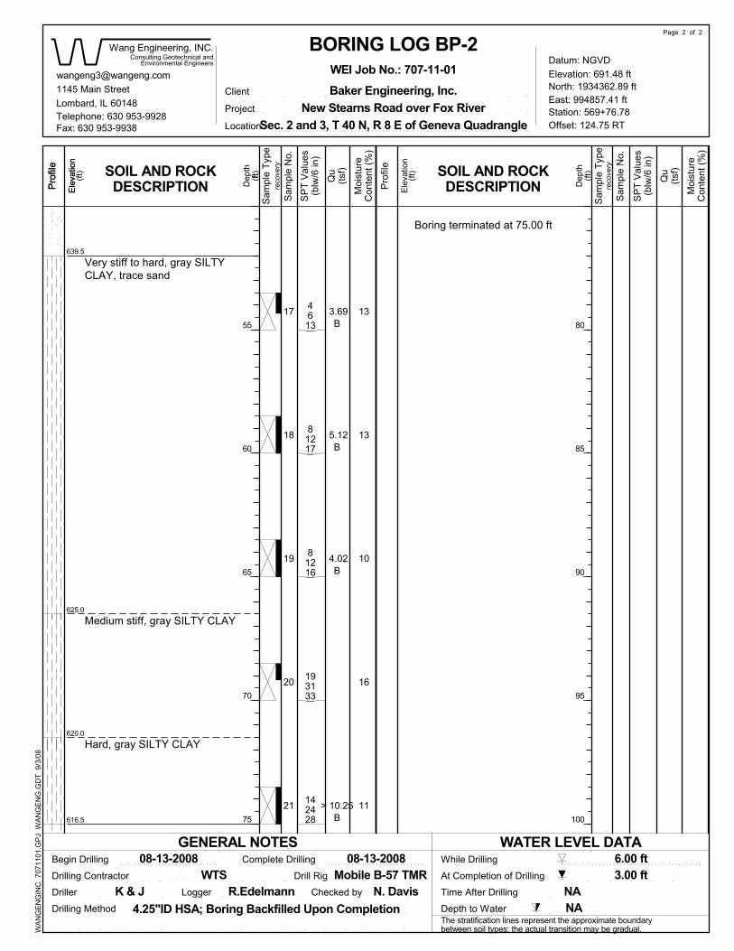
Fax: 630 953-9938
4.25"ID HSA; Boring Backfilled Upon Completion
Sam
ple
No.
Sam
ple
No.
Environmental Engineers
Depth to Water
Checked by
LocationTelephone: 630 953-9928
1145 Main Street
(blw
/6 in
)
Pro
file
55
60
65
70
75
Offset: 124.75 RT
Boring terminated at 75.00 ft
SOIL AND ROCKDESCRIPTIONE
leva
tion
Elevation: 691.48 ft
Project
(blw
/6 in
)
Mobile B-57 TMR
Consulting Geotechnical andP
rofil
e
Driller
Drilling Method
Baker Engineering, Inc.
Con
tent
(%)
(tsf)
11
Hard, gray SILTY CLAY
Medium stiff, gray SILTY CLAY
Very stiff to hard, gray SILTYCLAY, trace sand
616.5
620.0
639.5
16
10
13
13
625.0
> 10.25B
North: 1934362.89 ft
142428
193133
81216
81217
4613
21
20
19
17
4.02B
5.12B
3.69B
18
Ele
vatio
n
Lombard, IL 60148
Dep
th
6.00 ftBegin Drilling
(ft)
Sec. 2 and 3, T 40 N, R 8 E of Geneva Quadrangle
(tsf)
Pro
file
Station: 569+76.78
While Drilling
Drilling Contractor
East: 994857.41 ft
80
85
90
95
100
WA
NG
EN
GIN
C 7
0711
01.G
PJ
WA
NG
EN
G.G
DT
9/3
/08
ft
Sam
ple
Type
Dep
th
Moi
stur
e
08-13-2008
Client
Con
tent
(%)
WTS
(ft)
Time After Drilling
(ft)SOIL AND ROCK
DESCRIPTION
Sam
ple
Type
(ft)
Drill Rig
Datum: NGVD
reco
very
GENERAL NOTES
reco
very
WATER LEVEL DATA
Wang Engineering, INC.
08-13-2008
Ele
vatio
n
SP
T V
alue
s
SP
T V
alue
s
The stratification lines represent the approximate boundarybetween soil types; the actual transition may be gradual.
New Stearns Road over Fox River
Qu
N. DavisNA
3.00 ftAt Completion of Drilling
Moi
stur
e
Qu
Page 2 of 2
R.EdelmannK & J
WEI Job No.: 707-11-01
Logger
BORING LOG BP-2
Complete Drilling
NA
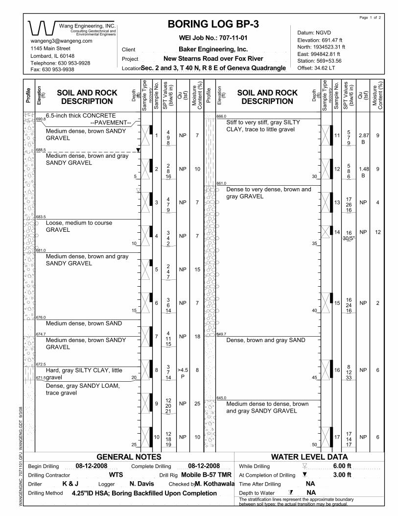
NP
NP
NP
NP
NP
NP
>4.5P
NP
NP
81233
NP
3714
16
17
498
2816
479
342
247
2.87B
41115
13
122021
121819
579
586
172616
1630/5"
162416
3614
5
NP
NP
NP
NP
1
2
15
414
6
7
8
9
10
11
12
3 4
15
7
18
8
25
10
7
910
12
2
6
6
690.8
688.5
683.5
9
7
674.7
7
681.0
Dense to very dense, brown andgray GRAVEL
Medium dense, brown and graySANDY GRAVEL
1.48B
672.5
671.5
666.0
661.0
649.7
645.0
Medium dense to dense, brownand gray SANDY GRAVEL
Medium dense, brown SANDYGRAVEL
Dense, brown and gray SAND
Loose, medium to courseGRAVEL
Medium dense, brown and graySANDY GRAVEL
Medium dense, brown SAND
Medium dense, brown SANDYGRAVEL
Hard, gray SILTY CLAY, littlegravelDense, gray SANDY LOAM,trace gravel
Stiff to very stiff, gray SILTYCLAY, trace to little gravel
676.0
6.5-inch thick CONCRETE--PAVEMENT--
GENERAL NOTES
Page 1 of 2
08-12-2008
New Stearns Road over Fox RiverClient
reco
very
Datum: NGVD
NP
(ft)
WEI Job No.: 707-11-01
BORING LOG BP-3
LoggerK & J NA
Sam
ple
Type
The stratification lines represent the approximate boundarybetween soil types; the actual transition may be gradual.
SP
T V
alue
s
SP
T V
alue
s
Ele
vatio
n
08-12-2008
Qu
Wang Engineering, INC.
WATER LEVEL DATA
reco
very
171417
Sam
ple
Type
N. Davis
6.00 ft
Dep
th
Ele
vatio
n
Dep
th
Moi
stur
e
(tsf)
(ft)
WTS
Con
tent
(%)
Lombard, IL 60148
(ft)
Moi
stur
e
At Completion of Drilling 3.00 ft
NAM. Kothawala
Qu
Time After Drilling
(ft)
East: 994842.81 ft
Drilling Contractor
While Drilling
Station: 569+53.56
Pro
file
1145 Main Street
(blw
/6 in
)
Offset: 34.62 LTTelephone: 630 953-9928
Location
Checked by
Depth to Water
Environmental Engineers
Sam
ple
No.
Pro
file
Consulting Geotechnical and
(tsf)
Con
tent
(%)
Baker Engineering, Inc.
Drilling Method
Driller
Sam
ple
No.
Fax: 630 953-9938
Pro
file
5
10
15
20
25
North: 1934523.31 ftE
leva
tion
SOIL AND ROCKDESCRIPTION
Mobile B-57 TMR
Elevation: 691.47 ft
Sec. 2 and 3, T 40 N, R 8 E of Geneva Quadrangle
4.25"ID HSA; Boring Backfilled Upon Completion
Complete Drilling
WA
NG
EN
GIN
C 7
0711
01.G
PJ
WA
NG
EN
G.G
DT
9/3
/08
SOIL AND ROCKDESCRIPTION
ft
Drill Rig
Begin Drilling
30
35
40
45
50
Project
(blw
/6 in
)
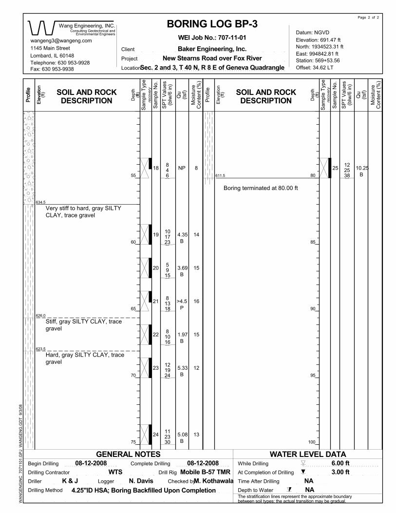
22
55
60
65
70
75
Pro
file
122538
112330
121924
81016
81318
5915
101723
846
25
24
Pro
file
Consulting Geotechnical and
Begin Drilling
Driller
Drilling Method
Baker Engineering, Inc.
Con
tent
(%)
(tsf)
1145 Main Street
21
Sam
ple
No.
Sam
ple
No.
Depth to Water
Boring terminated at 80.00 ft
LocationTelephone: 630 953-9928
Offset: 34.62 LT
(blw
/6 in
)
Fax: 630 953-9938
16
23
Hard, gray SILTY CLAY, tracegravel
Stiff, gray SILTY CLAY, tracegravel
Very stiff to hard, gray SILTYCLAY, trace gravel
611.5
623.5
626.0
634.5
13
15
15
14
8
12
20
19
18 10.25B
5.08B
5.33B
1.97B
>4.5P
3.69B
4.35B
Environmental Engineers
NP
Dep
th
6.00 ft
Time After DrillingChecked by
Ele
vatio
n
M. Kothawala
Pro
file
Station: 569+53.56
While Drilling
Drilling Contractor
East: 994842.81 ft
(ft)
(ft)
Qu
[email protected]: 1934523.31 ft
08-12-2008
80
85
90
95
100
WA
NG
EN
GIN
C 7
0711
01.G
PJ
WA
NG
EN
G.G
DT
9/3
/08
ft
Sam
ple
Type
Lombard, IL 60148Client
Con
tent
(%)
WTS
(ft)
(tsf)
Moi
stur
e
Dep
th
Wang Engineering, INC.
reco
very
SP
T V
alue
s
SP
T V
alue
s
Ele
vatio
n
08-12-2008Drill Rig
SOIL AND ROCKDESCRIPTION
WATER LEVEL DATA
New Stearns Road over Fox River
Ele
vatio
n
Mobile B-57 TMR
(blw
/6 in
)
Project
The stratification lines represent the approximate boundarybetween soil types; the actual transition may be gradual.
Elevation: 691.47 ft
reco
verySOIL AND ROCK
DESCRIPTION
4.25"ID HSA; Boring Backfilled Upon Completion
Sec. 2 and 3, T 40 N, R 8 E of Geneva Quadrangle
Complete Drilling
N. Davis
(ft)
GENERAL NOTES
WEI Job No.: 707-11-01
BORING LOG BP-3
Sam
ple
Type
NALogger
Page 2 of 2
Qu
Moi
stur
e
At Completion of Drilling 3.00 ft
NAK & J
Datum: NGVD
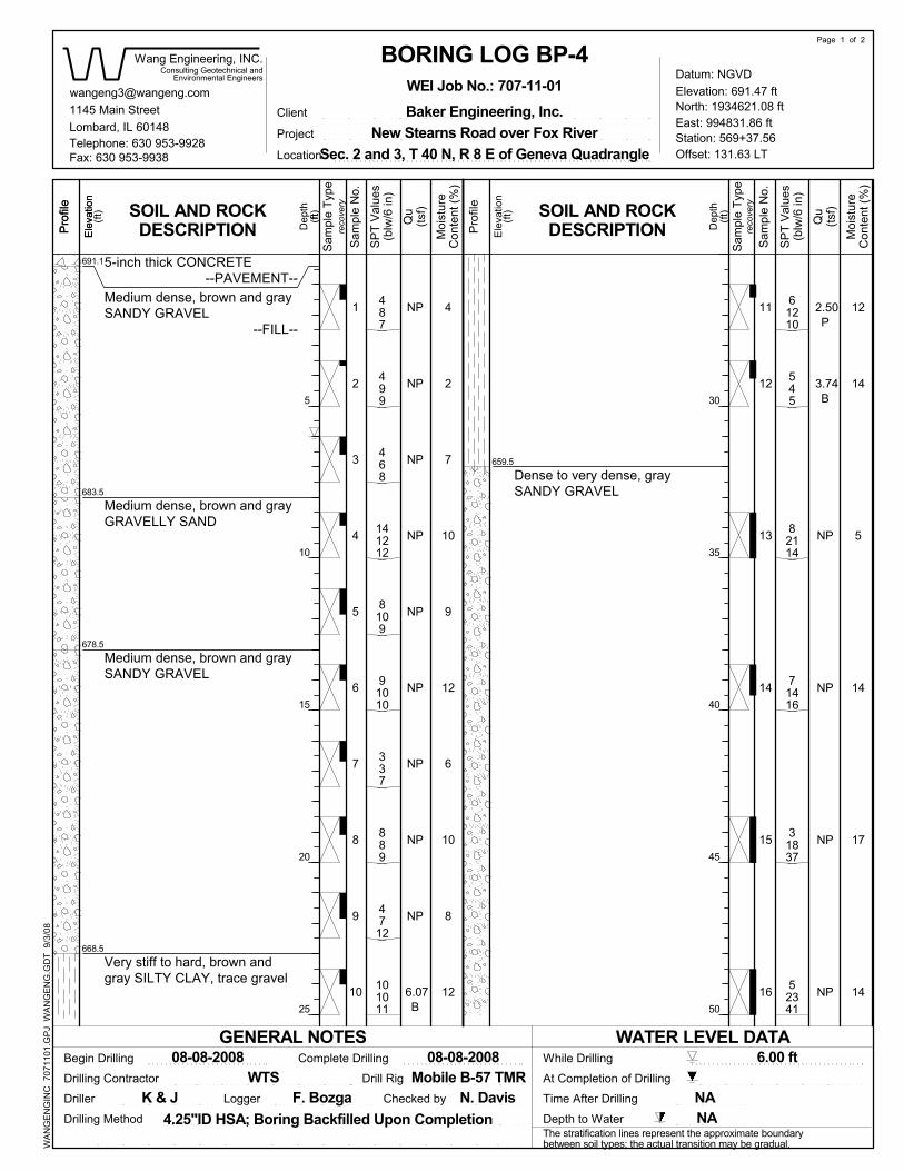
Qu
NAN. DavisNA
At Completion of Drilling
Moi
stur
e
Qu
Page 1 of 2
F. Bozga
13
Station: 569+37.56
While Drilling
Drilling Contractor
East: 994831.86 ft
(ft)
(ft)
NP
NP
1
2
3
NP
5
3.74B
7
9
10
11
12
4
NP
K & J
NP
NP
NP
NP
Pro
file
NP
NP
NP
NP
6.07B
2.50P
NP
14
678.5
9
12
6
10
8
7
12
2
5
14
17
14
691.1
12
10
668.5
4
683.5
Dep
th
6.00 ft
Lombard, IL 60148
Time After Drilling
Ele
vatio
n
659.5
5-inch thick CONCRETE--PAVEMENT--
Medium dense, brown and graySANDY GRAVEL
--FILL--
Medium dense, brown and grayGRAVELLY SAND
Medium dense, brown and graySANDY GRAVEL
Very stiff to hard, brown andgray SILTY CLAY, trace gravel
8
Dense to very dense, graySANDY GRAVEL
reco
very
Ele
vatio
n
08-08-2008
Wang Engineering, INC.
SP
T V
alue
s
WATER LEVEL DATA
The stratification lines represent the approximate boundarybetween soil types; the actual transition may be gradual.
New Stearns Road over Fox River
reco
very
Datum: NGVD
Mobile B-57 TMR
4.25"ID HSA; Boring Backfilled Upon Completion
(blw
/6 in
)
Project
14
Elevation: 691.47 ft
SP
T V
alue
s
SOIL AND ROCKDESCRIPTION
Sam
ple
Type
Sec. 2 and 3, T 40 N, R 8 E of Geneva Quadrangle
Complete Drilling
SOIL AND ROCKDESCRIPTION
Drill Rig
6
08-08-2008
Con
tent
(%)
ft
WA
NG
EN
GIN
C 7
0711
01.G
PJ
WA
NG
EN
G.G
DT
9/3
/08
30
35
40
45
50
Sam
ple
Type
Dep
th(ft
)
GENERAL NOTES
WEI Job No.: 707-11-01
BORING LOG BP-4
Logger
Client
Moi
stur
e
(tsf)
(ft)
WTS
31837
71416
Ele
vatio
n
North: 1934621.08 ft
337
15
16
487
499
468
141212
52341
91010
889
4712
101011
61210
545
82114
8109
Sam
ple
No.
Consulting Geotechnical and
Begin Drilling
1145 Main Street
Sam
ple
No.
(tsf)
Con
tent
(%)
Driller
Baker Engineering, Inc.
Drilling Method
Fax: 630 953-9938
5
10
15
20
25
Pro
file
Pro
file
Environmental Engineers
(blw
/6 in
)
Offset: 131.63 LTTelephone: 630 953-9928
Location
Checked by
Depth to Water
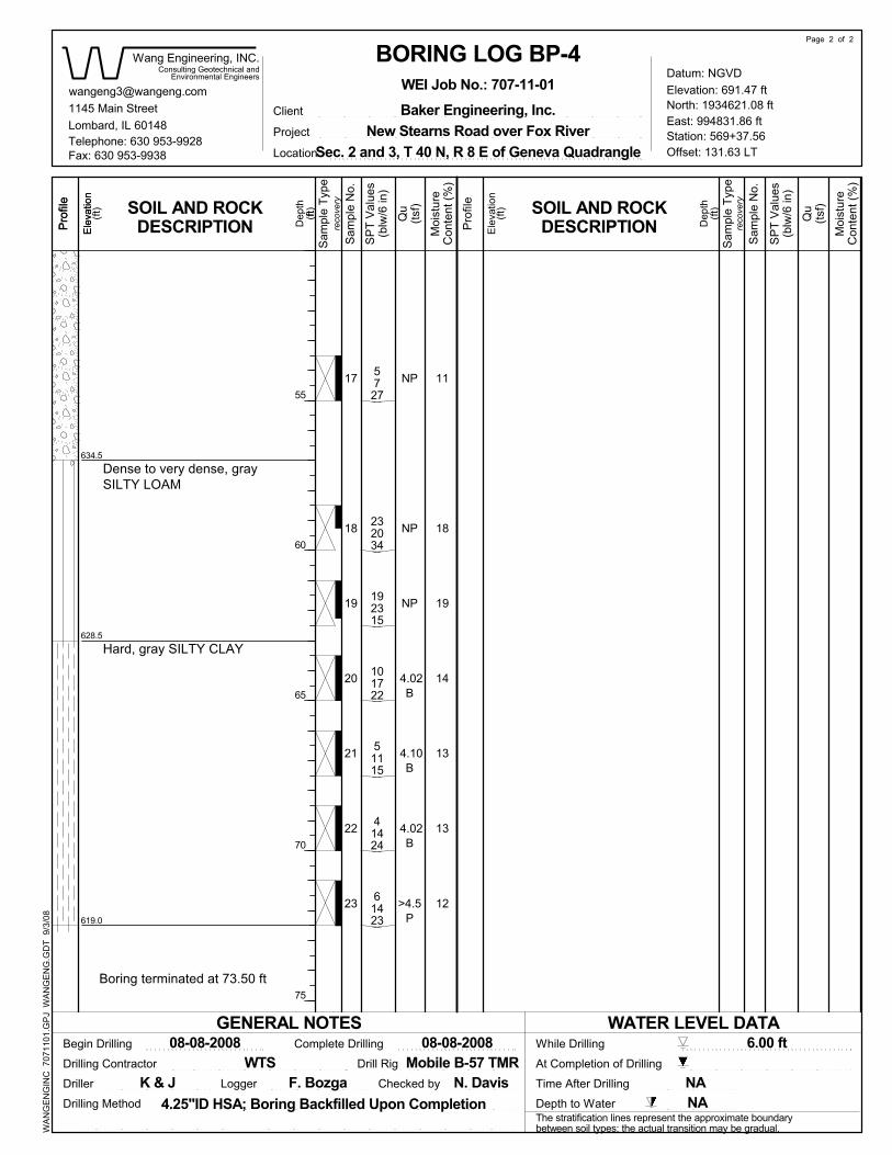
232034
(blw
/6 in
)
Fax: 630 953-9938
Pro
file
55
60
65
70
75
Telephone: 630 953-9928Location
61423
41424
51115
101722
Mobile B-57 TMR
North: 1934621.08 ft
Pro
file
Begin Drilling
Driller
Drilling Method
Baker Engineering, Inc.
Offset: 131.63 LT
(tsf)
5727
WA
NG
EN
GIN
C 7
0711
01.G
PJ
WA
NG
EN
G.G
DT
9/3
/08
1145 Main Street
Boring terminated at 73.50 ft
Sam
ple
No.
Sam
ple
No.
Environmental Engineers
Depth to Water
Checked by
Con
tent
(%)
14
192315
Hard, gray SILTY CLAY
Dense to very dense, graySILTY LOAM
619.0
628.5
634.5
12
13
19
18
11
13
NP
23
22
21
20
19
18
17
>4.5P
4.02B
4.02B
NP
NP
4.10B
Station: 569+37.56
6.00 ft
Time After Drilling
Consulting Geotechnical and
Ele
vatio
n
(blw
/6 in
)
N. Davis
Lombard, IL 60148
While Drilling
Drilling Contractor
East: 994831.86 ft
(ft)
(ft)
Qu
Pro
file
Con
tent
(%)
ft
Sam
ple
Type
08-08-2008
Dep
th
WTS
(ft)
(tsf)
Moi
stur
e
Dep
th
Client
reco
very
Elevation: 691.47 ft
4.25"ID HSA; Boring Backfilled Upon Completion
Ele
vatio
n
SOIL AND ROCKDESCRIPTION
WATER LEVEL DATA
New Stearns Road over Fox River
08-08-2008
Ele
vatio
n
SP
T V
alue
s
SP
T V
alue
s
The stratification lines represent the approximate boundarybetween soil types; the actual transition may be gradual.
Drill Rig
SOIL AND ROCKDESCRIPTION
Complete Drilling
Sec. 2 and 3, T 40 N, R 8 E of Geneva Quadrangle
Wang Engineering, INC.
(ft)
NA
At Completion of Drilling
Moi
stur
e
Qu
Page 2 of 2
F. Bozga NAK & J Logger
BORING LOG BP-4WEI Job No.: 707-11-01
GENERAL NOTES
reco
very
Project
Sam
ple
Type
Datum: NGVD
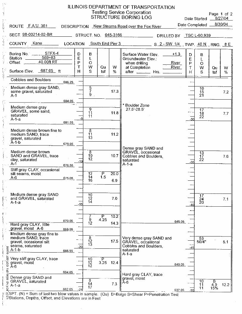
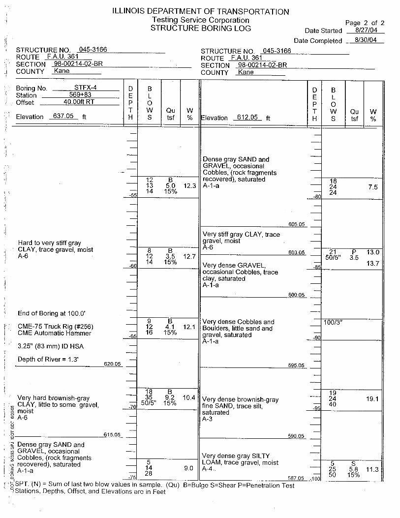
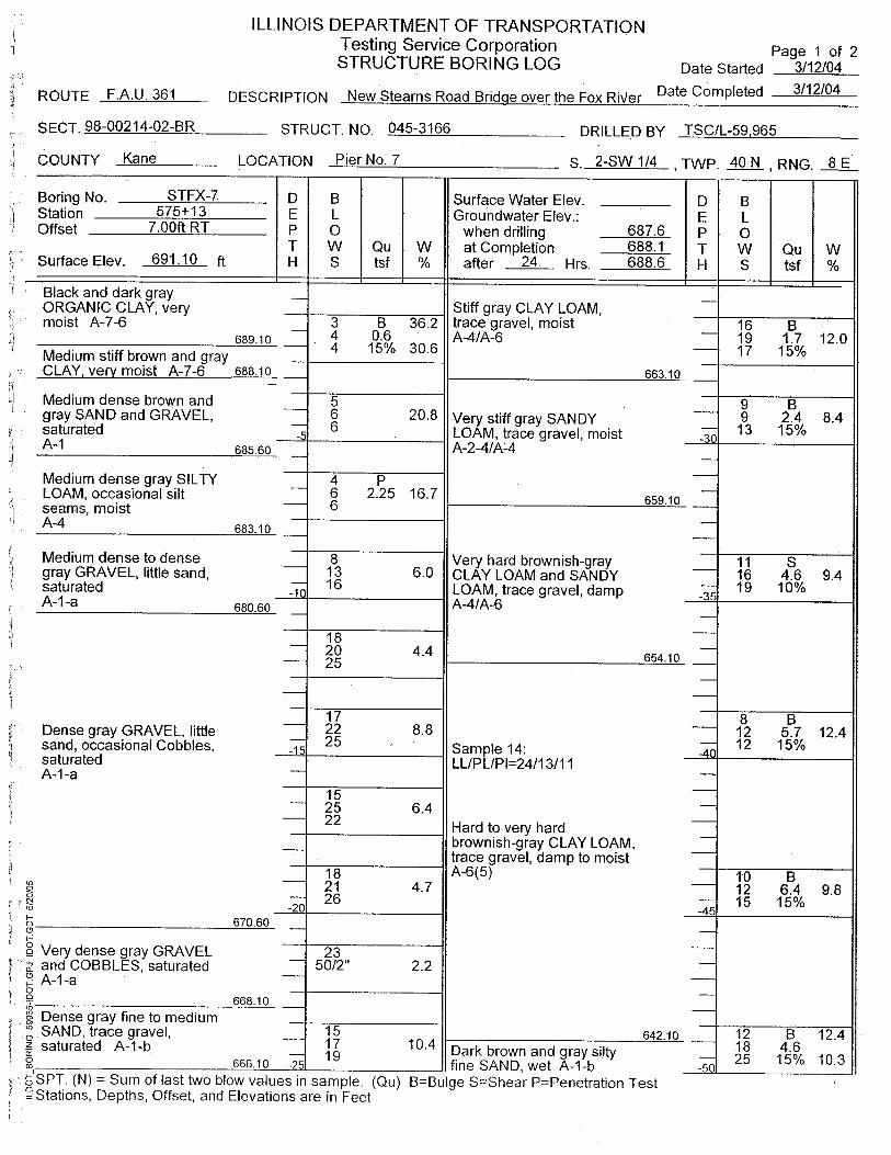
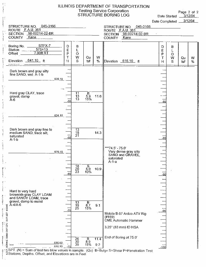
APPENDIX B
Geotechnical • Construction • Environmental Quality Engineering Services Since 1982
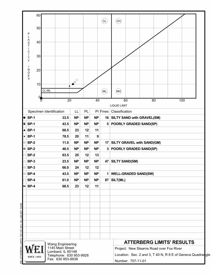
LL
43.5
PI
BP-4
BP-4
BP-4
BP-3
Specimen Identification
66.0
23.5
63.5
48.5
11.0
78.5
68.5
68.5
PL
BP-3
33.5
ATTERBERG LIMITS' RESULTS
43.5
61.0
10
0
BP-1
40
80
BP-2
BP-2
BP-1
BP-1
BP-1
20
100
30
6040200
60
50
BP-2
11
NP
NP
12
NP
NP
12
NP
12
9
NP NP
12
NP
NP
23
NP
NP
24
NP
25
NP
SILTY GRAVEL with SAND(GM)
Project: New Stearns Road over Fox River
Location: Sec. 2 and 3, T 40 N, R 8 E of Geneva Quadrangle
Number: 707-11-01
Wang Engineering1145 Main StreetLombard, IL 60148Telephone: 630 953-9928Fax: 630 953-9938
SILT(ML)
WELL-GRADED SAND(SW)
11
POORLY GRADED SAND(SP)
20
POORLY GRADED SAND(SP)
SILTY SAND with GRAVEL(SM)
11
NP
NP
12
NP
13
NP
SILTY SAND(SM)
LIQUID LIMIT
PLASTICITY
INDEX
CL-ML
NP
ClassificationFines
WE
I_A
TTE
RB
ER
G_L
IMIT
S 7
0711
01.G
PJ
US
_LA
B.G
DT
9/2
/08
23
NP
NP
87
1
47
3
17
16
CH
MH
CL
ML
NP
5
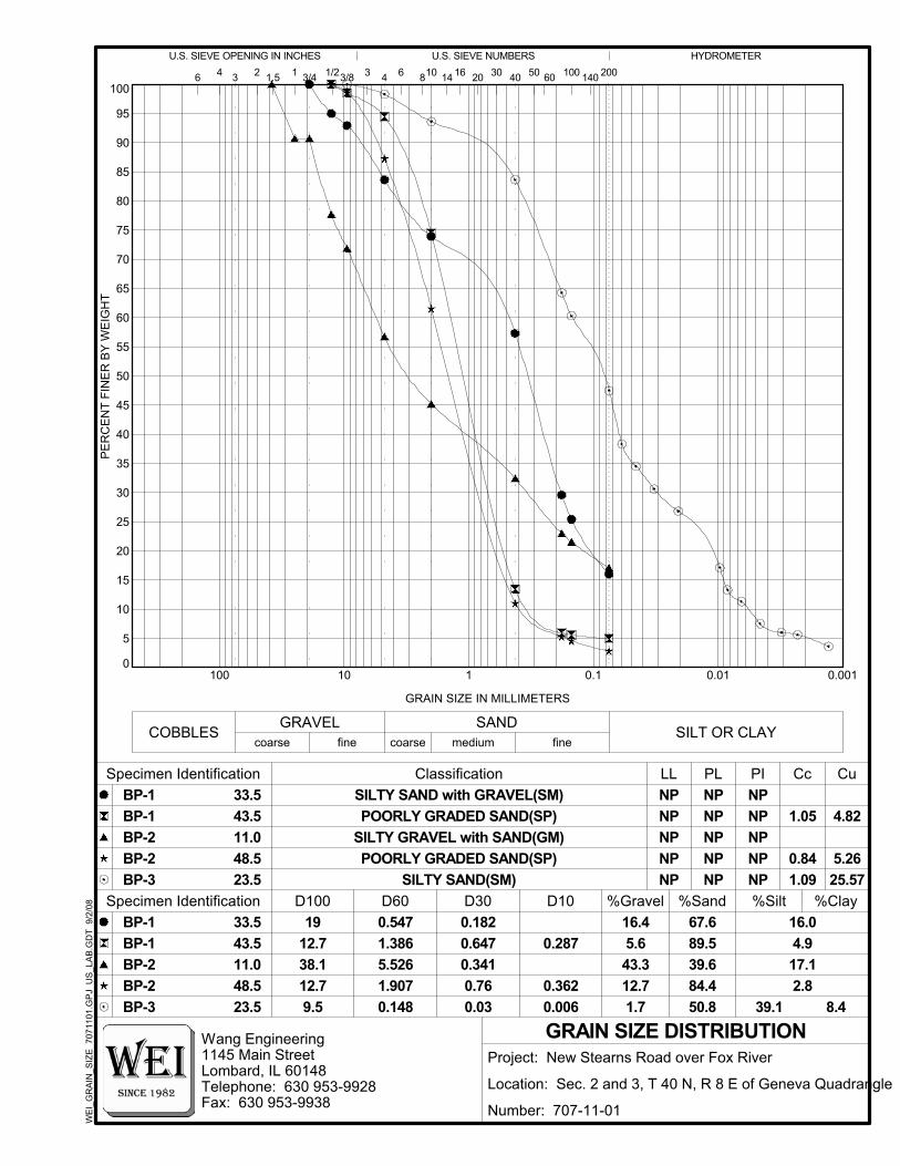
14108
GRAIN SIZE DISTRIBUTION
Cc
Cu
23.548.511.043.533.5
PI
100
0
5
10
15
25
95
90
85
80
75
70
65
60
55
50
45
40
35
20
30
100 10 1 0.1 0.01 0.001
30
NP
SILTY SAND(SM)
Classification33.543.511.048.523.5
SILTY GRAVEL with SAND(GM)
20
POORLY GRADED SAND(SP)
40 501.5
U.S. SIEVE OPENING IN INCHES U.S. SIEVE NUMBERS16
0.362
1912.738.112.79.5
0.1820.6470.3410.76
POORLY GRADED SAND(SP)
0.287
NP
0.006
200
D100 D60
6
SILTY SAND with GRAVEL(SM)
0.03
PE
RC
EN
T FI
NE
R B
Y W
EIG
HT
NP
89.539.684.450.8 39.1
0.5471.3865.526
0.148
Wang Engineering1145 Main StreetLombard, IL 60148Telephone: 630 953-9928Fax: 630 953-9938
Project: New Stearns Road over Fox River
Location: Sec. 2 and 3, T 40 N, R 8 E of Geneva Quadrangle
Number: 707-11-01
1.907
NPNPNP
NPNPNPNPNP
NPNP
67.6
NP
GRAIN SIZE IN MILLIMETERS
16.04.917.12.8
8.4
NPBP-2BP-2BP-3
100 1403 2
BP-1
%Clay
COBBLESGRAVEL SAND
SILT OR CLAY
4
BP-1BP-1BP-2BP-2
4
Specimen Identification
Specimen Identification D30
BP-1
D10
PL
1 3/4 1/23/8 3
%Gravel %Sand %Silt
HYDROMETER
60
fine
BP-3
coarse fine coarse medium
6W
EI_
GR
AIN
_SIZ
E 7
0711
01.G
PJ
US
_LA
B.G
DT
9/2
/08
0.84
4.82
5.2625.57
16.45.643.312.7
1.05
1.09
LL
1.7
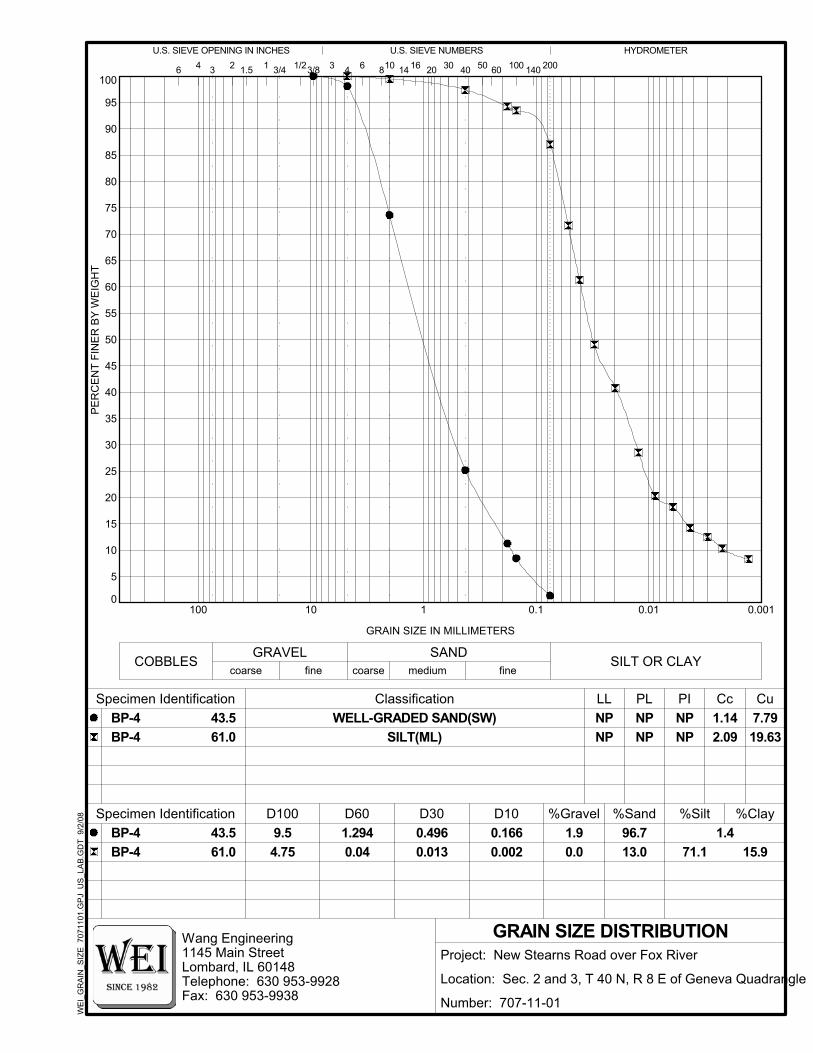
Cc
GRAIN SIZE DISTRIBUTION
PI
Cu
43.5
0.1
61.0
10
5
65
10
1
14
0.01 0.001
100
95
90
85
80
70
0
60
55
50
45
40
35
30
25
20
15
10
100
75
Classification
D100 D60
6
WELL-GRADED SAND(SW)
8
0.002
43.561.0
16 20 30 40
SILT(ML)
coarse fine coarse medium
6
GRAIN SIZE IN MILLIMETERS
200
9.54.75
0.4960.013
0.166
1.5 50
96.713.0 71.1
1.2940.04
Wang Engineering1145 Main StreetLombard, IL 60148Telephone: 630 953-9928Fax: 630 953-9938
Project: New Stearns Road over Fox River
Location: Sec. 2 and 3, T 40 N, R 8 E of Geneva Quadrangle
Number: 707-11-01
PE
RC
EN
T FI
NE
R B
Y W
EIG
HT
NP
U.S. SIEVE OPENING IN INCHES U.S. SIEVE NUMBERS
NPNPNPNP
1.415.9
NPBP-4
3/8 3
%Gravel %Sand %Silt
3/4
BP-4
1 100 1403 2
%Clay
Specimen Identification
Specimen Identification
1/2
D30
COBBLES
D10
4
60
fine
WE
I_G
RA
IN_S
IZE
707
1101
.GP
J U
S_L
AB
.GD
T 9
/2/0
8
GRAVEL SANDSILT OR CLAY
4
BP-4BP-4
PL
HYDROMETER
7.7919.63
1.90.0
1.142.09
LL

Geotechnical • Construction • Environmental Quality Engineering Services Since 1982


![SERVANT - sgr-store.com1].pdf · 2019 SGR SERVANT LEADERSHIP CONFERENCE. TABLE OF . CONTENTS. 2019 SGR SERVANT LEADERSHIP CONFERENCE PACIFIC NORTHWEST. 2019_SGR_Conference_PNW_Guide.](https://static.fdocuments.us/doc/165x107/5f5a796013ea3c79ea64a464/servant-sgr-storecom-1pdf-2019-sgr-servant-leadership-conference-table-of.jpg)