Final SAF Report (1)
48
AJAY KUMAR GARG ENGINEERING COLLEGE A Training Report On Small arms manufacturing at Indian ordnance-Small arms factory, Kanpur GUIDED BY: SUBMITTED BY: S.K. CHAUDHARI ANKITA TRIPATHI JR. WORK MANAGER 4 th YEAR
-
Upload
siddharth-garkhail -
Category
Documents
-
view
616 -
download
5
Transcript of Final SAF Report (1)

AJAY KUMAR GARG ENGINEERING COLLEGE
A Training Report
On
Small arms manufacturing
at
Indian ordnance-Small arms factory, Kanpur
GUIDED BY: SUBMITTED BY:
S.K. CHAUDHARI ANKITA TRIPATHI
JR. WORK MANAGER 4th YEAR
FOR GENERAL MANAGER MECHANICAL ENGG 0802740019
AJAY KUMAR GARG ENGINEERING COLLEGE 27th Km stone, Delhi Hapur Bypass Road, P.O.Adhyatmik Nagar ,Ghaziabad-201009
TRAINING CERTIFICATE
This is to certify that ANKITA TRIPARHI, student of Ajay Kumar Garg Engineering College, Ghaziabad, who is presently in 4th
year of B.Tech (Mechanical Engineering), has undergone vocational training at INDIAN ORDNANCE FACTORY-SMALL ARMS FACTORY, KANPUR from 16th June 2011 to 15th July 2011.
I.P.SHARMA GP.CAPT.P.K.CHOPRA
HOD DEPARTMENT VSM (Retd.)
Prof. & HOD (T&P)

Acknowledgment Summer training in INDIAN ORDNANCE-SMALL ARMS FACTORY was a learning experience for me. Working in such an encouraging atmosphere with the people dealing with latest technology, working in tight schedule, dedicated to work and ready to help is privilege.
Working in different shops provide a real time experience of engineering and technology being used, currently, in manufacturing industry..
I would like to thank Mr. S.K.CHAUDHARI who allowed & made complete arrangement for this training. I am heartily grateful to Mr. B.N.MUKHEJI(TOOL ROOM), Mr.D.S.RATHORE (CNC SECTION) , Mr. S.K. MISHRA (BARREL SECTION), Mr.RAKESH VERMA (RCS SECTION) and Mr. D.N. TRIPATHI (HT SECTION) who gave me such affection,guidance and support for completing this training and making this report.
ANKITA TRIPATHI

PREFACE
The report on the following pages is the outcome of four weeks training at the industry.
The report is the outcome of the practical knowledge that we acquire during our training. This report presents the brief summary of our industrial training.
I had the privilege of receiving such training at
INDIAN ORDNANCE- SMALL ARMS FACTORY, KANPUR.
There could not be a better place to learn…

TABLE OF CONTENTS
ORDNANCE FACTORY INTRODUCTION GEOGRAPHICAL SPREAD SMALL ARMS FACTORY-COMPANY
PROFILE PRODUCTS OF SAF-KANPURDEPARTMENTS
MAIN COMPONENTS OF GUN MACHINARY AND INDUSTRIAL
EQUIPMENTSVARIOUS TOOLSSTUDY OF VARIOUS MACHINES
HEAT TREATMENT PROCESSES
INDIAN ORDNANCE FACTORY
INTRODUCTION:
HISTORY:
The history and development of Indian Ordnance Factories is directly linked with the British reign in India. East India company of England for their economic interest in India and to increase their political hold considered military hardware as vital element. During 1775 British authorities accepted the establishment of Board of Ordnance in Fort William, Kolkata. This marks the official beginning of the Army Ordnance in India. In 1787 a gun powder factory was established at Ishapore which started production from 1791 ( at which location Rifle Factory was established in 1904). In 1801 a Gun Carriage Agency at Cossipore, Kolkata (presently known as Gun & Shell Factory, Cossipore) was eatablished and production started from 18th March, 1802. This is the first Industrial establishment of Ordnance Factories which has continued its existence till date.
Growth of Indian Ordnance Factories
The growth of the Ordnance Factories leading to its present setup has been continuous but in spurts. There were 18 ordnance factories before India became independent in 1947. 21 factories have been established after independence - mostly, in wake of defence preparedness imperatives caused by the three major wars fought by the Indian Armed forces. 40th Factory is under establishment at Nalanda, Bihar.

Geographical Spread
There are 39 Ordnance Factories geographically distributed all over the country at 24 different locations.
Name of State/ Union Territory Number of factories
Maharashtra 10
Uttar Pradesh 8
Madhya Pradesh 6
Tamil Nadu 6
West Bengal 4
Uttaranchal 2
Andhra Pradesh 1
Chandigarh 1
Orissa 1
The 40th Factory is being set up at Nalanda in Bihar.
Factories
1. Ammunition Factory Khadki (AFK)2. Cordite Factory Aruvankadu (CFA)3. Engine Factory Avadi (EFA)4. Field Gun Factory Kanpur (FGK)5. Gun Carriage Factory (GCF)6. Grey Iron Foundry (GIF)7. Gun and Shell Factory (GSF)8. Heavy Alloy Penetrator Project (HAPP)9. High Explosive Factory (HEF)10.Heavy Vehicle Factory (HVF)11.Machine Tool Prototype Factory (MPF)12.Metal and Steel Factory (MSF)13.Ordnance Clothing Factory Avadi (OCFAV)

14.Ordnance Cable Factory Chandigarh (OCFC)15.Ordnance Clothing Factory Shahjahanpur (OCFS)16.Ordnance Equipment Factory Kanpur (OEFC)17.Ordnance Equipment Factory Hazratpur (OEFHZ)18.Ordnance Factory Ambernath (OFA)19.Ordnance Factory Ambajhari (OFAJ)20.Ordnance Factory Bhandara (OFBA)21.Ordnance Factory Bhusawal (OFBH)22.Ordnance Factory Bolangir (OFBOL)23.Ordnance Factory Kanpur (OFC)24.Ordnance Factory Chandrapur (OFCH)25.Ordnance Factory Dumdum (OFDC)26.Ordnance Factory Dehu Road (OFDR)27.Ordnance Factory Dehradun (OFDUN)28.Ordnance Factory Itarsi (OFI)29.Ordnance Factory Khamaria (OFK)30.Ordnance Factory Katni (OFKAT)31.Ordnance Factory Muradnagar (OFM)32.Ordnance Factory Project Nalanda (OFN)33.Ordnance Factory Project Medak (OFPM)34.Ordnance Factory Tiruchirapalli (OFT)35.Ordnance Factory Varangaon (OFV)36.Opto Electronics Factory (OLF)37.Ordnance Parachute Factory (OPF)38.Rifle Factory Ishapore (RFI)39.Small Arms Factory (SAF)40.Vehicle Factory Jabalpur (VFJ)

SMALL ARMS FACTORY,KANPURSAF was built in 1942 as part of the strategic plan to have a shadow factory of RFI at Kanpur to undertake manufacture of small arms as a sequel to threat on the eastern border during world war-II.
· The factory was known as Transplantation Project -1.
· After independence, the factory was renamed as Small Arms Factory in the year 1949.
· SAF is engaged in consistently supplying small arms to MOD & Paramilitary forces.
· Manufacturing facilities built over an area of 103 acres.
· The organization possess highly skilled, qualified and dedicated team of 2200 personnel.
Small arms are a term of art used by armed forces to denote infantry weapons an individual soldier may carry.

The description is usually limited to revolvers, pistols, submachine guns, carbines, assault rifles, battle rifles, multiple barrel firearms, sniper rifles, squad automatic weapons, light machine guns, and sometimes hand grenades. Shotguns, general purpose machine guns, medium machine guns, and grenade launchers may be considered small arms or as support weapons, depending on the particular armed forces.
PRODUCTS OF SAF,KANPUR

LMG 5.56mm Rifle 5.56mm Amogh 5.56mm Carbine MAC gun Assault rifle 7.62mm Revolver
MAIN DEPARTMENTS OF SAF, KANPUR
Whole working system of SAF, Kanpur can be categories in two systems having various departments of the factory:
1) Management system : it includes various departments
Admin Record keeping Promotion and punishments Wages / salary Hospital Canteen Welfare Purchase Store Working condition Recruitments and training
2) Engineering system :
Production planning Quality control Machinery planning Tooling Process planning Material handling
Engineering system may also classified as productive departments and non productive.

Production departments included IA , SC , CNC, TR, HT , RCS , MCS. Store and maintenance sections come under non- production departments.
MAIN COMPONENTS OF GUN

Barrel
The barrel is a tube which the bullet is projected. The pressure of gases driving a rifle bullet can reach about fifty thousand pounds per square inch (3333 bar) and temperature 3500 degrees Fahrenheit (2200 C) in the barrel. These rise and fall during the few milliseconds (thousandths of seconds) when the projectile is in the barrel. So both thermal and mechanical stresses affect the barrel. Formulas which describe gas pressure and projectile position and velocity have been determined experimentally, for example Leduc’s method. Pistol and shotgun rounds operate at considerably lower pressures than rifle rounds at approximately one third.
As described above, barrels are usually rifled since the spin imparted by the rifling stabilizes the projectile in flight, decreasing wind deflection, and increasing aerodynamic stability. Exceptions include shotguns which fire a collection of projectiles with each shot, and anti-armour guns which fire light, high-velocity sub-calibre rounds. The latter are usually fired from tanks with smooth bore barrels (barrels with no rifling).
The latter are usually surrounded by a sabot while in the barrel. The increased bore diameter occupied by the sabot means pressure is applied over a larger surface area, resulting in a higher velocity. The sabot falls away after the projectile leaves the barrel. The smaller projectile also has less frontal area to be affected by aerodynamic drag and travels more efficiently to target. Sabot slugs and bullets are sometimes used in rifles, shotguns, and black powder small arms.
Chamber
The chamber is the portion of the barrel or barrel extension which supports the cartridge case while it is in firing position.

Trigger
The trigger is the user interface to the firing assembly. It can be activated by finger pressure, or it can be an electro-mechanical device. In some systems the entire firing chain is electrical, for example in most 20mm and larger cannon and a few .22 rim fire competition rifles. In those systems the trigger is a switch or electrical relay.
Sear
The sear is the portion of the trigger mechanism which directly holds and releases the bolt or striker. It interfaces directly or indirectly with the trigger.
Striker (Firing Pin)
The striker is usually a small rod or hammer which impacts the primer of the cartridge, setting off its percussion-sensitive charge and beginning the propellant ignition chain. The striker assembly sometimes consists of multiple moving parts such as a hammer which hits a transfer bar or firing pin. Strikers are sometimes implemented as firing pins. The more generic term striker is generally used here.

Receiver
The receiver is the body or frame of the gun to which the barrel, ammunition feeding devices, stocks or handles attach, and in which bolt operates. The bolt often rides on rails, rods, or recesses in the receiver. The receiver is sometimes divided into separate assemblies to facilitate cleaning, stoppage clearing, or other operational issues. The receiver and operating parts inside are also called the action.
The receiver can be made from stamped sheet metal, cast and/or machined metal, high-technology plastics, or combinations thereof. One of the most successful applications of a plastic receiver is the frame of the Glock pistol. The frame has carbide (very hard metal) guides molded into it. The Glock's slide (bolt) is conventional tool steel with a high-tech subsurface finish.
Bolt (Breech)
The bolt or breech constrains the cartridge in such a way that high pressure gases generated upon firing are kept in the chambered case and barrel. This allows pressure to fall to safe levels before the action is opened to load the next round or stop firing. The Operating Systems section describes various ways this can happen.
Bolt Carrier
Especially in designs which use rotary locking, the bolt and bolt carrier can be separate objects. The bolt engages locking lugs in the receiver or chamber and the bolt carrier holds the bolt. Different methods of accomplishing this are described in the next Functions section. The bolt carrier is usually larger and more massive than the bolt.

MACHINARY AND INDUSTRIAL EQUIPMENTSVarious sections are equipped with suitable related machines, some of them are process control machines, some are metal cutting machines, testing and measuring machines .Some of them are CNC and NC machines. Various tools are used for different purposes. In tool room and meteorology section various gauges are manufactured and tested.
VARIOUS TOOLS
MILLING CUTTERSMilling cutters are cutting tools used in milling machines or machining centres. They remove material by their movement within the machine (eg: a ball nose mill) or directly from the cutters shape (a form tool such as a Hobbing cutter).

Features of a milling cutter
AN END MILL CUTTER WITH TWO FLUTES
Milling cutters come in several shapes and many sizes. There is also a choice of coatings, as well as rake angle and number of cutting surfaces.
END MILL
SLOT, END MILL, AND BALLNOSE CUTTERS
End mills (middle row in image) are those tools which have cutting teeth at one end, as well as on the sides. They are usually made from high speed steel (HSS) or carbide, and have one or more flutes. They are the most common tool used in a vertical mill.
SLOT DRILL
Slot drills (top row in image) are generally two (occasionally three or four) fluted cutters that are designed to drill straight down into the material. This is possible because there is at least one tooth at the centre of the end face. They are so named for their use in cutting keyway slots.
ROUGHING END MILL
Roughing end mills quickly remove large amounts of material. This kind of end mill utilizes a wavy tooth form cut on the periphery. These wavy teeth form many successive cutting edges producing many small chips, resulting in a relatively rough surface finish. During cutting, multiple teeth are in contact with the workpiece reducing chatter and vibration.
BALL NOSE CUTTER
Ball nose cutters (lower row in image) are similar to slot drills, but the ends of the cutters are hemispherical. They are ideal for machining 3-dimensional contoured shapes in machining centres, for example in moulds and dies.
SLAB MILL
HSS SLAB MILL
Slab mills are used either by themselves or in gang milling operations on manual horizontal or universal milling machines to machine large broad surfaces quickly. They have been superseded by the use of carbide-tipped face mills which are then used in vertical mills or machining centres.

SIDE-AND-FACE CUTTER
SIDE AND FACE CUTTER
The side-and-face cutter is designed with cutting teeth on its side as well as its circumference. They are made in varying diameters and widths depending on the application. The teeth on the side allow the cutter to make unbalanced cuts (cutting on one side only) without deflecting the cutter as would happen with a slitting saw or slot cutter (no side teeth).
FACE MILL
CARBIDE TIPPED FACE MILL
A face mill consists of a cutter body (with the appropriate machine taper) that is designed to hold multiple disposable carbide or ceramic tips or inserts, often golden in colour. The tips are not designed to be resharpened and are selected from a range of types that may be determined by various criteria, some of which may be: tip shape, cutting action required, and material being cut. When the tips are blunt, they may be removed, rotated (indexed) and replaced to present a fresh, sharp face to the workpiece, this increases the life of the tip and thus their economical cutting life.

DRILL BITDrill bits are cutting tools used to create cylindrical holes. Bits are held in a tool called a drill, which rotates them and provides torque and axial force to create the hole. Specialized bits are also available for non-cylindrical-shaped holes.
This article describes the types of drill bits in terms of the design of the cutter. The other end of the drill bit, the shank, is described in the drill bit shank article. Drill bits come in standard sizes, described in the drill bit sizes article.
The term drill can refer to a drilling machine, or can refer to a drill bit for use in a drilling machine. In this article, for clarity, drill bit or bit is used throughout to refer to a bit for use in a drilling machine, and drill refers always to a drilling machine.
VARIOUS DRILL BITS (TOP TO BOTTOM): SPADE, LIP AND SPUR (BRAD POINT), MASONRY BIT, TWIST DRILL
CENTER DRILL AND SPOTTING DRILL

CENTER DRILLS, NUMBERS 1 THROUGH TO 6
Centre drill bits are used in metalworking to provide a starting hole for a larger-sized drill bit or to make a conical indentation in the end of a work piece in which to mount a lathe centre. In either use, the name seems appropriate, as the drill is either establishing the centre of a hole or making a conical hole for a lathe centre.
Use in making holes for lathe centres
Centre drills are meant to create a conical hole for "between centres" manufacturing processes (typically lathe or cylindrical-grinder work). That is, they provide a location for a (live, dead, or driven) centre to locate the part about an axis. A work piece machined between centres can be safely removed from one process (perhaps turning in a lathe) and set up in a later process (perhaps a grinding operation) with what is often a negligible loss in the co-axiality of features.
Use in spotting hole centres
Traditional twist drill bits may tend to wander when started on an unprepared surface. Once a bit wanders off-course it is difficult to bring it back on center. A center drill bit frequently provides a reasonable starting point as it is short and therefore has a reduced tendency to wander when drilling is started.
CORE DRILL
3 FLUTED CORE DRILL AS USED ON CASTINGS ETC.
A core drill bit is used to enlarge an existing hole. The existing hole may be the result of a core from a casting or a stamped (punched) hole..
Core drill bits are similar in appearance to reamers as they have no cutting point or means of starting a hole. They have 3 or 4 flutes which enhance the finish of the hole and ensure the bit cuts evenly. Core drill bits differ from reamers in the amount of material they are intended to remove. A reamer is only intended to enlarge a hole a slight amount which, depending on the reamers size, may be anything from 0.1 millimetre to perhaps a millimetre. A core drill bit may be used to double the size of a hole.

STUDY OF VARIOUS MACHINES
MILLING MACHINEA milling machine is a machine tool used to machine solid materials. Milling machines exist in two basic forms: horizontal and vertical, which refers to the orientation of the cutting tool spindle. Both types range in size from small, bench mounted devices to room-sized machines. Unlike a drill press, which holds the work piece stationary as the drill moves vertically to penetrate the material, milling machines also move the work piece against the rotating cutter, which cuts on its flanks as well as its tip? Work piece and cutter movement are precisely controlled to less than 0.001 in (0.025 mm), usually by means of precision ground slides and leadscrews or analogous technology. Milling machines may be manually operated, mechanically automated, or digitally automated via computer numerical control (CNC).
Milling machines can perform a vast number of operations, some very complex, such as slot and keyway cutting, planning, drilling, die sinking, rebating, routing, etc. Cutting fluid is often pumped to the cutting site to cool and lubricate the cut and to wash away the resulting swarf.

A CNC MILLING MACHINE
NUMERICAL CONTROL(NC) MACHINES
Numerical Control (NC) refers to the method of controlling the manufacturing operation by means of directly inserted coded numerical instructions into the machine tool. It is important to realize thatNC is not a machining method; rather, it is a concept of machine control. Although the most popular applications of NC are in machining, NC can be applied to many other operations, including welding, sheet metalworking, riveting, etc.Because of the introductory character of this chapter, we will restrict our discussion only to two dimensional machining operations (e.g. turning), which are among the most simple applications of NC. Nevertheless, most of the principles and conclusions here are also valid for more advanced NC applications.The major advantages of NC over conventional methods of machine control are as follows:
higher precision: NC machine tool are capable of machining at very close tolerances, in some operations as small as 0.005 mm;
machining of complex three-dimensional shapes: this is discussed in Section 6.2 in connection with the problem of milling of complex shapes;
better quality: NC systems are capable of maintaining constant working conditions for all parts in a batch thus ensuring less spread of quality characteristics;

Higher productivity: NC machine tools reduce drastically the non machining time.Adjusting the machine tool for a different product is as easy as changing the computerprogram and tool turret with the new set of cutting tools required for the particular part.
Multi-operational machining: some NC machine tools, for example machine centers, are capable of accomplishing a very high number of machining operations thus reducing significantly the number of machine tools in the workshops.
Low operator qualification: the role of the operation of a NC machine is simply to upload the workpiece and to download the finished part. In some cases, industrial robots are employed for material handling, thus eliminating the human operator.
Types of NC systems
Machine controls are divided into three groups, traditional numerical control (NC); computer numerical control (CNC); Distributed numerical control (DNC).
The original numerical control machines were referred to as NC machine tool. They have “hardwired “control, whereby control is accomplished through the use of punched paper (or plastic) tapes or cards. Tapes tend to wear, and become dirty, thus causing misreading. Many other problems arise from the use of NC tapes, for example the need to manual reload the NC tapes for each new part and the lack of program editing abilities, which increases the lead time. The end of NC tapes was the result of two competing developments, CNC and DNC.
COMPUTER NUMERICAL CONTROL

Most CNC milling machines (also called machining centres) are computer controlled vertical mills with the ability to move the spindle vertically along the Z-axis. This extra degree of freedom permits their use in diesinking, engraving applications, and 2.5D surfaces such as relief sculptures. When combined with the use of conical tools or a ball nose cutter, it also significantly improves milling precision without impacting speed, providing a cost-efficient alternative to most flat-surface hand-engraving work.
CNC machines can exist in virtually any of the forms of manual machinery, like horizontal mills. The most advanced CNC milling-machines, the multiaxis machine, add two more axes in addition to the three normal axes (XYZ). Horizontal milling machines also have a C or Q axis, allowing the horizontally mounted workpiece to be rotated, essentially allowing asymmetric and eccentric turning. The fifth axis (B axis) controls the tilt of the tool itself. When all of these axes are used in conjunction with each other, extremely complicated geometries, even organic geometries such as a human head can be made with relative ease with these machines. But the skill to program such geometries is beyond that of most operators. Therefore, 5-axis milling machines are
practically always programmed with CAM.
JIG BORINGJig boring is used to accurately enlarge existing holes and make their diameters highly accurate. Jig boring is used for holes that need to have diameter and

total runout controlled to a high degree. Typically, a part has holes machined on regular equipment and then the part is transferred to a dedicated jig boring machine for final operations on the especially accurate holes. Jig boring can also maintain high accuracy between multiple holes or holes and surfaces. Tolerances can be held readily within ±.005 mm (±0.0002 inches). Dedicated jig boring machines are designed to machine holes with the tightest tolerances possible with a machine tool.
When designing a part with holes, it is important to determine what holes must be jig bored. The reason for this is that jig boring requires extra time and attention, and the jig boring machine at the machine shop may have a back log of jobs.
LATHE
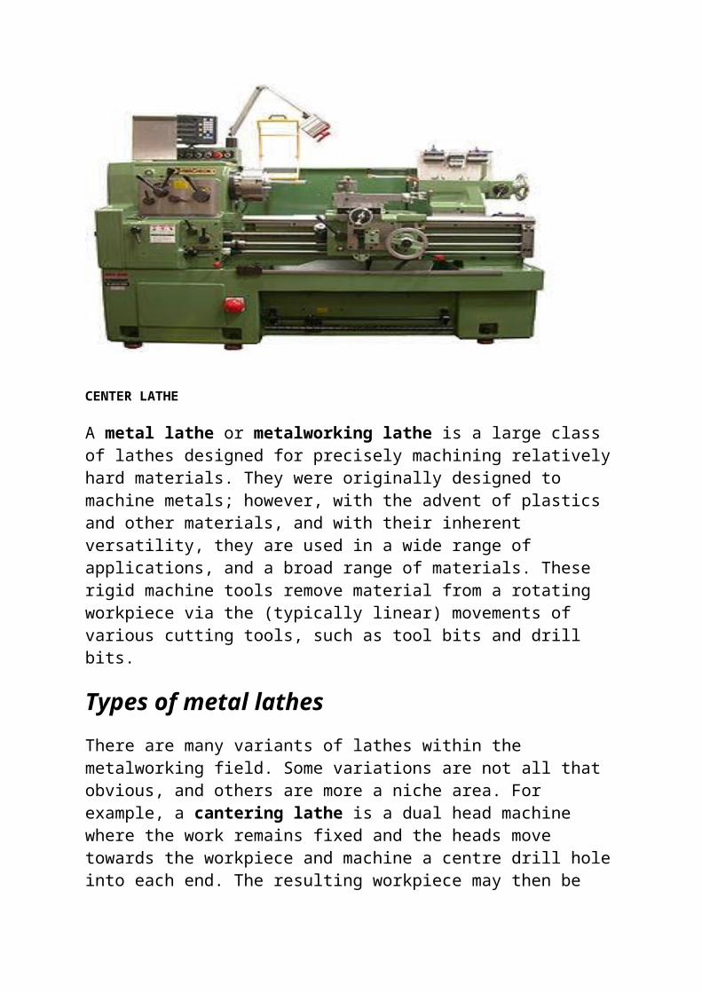
CENTER LATHE

A metal lathe or metalworking lathe is a large class of lathes designed for precisely machining relatively hard materials. They were originally designed to machine metals; however, with the advent of plastics and other materials, and with their inherent versatility, they are used in a wide range of applications, and a broad range of materials. These rigid machine tools remove material from a rotating workpiece via the (typically linear) movements of various cutting tools, such as tool bits and drill bits.
Types of metal lathes
There are many variants of lathes within the metalworking field. Some variations are not all that obvious, and others are more a niche area. For example, a cantering lathe is a dual head machine where the work remains fixed and the heads move towards the workpiece and machine a centre drill hole into each end. The resulting workpiece may then be used "between centers" in another operation. The usage of the term metal lathe may also be considered somewhat outdated these days, plastics and other composite materials are in wide use and with appropriate modifications, the same principles and techniques may be applied to their machining as that used for metal.
CENTER LATHE / ENGINE LATHE / BENCH LATHE
TWO-SPEED BACK GEARS IN A CONE-HEAD LATHE.

A TYPICAL CENTER LATHE.
The terms centre lathe, engine lathe, and bench lathe all refer to a basic type of lathe that may be considered the archetypical class of metalworking lathe most often used by the general machinist or machining hobbyist. The name bench lathe implies a version of this class small enough to be mounted on a workbench (but still full-featured, and larger than mini-lathes or micro-lathes). The construction of a centre lathe is detailed above, but depending on the year of manufacture, size, price range, or desired features, even these lathes can vary widely between models.
Engine lathe is the name applied to a traditional late-19th-century or 20th-century lathe with automatic feed to the cutting tool, as opposed to early lathes which were used with hand-held tools, or lathes with manual feed only. The usage of "engine" here is in the mechanical-device sense, not the prime-mover sense, as in the steam engines which were the standard industrial power source for many years. The works would have one large steam engine which would provide power to all the machines via a line shaft system of belts. Therefore early engine lathes were generally 'cone heads', in that the spindle usually had attached to it a multi-step pulley called a cone pulley designed to accept a flat belt. Different spindle speeds could be obtained by moving the flat belt to different steps on the cone pulley. Cone-head lathes usually had a countershaft (lay shaft) on the back side of the cone which could be engaged to provide a lower set of speeds than was obtainable by direct belt drive. These gears were called back gears. Larger lathes sometimes had two-speed back gears which could be shifted to provide a still lower set of speeds.
When electric motors started to become common in the early 20th century, many cone-head lathes were converted to electric power. At the same time the state of the art in gear and bearing practice was advancing to the point that

manufacturers began to make fully geared headstocks, using gearboxes analogous to automobile transmissions to obtain various spindle speeds and feed rates while transmitting the higher amounts of power needed to take full advantage of high speed steel tools.
The inexpensive availability of electronics has again changed the way speed control may be applied by allowing continuously variable motor speed from the maximum down to almost zero RPM. (This had been tried in the late 19th century but was not found satisfactory at the time. Subsequent improvements have made it viable again.)
TOOLROOM LATHE
A tool room lathe is a lathe optimized for tool room work. It is essentially just a top-of-the-line centre lathe, with all of the best optional features that may be omitted from less expensive models, such as a collets closer, taper attachment, and others. There has also been an implication over the years of selective assembly and extra fitting, with every care taken in the building of a tool room model to make it the smoothest-running, most-accurate version of the machine that can be built. However, within one brand, the quality difference between a regular model and its corresponding tool room model depends on the builder and in some cases has been partly marketing psychology. For name-brand machine tool builders who made only high-quality tools, there wasn't necessarily any lack of quality in the base-model product for the "luxury model" to improve upon. In other cases, especially when comparing different brands, the quality differential between (1) an entry-level centre lathe built to compete on price, and (2) a tool room lathe meant to compete only on quality and not on price, can be objectively demonstrated by measuring TIR, vibration, etc. In any case, because of their fully-ticked-off option list and (real or implied) higher quality, tool room lathes are more expensive than entry-level centre lathes.
TURRET LATHE AND CAPSTAN LATHE
Turret lathes and capstan lathes are members of a class of lathes that are used for repetitive production of duplicate parts (which by the nature of their cutting process are usually interchangeable). It evolved from earlier lathes with the addition of the turret, which is an indexable tool holder that allows multiple cutting operations to be performed, each with a different cutting tool, in easy, rapid succession, with no need for the operator to perform setup tasks in between (such as installing or uninstalling tools) nor to control the tool path. (The latter is due to the tool path’s being controlled by the machine, either in jig-like fashion [via the mechanical limits placed on it by the turret's slide and stops] or via IT-directed servomechanisms [on CNC lathes].)

There is a tremendous variety of turret lathe and capstan lathe designs, reflecting the variety of work that they do.
GANG-TOOL LATHE
A gang-tool lathe is one that has a row of tools set up on its cross-slide, which is long and flat and is similar to a milling machine table. The idea is essentially the same as with turret lathes: to set up multiple tools and then easily index between them for each part-cutting cycle. Instead of being rotary like a turret, the indexable tool group is linear.
MULTISPINDLE LATHE
Multispindle lathes have more than one spindle and automated control (whether via cams or CNC). They are production machines specializing in high-volume production. The smaller types are usually called screw machines, while the larger variants are usually called automatic chucking machines, automatic chuckers, or simply chuckers. Screw machines usually work from bar stock, while chuckers automatically chuck up individual blanks from a magazine. Typical minimum profitable production lot size on a screw machine is in the thousands of parts due to the large setup time. Once set up, a screw machine can rapidly and efficiently produce thousands of parts on a continuous basis with high accuracy, low cycle time, and very little human intervention. (The latter two points drive down the unit cost per interchangeable part much lower than could be achieved without these machines.)
Rotary transfer machines might also be included under the category of multispindle lathes, although they defy traditional classification. They are large, expensive, modular machine tools with many CNC axes that combine the capabilities of lathes, milling machines, and pallet changers.
CNC LATHE / CNC TURNING CENTER
CNC LATHE WITH MILLING CAPABILITIES

AN EXAMPLE TURNED VASE AND VIEW OF THE TOOL TURRET
CNC lathes are rapidly replacing the older production lathes (multispindle, etc.) due to their ease of setting and operation. They are designed to use modern carbide tooling and fully utilize modern processes. The part may be designed and the tool paths programmed by the CAD/CAM process, and the resulting file uploaded to the machine, and once set and trialled the machine will continue to turn out parts under the occasional supervision of an operator.
The machine is controlled electronically via a computer menu style interface; the program may be modified and displayed at the machine, along with a simulated view of the process. The setter/operator needs a high level of skill to perform the process, however the knowledge base is broader compared to the older production machines where intimate knowledge of each machine was considered essential. These machines are often set and operated by the same person, where the operator will supervise a small number of machines (cell).
The design of a CNC lathe has evolved yet again however the basic principles and parts are still recognizable, the turret holds the tools and indexes them as needed. The machines are often totally enclosed, due in large part to Occupational health and safety (OH&S) issues.
With the advent of cheap computers, free operating systems such as Linux, and open source CNC software, the entry price of CNC machines has plummeted. For example, Sherline makes a desktop CNC lathe that is affordable by hobbyists.

JIG GRINDERA jig grinder is a machine tool used for grinding complex shapes and holes where the highest degrees of accuracy and finish are required.
The jig grinder is very similar to a jig borer, in that the table positioning and spindles are very accurate (far more so than a manual milling machine or lathe). It is almost exclusively used by tool and dies makers in the creation of jigs or mating holes and pegs on dies. There are usually many peripheral elements to a large jig grinder, including separate hydraulic motors, air compressors, and various cooling systems for both the hydraulic circuit and supplying coolant to the work and machine itself.
The machine operates by a high speed air spindle rotating a grinding bit. The air spindles are removable and interchangeable to achieve varying surface speeds. Some spindles are fixed speed (60000 rpm), others are adjustable (30000-50000 rpm), and still others are very high speed (175000 rpm). The machines have a standard X-Y table with the notable exception of knee travel. All axes are indexed to .0001" via a vernier scale on the handwheels, with higher accuracy available with the use of measuring bars. The machine head has two vertical travels, one rough head adjustment and the other a precise spindle adjustment. The spindle to which the detachable air spindle mounts also rotates at a variable speed and can typically outfeed .100" while running, again with an accuracy of .0001" on the handwheel or greater, for very precise hole, peg and surface grinding. A well-kept jig grinder will reliably position work to a higher degree of accuracy than is possible with handwheels alone. These features are all critical in positioning a hole and peg system a precise distance from a reference surface or edge.
JIG GRINDING MACHINE
COLD SWAGING MACHINESwaging is a forging process in which the dimensions of an item are altered using a die or dies, into which the item is forced. Swaging is usually a cold working process; however, it is sometimes done as a hot working process.
Swaging machines form a workpiece by forcing it into a die to reduce or increase the diameter of tubes or rods. Swaging is done by placing the tube or rod inside a die or dies that hammer together to reduce the diameter of the metal. Swaging machines do not result in the loss of material, only material deformation. Since there is no material loss, swaging machines are commonly used with precious metals. Swaging and swaging machines are commonly considered cold forming processes, but may also be done as a hot forming process in some situations. Swaging machine processes are typically divided into two categories, tube swaging and rotary swaging.
Tube swaging machines use a process similar to drawing wire. These swaging machines can be expanded by placing a mandrel in the tube and applying radial, compressive forces on the outer diameter, which allows the inside shape to differ from the outer, circular diameter. Cold tube swaging machines are commonly used with aluminium, copper, and thin steel.
Rotary swaging, also known as radial swaging, is often a cold working process used to reduce tube diameter, produce a tapered end, or to add a point to a round

workpiece. This type of swaging machine uses two or four dies that hammer up to 2,000 a minute. Dies are mounted on the machine’s spindle, located inside a cage containing rollers, which is rotated by a motor. As the spindle spins inside the rotary swaging machine, the dies push out to ride the cage by centrifugal force. When the dies cross the rollers, they push the dies together due to their large size. Like tube swaging, rotary swaging can also create internal shapes inside the tube through use of a mandrel, as long as the shape has a constant cross-section. Rotary swaging machines are common in two basic types, standard and butt swaging. Butt swaging machines contain sets of wedges that close the dies onto the workpiece by placing them between the annular rollers and the dies, often by use of a foot pedal. These swaging machines allow the piece to be inserted without the dies closing on it. Common applications for swaging machines include attaching fittings to cables or pipes, pipe flaring, sawmilling, fire arms and ammunition, rubber components, automotive components, aerospace applications, agricultural machinery, measurement and adjustment systems, medical devices, optics, tool construction, welding and brazing devices, jewellery manufacture, metal joining and fixtures, and more.
HEAT TREATMENT PROCESSESThe amount of carbon present in plain carbon steel has a pronounced effect on the properties of steel and on the selection of suitable heat treatments to attain certain desired properties. Various heat treatment processes like carburising, tempering, induction hardening, stress reduction, shot blasting etc. are done in the various parts of gun in heat treatment section.
Annealing: Steel is annealed to reduce the hardness, improve machinability, facilitate cold-working, and produce a desired microstructure. Full annealing is the process of softening steel by a heating and cooling cycle, so that it may be bent or cut easily. In annealing, steel is heated above the transformation temperature to form austenite, and cooled very slowly, usually in the furnace.
There are several types of annealing like black annealing, blue annealing, box annealing, bright annealing, flame annealing, intermediate annealing, isothermal annealing, process annealing, recrystallisation annealing, soft annealing, finish annealing and spheroidizing. These are practiced according to their different final product properties in the industry.

Normalizing: In normalizing steel is also heated above austenitizing temperature, but cooling is accomplished by still air cooling in a furnace. Steel is normalized to refine grain size, make its structure more uniform, or to improve machinability. When steel is heated to a high temperature, the carbon can readily diffuse throughout, and the result is a reasonably uniform composition from one area to the next. The steel is then more homogeneous and will respond to the heat treatment in a more uniform way.
The process might be more accurately described as a homogenizing or grain-refining treatment. Within any piece of steel, the composition is usually not uniform throughout. That is, one area may have more carbon than the area adjacent to it. These compositional differences affect the way in which the steel will respond to heat treatment. Because of characteristics inherent in cast steel, the normalizing treatment is more frequently applied to ingots prior to working, and to steel castings and forgings prior to hardening.
Hardening: Hardening is carried out by quenching steel that is cooling it rapidly from a temperature above the transformation temperature. Steel is quenched in water or brine for the most rapid cooling, in oil for some alloy steels, and in air for certain higher alloy steels. With this fast cooling rate, the transformation from austenite to pearlite cannot occur and the new phase obtained by quenching is called martensite. Martensite is a supersaturated metastable phase and has body cantered tetragonal lattices (bct) instead of bcc. After steel is quenched, it is usually very hard and strong but brittle. Martensite

looks needle-like under microscope due to its fine lamellar structure.
Tempering: Tempering (formerly called drawing), consists of reheating a quenched steel to a suitable temperature below the transformation temperature for an appropriate time and cooling back to room temperature. Freshly quenched martensite is hard but not ductile. Tempering is needed to impart ductility to martensite usually at a small sacrifice in strength. The effect of tempering may be illustrated as follows. If the head of a hammer were quenched to a fully martensitic structure, it probably would crack after the first few blows. Tempering during manufacture of the hammer imparts shock resistance with only a slight decrease in hardness. Tempering is accomplished by heating a quenched part to some point below the transformation temperature, and holding it at this temperature for an hour or more, depending on its size. The microstructural changes accompanying tempering include loss of acicular martensite pattern and the precipitation of tiny carbide particles. This microstructural is referred to as tempered martensite.
Stress Relieving: When a metal is heated, expansion occurs which is more or less proportional to the temperature rise. Upon cooling a metal, the reverse reaction takes place. That is, a contraction is observed. When a steel bar or plate is heated at one point more than at another, as in welding or during forging, internal stresses are set up. During heating, expansion of the heated

area cannot take place unhindered, and it tends to deform. On cooling, contraction is prevented from taking place by the unyielding cold metal surrounding the heated area. The forces attempting to contract the metal are not relieved, and when the metal is cold again, the forces remain as internal stresses. Stresses also result from volume changes which accompany metal transformations and precipitation. The term stress has wide usage in the metallurgical field. It is def1Ůed simply as bad or force divided by the cross-sectional area of the part to which the bad or force is applied. Internal, or residual stresses, are bad because they may cause warping of steel parts when they are machined. To relieve these stresses, steel is heated to around 1100 0F (595 0C) assuring that the entire part is heated uniformly, then cooled slowly back to room temperature. This procedure is called stress relief annealing, or merely stress relieving.