FINAL REPORT PRODUCTION ENGINEERING CDC- - … · =1 PRODUCTION ENGINEERING PROGRAM TO DEVELOP...
88
FINAL REPORT =1 PRODUCTION ENGINEERING PROGRAM TO DEVELOP IMPROVED MASS-PRODUCTION PROCESS FOR M42/M46 GRENADE BODIES CD C- _, Prepared For: Commander 3W -- C U.S. Army Armament Research and C..* Development Command Large Caliber Weapons Systems Lab, Submunitions Section (DRDAR-LCU-DS) Mr. Joe Manna Dover, New Jersey 07801 Contract: DAAK10-77-C-0050 U AUG 30 198[~ March, 1978A D=UIM ON STATEME1T Aw Appwoved for pxihli, re!si'a; Distribution Unlimito, ORIGINAL CONTAINS COLOR PLATES: AL.L DDO . REPRODUCTIONS WILL BE IN BLACK AND WHITE 0 0Rog v n CORPORATION 07- 06 0ORLANDO, FLORIDA
Transcript of FINAL REPORT PRODUCTION ENGINEERING CDC- - … · =1 PRODUCTION ENGINEERING PROGRAM TO DEVELOP...
FINAL REPORT
=1 PRODUCTION ENGINEERING PROGRAM
TO DEVELOP IMPROVED MASS-PRODUCTION PROCESS
FOR
M42/M46 GRENADE BODIES
CDC-
_, Prepared For: Commander3W --C U.S. Army Armament Research and
C..* Development CommandLarge Caliber Weapons Systems Lab,Submunitions Section (DRDAR-LCU-DS)Mr. Joe MannaDover, New Jersey 07801
Contract: DAAK10-77-C-0050
U AUG 30 198[~
March, 1978A
D=UIM ON STATEME1T Aw
Appwoved for pxihli, re!si'a;Distribution Unlimito,
ORIGINAL CONTAINS COLOR PLATES: AL.L DDO .REPRODUCTIONS WILL BE IN BLACK AND WHITE
0 0Rogv n CORPORATION07- 06 0ORLANDO, FLORIDA

7
Q RODUCTION NGIN EEIN GPRGA
TO DEVELOP IMPROVED MASS -PRODUCTION PROCESS
FOR
_Y42/,.M46 RENADE BODIES,
Prepared For: CommanderU.S. Army Armament Research and
Development CommandLarge Caliber Weapons Systems Lab,Submunitions Section (DRDAR-LCU-DS)Mr. Joe MannaDover, New Jersey 07801
Contract: ~ l- 7 G ~
AUG 30 1978
~RIGINAL CONTA INS COLOR PLATES:,ALL U0UG3017REPRODUCTIO'NS WILL BE IN BLACK AND W"E.
DAYRON CORPORATION Distr .... d
ORLANDO, FLORIDA
i V A

TABLE OF CONTENTS
Page
FOREWORD.... .. .. .. .. .. . .. .. .. .. .. .. .. .. . 1
1. INTRODUCTION. .. ..... ..... .... ..... ... 5
2. D~ISCUJSSION .. .. ..... ..... .. ... ..... ..... 6
2.1 Cylinder Development .. .. .. .... .... .... 6
2. 1.1 Welded Tubing ... ..... .... .... 7
2.1.2 Seamless Mechanical Tubing. .. .. ...... 10
2.1.2. 1 Seamless Mechanical Tubing WithKnurled Fragment Pattern. .. ...... 12
2.1.3 Punch Press-Formed Cylinder, Laser/Electron Beam Welded joint . .. .. .. . .17
2.2 Dome Development .. .. .... ..... .... ... 18
2.2.1 Transfer Press/Transfer Die .. ... ....... 19
2.3 joining the Cylinder and Dome . . .. .. .. .. . .21
2.3.1 Inertia-Welded Assembly .. . . . .. .. . .22
2.3. 1.1 Component Design for the Inertia-
Welded Process .. .. ... ...... 24
2.3.1.2 Test Results. .. ...... . . . . 26
2.3.1.3 Conclusions .. .. .. .. .. .. 26
2.3.2 Brazed Assembly .. .. ..... ...... . 34
2.3.2.1 Component Design for the BrazingProcess. .. ... ..... ....... 38
Ij
I_____ _ _;

TABLE OF CONTENTS (Continued)
Pagse
2.3.2.2 Braze Material ..... ........... 40
== 2.3.2.3 Braze/Heat-Treat Process ....... 41
2.3.2.3.1 Continuous Braze/Heat-Treat (Inert Gas).. 42
2.3.2.3.2 Batch Braze/Heat-Treat(Vacuum) ......... .. 45
2.3.2.4 Longitudinal, Transverse Load andPush-Out Tests...........48
2.4 Quality Assurance ....... .................. 54
2.4.1 Brazing and Heat-Treatment of the BodyAssembly ....... .................. 54
2.4.2 Integrity of the Brazed joint ......... . 56
f 4.3 longitudinal and Transverse Strength of
the Body Assembly as Tested in AccordanceWith MILG48047 .............. . 56
2.4.4 Tensile Force to Remove Studs from Dome . . 57
2.4.5 Dimensional Control of Component Parts . . 58
3. PROPOSED M42/M46 GRENADE BODY FABRICATION PROCESS 64
3.1i ProceFo w hart.........................643.1 Process Flow Chart ... .................. ... 64
1 3.3 Body Assembly Cost Estimates .......... . . . 65
3.4 Estimated Scrap Rate ...... ................. 65
= [I _"
TABLE OF CONTENTS (Continued)
Page
4. CONCLUSIONS . . . . . . . . . . . . . .. .. ..... . . . 70
~~ = 5. RECOMMENDATIONS..... .. . . . . . . . *** 71
APPENDIX I -PROCESS PLANS. .. .. .. .. . . . .. . . . . 73
=APPENDIX II -M42/M46 GRENADE BODY FACILITY COSTS . . . . . 79
LIST OF PHOTOGRAPHS
Page
Photograph 1 M42 Grenade Body Brazed Assembly .... ......... 4
Photograph 2 Knuring Tool .g.. ................ .. J16
Photograph 3 Knurling Tool Installed in Machine . . ....... 16
Photograph 4 Shrapnel Pattern Being Knurled Into M42 GrenadeCylinder .... ....................... 16
Photograph 5 Modified Thread-Rolling Machine to EmbossShrapnel Pattern Into M42 Grenade Body Cylinder . . 16
Photograph 6 Inertia-Welded Body Assembly (Before FinalMachining Operations) ................... .... 29
* Photograph 7 Cylinder Being Held in Nonrotating Fixture . . . .. 30
Photograph 8 Dome Being Held in Rotating Head .... .......... 30
Photograph 9 Dome and Cylinder Coming Together to BeginWelding Cycle ................ . . .. 30
Photograph 10 M42 Grenade Assembly Being Inertia Welded . . . . 30
Photograph 11 M42 Brazed Grenade Body Assembly and Components 33
iv
ErI
LIST OF FIGURES AND DRAWINGS
Page
Figure 1 Dome, Grenade M46 (For Inertia-Welding Process) . 31
Figure 2 Rockwell Hardness Readings After Welding(Inertia-Welded Grenade Body Assembly) ........ 32
Figure 3 Longitudinal/Transverse Strength vs. TemperingTemperatures (M42 Brazed Assembly Grenade Body). 52
Figure 4 Process Flow Chart - M42/M46 Grenade Body(Brazed Assembly) ....... . . . . . . . . . . 67
Figure 5 M42/M46 Grenade Body Pricing Information. . . . . 68
Figure 6 M42/M46 Grenade Body Material Costs ...... 69
Drawing Number
9327237 Tubing, Embossed ..................... 60
9327238 Dome, Embossed .................. 61
9327239 Cylinder . . . . . . ............... 62
9327240 Body, Assembly ....... ................... 63
vNA
- -- -Iz , -

FOREWORD
\JThis report describes the work performed by Dayron Corporation under
Contract DAAKlO-77-C-0050 for the development of a new process for manu-
facturing M42/M46 grenade bodies at reduced cost without jeopardizing munition
effectiveness, safety or reliability.
The present M42/M46 grenade body fabrication technique; a blank,
cup and draw process, was at the threshold of the state-of-the-art when it
was selected some years ago. It has been developed and refined over the
years such that it is capable today of producing a most demanding product in
very high volume to exacting quality requirements. Without question, it is a
successful process. Its main drawback is that it is a relatively expensive
process and will likely remain so. A secondary disadvantage is the inherent
tendency of this blank, cup and draw technique to produce "smiles" or cracks
which necessitate costly trimming and significant inspection to maintain
requisite quality standards.
I Since the selection of the blank, cup and draw process was made,
Ithere have been most significant advances in the state-of-the-art of alloy
steel tube fabrication techniques. Today it is routine to manufacture accurately
1' welded tubing using molybdenum steel alloys which was not possible a few
years ago. Dayron opted to take advantage of these modern techniques to
!!I
I= -- _ --
fabricate the tube portion of the grenade body. The dome would be separately
produced and Ehe two elements would be joined to form the complete unit.
Various designs and processes were investigated for the fabrication of
a two-piece grenade body assembly consisting of a dome attached to a cylinder.
Numerous techniques were initially reviewed and culled. Such candidate pro-
cesses as laser-beam welding, electron-beam welding and mechanical crimping
were evaluated and eliminated from consideration in favor of more promising
techniques which are discussed herein. The following processes were investi-
gated in depth:
CYLINDER FABRICATION
* Cylinders made from welded tubing (embossed material)
I * Cylinders made from seamless mechanical tubing
0 Embossed fragment pattern knurled by special machine into inside of
seamless mechanical tubing
* Punch press-formed cylinders with laser/electron beam-welded joint
DOME FABRICATION
0 Domes made by transfer press/transfer die (embossed material)
TOINING CYLINDER AND DOME
0 Dome/cylinder attachment by inertia welding
* Dome/cylinder attachment by furnace brazing
2IN

RESULTS
The optimum design and process were found to be a two-piece assembly
consisting of a cylinder fabricated from embossed 4140 steel in a tube mill and
attached by furnace brazing to an embossed dome fabricated in a transfer press.
This grenade body assembly easily passed all M42 grenade requirements.
Tests indicate that with optimum process development, it will also pass the
M46 grenade requirements. This achievement will eliminate the need for M46
grenades. Photograph Number I on the following page illustrates the final
two-piece configuration. Note the undistorted fragmentation pattern obtained
with the tube-mill weldment.
The projected high-volume production cost for the new two-piece
grenade is about one-third less than the realistically projected cost of the
current configuration. .se we believe the two-piece configuration to be
a superior product capable of being produced at a substantially lower cost, we
recommend that a follow-on engineering development program be promptly
initiated to produce and test 50,000 two-picce grenade bodies.
When it is evident during the follow-on program that the new process
is successful and superior to the present process, we also recommend that an
initial production capability be commenced to fully prove out the process and
to determine the economic practicality of converting the current six producers
to the new process.
ii3

(Phiotograph 1 42 GRENADE B3O-Y BRAiZED ASSEMIBLX 4

1. INTRODUCTION
The M483A1 155MM projectile and M509 eight-inch round are
submissiled munitions. The M483A1 is used with the self-propelled
M109A Howitzer. The M483A1 contains M42 and M46 grenades while
the M509 round contains M42 grenades only. The M42 and M46
grenades are submunitions approximately 1.5 inches in diameter and
3 inches in length, each consisting of a body assembly, an M223
fuze and a tape stiffener assembly.
The body assembly for each of the two submunitions is different
in that the M46 grenade is smooth-walled and the M42 grenade has an
embossed inner surface. The grenades must be strong enough to with-
stand extraordinary longitudinal and transverse forces experienced
during projectile launch. The manufacturing method for the body now
used and proposed for use in plants as they come on-stream has its
foundation in deep drawing a cup from cold rolled strip stock (embossed
for the M42 body) with intermediate annealing operations followed by
ancillary machining, heat-treating, protective finishing and inspection
steps. This process, particularly the deep draw, generates large
amounts of scrap. Further, the drawing operation inherently produces
"smiles" or cracks in the grenade body walls necessitating very close
inspection, including ultrasonic final inspection to assure a quality
5

product. The cost of using the existing process is so great that
exploration of more efficient processes is mandated for the projected
extremely high production quantities of these grenades. The improved
process recommended herein not only produces a superior product, but i 5
results in significant projected cost savings as compared with the
current blank, cup and draw technique.
Dayron has been successful in developing a two-piece assembly
which ,vill more than satisfy the desired technical requirements. This
assembly consists of a cylinder and a dome copper-brazed together.
The following discussion will describe and relate all the work and
investigations performed in obtaining this optimum grenade body design.
2. DISCUSSION
2.1 Cylinder Development
Various methods of obtaining a cylinder of the desired physical
and dimensional requirements were initially considered. It was
decided that the following three processes would receive in-depth
study and inve.stigation:
I. Emboss coiled 4140 steel flat stock in a Fenn mill to
give the desired standard M42 grenade fragment pattern and then
form the coiled stock into a tube and weld it in one continuous
operation. The resulting tube would then be cut into the proper
cylinder lengths.
6

IIII. Purchase commercially made seamless mechanical 4140
steel tubing and cut it into the appropriate cylinder lengths for
M46 grenades. For M42 grenades, the cylinders would have a
fragmentation pattern knurled into the inside diameter by a
sp -,ial machine.
III. Emboss coiled 4140 steel stock in a Fenn mill to give
the desired standard M42 fragmentation pattern and then feed
the coiled stock into a progressive punch press die that would
stamp and form the coil into a cylinder. The seam would later
be welded by laser or electron beam. M46 cylinders would be
fabricated from nonembossed material.
The above three techniques for cylinder fabrication are next
discussed in detail:
2.1.1 Welded Tubinq
Approximately twenty (20) of the most respected tube
welding companies in the United States were contacted and
tubing requirements discussed with them. It was decided
that three (3) had the expertise to be successful in fabricating
a tube in 4140 steel to the required dimensional and physical
specifications. These companies were:
1==
7
ri0 Babcock & Wilcox, Alliance, Ohio
* True Temper, Geneva, Ohio
* Metalmatic, Minneapolis, Minnesota
Babcock & Wilcox was awarded a contract by Dayron
because of their in-depth experience in successfully producing
various alloy steel tubing. The contract was to fabricate and
deliver 650 feet of embossed, 4140 alloy steel, welded tubing
to our specifications.
The 4140 material was obtained from the Sharon Steel
Company, Sharon, Pennsylvania, and sent to Amron Corporation,
Waukesha, Wisconsin, for embossing. The material was
annealed after embossing and was then shipped to Ohio Steel
Slitters, Canton, Ohio, to have the 7.825" wide by .119"
thick material slit to 4.830"+ .020" width. The slit material
was then shipped to Babcock & Wilcox for tube fabrication.
The remaining material at Ohio Steel Slitters was shipped to
Kratz-Wilde Company to be fabricated into domes.
Babcock & Wilcox produced the tubing using the follow-
ing continuous operations:
ii88

Place coiled material on tube fabrication line.
* Slit material to final width.
* Form into tubing (Abney-Etna Tube Mill).
* Weld seam (Therma-Tool High Frequency Welder).
* Ultrasonic inspection.
* Trim weld (outside and inside).
* Cut to length (24 feet).
0 Conveyor transfer to full anneal furnace at 13000F.
* Straighten tubing.
* Eddy-current inspection for cracks, voids, weld and
overall material integrity per ASTM 513-76.
* Oil, pack and ship.
The tubing was inspected at Dayron for dimensional
characteristics. The outside diameter varied from 1.513" to
1.511", well within the Government print requirements of
1.524" - 1.509". The wall thickness measured .120" which
was less than anticipated. The coil material measured .119"
before tube-forming. The wall thickness will increase as the
material is formed from a flat to a round configuration during
the fabrication of smooth-walled tubing. Because of the emboss-
j Ing in the inside, the wall thickness did not increase as much
9

as expected; therefore, the inside diameter measured 1.274"
instead of the desired 1.254". This undersize wall thickness
condition will reduce the transverse strength of the finished
grenade body, but should not affect longitudinal strength as
failure in this mode occurs in the machined area near the open end.
The hardness of the tubing as received measured Rockwell
"A" Scale 64 which is a little harder than optimum for machina-
bility. Babcock & Wilcox stated that the hardness can be
reduced during the fabrication operation should we so desire.
As evidenced by tests and inspections made by Dayron,
the tubing material as supplied is very consistent in physical
and dimensional characteristics and can be used directly as
received for M42 grenade body production.
2.1.2 Seamless Mechanical Tubing
Several companies that specialize in manufacturing
seamless mechanical tubing in alloy steels were contacted.
After careful consideration, Quanex Corporation (Michigan
Seamless Tube Company) of South Lyon, Michigan, was given
a purchase order to fabricate 250 feet of soft annealed 4140
steel seamless tubing to the following dimensions:
10 7M
SE

r D (inc ) .5..
Outside Diameter (inches) 1.517 + .007 - .002
inside Diameter (inches) 1. 258 + .002 - .007
Wall Thickness (inches) .130 + .010 - .010
The diameters of the received material were very
consistent, measuring between 1.521" and 1.523" on the out-
side and 1.256" to 1.258" on the inside. This close control
was very impressive. The wall thickness, however, varied
from .122" to .140" for a total .018" variation. Because of
this variation, the material could not be successfully used for
fabricating M46 cylinders because after machining the inside
diameter to meet concentricity requirements, the resultant inside
diameter measured approximately 1.275" (.015" oversize). The
maximum inside diameter on the Government drawing is 1.260".
Ordering new material to different dimensions was con-
sidered. However, the embossed welded tubing from the tube
mill was at that time already evidently successful. It was
therefore decided not to perform additional work on seamless
mechanical tubing, but to fully concentrate our investigation on
the welded tubing.
11 _

The unit cost of each grenade body candidate, welded
versus seamless, is nearly identical. However, the inside
diameter of the welded tubing does not require a machining
operation to meet print requirements. This factor means that
more scrap and labor is expended in fabricating grenade bodies
from seamless tubing which further supported our conclusion
to devote all of our attention to the welded-cylinder approach.
The hardness of the received seamless tubing was
Rockwell "A" 52 and machined in an acceptable manner.
Transverse and longitudinal tests of heat-treated sample
seamless grenade cylinders showed very good strength.
Seamless mechanical tubing could be successfully used in
fabricating a two-piece M46 grenade body assembly should
the preferred welded tubing approach later prove to be
unsatisfactory.
2.1.2.1 Seamless Mechanical Tubing With Internal
Knurled Fragment Pattern
In order to produce an M42 grenade body from
seamless mechanical tubing, it is necessary to cut or
form a shrapnel pattern into the inside diameter of the
12

cylinder. High-speed knurling and thread-forming on
exterior surfaces are very well-developed and success-
ful techniques. Because of these economical and
accepted practices, Dayron proposed to perform tests
to determine the feasibility of knurling the required
shrapnel pattern on the inside of a cylinder.
Several leading companies that design and build
thread-rolling equipment were contacted. A contract
was awarded to Tesker Manufacturing Corporation,
Saukville, Wisconsin, to develop a process to knurl
the desired internal pattern. Tesker Manufacturing
was unable to fabricate a successful knurling tool.
Dayron then contacted Roehlen Engraving Company,
Rochester, New York, the current supplier of M42
grenade body Fenn mill embossing rolls. Roehlen was
awarded a cuxiu**L am'i labricated a knurling tool for
use in the modified Tesker thread-rolling machine.
This tool reproduces exactly the currently accepted
M42 grenade body pattern. (See Photograph Number 2.)
I
- J=-=-7

Cylinders of 4140 steel were cut from bar stock
for use in the process development. The tooling was
installed (see Photograph Number 3) and process tests
performed. Very light knurling pressure v- s used on the
first samples. The pressure was gradually increased
until a pattern depth of .007" was achieved. It became
apparent at that time that a full depth of .015" to .020"
could not be obtained without sacrificing other dimen-
sional requirements. Using 9,000 pounds of roller
pressure to force the knurling tool .007" into the
annealed 4140 steel caused the outside diameter of the
cylinder to increase in size by .036" to .042" and also
caused an out-of-round condition of .015" T.I.R.
It was also noted that several revolutions of the
machine were needed to obtain the .007" depth ond that
each time the cylinder revolved, the teeth in the knu.linq
tool would not accurately line up with the pattern formed
on the previous revolution. As the pressure was
increased to obtain more pattern depth, the cylinder
inside diameter also increased, causing further mis-
alignment. The end result was unsatisfactory.
1

It is conceivable that by developing a highly
refined cylinder blank to compensate for the process
environments, an internal knurling process might be
successful. Howe.ver, with the concurrently successful
embossed welded tubing technique, it was decided to
suspend further work on the knurling approach. The
tooling and equipment used to conduct the above tests
are shown on the following page.
is
I
-5 14

-nm --
0z<
1-4
0 I-
Cl)
o co
E-4
1- 4 -q
ro
e6

2.1.3 Punch Press-Formed Cylinder, Laser/Electron Beam
Welded Joint
This third concept for cylinder manufacture consisted of
feeding embossed (M42) or nonembossed (M46) material into a
punch press progressive die and producing a cylinder in a
series of blanking, trimming and forming operations. The
cylinder would then be fed into an automatic laser or electron
beam welding machine to weld the cylinder seam closed.
Fifteen (15) companies with extensive experience in
punch press tooling design were contacted. The following three
companies were visited:
* Harig Manufacturing Company, Chicago, Illinois
* Weatherby Tool Company, Jacksonville, Florida
* Wright Manufacturing Company, Nashville, Tennessee
After much study and consultation with these people, it
was concluded that fabricating a cylinder with a seam capable
of being laser or electron beam welded would require exceAd-
ingly complex and expensive tooling which would be Impracti-
cable to maintain with production at rates of 1,400,000 units 4per month.
17
- - z- - _ - . . -= - _ __ __. . . .-= _ _ .. _-_ .. _
The reason for such difficulty is that the optimum joint
configuration for welding is a surface-to-surface contact. A
maximum of only a .005" space between surfaces can be tol-
erated in order to assure a reliable welded joint. The requisite
degree of alignment and joint preparation to achieve such
parallelism is considered beyon;d the state-of-the-art to
achieve in a punch press-developed cylinder.
The three tool companies all indicated that the total
forming and welding operation optimumly should be performed
automatically in a tube mill. Based upon the information
received and the unsatisfactory sample parts obtained during
our investigation, Dayron concluded that the punch press
process for cylinder fabrication was not economically feasible.
2.2 Dome Development
As stated earlier, Dayron's approach to fabricating an economi-
cal and reliable M42/M46 grenade body consists of attaching a dome
to a cylinder. Fabrication of the dome will be accomplished in a
transfer press using embossed (M42) or nonembossed (M46) coil stock.
Details concerning this process follow:
18R N

2.2.1 Transfer Press/Transfer Die
The Waterbury Farrel Division of Textron, Inc.,
Cheshire, Connecticut, was contacted early in the program
because of their expertise in developing tooling for the blank,
cup and draw method now being used to manufacture M42/M46
grenade bodies. Because of Waterbury's commitments to other
programs, they were unable to accept a timely dome develop-
ment contract from Dayron. After an extensive industry search,
a contract was awarded to Kratz-Wilde Machine Company,
Covington, Kentucky, to develop a transfer-press process to
produce a dome that could be used on both M42 and M46
grenade bodies.
Two dome designs were submitted to Kratz-Wilde; one
to be used for a brazed assembly (Drawing Number 9327238)
and one to be used in conjunction with an inertia-welded
assembly. (See Figure Number 1.)
In order t. provide a dome that contained the desired
fragmentation pat ern used in the M42 grenade, it was necessary
to begin the operation with embossed coil stock and then form
T
Jt

that material into a dome. Embossed 4140 steel coil stock
containing the current M42 shrapnel pattern ,vas o btained from
Amron Corporation, Waukesha, Wisconsin.
Kratz-Wilde was successful in developing the tooling
and fabricating domes to Drawing Number 9327238 (Brazed
Assembly Design). Their process required four (4) separate
dies representative of either a transfer press operation or
transfer die operation. Approximately 1,000 domes were pro-
duced to this configuration. The two .125" diameter holes
and one .209" diameter center hole were not included in these
initial dies, but would be incorporated in the final high-production
tooling necessary to meet the 1,400,000 unit-per-month antici-
pated production rate.
Material width to be used in the high-production tooling
would be 5.192", die progression 2. 160" and material thickness
.119". This press operation will yield three (3) dome blanks/
progression. The formed parts as received required a machining
operation to form the .045" + .020" radius at the inside open
end and a facing operation to meet the .005" perpendicularity
3 requirement.
2
L2

In high production, the .045" radius would be incor-
porated in the forming tooling and the .005" perpendicularity
requirement would be accomplished with a Blanchard automatic
grinding machine.
IKratz-Wilde was not successful in developing tooling
to produce domes to the inertia-welded assembly design. (See
Figure Number 1.) The embossed material fractured and pfJ.ed
up from the pattern grooves when any attempt was made to form
the material with the embossing on an outside radius. However,
solid material could be successfully formed for M46 grenade
domes. Based upon this peeling problem which would have been
costly and time-consuming to solve, it was decided to forego
further work in developing a press part for the inertia-welded
design. Parts used for inertia-welded assemblies were later
machined from bar stock in the evaluation of the inertia-welding
technique which is discussed in the following pages.
2.3 Toining the Cylinder and Dome
Of the many assembly processes initially evaluated, Dayron
j elected to concentrate on the development of two techniques which
- Iappeared most promising to attach the dome to the cylinder. The two
assembly methods were brazing and inertia welding. First we shall
- I discuss inertia welding.
21Mi----%.~-=~-
2.3.1 Inertia-Welded Assembly
Inertia welding is a unique form of friction welding
which utilizes kinetic energy stored in a flywheel system for
all of the needed heating and much of the required forging.
One workpiece Is fixed in a stationary holding device.
(See Photograph Number 7.) The other, clamped in a spindle
chuck (see Photograph Number 8 ) usually with attached fly-
wheel, is spun up rapidly. At a predetermined RPM, driving
power is cut and the fixed part is thrust against the rotating
part. Friction between the parts decelerates the flywheel,
converting stored energy to frictional heat -- enough to soften,
but not melt the contazting surfaces of the parts. The energy
level is established to be sufficient to achieve forging tempera-
tures. The rate of energy consumption is determined by the
w.ield itself. When the energy is fully consumed, the weld is
completed and flywheel rotation stops.
Inertia welding has many advantages over other metal-
joining processes. Some of these advantages are as follows:
* After initial setup, it is a machine-controlled process
with no subjective human skills involved.
222
- ==-~N V

* No external heat is applied. Only the frictional heat
generated by the two pieces and thrust pressure is used.
* There are no special conditions required -- no separate
location, no oxygen or gas, no glare shielding or
splatter protection, no ventilation. The process is
compatible with other machines in a production line.
• There is no flux or filler metal required for the process.
* Normally there is no special preparation required of
the contacting part surfaces. They can be inertia
welded directly from previous processing, whether
cast, forged, saw-cut or sheared.
* The bond itself is a forging, characterized by a fine
grain structure. It is free of impurities and voids and
the heat-affected zone is relatively narrow. This
results from the simultaneous application of energy and
thrust. The resultant torque extrudes the material off
its interfaces, throwing out surface inclusions and
oxides while working the metals at a p~Astic state
below melting temperature. Flash (the upset or
23

extruded metal from the weld interface) may be left
intact if permitted by design req "ements or it may be
removed by machining or shearing.
0 The process can be automated for continuous high
production (up to 1,000/hour per machine for M42/M46
grenades).
2.3.1.1 Component Design for the Inertia-Welded
Process
Material upset and subsequent flash are
inherent in the inertia welding process. Flash always
occurs at both outside diameter and inside diameter
surfaces of the weld interface and must always be
considered in the design of parts to be inertia-welded
The basic joint must be a butt weld since the process
involves thrusting one part axially against the other.
Early in the program, Dayron contacted and
visited Manufacturing Technology, Inc., Mishawaka,
Indiana, and worked closely with their engineers to
design the optimum M42/M46 grenade body assembly
joint for inertia welding. (See Photograph Number 6
24p

and Figure Number 1.)
Kratz-Wilde Machine Company, Covington,
Kentucky, was awarded a purchase order to develop a
dome for the inertia-welding process. Their approach
was to employ the blank, cup and draw method to form
the dome. The material used was .119" thick embossed
4140 steel as employed in current M42 grenade body
fabriration. The requisite dome configuration must
have a relatively broad flange to accept the axial
loading required by the inertia-welding process. After
considerable work, it was decided that the dome could
not be readily produced to the required design with the
selected technique because of the consistent severe
cracking and peeling up of the fragmentation pattern
during the reverse forming operation of the flange.
Domes were therefore machined from solid 4140 steel
bar stock in order to perform the inertia-welding tests.
An inertia welding machine was tooled at
Manufacturing Technology, Inc. and assemblies con-
sisting of embossed tubing and unembossed machined
25
domes were routinely welded with no difficulty. Tooling
and the inertia welding machine setup are shown in
Photographs Number 7, 8, 9 and 10.
2.3.1.2 Test Results
Inertia-welded M42 grenade body assemblies
were machined to final dimensions, heat-treated, tem-
pered at 725°F and subjected to longitudinal and trans-
verse load tests in accordance with Specification
MIL-G-48047. The results were very satisfactory with
an average longitudinal strength of 92,000 pounds and
an average transverse strength of 9,640 pounds.
2.3.1.3 Conclusions
The inertia welding of a dome to a cylinder
produces an acceptable M42/M46 grenade body assembly.
The welded joint is superior in strength to any other
design tested. There are, however, several short-
comings to this method of fabrication when compared
to the furnace-brazed assembly discussed in Section
2.3.2 of this report.
The disadvantages are as follows:
26

* The dome cannot be fabricated to the required
flanged design using embossed material and the
standard blank, cup and draw method.
* During the welding operation an exceedingly
hard zone is created in the joint area (see
Figure Number 2) which must be annealed
before final machining operations can be
economically performed.
-* Considerable flash is produced both in the
inside and outside of the assembly during the
welding operation. Secondary machinino
operations must be employed to remove the
flash.
* Overall length of the assembly cannot be held
to final dimensions during welding and, therefore,adteahndto fiaegha thereig.ethe assembly (cylinder length) must be oversize
i and then machined to final length after welding.
* The inertia welding process and equipment is
considerably slower and much more costly than
27
a furnace brazing system. One automatic
welding machine capable of producing 1 ,000
grenade assemblies per hour would cost $340,800.
Because of the above disadvantages, and because
of the advantages of brazing discussed next, Dayron has
selected brazing as the optimum means of attaching the
dome to the cylinder.
H
M-I
28

1'(Photograph 6) INERTIA-WELDED BODY ASSEMBLY(BEFORE FINAL MACH-INING OPERATIOM\11- 29
T1

1ca
f-4 '-.
co -
LX--
EL.
___ [-4
00
30 -
S"-.600 REF -A-
I AfO.- 20 .010 TYPALL AROUND
.020-.010 R-
.080-020 R
1.767-0100- !.294-.0050El
I@JB!.OI0 FIMi
I: 50+1 A
5 1
S- -. 0271I I/j~l~05-
4.00 ".490-:010
I MAT'L:-AISI 4140, SPEC ASTM A507I DOME, GRENADE M46
(For Inertia Welding Process)Figure 1 31
_ _ _ _ _ _ _ _ _ _ _ _ _ _ _ _ _ _ _A4

INERTIA WELDED GRENADE BODY ASSEMBLY
(Rockwell "A" Hardness Readings After Welding)
A49 A48
A4 9
Dome Portion -54
Niachlnef trom A554140 Steel Solid A55Bar Stock P.55
A7.8.A65
"eA65
A65
A65
Cylinder PortionFabricated from A65
Welded Tubing,4140 Steel A65Embossed Coil Stock
A6 5
A65
A65
A65
A65
-V A65
V
Figure 2 32
-U,=. .-

I. ' ==- k~ ~ - =_______-AL
(Photograph 11) M42 BRAZED GRENADE BODYASSEMBLY AND COMPONENTS
334

2.3.2 Brazed Assembly
IBrazing is a very reliable and economical method of
attaching two steel pieces together if the pieces can be
designed to provide a proper joining surface. The attachment
of two cylinders of different diameters is an ideal configuration
for brazing. The M42/M46 dome/cylinder design approaches the
optimum for the brazing technique.
Brazing provides the following advantages:
* Produces a leaktight joint. In brazing, capillary action
draws the molten filler metal into every crevice of the
closely fitted joint area, filling it completely. There
are no voids or gaps.
E Produces a ductile joint. Brazing joins metals at rela--itively low heats (when compared to welding), causing
little or no brittleness or stress in the joint area. The
-ductility of the joint is further increased by the broad
I I width of the typical lap joint to be used in the M42/M46
1grenade body. The combination of these two factors
imparts resistance to joint cracking or failure under
I severe conditions of shock,.vibration or sudden tempera-
ture change.
34
La
* Produces corrosion-resistant joint. Even a highly
corrosive atmosphere cannot corrode what it cannot
reach. A brazed joint is hard to reach since practically
all the filler metal is contained inside the joint, with
only a very fine line or fillet exposed at the surface.
* Produces joints requiring no finishing. The small sur-
face fillet or thin edge of a brazed joint requires no
special cleanup. A welded joint, however, requires
certain finishing operations which can include removal
of excess weld metal, annealing, machining to size and
stress-relieving to restore the metallurgical properties and
final dimensions of the welded assembly. On a pro-
duction basis, these cost differences become significant.
S.High-production adaptability. A brazing process can
be economically established to produce millions of
assemblies per month on a fully or partially automated 2basis. When compared to other assembly methods, a
proven brazing process requires minimal controls and
monitoring to consistently produce reliable assemblies.
35
The following types of brazing techniques were investi--
gated for use in fabricating the two-piece M42/M46 grenade
body assembly:
0 Multiple burners. This is the first step up from the
manual torch. A series of open-flame burners are
screwed into a pipe which is attached to a gas-air
compressor. A conveyor or turntable carries the assem-
blies past these burners. The size and positioning of
the burners are coordinated with conveyor speed to
bring just enough heat to the parts. This is a simple,
inexpensive and effective way to automate heating of
small assemblies.
9 Electric induction. This is a selective heating method
in which the joint assembly is placed in a high-fre-
quency electric field. Heating is fast and confined to
a limited area on the part. The heating cycle can be
automatically timed to produce joints of consistent
quality.
* Furnace heating. This is a high-production heating
method for similar-mass, small or medium-size
L-
- 36

assemblies such as the M42/M46 grenade bodies. The
parts to be brazed are initially assembled, brazing
alloy preplaced at the joint and the assemblies then
fed into a furnace which heats them to a predetermined
temperature. The parts emerge fully brazed.
There are several types of brazing furnaces --
batch or continuous, electrically heated or gas-fired.
Furnaces may use controlling atmospheres to prevent
oxidation, in which case fluxing may not be necessary.
For production of extremely critical brazed assemblies,
vacuum-furnace brazing is frequently used. This
method produces brazed joints of exceptional purity by
eliminating the presence of all gases. After considerable
study and consultation with the following brazing and
furnace equipment manufacturing companies, Dayron
elected to evaluate both the controlled atmosphere and
vacuum furnaces for use on the M42/M46 grenade program.
* Handy & Harman, New York, New York
* Lucas-Milhaupt, Inc., Cudahy, Wisconsin
- Sunbeam Corporation, Meadville, Pennsylvania
37
Z l] i i m

0 Ipsenlab, Rockford, Illinois
0 Lindberg (Sola Basic Inuustries) Chicag. , Illinois
A discussion of these two selected processes
appears in Section 2.3.2.3 of this report.
2.3.2.1 Component Design for the Brazing Process
In brazing, the molten filler metal is drawn
by capillary action between contiguous, closely fitted,
substantially symmetrical surfaces. The distance the
filler metal will flow in a joint depends bc h u-nn the
clearance between the mating surfaces and upon the
filler metal used. Molten copper will flow freely and
for greater distances than other filler metals in joints
with size-to-size fit (zero clearance) or an interference
fit (negative clearances). The distance of copper flow
increases as joint interference increases, up to the
point where the seizing and galling of mating surfaces
interferes with capillarity. Conversely, as joint clear-
ance, or gap, is increased, a clearance is reached at
which filler metal flow stops completely. Uniform fit
throughout the joint is important because nonuniform
fit will result in nonuniform strength.
38

For most applications, the recommended fit for
copper brazing of low-carbon steel is 0.000" to 0.003"
interference. High-carbon steels require a slightly
looser diametral fit, usually 0.001" clearance to 0.002"
interference. It Is, however, important to note that
joints with as much as 0.003" diametral clearance will
exhibit a strength exceeding the averace shear strength
of copper.
In general, lap joints are preferred for brazing.
The strength of these joints results from braze material
penetration between close, conforming surfaces, rather
than on external fillets. For optimum strength, the length
of the joint should be between two to three times the
thickness of the thinnest section.
Considering the above information, which was
obtained from the American Society for Metals on furnace
brazing of steel and from consultation with several other
authorities on the subject, Dayron elected to employ
the following joint for the two-piece M42/M46 grenade
body assembly: 0.003" interference to 0.001" clearance
39
II

fit of the eome to the cylinder and a lap joint of .238"
length.
2.3.2.2 Braze Material
Copper is the preferred filler metal for furnace
brazing of carbon steel assemblies without flux in
reducing protective atmospheres or in a vacuum. Sig-
nificant amounts of the two txace elements, arsenic and
phosphorus, cause brittle compounds in the brazed joint.
The copper to be utilized in the brazing process, there-
fore, must be essentially free of arsenic and phosphorus.
A principal advantage of the copper filler metal
used in the furnace brazing of steel is the high strength
it imparts to the brazed joint. The shear strength of
copper joints in low-carbon steel generally ranges
from 22,000 to 31,000 psi, while tensile strength
ranges from 25,000 to almost 50,000 psi.
Copper filler metals have the advantage of low
cost, especially when compared to most other filler
metals which contain silver. The cost of silver alloy
filler metal in wire form varies from 5 to 20 times the
40

cost of an equal volume of copper filler metal depending
upon the silver content in the alloy.
Further, a flux is required when using silver
alloy filler metal. The basic cost of the flux plus the
costs of application and cleansing make silver brazing
noncompetitive with copper brazing. Copper filler
metals, when used in conjunction with a suitable pro-
tective atmosphere in the brazing of steel, are self-
fluxing because the furnace atmosphere reduces surface
oxides and thereby promotes the flow of the copper
material.
Dayron has selected the following copper
material for use on the M42/M46 grenade body assembly:
copper alloy wire, Spec ASTM B260-62T in a preform
configuration using .03 " diameter wire formed into a
1.287" inside diameter circle.
2.3.2.3 Braze/Heat-Treat Process
To fully realize the maximum potential savings,
the two-piece M42/M46 brazed grenade assembly must
be brazed and heat-treated in one continuous or semi-
continuous operation. Two processes that meet these
requirements are as follows:
41

* Continuous (Inert Gas)
* Batch (Vacuum)
2.3.2.3.1 Continuous Braze/Heat-Treat
(Inert Gas)
Dayron has selected the continuous-
type braze/heat-treat process as the most cost-
effective practicable means of brazing. This
process, proposed by the Lindberg Company
(Sola Basic Industries), Chicago, Illinois, is
described in the following paragraphs. This
technique will braze, harden and temper the
Dayron two-piece M42/M46 grenade body
assembly in one continuous automatic operation.
The total price for the complete installation of
the system is approximately $240,000.
The system will be capable of handling
896 pounds (2,700 grenades) per hour. Basically,
the brazing furnace will be adjacent to the tem-
pering furnace in a U-shaped process flow.
Loads will be charged ar i discharged at opposite
42
E IN -- - m
sides of the "U" at the same end of the system.
Estimated floor space for the complete brazing
installation is approximately 60 feet long by
20 feet wide. The furnace shell will be a gas-
tight welded construction. The inert protective
gas will flow counter to the direction of the load
conveyors. The overall length of the furnace will
be approximately 50 feet including a three (3)-
foot conveyorized loading station in which the
grenades will be placed on 2-1/2" centers. A
copper preform brazing ring will be initially placed
on the grenade by an automatic assembly machine
prior to grenade emplacement on the furnace
loading station.
The furnace will have a total input of
250 KW in six (6) zones of control with six (6)
separate instruments for controlling temperature
and will include a high-limit protection eevice.
The atmosphere required for thik furnace will be
approximately 800 cubic feet per hour of endo-
thermic gas which will be provided by a 1,000
CFH atmosphere generator.
43
PI

The brazing and hardening portion of the
system will have a conveyor belt width of approxi-
mately 36". The belt will ride on a silicon carbide
hearth with heating elements of silicon carbide
above and below the hearth to perform the brazing
operation at 20500F. The heating chamber will
be 24 feet long including a two (2)-foot, high-
heat section for the brazing operation, followed
by an eight (8)-foot insulated section to reduce
the temperature, followed by an eight (8)-foot
hardening section which will be maintained at
15500F. After passing through the 15500F zone,
the grenades will be transported into an oil quench
tank filled with recirculated oil for uniform quench-
ing. The parts will then be removed from this
tank on a 24-inch wide conveyor and processed
through a washer which will remove the quenching
oil. The parts then will be properly emplaced on
the tempering furnace conveyor belt.
The tempering furnace will have a belt
length of 24 feet, a belt speed of approximately
44

33 feet per hour, and a belt loading of 11 pounds
per square foot. This furnace will have an
overall length of approximately 55 feet consist-
ing of a three (3)-foot load table; one (l)-foot
vestibule; twenty-four (24)-foot heated section;
three (3)-foot insulated cool section; and a
twenty-four (24)-foot water cool section which
will permit removing the parts at room tempera-
ture. The furnace will be rated at an input of
70 KW. It will have three separate temperature
zones. Each zone will contain its own tempera-
ture controls, including individual high-limit
protection devices.
2.3.2.3.2 Batch Braze/Heat-Treat (Vacuum)
Brazing and heat-treating in a vacuum
environment produces the most consistent and
reliable product. All grenade body assemblies
used in this program were furnace-brazed in an
Ipsen vacuum furnace. The initial production
facility to vacuum braze and heat-treat
1,400,000 assemblies per month is approximately
45

twice 9 ie cost of the more conventional continuous
(inert gas)-type process. Our initial evaluatio.-i
is that the inert gas system will produce accept-
able M42 grenade bodies and that the vacuum
system is not required. However, before a final
decision is made on establishing a totally new
M42/M46 two-piece brazed grenade body assembly
facility, further in-depth comparison studies of
long-range cost, product quality and reliability
of the two methods (inert gas versus vacuum)
should be made.
The new Ipsen three-zone vacuum furnace
operates in the following sequence:
* Zone 1. The grenade body assemblies
with preformed brazing rings attached
are placed into the furnace. The air is
evacuated and parts are then automatically
transferred from the Zone 1 compartment
into Zone 2.
4'iIN
* Zone 2. Zone 2 is programmed to do the
brazing operation at a temperature of
2050°F. After brazing, the temperature
is lowered to the heat-treat temperature
of 15500F and the batch is then auto-
matically transferred to Zone 3.
* Zone 3. The batch is quenched in oil
and the vacuum released. The Zone 3
portion of the furnace is then opened and
parts removed.
The three zones are actually separate chambers
within one larger chamber with vacuum-tight doors
on each end and two vacuum-tight movable bulk-
heads in the middle. The middle bulkheads are
moved vertically to allow the parts to be auto-
maticaliy transported from Zone 1 into Zone 2
and from Zone 2 into Zone 3. It is a very
effective and efficient piece of equipment.
Once the assemblies enter the furnace, they
remain continuously in a vacuum environment
until removed from Zone 3.
47z~
Note: After the initial load of parts leave Zone 1,
the vacuum is released in Zone 1 so that the
chamber can be reloaded. Approximately 3,000
grenades (one batch) can be processed each hour.
The hardened parts would be tempered in a separ-
ate conventional atmosphere -controlled unit.
Total cost for the complete system including the
tempering unit is approximately $445,000.
2.3.2.4 Longitudinal, Transverse Load and Push-Out
Tests
Approximately 170 load tests were performed on
the brazed M42 grenade bodies. Early in the program it
was decided that significant effort would be directed
toward developing an M42 grenade body that would be
physically strong enough to pass all the requirements of
the M46 grenade body. If successful, the M46 (no
embossing) grenade could then be eliminated from the
M483 round, thereby increasing its effectiveness and
simplifying round producibility.
48

Initial tests indicated that the two-piece brazed
M42 grenade body would meet the longitudinal and
transve.se load requirements of the M46. With the
initially selected tempering temperature of 7250F, the
longitudinal load results averaged 90,900 pounds and
the transverse results averaged 9,250 pounds. These
averages exceeded the specified M46 grenade body
requirements. Based upon those results, approximately
300 M42 grenades were fabricated, heat-treated and
tempered at 725°F. A sample of 50 units was selected
and tested in accordance with the M46 grenade body
specification, MIL-G-48047, paragraphs 4.3.3.3 and
4.3.3.4. The average longitudinal strength of the
sample was 86,270 pounds and the average transverse
strength was 8,934 pounds. Though the averages were
acceptable, the x minus 3 sigma (average minus 3
standard deviations) value equated to 80. 538 pounds
for the longitudinal strength which did not meet the
85,000 pound requirement. The transverse strength
value of x minus 3 sigma was 7,531 pounds, sufficient
to satisfy the specification requirement.
49
L
u.

Further tests were then run to establish the
optimum tempering temperature. It became apparent
that as the hardness of the material increased, the
longitudinal strength increased and the transverse
strength decreased. All the test results obtained from
bodies subjected to various tempering temperatures were
compiled and used to construct a graph to show the
relationships of tempering temperatures, material hard-
nesses and grenade body strengths. (See Figure Number 3.)
This graph indicates that the brazed M42 grenade
body assembly can readily pass either the longitudinal
or the transverse requirements for an M46 grenade, but
will have difficulty passing both requirements at the same
time using the x minus 3 standard deviation criteria.
IMPORTANT NOTE: The inside diameter dimension of
the cylinders we tested, as mentioned earlier in
Section 2.1.1, is oversize approximately .020" which
reduces the transverse strength. Additionally, the
Ioversize inside diameter tubing did not allow the
I embossed pattern to be totally removed from the braze
50

joint area; this also may have r.-Iuced the ability of
the joint/assembly to withstand transverse loads.
From the test results obtained, it was decided
that the optimum tempering temperature would be 675 F.
Two hundred (200) assemblies which were previously
0tempered at 725 F were rehardened and then tempered at
675°F. These units were shipped to ARRADCOM for final
testing and evaluaticn.
Further testing of the two-piece M42 grenade
body should be conducted using cylinders fabricated to
the correct dimensions to develop the correct techniques
which would meet M46 grenade requirements. It is
important to note that the basic M42 grenade body
strength requirements of 65,000 pounds (longitudinal)
and 6,300 pounds (transverse) were most readily achieved
with the two-piece embossed brazed assembly.
No M46 grenade body brazed assemblies were
fabricated or tested because of the recognizable success
we achieved with the M42 grenade configuration and our
objective to eliminate entirely the need for the M46
i'IL5

M42 BRAZED ASSEMBLY GRENADE BODY
(Longitudinal/Transverse Strengths vs. Tempering Temperatures)
105,000 _ P '-Vt - 9,500
100,000 9,000
0 90,000 .. .9 00
-- I-~ l \_ I I
- - - I I1 95,000 H,0H0 'H" I
;2- - -f F F -
8 0,000 7-- - - ~ - - .--- - - . . ~ ,000 H'II I
85,000 L6,500~171
400~~~j=I 7,5 00F 70F 0 00
-------------------------------------RES
75,0 4.51 ; 1 13.7. 73.1-- -- 71.5 6,.50
HARDNESS (ROCKWELL "A" SCALE) 52Figure 3
grenade. It is evident from the M42 grenade body test
results that a solid (nonembossed material) two-piece
design would quite easily satisfy all M46 grenade
strength requirements.
A push-out test was conducted as shown on
Final Drawing 9327240 to test the strength of the brazed
joint to ascertain that it would safely endure projectile
firing setback loads. Failure occurred at 28,500 pounds.
According to the information obtained from
ARRADCOM, the maximum setback forces to which the
grenade will be exposed are 14,600 g's. The total
weight of the M223 fuze, tape stiffener assembly, studs,
dome, explosives and shaped charge liner is 113.2
grams (.249 pounds). This weight acted on by the maxi-
mum g-load results in 3,636 pounds maximum load to
which the brazed joint could be subjected during opera-
tion. Actual joint failure occurs at 28,500 pounds;
more than a seven (7) times safety factor. Dayron
selected a safety factor of two (2) or 7,500 pounds to
be adequate for this requirement. If desired, this require-
ment could be checked (nondestructively) 100 percent
during production in the automatic stud assembly machine.
53
i IiIiiIi

2.4 Quality Assurance
Throughout the development program to design and produce an
economical and rliable M42/M46 two-piece grenade body assembly,
Dayron constantly compared piece parts to applicable drawing require-
ments. The following five areas were considered to be of prime
importance:
(I) Brazing and heat-treatment of the body assembly
(2) Integrity of the brazed joint
(3) Longitudinal and transverse strength of the body
assembly as tested in accordance with Specification
MIL-G-48047
(4) Tensile force to remove studs from dome
(5) Dimensional control of component parts
These five areas are discussed below:
2.4.1 Brazing and Heat-Treatment of the Body Assembly
All body assemblies were brazed in an electrically
heated Ipsen vacuum furnace and heat-treated in an atmos-
pherically controlled gas-heated furnace. The brazing
temperature was 2050F and the hardening temperature was
0 0 01550 F. Tempering temperatures were varied from 400 to 900 F
54

V__-_
in order to provide data for determining the optimum tempering
temperature. (See Figure Number 3.)
One problem experienced during the brazing operation
was the failure of the braze material to flow consistently into
the joint area. Prior to sample fabrication, we consulted with
industry metallurgists to determine the proper braze joint con-
figuration for the M42/M46 cylinder/dome grenade body. These
consultants uniformly agreed with the basic joint design, but
there was not total concurrence in the joint preparation design.
One group held the opinion that no chamfer or groove was
necessary to direct the flcw of the molten copper into the joint,
but the other consultants concluded that a chamfer would be
necessary.
The initial sample cylinders were therefore fabricated
with a chamfer in which the copper brazing ring would rest.
The chamfered units were fuly satisfactory. The next sample
cylinders were produced with no chamfer and 20% of the joints
I failed to fill with copper during brazing.
Subsequently, all the remaining body assemblies were Ifabricated with cylinders containing a chamfer to direct the
It
I55
AK

flow of the copper directly into the joint area. Approximately
400 assemblies were produced in this configuration and each
joint filled and bonded properly. No other brazing or assembly
problems were experienced during the duration of the contract.
2.4.2 Intecrity of the Brazed Toint
A randon sample of approximately 20 body assemblies
was selected and subjected to a push-out test as shown on
Drawing Number 9327240. All joints exhibited 100% filling
with no voids 'or defective areas evident after being sheared
from the cylinder. The force required for removing the domes
was approximately 28,500 pounds.
Note: As discussed earlier, the maximum load to which the
brazed joint could realistically ie subjected during projectile
firing operations is 3,636 pounds. A safety factor exceeding
seven (7) is therefore exhibited by the selected brazed joint.
2.4.3 longitudinal and Transverse Strenath of the Body
Assembly as Tested in Accordance With MIL-G-48047
Two-piece, brazed M42 bodies were tested for longi-
tudinal and transverse strength. When hardened and tempered
0at 725 F, the following results were obtained: average
56
longitudinal strength, 86,270 lbs.; average transverse strength,
8,934 lbs. These average strength values substantially exceed
both the M42 grenade requirements and the more severe M46
grenade requirements. The normal variation-in-strength values,
however, resulted in the three sigma limit of the longitudinal
strength falling below the M46 grenade requirement of 85,000 lbs.
Subsequent testing of bodies tempered at various tem-
peratures revealed the following trade-off: as tempering tem-
perature increases, longitudinal strength decreases while
transverse strength increases. As a result of these data, we
selected a compromise tempering temperature of 6750F for the
deliverable units to be tested by ARRADCOM. It should be
noted that these results were accomplished w , Ch grenade bodies
which were slightly undersize in wall thickness; a factor which
certainly decreased the measured transverse strength. It is
expected that grenade bodies held to specified dimensions and
properly Leat-treated will meet tLe strength requirements for
both M42 and M46 grenades.
2.4.4 Tensile Force to Remove Studs from Dome
Each stud must withstand a 500-pound minimum tensile
force between stud head and body as set forth on Drawing
IA57
I
Number 9327240. Dayron obtained studs that were being used in
current production grenades and noticed that the shank lengths
were developed for riveting into grenade material .112" thick.
The dome of the Dayron grenade is .006" thicker at .118".
Tensile tests using the current length studs ranged
between 550 to 700 pounds which is not considered an accept-
able margin of safety for reliability in high-volume production.
A stud shank length of . 138" would assure an average tensile
strength of approximately 900 pounds. Grenade assemblies as
delivered to the customer for test contain the current .132"
length stud shanks and, therefore, may be marginal in tensile
strength.
2.4.5 Dimensional Control of Component Parts
For the performance of this contract, Dayron did not
design or purchase any special gaging for measuring component
dimensions or features. Only standard gaging and equipment
was employed. For high-production assembly quantities, a
large array of specialized gaging would be warranted. The JGovernment's basic gaging package, specifications and
inspection procedures approved for use by current M42/M46
58

grenade body producers are acceptable with slight modifications
for use on the proposed two-piece grenade body assemblies.
Components and grenades were sampled from the lot
submitted to ARRADCOM for testing and inspected to the
requirements of the following drawings: 9327237, 9327238,
9327239, 7327240 which appearon the following pages. The
results of these dimensional inspections and destructive load
tests indicate that the two-piece brazed grenade body assembly
is safe to be loaded and used in ballistic and functional testing.
59
_ _ U!

w -y
4n f
tvval~
cu~
qrI
a..eW . .I 1111!.e Y
a . . 9215
=OD j-.L aF " cli.0..
ozC. 4 -Iu L.Iu . j v
'.. . - .. z~0 I .9
Q U U1.U
4)~V o 'wY
Xw gl- 0~0
0000 AC
000001 w ct'U ) ro
Ii I. to I"WZ ~ L
60

R --
aL a L
ow ;c
000 0ON R
* ~b. z
00
0c
000-
ww
00
00 -j 44
)-w 4
'C 0 .
-~ - ~-=--~-.~-~-- -- -

a cc0,~~
* ~ cc
0 0
2' 9
0 ____ ___o
I.08
____________ ___________________ ________________o_
n. a
C 0
0 S
NO1 W6w
-0
I-LA
C~~O WO.rCL-
P tw vW
-~ 62
ItI
Ott
. 3.ozt~
-,3
.' - Aji
_______ _______ z z
0 .-. A. 45
w co us
- -z .
-
i 1j .. ) z > D r
'A Z. W
.0 bo U
=~~~W
0. LO~ d~cw .21: !w
W~U CY z w Soz0 .w~ ar w r X 0w
3 L 14 -
WW. 4,Uj; .
CC Oto
R8~-' w
Rn ~ ~ ~ ~ 8A x i w ,tow 2
2w5) 4 .
2j W w LiI z 2
t. Z. N r Z - - X W4E w 44.4cr*- t ,. Q
U Z1. N1
I_ W -K 0. .L OX . _
63J-
-y- -

3. PROPOSED M42/M46 GRENADE BODY FABRICATION PROCESS
Resultant from the investigations undertaken by Dayron for the
Government under this contract, we have concluded that the optimum means
of fabricating M42 grenade bodies in high volume would be by continuous
furnace-brazing a transfer-press-produced embossed dome to an embossed
welded cylinder.
We have concluded that this process will produce a superior part at a
much lower cost as compared with the present blank, cup and draw technique.
Details of our proposed process follow:
3.1 Process Flow Chart. (See Figure Number 4 on page 66.)
This chart represents the complete sequence of operations
required to fabricate either an M42 or M46 two-piece brazed body
assembly. It does not contain in-process inspections, but does
include Government inspection operations required to assure delivery
of an acceptable and reliable product.
3.2 Process Plans. (Refer to Appendix I.)
These plans are a detailed outline of the operations and
inspections required to produce the M42/M46 grenade body. Refer-
ences made to the embossing and annealing of the coil stock used in
the dome and cylinder apply only to the M42 grenade body assembly.
6- 64

A brief description of requisite production facilities is included in
these plans. Facility costs are shown in Appendix II.
3.3 Body Assembly Cost Estimates. (See Figures 5 and 6 on
pages 68 and 69.)
This summary chart shows the itemized costs that comprise
the total estimated selling price of an M42 grenade two-piece brazed
body assembly. The chart omits specific burden, G&A costs and
profit figures, but provisions for these costs are included in the
$.5826 final selling price.
Note: This estimated selling price is a "down-the-road" estimate which
assumes amortized facility costs and stabilized labor costs.
3.4 Estimated Scrap Rate
Dome 5.912" width x 2.160" progression (3 pieces)
x .119" thick material 3 = .50654 cubic inches
.50654 cubic inches x .283333 (weight of 1
cubic inch steel) .14352 lbs.
Cylinder 4.830" width x 1.870" length (1.800" finished
length + .030" cutoff + .040" of tube end average
per piece) x .130" thick material = 1.17417
cubic inches.
1.17417 cubic inches x .283333 (weight of 1
cubic inch steel) = .332678 lbs.
65
L2 ____

Dome total material weight . 14352 lbs. + cylinder total
material weight .332678 - .476198 total pounds of steel
material required to produce one (1) M42 grenade body.
The material weight of the final M42 grenade body is .332
pounds. (See note below.) Grenade weight .332 lbs. -: total
material weight .476198 lbs. = 69.7% material process yield.
Production scrap is estimated at five (5) percent, .05 x
.476198 = .0238 pounds oi scrap per grenade body. Consid-
ering process and production yields, .476198 + .0238 = .499998
pounds of material are required to produce one acceptable grenade
body. This equates to an overall yield of 66.4% or a total
material loss ol- 33.6%.
Note: The brazed grenade body design has a thicker and heavier
(. 015 pounds) dome than the current blank, cup and d-raw con-
figuration. This resulted from our utilization of the present .119"
embossed stock which thins out considerably during full body blank,
cup and draw operations, but changes only slightly during our dome-
forming operations. Should it be desirable to reduce the weight of
the brazed configuration to match the blank, cup and draw design,
this can ne readily accomplished by emplcying an embossed
material of .100" for the dome. The configuration requi'rements
of the current M42 Body Drawing 9325344 will still be met andI the material process yield will be unaffected.
6631

0 0 0 0
co 0) V) s
V0 C it 0U)
0 . f 0 -
E) 0) Cl) - E - U)00.E-4 '00~
.&4J 0 .4
00 0 0 -04 w w) '00
4J ap 04
000D 4-j0
i) W. 0 ~ (D --, E- O0~:
P44 1-4 4
fit)a 0 a))
U) 0 4 U)s-
LO O U )
-4 -1, 0
**5.5 **-j 4J 4.J 4)J Q)'* ~0)-3 U)0 ) 4 ~ : U~'l
OC:) 4 00 CL 0- En0 CD -0oo 1t0 >0
E-1 E--
M42/M46 GRENADE BODY PRICING INFORMATION
(Rate 1,400,000 Units/Month on a 3-8-5 Basisor 2,700 Units/Hour)
Labor *Cost/ ExtendedOPERATION Category No. Hour Cost
Fenn Mill (Emboss)# Operator 1 $18.98 $18.98Bell Furnace (Anneal) # Setup 1 21.65 21.65Punch Press (Dome Blank) Operator 1 18.98 18.98Transfer Press (Dome) Setup 1 21.65 21.65
Blanchard .- -
New Britain (Cylinder) Setup 3 21.65 64.95
Operator 3 18.98 56.94Assembly (Dome, Cylinder,
Preform) Operator 1 18,98 18.98
Furnace System Setup 2 21.65 43.30Clean System Operator 1 18.98 18.98Phosphate System Operator 1 18.98 18.98Assemble Studs Operator 1 18.98 18.98Eddy Current and
Braze InspectionPacking Operator 3 18.98 56.94
Utility 1 16.39 16.39
Inspection (Patrol) Inspector 7 15.26 106.82
Inspection (Receiving) Inspector 1.33 18.60 24.74
$527.26
ENGINEERING
Mfg. (Press/Screw) Mfg. Eng. .333 25.58 8.52
Mfg. (Assy./Braze) Mfg. Eng. .333 25.58 8.52Quality Control Qual. Eng. .166 23.03 3.82Design Design Eng. .333 18.63 6.20
$27.06
DIRECT MATERIAL (including G&A and Profit) $.3773
DIRECT MFG. LABOR AND BURDEN .1953
DIRECT ENGR. LABOR AND BURDEN .0 100
SELLING PRICE $. 5826* COST includes direct hourly labor plus
applicable burden, G&A and profitI # Operation not required for M46
- = Figure 5 68

M42/M46 GRENADE BODY MATERIAL COSTS
DOME
5.912" width x 2.160:' progression (3 pieces)x .119" thick- 3 = .50654 cu. in.
.50654 cu. in. x .283333 (weight of 1 cu. in.steel) = .14352 lbs.
.14352 ibs. x $.3995/pound steel (Parker Steel,Toledo, Ohio) = $.057336/dome
CYLINDER
4.830" width x 1. 870" length (1.800" finishedlength + . 030" cutoff + .040" bar end) x.130" thick = 1. 17417 cu. in.
1.17417 cu. in. x .283333 (weight of 1 cu. in.steel) = .332678 lbs.
.332678 lbs. x $.3995/pound steel (Parker Steel,Toledo, Ohio) = $. 132905/cylinder
Fabricate Tubing: $316/ton 2,000 lbs.$.158000/lb. x .349582 lbs./cylinder $.055234/cylinder
(Babcock & Wilcox, Alliance, Ohio)
Subtotal $. 188139/cylinder
PREFORM
Copper wire brazing ring (purchase) $.003180/ring(Lucas-Milhaupt, Cudahy, Wisconsin)
STUDS
$.01945 each x 2 required $.038900/assembly(Camcar, Rockford, Illinois)
PACKING MATERIAL
Inner Carton $2] 0/M; Partition (2 required)$300/M total; Pad (3 required) $120/Mtotal; Barrier Bag $400/M; Over Pack$290/M; Tape/Freight/Etc. $180/M =Total $1,500/M
$1,500/M "1,000 = $1.50/pack of 200 grenades$1.50 200= $.007500/assembly(Arnie Kunz Packaging, Elm Grove, Wisconsin) _
Subtotal $.19505S5% Scrap Allowance .014753
Total Material Cost $. 309808(less G&A and profit)
Figure 6 69

4. CONCLUSIONS
* A viable alternative process has been developed for the
manufacture of M42 and M46 grenade bodies which is demon-
strably superior to the present blank, cup and draw method of
grenade fabrication. This development basically is the design
of a two-piece grenade body assembly consisting of a dome and
a cylinder joined by copper brazing. The cylinder is fabricated
by processing embossed or plain steel strip through a tube mill
and cutting it to length. The dome is fabricated from embossed
or plain steel strip blanked and drawn in a transfer press or
transfer die. The automatic brazing operation is combined
with heat-treatment in a controlled-atmosphere furnace.
* M42 grenade body strength requirements were exceeded by a
comfortable margin. There is a high probability that the M46
grenade can be replaced by the proposed brazed M42 grenade
with further process refinement.
* All methods and processes used are well within the current
state-of-the-art for very high-volume automated metal parts
production.
P 70
--t- -- -

r An automated high-volume production line is specified herein
which is capable of the required 1.4 million units-per-month
production rate on a 3-8-5 basis.
I The projected unit cost of the proposed brazed grenade body
is under $. 59 at the required production rate, assuming the
amortization of equipment and stabilization of worker learning.
5. RECOMMENDATIONS
Based upon the background of the contemplated M483, M509 and GSRS
usage of the M42/M46 grenade in extraordinarily high volume (we understand
a new eight (8)-inch Navy round also is planned to submissile with this item),
there is great incentive for the Government to insure that the grenade body is
facilitized for future production in the most effective configuration and in the
most cost-efficient manner.
To fully prove out the results of this contract, we recommend an
immediate follow-on contract be let to fabricate about 50,000 two-piece
brazed grenades for an accelerated test program to be conducted by ARRADCOM.
A proving-ground test of that magnitude is required to prove conclusively the
structural integrity of the proposed optimum grenade body configuration. These
tests will also determine the practical feasibility of totally replacing the M46
grenade with the M42 configuration.
71
9! A.
M4rE
Concurrent with the implementation of this test program, we recommend
firming up plans to promptly establish a pilot plant for the production of the
new grenade(s). Concomitant with initial positive results from the test pro-
gram, we recommend the procurement of long-lead items for the pilot plant.
Full plant go-ahead would follow upon successful achievement of the test
program. Both the detail planning of the pilot plant and the procurement of
long-lead items should be accomplished under the auspices of a two-phase
follow-on contract: Phase I - fabrication of 50,000 test grenade bodies;
Phase II - implementation of the pilot plant.
72 2_
OPERATIONAL SUMMARY SHEET SHT.__L. oF
SUMMARY SHTREVISION LTR PART NAME DOME, EMBOSSED ITEM 442 PART NO. 9327238
OPER SHT SHT FINISHINGNO REV NO OPLrATION DESCRIPTION PROCEDURE MACHINE DESCRIPTION
10 Dayron/Government Inspection of Material
20 Material Storage
30 Emboss Material Fenn Mill (1 required)Fenn Mfg. Company
40 Dayron/Gov arnment Inspection ofEmbossed Pattern
50 Anneal Coil Bell FurnaceSunbeam Corp.
60 Coil Storace
70 Blank Punch Press3-out blank through die (cuts out three (3) Minster Machine Co.2.04" dia. blanks per one (1) press strokefrom 5.912" wide material. Die progression2.16")
80 Form., Pierce 3 Holes Transfer Press6-Station Transfer Die Waterbury Farrel Co.
11 Station: Feed blank automatically intostation and perform first drawing
.* operation.#2 Station: Redraw (to bring sides of dome
up and partially form .285" radius).#3 Station: Restrike t fully form internal
and external configuration.#4 Station: Pierce one .209 and two . 125
holes.#5 Station: Idle (to be used for furthe3r
part refinement, if required).*6 Station: Form .020" chamfer; eject
finished part (o.tside of die).
DO.r13zfln CORPORATION own"

OPERATIONAL SUMMARY SHEET ST -O - -
SUMMIARY SHTREIINLTR PART NAME DOME, EMBOSSED ITEM M2 PART NO. 9327238
NO jREV NO OPERATION DESCRIPTi1,N FINISHINGHNEDECRPTO
100 GrindOpenEnd Automatic SurfaceGrinderBlanchard Machine Co.
Inspection
120 Wash, Rinse, Dry Sweco "Washer
130 Shot Clean Wheelabrator CleanerWheelabrator Co-
140 Wash, Rinse, Dry, Inhibitor Sweco Washer
1150 Dayro/Govermen4- inspection wcCop
16U Storage
I 74
AO.1~ Dav~DflCORPORATIONAO-13 4.15-94ORLA#40 FLORIDA M

OPERATIONAL SUMMARY SHEET SHT-1- OF 1
SUMMARY SHTREVISION LTR PART NAME CYLINDER ITEM M42 PART NO. 9327239
i -li l i .. ..
OPER SHT SHT FINISHINGNO REV NO OPERATION DESCRIPTION PROCEDURE MACHINE DESCRIPTION
- -- II"--
10 Dayron/Government Inspection of Material4140 Steel Strip in Coils 4.830" width x
approximately 1,000 feet long
20 Material Storage
I 30 Emboss Material (Use Fenn Mill fromProcess 9327238)
I 40 Dayron/Government Inspection ofEmbossed Pattern
II50 Anneal Coil (Use Bell Furnace from
Process 9327238)
60 Coil Storage
70 Form and Weld Tubing Tube Mill{I Abbey-Etna 3XU
80 Ultrasonic Inspection Tubinq Ultrasonic InspectionStation
* Subcontract Magnaflux Corp.
90 Anneal Tubing induction Annealit Staion
Rc Atron Corp.
100 :___aighten Tubing Tube StraightenerTaylor-Wilson MachineModel 6.CR.4-BW
1 110 Eddy Current Inspection of Tubing Eddy Current InspectionI .Station* * Included for information only. -
1,400,000 units per month do not justif M f C"in-house" operation of a tube mill as I ass than4% of its capacity can be utilized. 75
-, r-- CORPORATIONAO-2 44.5-. COANOO. LRD

OPERATIONAL SUMMARY SHEET SHT2- OF 2
SUMMARY SHTREVISION LTR PART NAME CYLINDER ITEM M42 PART NO. 9327239
vOPER SHT H FINISHINGNO REVN OPERATION DESCRIPTION PROCEDURE MACHINE DESCRIPTION
120 Machine Tubing Into Finished Cylinders Six-Spindle AutomaticBar Machine Model 62
StationNo. Dimension MachinedNeBrtiMahn C
1 .030 x 45~ chamfer2 Rough-cut 1.291 dia. x .238 deep3 1.310 dia. , .560 depth, .610 depth,
.008 depth, .800 depth and 30 0chamfer, .003 R. Max ,-IIIIII
4 1.335 dia. , .525 depth and 45chamfer, .003 x 45 0 chamfer
5 Ream 1.291" dia.6 Cutoff to 1. 800" length at 1. 335"
I.D. end.
130 Shot Clean CleanerWheelabrator Corp.
150 Wash, Rinse, Dry, Inhibitor WasherI Sweco Cc~rp.
160 Dayron/Government Inspection
170 Cylinder Storage
Ilh ____ ____ __ A76AO.23 1.03 YV on CORPORATION
A- 3 4 15-08~ _A -0 &"t

OPERATIONAL SUMMARY SHEET SHTl_. OF. 2
SUMMARY SHTREVISION LTR PART NAME BODY, ASSEMBLY ITEM M42 PART NO. 9327240
OPER SHT SHTFISHN
10 Dayton/Government Inspection of CopperBraze Material in Preform Configuration
20 Preform Storage
30 Assemble Dome, Cylinder, Preform Automatic AssemblyMachineDayon Corporation
40 Braze, Heat Treat, Degrease, Temper Continuous Braze andHeat Treat SystemLindberg Co.I
50 Shot Clean CleanerS-Wheelabrator Corp.
0I Wash, Rinse, Dry WasherSweco Corp.
II
I
1 2
77
AO.23 4.15*3 CORPORATIONAO-23 -15-98O.LM.OO0 SLOIC

OPERATIONAL SUMMARY SHEET SHT22 OF 2
SUMMARY SHTREVISION LTR PART NAME BODY, ASSEMBLY ITEM M42 PART NO. 9327240
IOPER SHT SHT FINISHINGNC REV NO OPERATION DESCRIPTION PROCEDURE MACHINE DESCRIPTION
70 Dayron/Government Ins pection
80 Phosphate Coat Continuous FinishingSystem
iSweco Corp.
90 Dayron/Government Inspection Ultrasonic Inspection
1 (Ultrasonic for cracks and braze joint) MachineIndustria. Met,.Products Co.
100 Assemble Studs Assembly Machine
Kenematics Engr. Co.
1 10 Davron/Government Body AssemblyI Inspection
120 Pack
I130 Government Inspection
140 Store
i--150 Ship
__--- -~ ~~~ ~~ A- -.Z -.1l~ll •d IbOL OWIO,,
5-C. cC) C 00C.) 0 0 0 0 0
) C1 - -*
0 00 ) 0 (0(
4J
C0 if) C 0 N) C1
C- ) C%3
C)-
0 0J
4J 4j V) 0
E- ( 0 0i - 0 (0 0 0-C4 0 0) U) 0 to0o z 0 10
(. * O - -
U)~~~- 044 N )N- U0 0 U) N
-4 : r
0 0 m' 0
4C110s- S. :; S1 :
U) > J4 .0 - E
0 - 0 Z 1
()0 l CD'~ C0C 0C' S0 C: C-).0 -4LDCD C
8 LO C) -4 r- f l
4-J4~
0:
C))
Oco 4-4
o0 o -0Ca)~ 0~ :: J I- 4
-J 4 -q
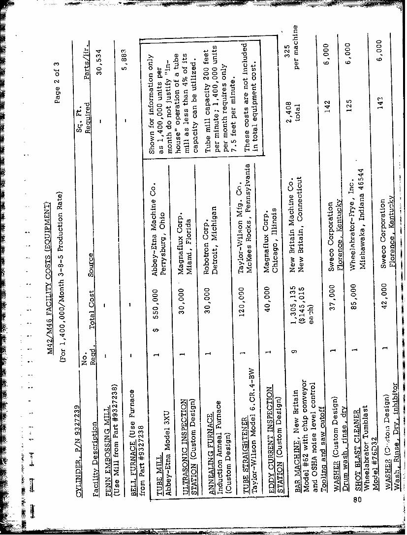
- -O (a) C 0C
NT Ucgi 4J 0 0)QCA4 CY) OD dU) CY C)OD 4- LO (
o- U") 0 s. ~ ~ > 04.(10 fu a) 0 N 00-4 4
4J 41) _4>1C: 4
0)-- 4)5- U2'-(I)
00
0 ) C>, 0-c o 0i --4 4) T$) 41'
41 U) 005.t, ..
0)0
44-.L
0C) I
4-4 - 1CL0
.4--400
40 0 CL0 0 )~~
(E)0 4 0-4 -.- 0wu4 -4 x
o 4-S 4-4 4-
0 u c c 0C Ic a)SJ~0 -4(
-4 4 0
E-1 I1-. -0 080
C/

-- = __ _ __ _ ___ ___ ____
CC)C
C)' C) j 0 00Co 27) 2)ELE
-~ C,
I 4J
0-0: CD >LO- 13 C0 O s
E0 &- C0- 0 0s:.g0 0o 0IZ aiU) )
40 0 C
00
0 =0~~ 00
0~ N4.0)
0 4m Z... C
5-.0 co o D (
-44N 0
U) 4- 0 o
0L~ EL. 0 iwi 0i
000L L) 4)
0cf 0
~~rrA4 rL4 81
4_J7_