Final Report on Case Study Development
103
Project IST-511599 RODIN “Rigorous Open Development Environment for Complex Systems” RODIN Deliverable D26 Final Report on Case Study Development Editor: Elena Troubitsyna (Aabo Akademi University, Finland) Public Document 30 th October 2007 http://rodin.cs.ncl.ac.uk/
Transcript of Final Report on Case Study Development

Project IST-511599
RODIN “Rigorous Open Development Environment for Complex Systems”
RODIN Deliverable D26
Final Report on Case Study Development
Editor: Elena Troubitsyna (Aabo Akademi University, Finland)
Public Document
30th October 2007
http://rodin.cs.ncl.ac.uk/

Contributors:
Budi Arief (University of Newcastle upon Tyne, UK), Michael Butler(University of Southampton, UK), Alex Iliasov (University of Newcastle upon Tyne, UK), Dubravka Ilic (Aabo Akademi University, Finland), Ian Johnson (ATEC Engine Controls Ltd, UK), Maciej Koutny(University of Newcastle upon Tyne, UK) Linas Laibinis (Aabo Akademi University, Finland), Sari Leppänen (Nokia, Finland), Qaisar Malik (Aabo Akademi University, Finland),
Mats Neovius (Aabo Akademi University, Finland), Ian Oliver (Nokia, Finland), Mike Poppleton (University of Southampton, UK),
Abdolbaghi Rezazadeh (University of Southampton, UK), Alexander Romanovsky (University of Newcastle upon Tyne, UK), Kaisa Sere (Aabo Akademi University, Finland), Colin Snook (University of Southampton, UK), Jenny Sorge(University of Southampton, UK), Elena Troubitsyna (Aabo Akademi University, Finland)

CONTENTS 1 Introduction 4 2 Case Study 1 -- Formal Approaches to Protocol Engineering 6 3 Case Study 2 -- Engine Failure Management System 304 Case study 3 -- Formal Techniques within an MDA Context 815 Case study 4 -- CDIS Air Traffic Control Display System 886 Case study 5 -- Ambient Campus 97

SECTION 1. INTRODUCTION
This document reports on the final year of the development of case studies in RODIN and overviews the results achieved in the duration of the overall project. The case studies drive the development of the RODIN methodology and supporting platform, validate it and evaluate its cost-effectiveness. In this deliverable we describe the results achieved in the project and especially over the last year. In general, the development of the case studies has proceeded according to the original plan. Each of the case studies has contributed to the development of both the methodology and the supporting platform. The methodological issues identified earlier have been addressed and expected results achieved. In the third year, the special emphasis was put on validating the tool platform and integration of plug-ins according to the integration plan produced after second review. In Section 2 we describe the advances made in the development of case study 1 – Formal Approaches to Protocol Engineering. The case study investigates the use of formal methods in model-driven development of communicating systems and communication protocols. Over the last year this work was proceeding in two major directions – enhancement of formalized development method Lyra and increasing the degree of automation in Lyra development flow. We describe the work on augmenting Lyra with reasoning about parallelism in service-provision. Moreover, we present the integration plan which was created to increase the level of automation in Lyra and describe the advances made in integrating model-based testing in the development flow. Finally, we give a brief account of overall results of the case study development. Section 3 presents the progress achieved in case study 2 – Engine Failure Management System. The aim of the case study is to study how the methods and tools developed in RODIN could improve design, maintenance and re-use of the failure management systems developed by ATEC. Over the last year the work on development, instantiation and reuse of the generic model has continued. It has put forward development of the plug-in “Context Manader” and integration with the classical development of Failure Management System done by refinement in B. Moreover, another trial system was developed by an application of RODIN methods and tools. During year three the main focus of this case study has been on validation of the RODIN platform, tools and methods in the context of the MDA framework. In Section 4 we describe the developments in case study 3 – Formal Techniques within MDA Context. In the third year we have further investigated how the RODIN techniques and tools can be applied in a model based environment and work flow by using them to develop of a hardware based mobile phone platform NoTA. The significant efforts were put on validation of the RODIN platform and finalizing the results of the case study. . In Section 5 we give an overview of work on case study 4 – CDIS Air Traffic Control
4

Display System. The major problem spotted in the CDIS development a decade ago was a poor comprehensiveness of the formal specification and lack of continuity from the specification to design. In the final year of the project the formal specification developed during the first two years was ported into RODIN platform. Furthermore, additional refinement steps were performed to obtain a realistic distributed specification of the system. Finally, in section 6 we reflect on the experience gained during the final year of work on case study 5 – Ambient Campus. The aim of this case study is to investigate the use of formal methods combined with advanced fault tolerance techniques in developing highly dependable ambient intelligence applications. During year three we have developed a set of abstract specification and refinement patterns that provide general guidance during a formal development and considerably reduce development costs. Refinement patterns are in fact formally described reusable model transformation rules. Moreover, the case study has been the major driver for the development of Mobility Checker plug-in. In general, we believe that the work on the case studies has provided the project partners with strong basis for developing RODIN methods and tools. The case studies have successfully fulfilled their mission – to serve as research drivers.
5

SECTION 2. CASE STUDY 1:FORMAL APPROACHES IN PROTOCOL ENGINEERING
2.1 Introduction
This section summarises the developments of Case study 1 – “Formal Approaches inProtocol Engineering” – during the third year of the RODIN project. In addition, wepresent an overview of the achievements of of the case study during the whole project.
The goal of CS1 is to investigate the application of formal methods for developmentof telecommunication systems and communicating protocols[2.11]. In particular, thework on the case study focuses on formalisation and verification of the service-orienteddesign method Lyra developed in the Nokia research center. Within RODIN, we aimat providing support (in the form of formal techniques and tools) for various stages ofthis approach.
During the first year of the RODIN project we have developed formal specification andrefinement patterns reflecting essential Lyra models and transformations. This allowedus to conduct verification of the Lyra development using stepwise refinement in the BMethod. This work has been reported in [2.5,2.10].
During the second year of the RODIN project we have extended our developed speci-fication and refinement patterns by incorporating fault tolerance mechanisms into theformalized Lyra development flow [2.4]. At the same time, we have developed an ap-proach to verifying the structural consistency of the provided Lyra UML models [2.6].Also, a preliminary methodology for model-based testing ofLyra B models [2.12] hasbeen created.
In the final year of the RODIN project, we have worked on the following directions:
1. Enhancing formalised Lyra development flow by modelling parallel execution ofservices [2.2];
2. Using external tools to provide automatic translation ofLyra UML models intoB models of the RODIN platform;
3. Extending our approach to verifying the structural consistency of the providedLyra UML models by creating the Lyra profile;
4. Further developing the theoretical basis for model-based testing of Lyra Bmodels [2.8].
6

The work on CS1 in year 3 has been presented in a series of internal RODIN workshopsand presentations listed below.
• Presentation at Turku plenary meeting (September 2006);
• Presentation to EU commission (October 2006);
• Presentation at Winchester plenary meeting (April 2007);
• Two presentations at Oxford RODIN workshop on Methodology and Tools forFault Tolerance (MemoT’07), associated with the Integrated Formal Methods(IFM’07) conference (July 2007).
The latter presentations are published as paper in the workshop proceedings [2.2,2.8].
2.2 Methodological Issues and Advances of the Case Study
2.2.1 Integration Plan
Next we describe the contribution of the case study to methodology and plug-in devel-opment achieved in the third year of the RODIN project. During this year our workhas focused on the taskT1.1.5 formulated in the Description of Work:
T1.1.5Investigate how formal and semiformal design techniques can be combined andused to support integration with the targeted platform. Usethe developed plug-ins totackle various problems of the development.
During the first two years of RODIN our worked has progressed in a few separatedirections, yet staying within the main goal – to provide support (in the form of formaltechniques and tools) for the Lyra approach. Namely, the main achieved results are:
1. Lyra UML profile, allowing to check adherence of Lyra UML models to prede-fined architectural rules;
2. Formalisation and verification of additional conditionsneeded to guarantee struc-tural consistency within and between different Lyra phases;
3. Specification and refinement patterns allowing to verify Lyra decomposition anddistribution phases as refinement steps in B;
4. Templates for introducing fault tolerance mechanisms into Lyra B models;
5. The scenario-based approach of model-based testing of Lyra models.
7

Fig. 2.1: Automated system design flow: tool-chain for Lyra-B integration
In the final year we have aimed to integrate those separate results into a tool chain thatcreates an automated system design flow for Lyra. As a result,the following integrationplan was developed (seeFig.2.1).
According to the plan, the Lyra UML models are used as input for the created toolchain. These models are translated (using the external ATL tool) into Event-B modelsof the Rodin platform. The developed Lyra profile together with additional consistencyconditions are used to direct the translation process. Currently, the ATL tool is not fullyintegrated with the RODIN platform. However, its produced outputs (Event-B models)can be directly used as inputs for the platform and plug-ins.
The Event-B models are then further enhanced by the fault tolerance mechanisms,the information of which is provided by the developers. Thisinformation is used toinstantiate the predefined templates for fault tolerance. The B refinement process isused to verify the correctness of the service decompositionand distribution phases aswell as the incorporated fault tolerance mechanisms. The predefined specification andrefinement patterns are employed here to automate the process.
Alternatively, the derived Event-B models could possibly serve as specifications neededfor model-based testing. The test cases can be generated from these models from dif-ferent abstraction levels and used then to test and verify the corresponding implemen-tations.
8

We now present the results achieved during the third year of RODIN in more detail.At the same time, we relate them with the methodological tasks for the case studyformulated in the Description of Work [2.11]. Some of these results were directlyinfluenced by the integration plan. Others are enhancementsof the results presentedearlier.
2.2.2 Ensuring Consistency of Lyra UML models
To automate the Lyra design flow, we need to know the precise form and structure ofLyra UML models that are used as inputs for our tool chain. Theapproach presentedin this section not only defines a Lyra UML profile supporting the entire Lyra develop-ment but also smoothly integrates formal verification for ensuring model consistency.
Lyra Profile During the RODIN project we (together with Nokia developers) haveworked on finalising the Lyra profile – a UML2 profile that defines the architecturalrules for the Lyra design method. The Lyra profile has been derived as a result of anumber of large industrial developments conducted according to the Lyra methodologywithin Nokia Research Center.
The profile defines the Lyra-specific modelling concepts and dependencies betweenthem, thus outlining the required stages of the system development. The profile isconsidered to be a reference model using which we could validate created Lyra models.Validation ensures that these models use only concepts defined by the architecturalrules.
To introduce the Lyra profile, we use UML2 as our description language. This al-lows us to avoid unnecessary redefinitions since most elements of Lyra models reuseexisting UML2 notions.
The aim of the Lyra profile is to tailor the existing UML2 metamodel to the Lyra de-sign method. We customize the UML2 metamodel by introducingspecific stereotypes.They allow us to use the Lyra concepts in modelling and add corresponding seman-tics to the metamodel. Namely, each Lyra stereotype allows us to use a specific Lyraelement while modelling either system structure or behaviour.
While presenting the profile, we show Lyra stereotypes as extensions of the corre-sponding UML2 meta-classes. For clarity, we show only the associations betweenstereotypes and omit the corresponding meta-associationsbetween the extended meta-classes.
A summary of the Lyra profile is presented on the next page.
9

Behavior <<metaclass>>
StateMachine <<metaclass>>
Actor <<metaclass>>
LyraActor
SAP
USAP PSAP PeerAP
InternalBehavior AccessPointCommunication
InternalComputation ExecutionControl SAPCommunication
USAPCommunication PSAPCommunication PeerCommunication
BehavioredClassifier <<metaclass>>
ServiceComponentBehavior
Port<<metaclass>>
EncapsulatedClassifier <<metaclass>>
AccessPoint ServiceBehavior
ServiceComponent0..1
0..1 0..1
+classifierBehavior 0..1
*
*
*
+ownedServiceComponentPort*
*
+context
+ownedBehavior *
ServiceUser ServiceProvider
Interface<<metaclass>>
*+implement
* *+use
*
*
+required *
*
+provided
*
SystemComponent
**+ownedPort
*
+ownedServiceComponent
**
+ownedSystemComponent*
10

Defining consistency in Lyra The Lyra design method adopts the top-down devel-opment paradigm. Development starts from a high level of abstraction. The modelsat each subsequent stage represent the system at lower levels of abstraction, i.e., theyspecify the required functionality in more detail. This raises a problem of ensuringmodel consistency, throughout the system development. In other words, we have toguarantee that each properly defined model is not contradictory with already createdmodels. We call a model properly defined if it satisfies the model presentation rules,i.e., the structural requirements imposed on the modellingelements.
Ensuring consistency is a two-fold task. On the one hand, a model should be con-sistent with the models at the same development stage. On theother hand, it shouldbe also consistent with the models from the previous development stages. The con-sistency between the concepts specifying different aspects of the system structure andbehaviour on the same development stage is known as intra-consistency; whereas theinter-consistency is defined as the consistency among modelling concepts from differ-ent development stages.
The Lyra profile presented in the previous section allows us only to ensure that createdLyra models are properly defined, i.e., that their structureconforms to the one definedin the profile. Defining consistency in the Lyra profile is, however, a difficult task.Although one could express intra-consistency rules as OCL constraints on the profileelements, it would still require referencing those UML2 meta-classes extended by theprofile stereotypes. This would complicate the process of creating OCL constraints.Furthermore, Lyra is based on stage-specific development, which requires to maintainconsistency between Lyra model elements from different stages.
To summarize, the overall Lyra design flow is guided by the requirements imposed onits modelling elements:
1. each model is created according to certain structural requirements;
2. models within one stage are created according to the defined intra-consistencyrules;
3. models at each subsequent development stage preserve theinter-consistencyrules.
We start formal verification of consistency by deriving the list of informal require-ments for Lyra UML models. In particular, for each Lyra stagewe derive the list ofrequirements corresponding to a particular Lyra model. Foreach model we group re-quirements around concrete model elements. Once the complete list of requirements isobtained, we can distinguish between model-presentation,intra-, and inter-consistencyrules for each particular Lyra model.
11

The informal requirements form the basis for formalizing Lyra models and consistencyrules in B. For each Lyra model we introduce the corresponding B machine specifyingthe way the model is constructed. The B machines are created in the order definedby the Lyra development flow. The intra-consistency rules are defined as invariantproperties of the corresponding machines. The models at each subsequent stage arerepresented in the same way. Moreover, inter-consistency is ensured by refinementbetween the corresponding specifications, i.e., he gluing refinement relation containsinter-consistency conditions between the corresponding stages.
This work allowed us to establish consistency between the Lyra UML2 models whileundertaking the Lyra development, which otherwise we couldnot achieve within theprofile solely. While verifying the Lyra development flow, wesimulated Lyra develop-ment and formalized both the Lyra models and the intra- and inter-consistency rules inB. The details of the suggested structure of B models and the refinement process werealready reported in D18 [2.9].
This work has contributed toT2.1 [2.11].
2.2.3 Translation of Lyra UML models into Event-B
The Lyra profile and consistency conditions of Lyra models are used to direct auto-matic translation Lyra UML models into the corresponding Event-B specifications.The translation is accomplished by employing an external tool ATL based on AtlasTransformation Language.
Lyra UML models are created by conforming them to the provided Lyra profile. Inorder to formalise these models by transforming them into Event-B, we employ AtlasTransformation Language (ATL) tool support. In general, ATL introduces a set oftransformation concepts that make it possible to describe model transformations.
The ATL language is a model transformation language with a means to specify theway to produce a number of target models from a set of source models. The ATLlanguage is a hybrid of declarative and imperative programming. An ATL transforma-tion program is composed of rules that define how source modelelements are matchedand navigated to create and initialize the elements of the target models. Besides basicmodel transformations, ATL defines an additional model querying facility that enablesto specify requests onto models. ATL also allows code factorization through the def-inition of ATL libraries. The ATL Integrated Development Environment ((IDE) isdeveloped over the Eclipse platform, thus making it possible to integrate with RODINplatform which is also based on Eclipse.
The models constitute the basic pieces of the model-driven architecture. Indeed, in
12

the field of model-driven engineering (MDE), a model is defined according to the se-mantics of a model of models, also called a metamodel. A modelthat respects thesemantics defined by a metamodel is said to conform to this metamodel. A metamodelis in itself a model. This implies for it to conform to its own metamodel. To this end,the model-driven architecture defines a third modelling level which corresponds to themetametamodel, as illustrated in Fig.2.2.
Fig. 2.2: The model-driven architecture
A metametamodel aims to introduce the semantics that are required to specify meta-models. As a model with its metamodel, a metamodel conforms to the metameta-model. A metametamodel is usually self-defined, which meansthat it can be specifiedby means of its own semantics. In such a case, a metametamodelconforms to itself.
Several metametamodel technologies are available. The ATLtransformation enginecurrently provides support for two of these existing technologies: the Meta Object Fa-cilities (MOF 1.4) defined by the OMG and the Ecore metametamodel defined by theEclipse Modelling Framework (EMF). This means that ATL is able to handle meta-models that have been specified according to either the MOF orthe Ecore semantics.
In the scope of model-driven engineering, model transformation aims to provide amean to specify the way to produce target models from a numberof source models.For this purpose, it should enable developers to define the way source model elementsmust be matched and navigated in order to initialize the target model elements.
Formally, a simple model transformation has to define the wayfor generating a modelMb, conforming to a metamodelMMb, from a modelMa conforming to a metamodelMMa. A major feature in model engineering is to consider, as far as possible, allhandled items as models. The model transformation itself therefore has to be defined asa model. This transformation model has to conform to a transformation metamodel thatdefines the model transformation semantics. As other metamodels, the transformationmetamodel has, in turn, to conform to the considered metametamodel.
13
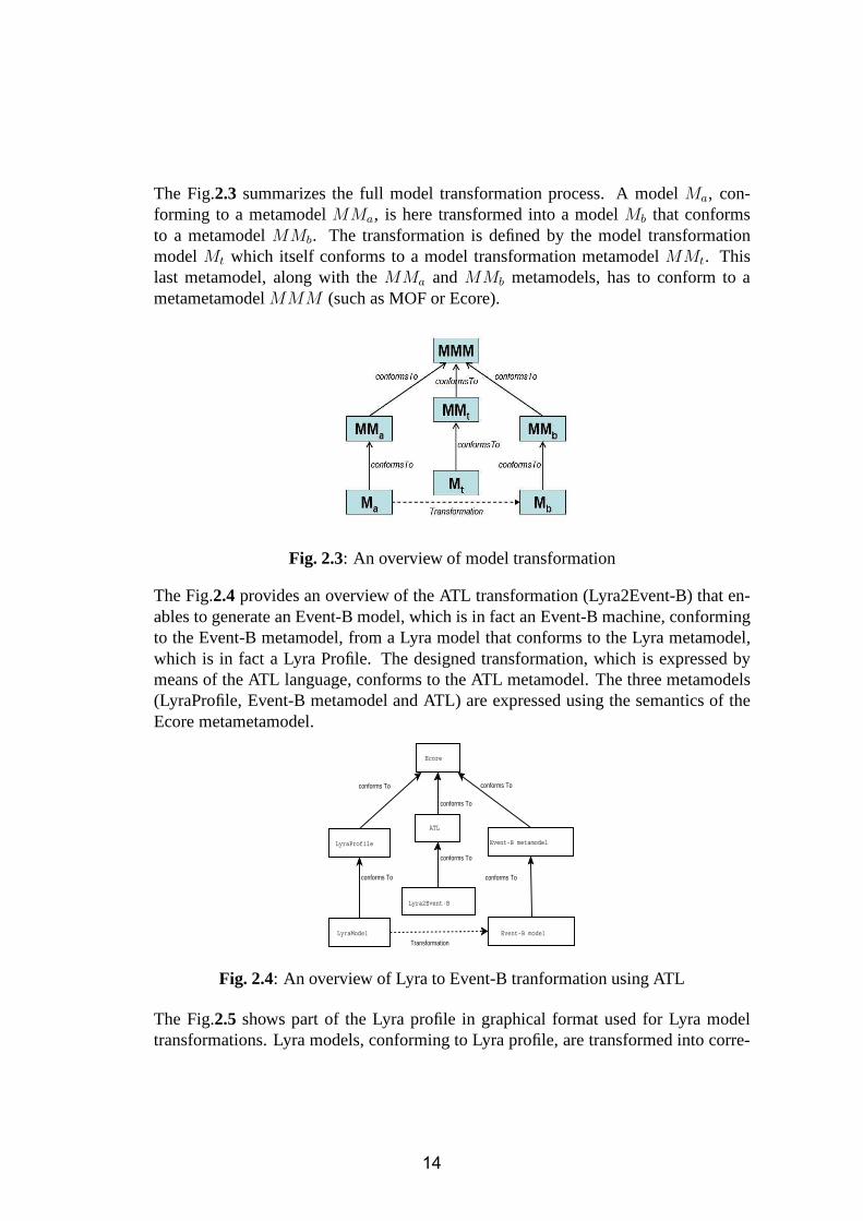
The Fig.2.3 summarizes the full model transformation process. A modelMa, con-forming to a metamodelMMa, is here transformed into a modelMb that conformsto a metamodelMMb. The transformation is defined by the model transformationmodelMt which itself conforms to a model transformation metamodelMMt. Thislast metamodel, along with theMMa and MMb metamodels, has to conform to ametametamodelMMM (such as MOF or Ecore).
Fig. 2.3: An overview of model transformation
The Fig.2.4 provides an overview of the ATL transformation (Lyra2Event-B) that en-ables to generate an Event-B model, which is in fact an Event-B machine, conformingto the Event-B metamodel, from a Lyra model that conforms to the Lyra metamodel,which is in fact a Lyra Profile. The designed transformation,which is expressed bymeans of the ATL language, conforms to the ATL metamodel. Thethree metamodels(LyraProfile, Event-B metamodel and ATL) are expressed using the semantics of theEcore metametamodel.
Ecore
ATL
Lyra2Event-B
LyraProfile
LyraModel
Event-B metamodel
Event-B model
conforms To
conforms To conforms To
conforms To
conforms To
conforms To
Transformation
Fig. 2.4: An overview of Lyra to Event-B tranformation using ATL
The Fig.2.5 shows part of the Lyra profile in graphical format used for Lyra modeltransformations. Lyra models, conforming to Lyra profile, are transformed into corre-
14

sponding Event-B machines which conforms to Event-B metamodel shown in Fig.2.6.These transformations are directed by using special rules written in the ATL language.The rules define the exact way Lyra UML elements should be translated into the cor-responding elements of Event-B.
Fig. 2.5: Part of Lyra Profile used for trannsformation
This work has contributed toT2.1 [2.11].
2.2.4 Introducing Parallelism into the Lyra Development Flow
In our previous work [2.3, 2.5] we proposed a set of formal specification and refine-ment patterns reflecting the essential models and transformations of Lyra. Moreover, toachieve system fault tolerance, we extended Lyra to integrate modelling of fault toler-ance mechanisms into the entire development flow. We demonstrated how to formallyspecify error recovery by rollbacks as well as reason about error recovery termination.
During the third year of RODIN we have extended our Lyra formalisation to modelparallel execution of services. In particular, such an extension affected the fault tol-erance mechanisms incorporated into our formal models. Theextension makes ourformal models more complicated. However, it also gives us more flexibility in choos-ing possible recovery actions.
Introducing Fault Tolerance in the Lyra Development Flow The Lyra service ex-ecution flow is tightly connected with the introduced fault tolerance mechanisms. Be-
15

Fig. 2.6: Event-B metamodel used for tranformation
fore extending our model with parallel execution of services, let us briefly remind howfault tolerance mechanisms are modelled in the formalised Lyra development.
In the LyraService Decompositionphase, the top service is decomposed into a numberof stages (subservices). The service component can executecertain subservices itselfas well as request other service components to do it. According to Lyra, the flow of theservice execution is managed by a special service componentcalledService Director.Service Directorco-ordinates the execution flow by enquiring the required subservicesfrom the external service components.
In general, execution of any stage of a service can fail. In its turn, this might lead tofailure of the entire service provision. Therefore, while specifying Service Director,we should ensure that it does not only orchestrates the fault-free execution flow butalso handles erroneous situations. Indeed, as a result of requesting a particular subser-vice,Service Directorcan obtain a normal response containing the requested data or anotification about an error. As a reaction to the occurred error, Service Directormight
• retry the execution of the failed subservice,
• repeat the execution of several previous subservices (i.e., roll back in the serviceexecution flow) and then retry the failed subservice,
• abort the execution of the entire service.
The reaction ofService Directordepends on the criticality of an occurred error: themore critical is the error, the larger part of the execution flow has to be involved in the
16

SS1 SS2 SS3 SSN-1 SSN
S
(a) Fault free execution flow
SS1 SS2 SS3 SSN-1 SSN
S
Retry
(b) Error recovery by retrying execution of afailed subservice
SS1 SS2 SS3 SSN-1 SSN
S
Rollback
(c) Error recovery by rollbacks
SS1 SS2 SS3 SSN-1 SSN
S
Unrecoverable error
Success
Service failure
(d) Aborting service execution
SS1 SS2 SS3 SSN-1 SSN
S
Success
Service failure
Execution_time > Max_SRT
(e) Aborting the service due to timeout
Fig. 2.7: Service decomposition: faults in the execution flow
error recovery. Moreover, the most critical (i.e., unrecoverable) errors lead to abortingthe entire service. InFig.2.7(a)we illustrate a fault free execution of the serviceScomposed of subservicesS1, . . . , SN . Different error recovery mechanisms used inthe presence of errors are shown inFig.2.7(b) - 2.7(d).
Let us observe that each service should be provided within a certain finite period oftime – themaximal service response time MaxSRT. In our model this time is passedas a parameter of the service request. Since each attempt of subservice executiontakes some time, the service execution might be aborted evenif only recoverable errorshave occurred but the overall service execution time has already exceededMax SRT.Therefore, by introducingMax SRTin our model, we also guarantee termination oferror recovery, i.e., disallow infinite retries and rollbacks, as shown inFig.2.7(e). Moredetails on error recovery mechanisms can be found in [2.3].
Modelling Parallel Execution Flow Our formal model briefly described in the pre-vious section assumes sequential execution of subservices. However, in practice, someof subservices can be executed in parallel. Such simultaneous service execution di-rectly affects the fault tolerance mechanisms incorporated into our B models. As a re-sult, they become more complicated. However, at the same time it provides additional,more flexible options for error recovery that can be attempted byService Director. The
17

approach briefly presented below was published in [2.2].
The information about all subservices and their required execution order becomesavailable at the Service Decomposition phase. This knowledge can be formalised as adata structure
Task : seq(P(SERV ICE))
HereSERV ICE is a set of all possible subservices. Hence,Task is defined as asequence of subsets of subservices. It basically describesthe control flow for the topservice in terms of required subservices. At the same time, it also indicates whichsubservices can be executed in parallel.
For example,Task = < {S1, S2}, {S3, S4, S5}, {S6} >
defines the top service as a task that should start by executing the servicesS1 andS2 (possibly in parallel), then continuing by executing the servicesS3, S4, andS5(simultaneously, if possible), and, finally, finishing the task by executing the serviceS6.
Essentially, the sequenceTask defines the data dependencies between subservices.Also, Task can be considered as the most liberal (from point of view of parallel ex-ecution) model of service execution. In the Service Distribution phase the knowledgeabout the given network architecture becomes available. This can reduce the paral-lelism of service control flow by making certain services that can be executed in par-allel to be executed in a particular order enforced by the provided architecture.
Therefore,Task is basically the desired model of service execution that will serve asthe reference point for our formal development. The actual service execution flow ismodelled in by the sequenceNext which is of the same type asTask:
Next : seq(P(SERV ICE))
Since at the Service Decomposition phase we do not know anything about future ser-vice distribution,Next is modelled as an abstract function (sequence), i.e., withoutgiving its exact definition. However, it should be compatible with Task. More pre-cisely, ifTask requires that certain servicesSi andSj should be executed in a particularorder, this order should be preserved in the sequenceNext. However,Next can splitparallel execution of given services (allowed byTask) by sequentially executing themin any order.
So the sequenceNext abstractly models the actual control flow of the top service.Itis fully defined (instantiated) only in the refinement step corresponding to the ServiceDistribution phase. For example, the following instantiation of Next would be correctwith respect toTask defined above:
Next = < {S2}, {S1}, {S4}, {S3, S5}, {S6} >
18

Also, we have to take into account thatService Directoritself can become distributed,i.e., different parts of service execution could be orchestrated by distinct service di-rectors residing on different network elements. In that case, for every service director,there is a separateNext sequence modelling the corresponding part of the service ex-ecution flow. All these control flows should complement each other and also be com-patible withTask. To ensure this compatibility, additional properties are required,connecting theTask andNext sequences.
Modelling Recovery Actions As we described before, aService Directoris the ser-vice component responsible for orchestrating service execution. It monitors executionof the activated subservices and attempts different possible recovery actions when theseservices fail. Obviously, introducing parallel executionof subservices (described in theprevious subsection) directly affects the behaviour ofService Director.
Now, at each execution step in the service execution flow, several subservices can beactivated and run simultaneously.Service Directorshould monitor their execution andreact asynchronously whenever any of these services sends its response. This responsecan indicate either success or a failure of the corresponding subservice.
The sequential formal model for fault tolerance (seeFig.2.7) is still valid. However,taking into account parallel execution of services presents Service Directorwith newoptions for its recovery actions. For example, getting response from one of activesubservices may mean that some or all of the remaining activesubservices shouldbe stopped (i.e., interrupted). Also, some of the old recovery action (like retrying ofservice execution) are now parameterised with a set of subservices. The parameterindicates which subservices should be affected by the corresponding recovery actions.
Below we present the current full list of actions thatService Directormay take afterit receives and analyses the response from any of active subservices. Consequently,Service Directormight
• Continue to the next service execution step. In case of successful termination ofall involved subservices (complete success).
• Wait for response from the remaining active subservices. In caseof successfultermination of one of few active subservices (partial success).
• Abort the entire service and send the corresponding message to theuser or re-questing component. In case of an unrecoverable error or theservice timeout.
• Cancel(a set of subservices) by sending the corresponding requests to interrupttheir execution (partial abort). In case of a failure which requires to retry orrollback in the service execution flow.
19

• Retry (a set of subservices) by sending the corresponding requests to re-executethe corresponding subservices. In case of a recoverable failure.
• Rollback to a certain point of the service execution flow. In case of a recoverablefailure.
Service Directormakes its decision using special abstract functions neededfor evalu-ating responses from service components. These functions should be supplied (instan-tiated) by the system developers at a certain point of systemdevelopment.
Here is a small excerpt from the B specification ofService Directorspecifying the partwhere it evaluates a response and decides on the next step:
handle =
...
resp := Eval(curr task, curr state);
CASE resp OF EITHER
CONTINUE THEN
IF curr task = size(Next) THEN finished := TRUE
ELSE active serv, curr task := Next(curr task + 1), curr task + 1 END
WAIT THEN skip
RETRY THEN active serv := active serv ∪ Retry(curr task, curr state)
CANCEL THEN active serv := active serv ∪ Cancel(curr task, curr state)
ROLLBACK THEN curr task := Rollback(...); active serv := Next(curr task)
ABORT THEN finished := TRUE
END
...
where the abstract functionsNext, Retry, Cancel, andRollback are defined (typed)as follows:
Next : seq(P(SERVICE))
Eval : 1..size(Next) ∗ STATE → {SUCCESS,WAIT,RETRY,CANCEL,ROLLBACK,ABORT}
Retry : 1..size(Next) ∗ STATE 7→ P(SERVICE)
Cancel : 1..size(Next) ∗ STATE 7→ P(SERVICE)
Rollback : 2..size(Next) ∗ STATE 7→ 1..size(Next) − 1
20

Translating to Event-B The formal development described above has been origi-nally carried out in Classical B, using Atelier-B as the toolsupport. During the thirdyear we moved this development into Event-B and the RODIN platform. Of course,it has required certain changes in the B models. For example,sequences has to bemodelled as special kind of total functions.
The main changes were influenced by the fact that Event-B doesnot support sequentialcomposition or any kind of conditional branching inside of the operation bodies. Thishas resulted in splitting more such more complicated operations into several smallerones responsible for particular branch or step in the execution flow. Thehandle oper-ation shown above has to be splitted into 7 smaller events. The examples of three ofthem (forRETRY, WAIT , andABORT branches) are shown below.
EVENT handle RETRYWHEN
grd1 : ¬ (in data = NIL) ∧ finished = FALSE ∧ changed = TRUE
grd2 : Eval(curr task 7→ curr state) = RETRY
grd3 : time left < old time left
THENact1 : active serv := active serv ∪ Repeat(curr task 7→ curr state)act3 : old time left := time left
act2 : resp := RETRY
END
EVENT handle WAITWHEN
grd1 : ¬ (in data = NIL) ∧ finished = FALSE ∧ changed = TRUE
grd2 : Eval(curr task 7→ curr state) = WAIT ...
THENact3 : old time left := time left
act4 : resp := WAIT
END
EVENT handle ABORTWHEN
grd1 : ¬ (in data = NIL) ∧ finished = FALSE ∧ changed = TRUE
grd2 : Eval(curr task 7→ curr state) = ABORT ...
THENact1 : finished := TRUE
act3 : old time left := time left
act2 : resp := ABORT
END
21

This work has contributed toT2.1, T2.3, andT2.4 [2.11].
2.2.5 Model-based Testing Using Scenarios and Event-B Refinements
The B specifications of the formalised Lyra development can also be used as modelsfrom which we can generate test-cases for the correspondingimplementations. Thisis often referred to asmodel-based testing. In this section, we present our work on amodel-based testing approach based on user-provided testing scenarios. The presentedapproach was published in [2.8].
Generally, implementation code for a system-under-test (SUT) can be generated froma sufficiently detailed specification. But often, due to the remaining abstraction gapbetween a model and the implementation, it is not always feasible to generate im-plementation code. As a result, the implementation is not shown to be correct byconstruction but instead it is hand-coded by programmer(s). Identifying and writingtesting scenarios for such an implementation is a very time consuming and error-proneprocess. In our approach, test scenarios are identified at anabstract specification leveland are automatically refined (together with a specification) at each refinement step.These scenarios can also include tests of the incorporated fault tolerance mechanisms.The test scenarios are represented as Communicating Sequential Process (CSP) expres-sions. In the final step, executable test cases are generatedfrom these CSP expressionsto be tested on SUT.
Refinement of Event-Based SystemsWe are interested how refinement affects theexternal behavior of a system under construction. Such external behavior can be rep-resented as a trace of observable events, which then can be used to produce test cases.From this point of view, we can distinguish two different types of refinement calledatomicityrefinement andsuperpositionrefinement.In Atomicity refinement, one event operation is replaced by several operations, de-scribing the system reactions in different circumstances the event occurs. Intuitively, itcorresponds to a branching in the control flow of the system asshown inFig.2.8(a).
In Superposition refinement, new implementation details are introduced intothe sys-tem in the the form of new events that were invisible in the previous specification.These new events can not affect the variables of the abstractspecification and onlydefine computations on newly introduced variables. For our purposes, it is convenientto further distinguish two basic kinds of superposition refinement, where
• a non-looping event is introduced,
22

• a looping but terminating event is introduced.
These two types of refinements are graphically shown inFig.2.8(b) and (c).
Let us note that the presented set of refined types is by no means complete. However,it is sufficient for our approach based on user defined scenarios.
EE1
E2
EE1E
EE
(a)
(b)
(c)
E1
Fig. 2.8: Basic refinement transformations
Scenario-based approach for testing We use the termscenarioto represent atestscenariofor our system under test (SUT). A test scenario is one of possible validexecution paths that the system can follow. In other words, it is one of expected func-tionalities of the system. For example, in a hotel reservation system, booking a roomis one functionality, while canceling a pre-booked room is another one. In this article,we use both terms functionality and scenario interchangeably.
Each scenario usually includes more than one system-level procedure/event, whichare executed in some particular sequence. In a non-trivial system, identifying such asequence may not be an easy task. Our testing approach is based on stepwise systemdevelopment, where an abstract model is first constructed and then further refined toinclude more details (e.g., functionalities) of the system. On the abstract level, an initialscenario is provided by the user. Afterwards, for each refinement step, scenarios arerefined automatically. InFig.2.9, an abstract modelMi is refined byMi+1 (denotedby Mi ⊑ Mi+1). ScenarioSi is an abstract scenario, formally satisfiable(|=) byspecification modelMi, provided by the user. In the next refinement step, scenarioSi+1
is constructed automatically fromMi, Mi+1 andSi in such a way thatSi+1 formallysatisfies modelMi+1.
Each scenario can be represented as a Communicating Sequential Process (CSP) [?]expression. Since we develop our system in a controlled way,i.e. using basic re-finement transformations described in Section 2.2.5, we canassociate these Event-B refinements with syntactic transformations of the corresponding CSP expressions.Therefore, knowing the way modelMi was refined byMi+1, we can automatically
23

SUT Test cases
S i
Si+1
Si+n
T
T
M i
Mi+1
Mi+n
Test implementation
System implementation
Test application
Fig. 2.9: Overview of our Model-based testing approach
refine scenarioSi into Si+1. To check whether a scenarioSi is a valid scenario of itsmodelMi, i.e., modelMi satisfies(|=) scenarioSi, we use Pro-B model checker [2.7].Pro-B supports execution (animation) of Event-B specifications, guided by CSP ex-pressions. The satisfiability check is performed at each refinement level as shown intheFig.2.9. The refinement of scenarioSi is the CSP trace-refinement denoted by⊑T .
After the final refinement, the system is implemented from themodelMi+n. Thisimplementation is calledsystem under test (SUT). The scenarioSi+n, expressed asa CSP expression, is unfolded into the executable test casesthat are then applied toSUT. The unfolding of scenarios into test cases is a process that is very similar tosystem simulation. During this process, an Event-B model isinitialised and executed,which being guided by the provided scenarios. For our approach, we use Pro-B modelchecker,which has the functionality to animate B specifications guided by the providedCSP expression. After the execution of each event, present in the scenario, informationabout the changed system state is stored.
In other words, the execution trace is represented by a sequence of pairs< e, s >,wheree is an event ands is a post-state (the state after execution of evente). Fromnow on we will refer to a single pair< e, s > as anESPair.
For a finite number of eventse1, e2.....en, present both in the modelM and the SystemUnder Test (SUT), a test caset of length n consists of an initial stateINIT and asequence ofESPairs
t = INIT, {< e1, s1 >, < e2, s2 >, ....... < en, sn >}
Similarly, a scenario is formally defined as finite set of related test cases, i.e., scenarioS = {t1, t2, .., tn}. As mentioned earlier,ESPair relates an event with its post-state.This information is stored during test-case generation. For SUT these stored post-states become expected outputs of the system and act as averdict for the testing. After
24

execution of each event, the expected output is compared with the output of the SUT.This comparison is done with the help of probing functions. The probing functions aresuch functions of SUT that at a given point of their invocation, return state of the SUT.For a test-case to pass the test, each output should match theexpected output of therespective event. Otherwise, we conclude that a test case has failed. In the same way,test cases from any refinement step can be used to test implementation as long as boththe implementation and the respective test cases share the same events and signatures.
Integration with the RODIN platform This work is being implemented as a plug-in for the RODIN open-source platform. The Model-based testing(MBT) plug-in isdesigned in such a way that it uses the Pro-B model checker [2.7] plug-in in the back-ground (seeFig.2.10). The Pro-B plug-in is capable of generating execution tracesof the models. It is also used to verify the satisfiability relations between scenariosand their respective models as described above. In order to generate test-cases by theMBT plug-in, the user is first required to prove correctness of the model(s) using theRODIN platform. Additionally, the user has to provide testing scenario(s) for the mostabstract specification model. The MBT plug-in uses the user-provided scenario(s) andthe provided B models to generate test cases. The process canbe then repeated foreach refinement step.
RODIN platform
ProB Plug-inMBT Plug-in
Event-B specifications
Execution traces
Event-B specifications, testing scenarios
Test cases
Fig. 2.10: MBT plug-in design diagram
This work has contributed toT2.1 andT2.3 [2.11].
25

2.3 Impact of the Case Study on the Platform and Plug-inDevelopment
One of the major requirements for our case study was to achieve a high degree of au-tomation of the development process, so that the formal verification process would becarried out in a ’background’ mode. To achieve automation assoon as possible, westarted automated modelling and verification even before the platform has arrived. Wehave conducted the development in the classical B using Atelier B as a tool supportinstead. However, when the platform has arrived, our development was exported to theRODIN platform. We carried out the experiments comparing performance of AtelierB and the platform, i.e., we compared the portion of automated and user-guided proofsrequired to verify our development. As a result of the experiments, we have establishedthat the platform achieves even better performance in termsof the automatically provedproof obligations. However, carrying out user-assisted proofs is currently weaker com-paring to the Atelier B. The types of proof obligations that are less successfully dealtby the platform were identified and reported to the platform developers. Hence weprovided the first-hand experience feedback to the developers.
The goals set for the case study has motivated our work on developing the model-basedtesting plug-in. The theory for model-based testing plug-in is based on user-providedtesting scenarios. It employs the Event-B method as a formalframework supportingstepwise system development by refinement. Formal specifications of case study 1are also developed and refined in a stepwise manner. Moreover, testing of the fault-tolerance mechanisms is one of the main issues in case study 1. Some of the case studymodels, e.g., specifications of service director components, were tested while devel-oping the theoretical basis of model-based testing plug-in. Using the model-basedtesting approach, test scenarios were identified at the abstract specification level andthen refined (together with the corresponding specifications) at each refinement step asshown inFig.2.9. These scenarios also included tests of the incorporated fault toler-ance mechanisms. As a result, the model-based testing technique adapted to stepwisedevelopment of the case study.
2.4 Overview of the Achievements of the Case Study
In three years of our work on the case study, we have achieved the following results:
• Collection of formalised Lyra specification and development patterns reflectingessential Lyra models and development stages;
• Separate verification of syntactic and semantic consistency of Lyra UML modelsand development stages;
26

• Incorporation of fault tolerance mechanisms into the Lyra development flow;
• Theoretical basis for model-based testing of Lyra models;
• Automatic translation of Lyra UML models into the Rodin platform.
Now we will show how our achievements compare with the expected results of thecase study given in the Description of Work [2.11].
Feasibility of incorporating refinement to verify model decomposition The Lyradevelopment flow is based on model decomposition. We have managed to validateLyra development flow by translating it into the corresponding B refinement process,where the essential Lyra service decomposition and distribution transformations areformally verified by proving them as B refinement steps between the corresponding Bmodels. At the same time, the fault tolerance mechanisms areincorporated into Lyra Bmodels. All together, this shows feasibility of incorporating refinement to verify modeldecomposition.
Guidance of combining model-checking with the refinement approach Origi-nally the formal verification in Lyra was based on model-checking approach. However,telecommunication systems and telecommunicating protocols are usually complex anddata intensive. This approach was prone to the state explosion problem. Originallywe planned to integrate model-checking and refinement approaches to avoid state ex-plosion problem while verifying correctness of decomposition. We intended to usemodel-checking to verify conformance of system componentsto certain system-levelproperties. In the duration of work this idea was transformed into the idea of conduct-ing refinement-based model development and decomposition and using the resultingformal model as an input for model-based testing of code implementing these models.
Enhancements of UML to B tools to support formal and semiformal methodsInitially we planned to customize the U2B tool to integrate Lyra-specific modellinginto it. However, this turned out to be a redundant step in thetool chain transformingUML2-based models into Event B. Instead, we discovered the ATL tool which wellfitted to this purpose. Namely, it allowed us directly express translation rules betweenLyra and Event B. Besides, the use of U2B would require redefinition of the developedformal patterns for Lyra development, while ATL preserved them. Moreover, ATLsmoothly integrated our work on Lyra UML profile and inter andintra-consistencyconditions of Lyra UML models into the translation process.
27

Validation of developed open platform and plug-ins Even though the original for-mal development has been conducted using classical B, before the end of the projectall the developed formal models were translated into Event-B and integrated into theRodin platform. Moreover, the ProB plug-in has been used as the back-end for themodel-based plug-in that is being developed within the casestudy.
References
2.1 D. Ilic, S. Leppanen, E. Troubitsyna, and L. Laibinis. Towards AutomatedModel-Driven Development of Distributed Systems and Communicating Proto-cols. TUCS Technical Report 829. Turku Centre for Computer Science. Submit-ted to journalSoftware and Systems Modeling, August 2007.
2.2 L. Laibinis, E. Troubitsyna, and S. Leppanen. Formal Reasoning about Fault Tol-erance and Parallelism in Communicating Systems. Proceedings ofWorkshop onMethods, Models and Tools for Fault Tolerance (MeMoT’07), pp.24–32, Oxford,UK. Technical Report of Newcastle University, July 2007.
2.3 L. Laibinis, E. Troubitsyna, S. Leppanen, J.Lilius, and Q.Malik. Formal Service-Oriented Development of Fault Tolerant Systems.Rigorous Development ofComplex Fault Tolerant Systems. Lecture Notes in Computer Science, Vol.4157,chapter 13, pp.261–287, Springer, August 2006.
2.4 L. Laibinis, E. Troubitsyna, S. Leppanen, J. Lilius, and Q. Malik. For-mal Service-Oriented Development of Fault Tolerant Communicating Systems.TUCS Technical Report 764. Turku Centre for Computer Science, April 2006.
2.5 L. Laibinis, E. Troubitsyna, S. Leppanen, J. Lilius, and Q. Malik. Formal Model-Driven Development of Communicating Systems. Proceedingsof 7th Interna-tional Conference on Formal Engineering Methods (ICFEM’05), LNCS 3785,Springer, November 2005.
2.6 S. Leppanen, D. Ilic, Q. Malik, T. Systa, and E. Troubitsyna. SpecifyingUML Profile for Distributed Communicating Systems and Communication Pro-tocols. Proceedings of Workshop on Consistency in Model Driven Engineering(C@MODE’05), November 2005.
2.7 M. Leuschel and M. Butler. ProB: A model checker for B. In K. Araki, S. Gnesi,and D. Mandrioli, editors,FME 2003: Formal Methods, LNCS 2805, pages 855–874. Springer-Verlag, 2003.
28

2.8 Q. Malik, J. Lilius, and L. Laibinis. Model-based Testing Using Scenarios andEvent-B Refinements. Proceedings ofWorkshop on Methods, Models and Toolsfor Fault Tolerance (MeMoT’07), pp.59–69, Oxford, UK. Technical Report ofNewcastle University, July 2007.
2.9 Rigorous Open Development Environment for Complex Systems(RODIN), De-liverable D18, Intermediate Report on Case Study Development. online athttp://rodin.cs.ncl.ac.uk/.
2.10 Rigorous Open Development Environment for Complex Systems(RODIN),Deliverable D8, Initial Report on Case Study Development. online athttp://rodin.cs.ncl.ac.uk/.
2.11 Rigorous Open Development Environment for Complex Systems(RODIN), De-scription of Work. IST FP6 STREP project, online at http://rodin.cs.ncl.ac.uk/.
2.12 M. Satpathy, Q. Malik, and J.Lilius. Synthesis of Scenario Based Test Casesfrom B Models. Proceedings ofFormal Approaches to Software Testing andRuntime Verification, Combined International Workshops FATES 2006 and RV2006, Seatle, USA.Lecture Notes in Computer Science, Vol.4262, pp.133–147,Springer, August 2006.
29

SECTION 3. CASE STUDY 2: ENGINE FAILURE MANAGEMENT SYSTEM
3.1. Introduction This section of the D26 report summarises the developments leading up to and including the final year of the AT Engine Controls (ATEC) case study “Engine Failure Management System” as part of the RODIN project. In addition to the Engine Failure Management system case a second case production acceptance test “PAT” was undertaken in the final year is described later.* The work undertaken since the last interim report D18 [3.7] has been presented to the RODIN project in a series of internal workshops and presentations outlined below.
Presentation on work (Turku Plenary, Sept 2006) A summary of the case study development was presented
Presentation To EU (Brussels Oct 2006)
An industrial evaluation of RODIN case study 2 was presented
Presentation on work internal workshop (Winchester April 2007) A new ATEC case was presented.The FMS case progress was reported.
Presentation on work (Oxford July 2008)
Academic presentation from Aabo on formalising UML based development in fault tolerant systems derived from the FMS case study.
The case study has provided contributions to the following Rodin deliverables in the final year . D26 Final report (this report) D27 Case study demonstrator D28 Assessment of tools and methods. D34 Case study Evaluation. *Note: The ordering of each subsection is structured to present the FMS case material first then the PAT case. The final year work is consequently ordered by University of Southampton, Aabo Academi, and ATEC to reflect this.
30

3.1.1. The FMS case study Domain and motivations The definition of the engine failure management system has been described in the definition deliverable D2 [3.3] and in the initial presentation of the project. The context of the subsystem is shown in the diagram below. It illustrates that all the inputs to the control subsystem are handled by the failure management subsystem. The control subsystem computes the engine demand from these validated inputs to drive the engine. The engine and environmental response is then fed back to the control system to form a closed loop cycle.
Figure 3.1 – Environment of Failure Management Subsystem The FMS system is required to provide a dependable system by tolerating environmental faults with the following failure attributes derived from a dependability classification [3.4.1].
-Natural physical deteriation of hardware during operation -Permanent or transient failures - non malicious failures, deliberate or accidental - 75% failures external to engine control unit, 100% external to software
The case study domain aims are to achieve improvement in Failure managements subsystems maintenance and re-useability. The use of the Rodin technology is expected to contribute to improvement by;
1. Being able to accurately model the domain in order to reduce the semantic gap that exists between application requirement and system design. This is a problem for the domain developer that hinders FMS maintenance.
2. Promote re useability by being able to develop configurable generic model where various other engines requiring FMS systems could be catered for.
31

The application domain is safety critical which makes Rodins rigourous methods a particularly attractive solution to apply.
ATEC s research aim from the study is to evaluate the feasibility of adopting the technology for a company with little experience in formal methods. The academic partners research is expected to develop techniques to support reuse in the domain and enhance development of UML-B. FMS Background Description from University of Southampton perspective We briefly recall the ATEC specification of the FMS as in D4 [3.4]. The failure management subsystem (FMS) of the aircraft engine control system monitors environmental sensor data input, makes judgments about the health of these inputs (using experience of sensor hardware performance and multiple redundancy for improved reliability) and passes “sanitized” input data to the engine controller. The ATEC implementation of FMS encodes the engineers’ knowledge as heuristics, or confirmations, to detect any failing sensor signatures. Fig.3.2 gives a schematic high-level design. The FMS comprises detection (DET) tests applied to sensor inputs (INP) subject to confirmations (CONF) and predicate conditions (COND) on the system state, resulting in actions (ACT) being taken. An action is the output of a “sanitized” sensor reading to the engine controller. Since a detection can act over multiple inputs, e.g. in the case of multiple redundant sensors, VALUE abstracts over the inputs for a detection, supplying just one value for testing by a DET. Thus the assembly DET-VALUE-INP represents a coherent requirements feature of failure detection.
A confirmation CONF is a heuristic monitor of a group of related detections, watching them over a window of sensor input cycles to reduce failure detection sensitivity to noise. This represents a confirmation feature, which interacts with detection via class DET and association detConf. There are two other features in this model (omitted from the figure for readability). DET and COND represent the condition feature, whereby detections only occur under appropriate system states. CONF and ACT represent the action feature,
DET
VALUE
INP
CONF
COND
ACT
detVal
inpVal
hAct
tActpAct
detConf
detection
confirmation
Figure 2: FMS Abstract Model
Figure 3.2 – FMS Abstract Model whereby the FMS takes appropriate action each cycle for each required system output.
3.1.2. Developments in FMS case study prior to final year The first year established case evaluation metrics (derived from ATEC and University of Southampton viewpoint) [3.3]. Case materials were developed using a Rodin approach (eg Traceable Requirements Document D4].
32

The approach taken was to address the domain aims through development of a generic model. The University of Southampton in cooperation with ATEC developed a first cut generic model of the failure management system (FMS) based on a UML_B profile. A summary of Year one work which included some early evaluation is described in the deliverables D8 and D14 [3.6]. In the second year, development continued on the case study with further development of domain models and further evaluation. Contributions by ATEC, University of Southampton (Soton) and Aabo Akademi (Aabo) are summarised below ;
1. Pilot evaluation study (ATEC) 2. Generic feature-oriented specifications in FMS (Soton) 3. The requirements manager tool (Soton) 4. Classic refinement development of FMS (Aabo)
A more detailed overview is described below and in D18 [3.7]. In year 2 ATEC redirected its focus from direct involvement in generic model behaviour development towards an independent evaluation of The Rodin technology by undertaking a pilot study. This was undertaken to address the EU reviewer’s comments encouraging more industrial evaluation of Rodin technology and the need by ATEC to gain independent modelling experience. The Pilot model is described in year 2 deliverable D18 section 3.3 and references to its contribution to methods and tools are made in section 3.2. The pilot study was a small subset of the original failure management case. The intention was to explore and evaluate model development using event style B and contribute towards the behavioural development of the other FMS models. Assessment additional to the Pilot study was also undertaken by investigating areas to improve UML-B through an examination of B, and UML, by assessing quality Certification issues. The contribution of year 2 work was used to update the case study metric assessment. In year 2 Aabo Akademi has worked on a classical refinement development of the FMS [3.2].The main result of developing the FMS by stepwise refinement in B is a set of formal templates for specifying and refining the FMS. The developed FMS is able to cope with transient faults occurring in a system of multiple homogeneous analogue sensors. The formal templates specify sensor recovery after the occurrence of transient faults and ensure the non-propagation of errors further into the system. University of Southampton – précis of the first two years’ work We overview our prototype method for the engineering, validation and verification of generic requirements for product-line purposes [3.13]. The first stage is domain analysis which is based on prior experience of developing products for the application domain of failure detection and management in engine control. This domain analysis is guided by the experience of [3.16] who also worked in the engine control domain. Its purpose is twofold: (i) to ``identify reusable artefacts in the domain'', and (ii) to define a taxonomy of generic requirements and produce a generic requirements specification document (RSD) [3.4] subject to that taxonomy. A first-cut generic model in object-association terms, naming and relating these generic requirements, is constructed as part of the RSD.
33
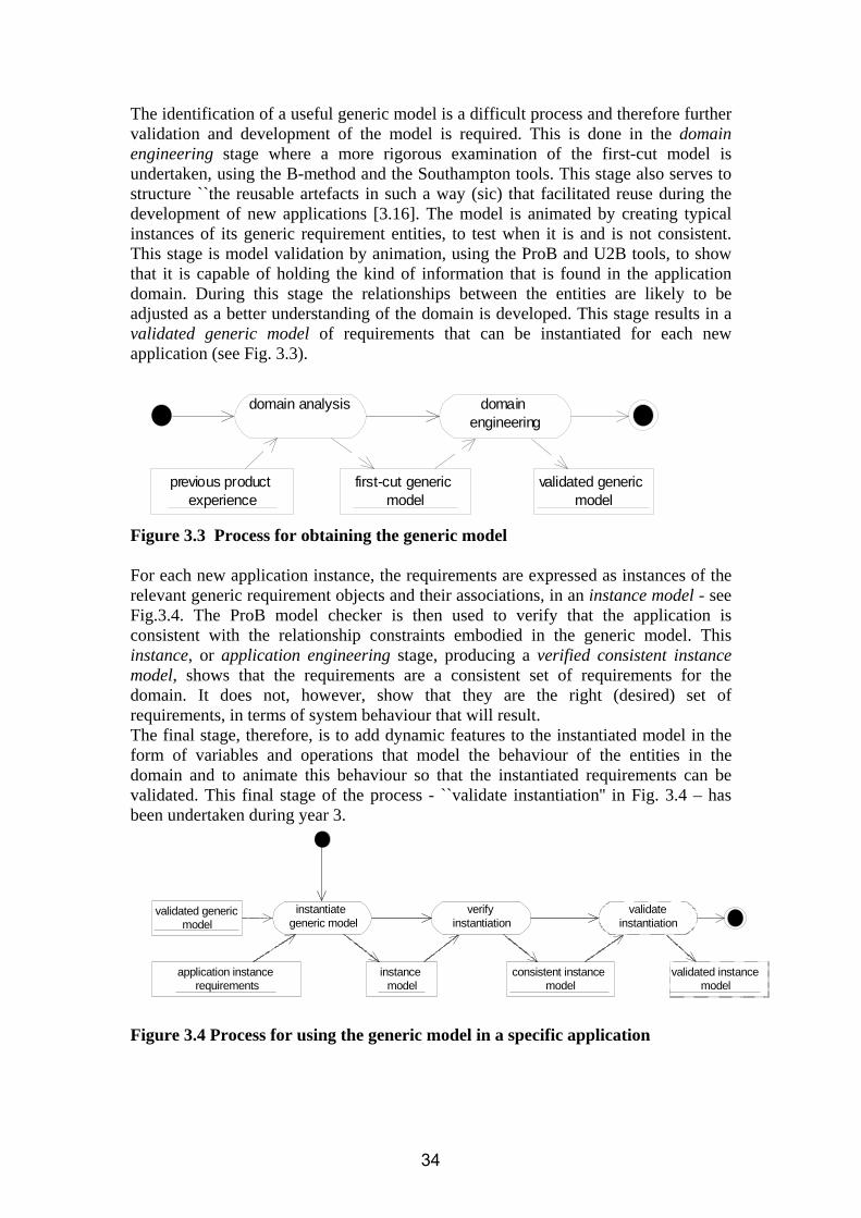
The identification of a useful generic model is a difficult process and therefore further validation and development of the model is required. This is done in the domain engineering stage where a more rigorous examination of the first-cut model is undertaken, using the B-method and the Southampton tools. This stage also serves to structure ``the reusable artefacts in such a way (sic) that facilitated reuse during the development of new applications [3.16]. The model is animated by creating typical instances of its generic requirement entities, to test when it is and is not consistent. This stage is model validation by animation, using the ProB and U2B tools, to show that it is capable of holding the kind of information that is found in the application domain. During this stage the relationships between the entities are likely to be adjusted as a better understanding of the domain is developed. This stage results in a validated generic model of requirements that can be instantiated for each new application (see Fig. 3.3).
domain analysis domain engineering
first-cut generic model
validated generic model
previous product experience
Figure 3.3 Process for obtaining the generic model For each new application instance, the requirements are expressed as instances of the relevant generic requirement objects and their associations, in an instance model - see Fig.3.4. The ProB model checker is then used to verify that the application is consistent with the relationship constraints embodied in the generic model. This instance, or application engineering stage, producing a verified consistent instance model, shows that the requirements are a consistent set of requirements for the domain. It does not, however, show that they are the right (desired) set of requirements, in terms of system behaviour that will result. The final stage, therefore, is to add dynamic features to the instantiated model in the form of variables and operations that model the behaviour of the entities in the domain and to animate this behaviour so that the instantiated requirements can be validated. This final stage of the process - ``validate instantiation'' in Fig. 3.4 – has been undertaken during year 3.
instantiate generic model
verify instantiation
validated generic model
application instance requirements
instance model
consistent instance model
validate instantiation
validated instance model
Figure 3.4 Process for using the generic model in a specific application
34

To address the problems found with using ProB to verify instantiation data, we developed a “Requirements Manager” tool that interfaces with the UML drawing tool to automate management and verification of instance configuration data [3.7]. The tool was developed as an IBM Eclipse plug-in by a student group, supporting the then prototype UML-B. The tool provides an extension to the Rational Software Architect UML modelling tool (also based on Eclipse). Menu extensions are provided to operate the tool from the class diagram so that a database repository can be generated based on the classes and their associations. Class instance and association link data can then be ‘bulk uploaded’ directly from the Excel configuration files containing the specific requirements data. This avoids the tedious and error prone process of manually populating the class diagram with this information. Further work was performed during year 3 to progress this work as a support plug-in for UML-B, to be called “Context Manager”. A substantial amount of tested code now exists for the import of instance system context data from Excel into a context database, its verification w.r.t. a context metamodel, and its formatting into a RODIN context file. However, this code is not yet functional and this work is ongoing. 3.1.3. Final year development of FMS and the PAT case 3.1.3.1 University of Southampton During the third year, work has advanced from a static model to a dynamic failure management system. The current model is a generic failure management system, which is re-usable and extensible. Re-usability is demonstrated by the integration of more specific contributions by Aabo Akademi. Further contributions that were made by Aabo Akademi (Aabo) and the University of Southampton can be summarised as:
1. Transfer of pilot study failure management system into Rodin Platform (Southampton)
2. Generic failure management system (Southampton) 3. Dynamic features of failure management system (Southampton, Aabo) 4. Development of failure management system using refinement (Southampton,
Aabo) 5. Translation of parts of Aabo’s classical B models into UML-B (Southampton) 6. Integration of Aabo and Southampton ideas (Southampton, Aabo)
In year 3, the focus of the development of FMS was on producing the dynamic part of the existing static model. The model was kept generic and abstract, such that it can later be refined into different more specific applications of FMS – thus enabling re-use. The tools helped to produce this generic model, which, when fully validated and verified, can serve as the basis of various detailed designs for various FMS manufacturers. As indicated in the introduction, the generic model can be seen as the composition of a number of functional features – detection, confirmation, condition and action – which can be adapted in further refinements. Furthermore, the year 2 FMS model was converted into the new UML-B, which was an effective way to develop the FMS model. UML-B is an extremely suitable tool for
35

the FMS model, due to the architectural concept of FMS. The model is mainly built on components with associations and object constraints, using an object-oriented development approach. During the process of model specification and refinement, a methodical approach emerged for developing models in the FMS domain with Rodin technology. These steps were
(1) development of configuration data model - the context model, (2) development of behavioural model, (3) if current model is a refinement of an abstract model, find gluing invariant, (4) validation of model (using the ProB animator plug-in), (5) validation classical B machine of model using ProB model checker (6) verification of model using the automatic and interactive prover.
These stages make up a Validation and Verification (V&V) methodology, which is explained in detail in the next section. This methodology is applied after every completed refinement stage, ensuring the correctness of the model. 3.1.3.2 Aabo Akademi (Aabo) In the final year of the FMS development we integrate the formal refinement approach to developing the FMS (previously proposed in [3.15] with a UML-based FMS development. We show how to develop the FMS generic models in UML-B, through a number of development phases supported by refinement-based model transformations. Development starts from an abstract FMS model expressed in UML-B. In general, we implement fault tolerance as an intrinsic part of the system by specifying its main steps: error detection and error recovery. The system structure and behaviour are specified using different types of UML-B diagrams, resulting in well-structured system specification. Each new development phase incorporates more details of the fault tolerance mechanisms into previous development phases, in a structured manner, while preserving already specified system properties and behaviour. Overview of the development. The development starts from an abstract FMS description, modelling the basic system functionality. This 1st development phase outlines the stages of the FMS operating cycle, starting with obtaining the sensor readings, processing them, and either failing or calculating the output of the FMS. In the latter case the FMS operating cycle starts again. In addition, the system safety properties are specified as safety invariants. They are preserved in the 2nd development phase, which introduces processing of inputs performed after obtaining the sensor readings. Namely, it introduces the error detection procedure within the FMS. The error detection classifies the inputs as faulty or fault-free, continuing the operating cycle as previously specified. In the 3rd FMS development phase, we abstractly introduce the input analysis performed by the FMS after the error detection. The result of the input analysis is the input statuses. They determine possible FMS recovery actions. At this phase, we also introduce a certain predefined stopping (freezing) condition, and express additional system safety properties. The 4th FMS development phase refines the input analysis. We define the input analysis as performed independently on each monitored sensor. In addition, we specify in detail the procedure of determining the input status based on using a specific counting mechanism. The 5th development phase refines already specified error detection mechanism by introducing the evaluation tests. They are applied on the obtained inputs, as defined by the given test architecture. The 6th FMS development phase further specifies the mechanism of the error detection. Namely, it introduces time
36

scheduling to enable test execution according to the given frequencies and the internal state of the system. Finally, the 7th development phase focuses on the details of the error detection mechanism by modelling different types of evaluation tests, while still preserving specified safety properties. The overall development results in UML-B diagrams representing general models, i.e., development templates, for developing similar systems. These templates can be instantiated for particular systems by populating the abstract data in templates by concrete data. For instance, we can consider different number of sensors, define concrete stopping conditions and internal system states, replace the abstract system configuration parameters (e.g., x, y, z etc.) with concrete values and so on. 3.1.3.3 ATEC The PAT Case In the final year ATEC has been required to be involved in work outside of the FMS case but has used this opportunity to try to adopt some RODIN related technology and still address the case study evaluation aims. The new case is outlined in the next section, and was presented at the Winchester workshop. The new case requires reusability, genericity and rigour appropriate to Rodin methods and could also provide an example of a generic application. In addition, the case had to utilise existing development which allows potential assessment of the technology to addressing legacy issues. This case contributes to the same metrics that were developed for the FMS case [3.3].
3.2. Major Directions on RODIN in Case Study Development This section describes the contribution of the case study in the final year. Evaluation is provided in D28 and D34 deliverables [3.10,3.8]. This section is organised as follows 3.2.1 FMS Case development University of Southampton 3.2.2 FMS Case development, Aabo Akademi 3.2.3 FMS Case development, ATEC 3.2.4 Impact on Methodological advances 3.2.5 Impact on platform and plugins 3.2.1. Development of the University of Southampton Generic FMS model 3.2.1.1 Abstract model: Feature class definition and semantic event sequencing The abstract model defines the object classes required to define the features of detection, confirmation, condition and action. The sequencing of key events remains nondeterministic, constrained only by the semantic requirements of the abstract model, i.e.
• all inputs for a given value updated before evaluation of the value, • all values for a detection updated before the detection is enabled • all detections for a confirmation performed before confirmation is enabled
37

The context of the abstract model was created first. The data and associations of the context model is described below. The data and context setup were taken in accordance to the original FMS specification [3.4].
Figure 3.5 – Context Diagram – Abstract Model The figure shows the context diagram of the abstract model. There are six class types, which have a set of instances.
• INP: The type of possible input signals that can be read by the FMS • VAL: The type of a value that an input is associated with. An input can have
one or more values, as recorded in association inpVal. • DET: Set of detections. Every value can have one or more detections, as
recorded in association detVal. • COND: Set of conditions on system state under which a detection is enabled.
If a condition is true for a certain detection, this detection is applied to check whether a value is erroneous or not. A condition is associated with one or more detections, as represented by detCond.
• CONF: This is the set of possible confirmations. A confirmation is mapped to one or more detections, as recored by the relation detConf.
• ACT: Set of possible actions. In this set we distinguish between healthy, confirming and confirmed actions. Every confirmation has one of each of those actions, recorded by ConfAct_H, ConfAct_C, ConfAct_P.
The class types and their relations (associations) constitute the static context setup.
38

This instantiation of the model (Fig. 3.5 - one example highlighted by red circle) was performed for validation purposes – which allow animating the model using the ProB animator plug-in. It is important to note that the distinction between abstract (generic) and concrete (specific instance configuration data definition) context specification is not made in RODIN at present. The distinction will be made and supported in future, in pursuit of full product-line working, by the Context Manager work discussed in the FMS précis in section 1 above. The behavioural model of the abstract stage is depicted below. It describes only semantic event sequencing between model objects, which is achieved by constraining the events using the relations between the classes. Otherwise there is no functionality at this level of abstraction; everything else in the model is abstract and non-deterministic. For example, pass or fail judgment of the detection feature is modelled as the indecisive pass_fail event here. Corresponding to the class types of the context model, there are six fixed classes; their instances are defined as the type expressions of the context. In this abstract model the relations between the classes are subsets of the corresponding context associations. The maplets in these relations represent the enabling of one object by another. For example, event evaluate for some VALUEx is only enabled once all maplets {INPy |-> VALUEx} for corresponding INPs { INPy} in context association inpVal, appear in variable association inpEnablesVal. Thus inpEnablesVal is a dynamic subset of static inpVal. As another example, dynamic detEnablesConf is a subset of static detConf. Enablement of a confirmation event for some CONFx requires all valid maplets {DETy |-> CONFx} to be retrieved from detConf and added to detEnablesConf. After that event is actioned, all these maplets are removed from detEnablesConf in order that the next detection/ confirmation cycle can run through for CONFx.
39
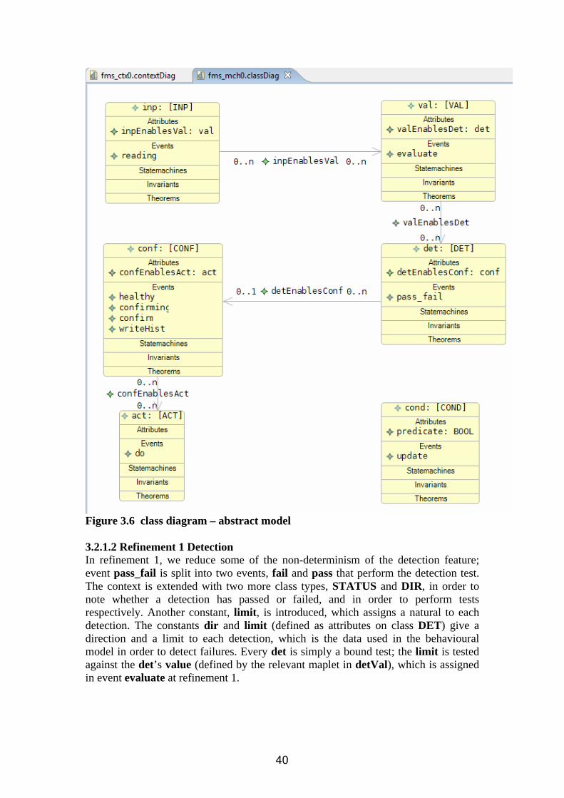
Figure 3.6 class diagram – abstract model 3.2.1.2 Refinement 1 Detection In refinement 1, we reduce some of the non-determinism of the detection feature; event pass_fail is split into two events, fail and pass that perform the detection test. The context is extended with two more class types, STATUS and DIR, in order to note whether a detection has passed or failed, and in order to perform tests respectively. Another constant, limit, is introduced, which assigns a natural to each detection. The constants dir and limit (defined as attributes on class DET) give a direction and a limit to each detection, which is the data used in the behavioural model in order to detect failures. Every det is simply a bound test; the limit is tested against the det’s value (defined by the relevant maplet in detVal), which is assigned in event evaluate at refinement 1.
40

Figure 3.7 context diagram – abstract model The behavioural model is refined to add more detail to the detection mechanism. In the abstract model, val was completely abstract and did not have a value. A value, as a natural-valued attribute on class VAL, is assigned here in order to perform the tests. This is still an abstract description; the computation of a val from its associated inps is a matter for lower-level refinement. The addition of those bound tests, i.e. test the value of a det against the limit and the direction against the direction set up in the context, reduces the non-determinism of pass_fail. Thus, the event pass_fail is refined into two separate events.
41

Figure 3.8 class diagram – refinement 1 The additions made to refinement 1 are highlighted in the figure above. The value attribute is added to class val, which is a function from val to a NAT, in order to give a number to each value. The event pass_fail has been refined into two separate events, which have all the detection mechanism added to their guards. The detState is set to either PASS or FAIL depending on the detection event that was enabled. Another very important issue of refinement is the verification of the refinement. This is done by introducing gluing invariants to the refinement. The gluing invariant used for this refinement states that as soon as a value is in the domain of valEnablesDet, that value is also in the domain of value, i.e. has a natural number assigned to it. 3.2.1.3 Refinement 2: Abstract confirmation via detection patterns The second refinement adds detail to the confirmation feature of the model. The class type CONF_STATE is introduced, whose instances are used to denote the state of confirmation. A confirmation is defined as a judgment at a point of time, at which the healthiness of a set of inputs is determined. The confirmation mechanism requires sets of patterns that are set up in the context. These patterns help determine, whether an
42

input is healthy, confirming or confirmed. In order to keep the model abstract and maintain the ability to refine it into different confirmation mechanisms/algorithms, the patterns are defined to be unique to each confirmation, i.e. each confirmation can have different patterns. There is a set of healthy patterns (healthy_pattern), and a set of confirmed patterns (conf_pattern). At this level of abstraction, this confirmation mechanism is already quite concrete, because it already defines a set of patterns of a certain length to help judge the healthiness of a set of inputs.
Figure 3.9: context diagram – refinement 2 The behavioural model is refined by adding a confirmation history (confHistory) recording mechanism, which records a sequence of BOOLs to denote passes and failures of each confirmation. The events healthy, confirming and confirm are also refined by adding guards to distinguish between healthy, confirming or confirmed patterns.
Figure 3.10: class diagram – refinement 2 New CONF attribute historyChanged denotes a change of history, i.e. TRUE is written to historyChanged when a new BOOL element is added to the sequence. The writeHist event is refined into two events in this refinement, to either write TRUE or FALSE to history. The guards of these two events distinguish which of the two events is enabled. Depending on the sequence of BOOLs, i.e. whether the sequence is a
43

subset of healthy patterns or confirmed patterns, either healthy or confirm is enabled respectively. Confirming is enabled in the case the sequence does not match either a healthy or a confirmed pattern. This confirmation mechanism is an abstract confirmation heuristic, which can be elaborated in further refinements. The confirmation heuristic is that if all dets of a conf have passed, TRUE is written to confHistory, whereas, if at least one det fails, FALSE is written to confHistory. The gluing invariant in this refinement shows the relation between confHistory and detState. It denotes that if the last element of a confHistory is FALSE, then at least one of the dets for this conf must have detState = FAIL. Similarly, if the last element of confHistory is TRUE, the detStates for all associated dets must be PASS. 3.2.1.4 Refinement 3: Aabo integration – process cycle statemachine In this refinement, integration of part of the Aabo model into the Southampton model is shown. The Aabo model consists of a system statemachine, constraining the sequence of events in a linear manner typical of the target processor cycle. This sequence allows all inputs to be read first, which then has to be followed by the evaluation, then the detection, the confirmation loop and then an action. In order to incorporate this into the model, a statemachine is introduced, which defines this sequence of events.
44

Figure 3.11: statemachine and class diagram – refinement 3 Figure 3.11 shows the statemachine that was added to the model. The statemachine has five states. These states are added to all the events in the class diagram (not shown in figure) to restrict the events, i.e. guard added to reading event – fmsState = fms_env, which only enables the event reading when the system is in state fms_env. When all inputs have been read, the event allRead is enabled, which will set the system state to fms_val, which enables the evaluate event. Thus event guard strengthening reduces the non-determinism in event sequencing. In this way, Aabo’s FMS state idea was successfully integrated into the Southampton model. 3.2.1.5 Refinement 4: Aabo integration: concrete confirmation via counting algorithm In refinement 4, Aabo’s counting algorithm (precisely that of the original CS2 specification [3.4] is integrated into the model. The context diagram had to be extended to include the different constants required by Aabo’s counting algorithm. In the current model these constants are global, i.e. not unique to each conf.
45

These are • ZZ : counter limit • LIMIT: maximum number of cycles allowed before a confirmation fails • XX: added to the counter if there is a fail • YY: subtracted from the counter if there is a pass. In summary, the counting algorithm keeps a counter for each confirmation. This counter is set to two, and whenever there is a failed detection, XX is added to the counter. Should the detection pass, YY is subtracted from the counter. Once the counter reaches zero, the input is considered healthy, and if a set counter limit ZZ is reached, the input is considered failed. There is a restriction on the maximum number of cycles allowed (LIMIT); for each cycle, another counter, which is unique to each confirmation, is incremented by one. If LIMIT is reached, the input is also considered failed.
Figure 3.12: context diagram – refinement 4 Due to some UML-B restrictions (see feature request 1777268) the existing events healthy, confirming, confirmed, had to be fully moved into the statemachine in order to be able to use a statemachine for refinement. The additional data that was added to the guards required some of the events to be refined into two events.
46
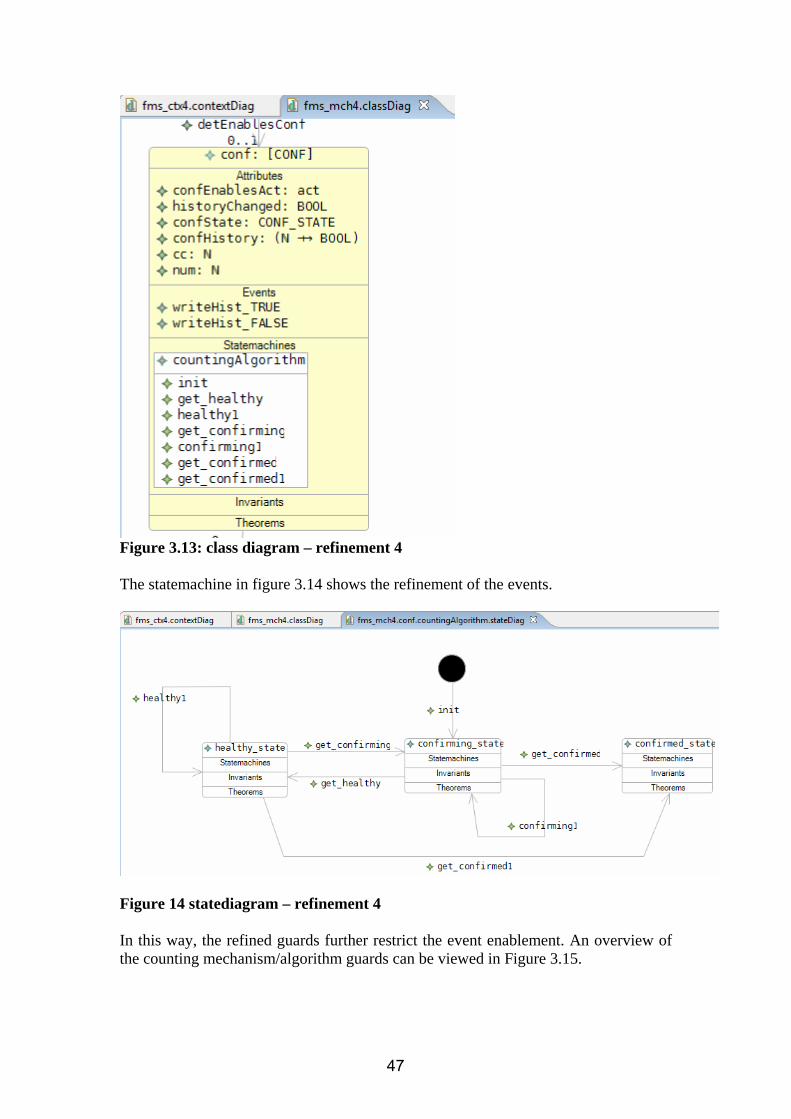
Figure 3.13: class diagram – refinement 4 The statemachine in figure 3.14 shows the refinement of the events.
Figure 14 statediagram – refinement 4 In this way, the refined guards further restrict the event enablement. An overview of the counting mechanism/algorithm guards can be viewed in Figure 3.15.
47

Figure 3.15: Integration of counting algorithm This chart shows the original event names, which, for modelling reasons had to be renamed in the Rodin platform. Blue denotes the history mechanism of the Southampton model, whereas red denotes the guards of Aabo’s counting algorithm. 3.2.2. FMS Case Development (Aabo) The UML-B development of the FMS is performed in phases. Each development phase is described by a set of UML-B models depicting the main structural and behavioural aspects of the FMS at a corresponding level of abstraction.
Phase 1: Abstract specification of the FMS
In the 1st development phase we model the FMS cycle very abstractly: the FMS reads input values from the sensors, and it either calculates the output or fails. If the output is successfully calculated, the FMS cycle starts again. In case of a failure, the system enters the ‘freezing’ state.
48

env
actout
freeze
Environm ent / def_Set_InputN
Action / def_Update
Action
Return / def_Set_Output
Fail
<<machine>> FMS0 FMS
Output : NAT
Environment()Action()Return()Fail()<<s tatic>> def_Set_Output()
INDEXInputN : NATLast_Good_InputN : NAT
<<static>> def_Set_InputN()<<s tatic>> def_Update()
ACCEPTABLE_INPUTS
GOOD_INPUTS
Figure 3.16. The class diagram and the statechart fms_state for the 1st FMS development phase Structure. The abstract FMS is modelled as the stereotyped package <<machine>> FMS0. The corresponding class diagram outlines the general system structure. The class FMS models the generic part of the system, i.e., properties of the whole system. For instance, the calculated system output is modelled as the attribute Output of the class FMS. The concrete sensor readings, i.e., input values to the FMS are modelled as the attribute InputN of the class INDEX that models the monitored sensors. To model the procedure of calculating the FMS output, we introduce the attribute Last_Good_InputN to the class INDEX. Moreover, INDEX becomes a superclass of the subclass ACCEPTABLE_INPUTS, which models the inputs from sensors that did not fail. Similarly, the subclass GOOD_INPUTS further partitions the space of ACCEPTABLE_INPUTS by modelling the fault-free inputs only. Behaviour. The class FMS encapsulates the overall system behaviour within the attached fms_state statechart. The names of the states within this statechart correspond to the phases of the FMS operating cycle. They have the following meaning: env – the state in which the FMS obtains inputs from the monitored sensors, act – the state in which the FMS analyses the inputs and performs recovery actions, if needed, out – the state in which the FMS calculates and sends the output to the controller, freeze – the state in which the FMS freezes (i.e., shuts down the system). The transitions between states are directly related with the methods defined in the class FMS. After the FMS is initialized, the FMS operating cycle starts by executing the method Environment. It triggers the action def_Set_InputN, specified on the corresponding transition in the statechart fms_state. The action simulates the inputs readings by arbitrarily setting the values of the attribute InputN for all instances of the INDEX class. After that, the FMS executes the method Action, i.e., it either fails or continues by calculating the output. In case the FMS has successfully calculated the output, the action def_Update updates the set of the monitored sensors, considering in further FMS cycles only those which did not fail. The acceptable inputs are arbitrarily chosen from the set of inputs of all operational (non-failed) sensors. If the FMS has not failed at the current cycle, it produces the system output by executing the method Return, which corresponds to the statechart transition with the same name. The output is calculated based on the last good input values, which are systematically updated by the values of the fault-free inputs at each FMS cycle. If the FMS fails, it does not resume its cyclic behaviour and stays in the failed (i.e., frozen) state. To ensure
49

system safety, we define an invariant attached to the FMS class. This safety invariant specifies that the FMS can operate relying only on the sensors that have not failed.
Phase 2: Introducing error detection by refinement
The 2nd FMS development phase introduces an abstract representation of error detection, performed by the FMS after obtaining the sensor readings. Hence, we enhance the specification of the FMS cycle to include the error detection mechanism. Namely, after reading the input values from the monitored sensors, the FMS performs the predefined error detection procedure on them. As a result, it classifies the inputs as faulty or fault-free. Then, it continues its operation as specified in the previous development phase.
<<refinement>> FMSR1 FMS
Output : NAT
Environm ent()Detection()Action()Return()Fail()<<static>> def_Set_Output()
INDEXInputN : NATLas t_Good_InputN : NATInput_In_ErrorN : BOOL
<<s tatic>> def_Set_InputN()<<s tatic>> def_Update()<<s tatic>> def_Reinitialize()<<s tatic>> def_Set_Input_In_ErrorN()
GOOD_INPUTS
ACCEPTABLE_INPUTS
env
out
Return / def_Set_Output || def_Reinitialize
freeze
Fail
act
det
act1
det
Environm ent / def_Set_InputN
act1
Action / def_Update
Action
Detection / def_Set_Input_In_ErrorN
Figure 3.17. The class diagram and the statechart fms_state for the 2nd FMS development phase
Structure. The class diagram of the package FMSR1 preserves the structure defined at the previous development phase. However, to model the results of the error detection, we introduce the new attribute Input_In_ErrorN into the class INDEX. It is a boolean attribute, which is set to TRUE if the error is detected on the monitored input, and to FALSE otherwise. Initially, we consider that the inputs are fault-free. Behaviour. To incorporate an abstract model of error detection, we refine the statechart by adding the new substates det and act1 within the existing state act, and the corresponding new transition Detection between them. However, we preserve the flat statechart representation. The action def_Set_Input_In_ErrorN defined in the method Detection nondeterministically assigns values to the variable Input_In_ErrorN. Since at each FMS cycle all the inputs are initially considered fault-free, the attribute Input_In_ErrorN has to be reinitialized. Therefore, we introduce the method def_Reinitialize into the class INDEX. The method sets the values of Input_In_ErrorN to FALSE, meaning that none of the monitored inputs is considered faulty before actual detection is performed.
Phase 3: Introducing input analysis by refinement
In the 3rd FMS development phase we introduce an abstract representation of input analysis performed by the FMS after the error detection. Once the FMS detects a faulty input, it uses the input analysis to decide whether it can be recovered or not. Then it saves the results of the analysis as the current input status and continues its
50

operation either by calculating the output or failing when a certain predefined stopping condition is satisfied.
<<refinement>> FMSR2 FMS
Output : NAT<<constant>> StopCond : BOOL
Environm ent()Detection()Analys is ()Action()Return()Fail()<<static>> def_Set_Output()
INDEXInputN : NATLast_Good_InputN : NATInput_In_ErrorN : BOOLInput_StatusN : INPUT_STATUSN
<<static>> def_Set_InputN()<<static>> def_Update()<<static>> def_Reinitialize()<<static>> def_Set_Input_In_ErrorN()<<static>> def_Set_Input_StatusN()
GOOD_INPUTS
ACCEPTABLE_INPUTS
env
out
Return / def_Set_Output || def_Reinitialize
freeze
Fail
det
Environm ent / def_Set_InputN
act1
anl
act2
anl
Detection / def_Set_Input_In_ErrorN
act2
Analys is / def_Set_Input_StatusN
Action[ not(StopCond) ] / def_Update
Action[ StopCond ]
Figure 3.18. The class diagram and the statechart fms_state for the 3rd FMS
development phase Structure. To introduce the details of the input analysis, we first modify the structure of our model by altering the class diagram of the package FMSR2. To model the obtained result of the input analysis, we add the attribute Input_StatusN to the class INDEX. Possible values of this attribute are either ok (represents a fault-free input), suspected (represents a faulty yet recoverable input), or confirmed_failed (represents a faulty but non-recoverable input). We also introduce an abstract representation of the stopping condition as a boolean attribute StopCond in the class FMS. If StopCond is evaluated to TRUE, the system should be stopped (i.e., shut down). Behaviour. To specify the input analysis in the FMS operating cycle, we refine the state act1 in the statechart fms_state. We add the new substates anl and act2 to the state act1 and the transition Analysis between them. Its action part, explicitly describing the input analysis calculations, is defined as the method def_Set_Input_StatusN of the class INDEX. The method produces a result of the input analysis on the basis of the error detection results from the previous step. Namely, the inputs detected as faulty become either suspected or confirmed_failed, whereas the inputs detected as fault-free are given the status of either ok or suspected. The abstract subclasses ACCEPTABLE_INPUTS and GOOD_INPUTS are refined using the information about the input status. We define the acceptable inputs as the inputs whose status is ok or suspected. Similarly, the good inputs are the inputs whose status is ok. Phase 4: Refining the input analysis
The 4th FMS development phase further refines the input analysis. In the previous phase, we defined the input analysis as an atomic action, which assigns the statuses of all monitored sensors at once, where in reality the sensor inputs are analyzed independently, i.e., one by one, until all the inputs are analyzed (processed). In this phase, we also specify in detail the procedure of determining the input status. It is based on using a specific counting mechanism, which re-evaluates the status of the analyzed inputs at each FMS cycle, allowing us to introduce input recovery. As a result, some of the suspected inputs can be recovered and used in the next FMS cycle.
51

env
det
anl
anlloop
fin_anl
act2freeze
Action[ StopCond ]
Fail
out
Action[ not(StopCond) ] / def_Update
Return / def_Set_Output || def_Reinitialize Environm ent / def_Set_InputN
anlloop
Detection / def_Set_Input_In_ErrorN
Analys isLoop[ ran(Processed)/={TRUE} ] / def_Set_Input_StatusN1
fin_anl
Analys isLoop[ ran(Processed={TRUE}) ]
Analys is / def_Set_Input_StatusN
<<refinement>> FMSR3
FMSOutput : NAT<<constant>> StopCond : BOOL<<constant>> x : NAT<<constant>> y : NAT<<constant>> z : NAT<<constant>> Lim it : NAT
Environm ent()Detection()Analys isLoop()Analys is ()Action()Return()Fail()<<static>> def_Set_Output()
INDEXInputN : NATLast_Good_InputN : NATInput_In_ErrorN : BOOLInput_StatusN : INPUT_STATUSNProcessed : BOOLcc : NATnum : NAT
<<static>> def_Set_InputN()<<static>> def_Update()<<static>> def_Reinitialize()<<static>> def_Set_Input_In_ErrorN()<<static>> def_Set_Input_StatusN()def_Set_Input_StatusN1()
ACCEPTABLE_INPUTS
GOOD_INPUTS
Figure 3.19 The class diagram and the statechart fms_state for the 4th FMS development phase
Structure. To model realistic input analysis and a counting mechanism (i.e., recovery) required for the input analysis, we extend the class diagram with additional attributes. First, we focus on the data structures needed to model the step-by-step input analysis. Since the analysis is performed on each input (i.e., each instance of the class INDEX), we need to keep the record of those inputs that are already analysed within the current operating cycle. Hence, in the class INDEX we introduce the boolean attribute Processed. It is set to TRUE, if the input has been processed, and to FALSE otherwise. The attributes introduced to support the counting mechanism should enable controlled input recovery. To ensure error recovery termination, we need a counter that keeps track of input behaviour. Hence, we introduce the attribute cc into the class INDEX. It accumulates the values determining how trustworthy a particular input is. If the input is determined as faulty, its trustworthiness is “measured” by a certain predefined value x, generic for the system and hence introduced as a constant attribute in the class FMS. On the other hand, if the input is determined as fault-free, its trustworthiness is evaluated by another predefined value y, introduced similarly as the attribute x. To ensure finite error recovery, we should keep cc below the predefined upper limit z, which is introduced as an additional configuration parameter. Moreover, we introduce an additional counter num, which counts the number of the consequent recovery cycles for each recovering input. In addition, we specify the maximum number of the allowed recovery cycles for all inputs as the constant attribute Limit of the class FMS. Both num and Limit are specific for the whole system and hence are defined as attributes of the class FMS. Behaviour. To model the input analysis, we need to extend the FMS state space by adding a new hierarchical state to the existing statechart fms_state. Specifically, we refine the state anl by unfolding its substates anlloop and fin_anl. A new transition between these substates specifies an additional FMS method – AnalysisLoop. In general, after performing the error detection, the FMS starts analyzing the inputs one by one, until all the inputs are processed. Hence, the guard ran(Processed)={TRUE} of the transition AnalysisLoop defines the terminating condition for the analysis. The FMS implements the gradual input analysis as specified by a newly introduced statechart
52

attached to the class INDEX – Input_StatusN1. It describes a deterministic procedure of determining the status of a single input.
ok
suspected
confirmed_failed
def_Set_Input_StatusN1[ Input_In_ErrorN=FALSE & G3 ] / A3
def_Set_Input_StatusN1[ Input_In_ErrorN=FALSE & G3 ] / A3
def_Set_Input_StatusN1[ Input_In_ErrorN=FALSE & G3 ] / A3
def_Set_Input_StatusN1[ Input_In_ErrorN=TRUE & G1 ] / A2
def_Set_Input_StatusN1[ Input_In_ErrorN=TRUE & G1 ] / A2
def_Set_Input_StatusN1[ Input_In_ErrorN=FALSE & G2 ] / A1
def_Set_Input_StatusN1[ Input_In_ErrorN=FALSE & G5 ]
where:
G1=(num+1 ≥ Limit OR cc+x ≥ z) G2=(num+1<Limit ∧ cc-y=0) G3=(num+1<Limit ∧ cc-y>0) G4=(num+1<Limit ∧ cc+x<z) G5=(num=0 ∧ cc=0)
A1=(num:=0 ∥ cc:=cc-y) A2=(num:=num+1 ∥ cc:=cc+x) A3=(num:=num+1 ∥ cc:=cc-y)
Figure 3.20. The statechart Input_StatusN1 specifying the behaviour of the class
INDEX The input status changes depending on the values of the configuration parameters x, y, z, cc, Limit, and num. For clarity, in the statechart we use the abbreviations to express the guards and the corresponding actions specifying the transition def_Set_Input_StatusN1. It corresponds to the method of the class INDEX and operates on the instances of this class (i.e., on single inputs), rather then on the whole class. In our previous development phases, we defined the attribute Input_StatusN modelling the results of the input analysis performed within the method def_Set_Input_StatusN. Now, the statechart Input_StatusN1 describes the change of the input status for a single input. To establish the refinement relationship between the old attribute Input_StatusN and the newly introduced statechart Input_StatusN1, we refine the method Analysis from the previous development phase. Namely, after all inputs are analyzed (i.e., AnalysisLoop is completed), the intermediate results of the analysis are assigned to the attribute Input_StatusN. Since each new FMS operating cycle should start with unprocessed inputs, the attribute Processed should be reinitialized. The action def_Reinitialize is refined to implement this requirement.
Phase 5: Refining the error detection – introducing the evaluation tests
In the 2nd development phase, we already abstractly specified the error detection part of the FMS. In this development phase, we further refine it by introducing the evaluation tests that are consecutively applied on the obtained inputs. They determine the result of the detection for each input separately, rather than for all of them at once, as modelled in the previous phases. After executing all predefined tests on the obtained inputs, the FMS proceeds with the input analysis based on the results of the applied tests, as described earlier.
53

Structure. To model evaluation tests, we introduce an additional class into our previous class diagram – the class TEST. The tests applied to the inputs obtained by the FMS form a specific architecture expressing the dependencies between them. These dependencies are modelled as the association
T
ComplexTest. This allows us to distinguish between tests that are independent and those that depend on the results of other tests. The additional constraint attached to the association ComplexTest requires that a test can not depend on itself.
<<refinement>> FMSR4FMS
Output : NAT<<cons tant>> StopCond : BOOL<<cons tant>> x : NAT<<cons tant>> y : NAT<<cons tant>> z : NAT<<cons tant>> Limit : NAT
Environm ent()DetectionLoop()Detection()Analys isLoop()Analys is ()Action()Return()Fail()<<static>> def_Set_Output()
ACCEPTABLE_INPUTS
GOOD_INPUTS
ITTestExecuted : BOOLTestPassed : BOOL<<static>> Counter : NAT
<<static>> def_Set_Counter()def_RunTestOnInput()
INDEXInputN : NATLas t_Good_InputN : NATInput_In_ErrorN : BOOLInput_StatusN : INPUT_STATUSNProcessed : BOOLcc : NATnum : NATInput_In_ErrorN1 : BOOL
<<s tatic>> def_Set_InputN()<<s tatic>> def_Update()<<s tatic>> def_Reinitialize()<<s tatic>> def_Set_Input_In_ErrorN()<<s tatic>> def_Set_Input_StatusN()def_Set_Input_StatusN1()def_Set_Input_In_ErrorN1()
TEST
1..n0..n
1..n
ComplexTest
<<cons tant>>
{!aa.(aa:dom(ComplexTest)=>aa/:ComplexTest(aa))}
0..n
env
anlloop
Analys isLoop[ ran(Processed)/={TRUE} ] / def_Set_Input_StatusN1
fin_anl
Analys isLoop[ ran(Processed)={TRUE} ]
act2
Analys is / def_Set_Input_StatusN
freeze
Action[ StopCond
Figure 3.21. The class diagram and the statechart fms_state for the 5th FMS development phase
We need to keep track of all tested inputs and their test results. Hence, we introduce the association class IT, modelling the set of all (test, index) pairs in the following way. If it is an instance of IT, then it.test refers to its first element, and it.index to the second element. For each such instance, we first define whether the particular input has been tested by its corresponding test. We model this by introducing the boolean attribute TestExecuted into the class IT. For each instance the attribute either has the value TRUE, if it.index has been tested by it.test, or FALSE otherwise. Similarly, the boolean attribute TestPassed models the results of test execution for instances of IT. The attribute has the value TRUE, if the test has been successfully passed by the corresponding input, and FALSE otherwise.
]
out
Action[ not(StopCond) ] / def_Update
Return / def_Set_Output || def_Reinitialize
det
detloop
fin_det
detloop
Environm ent / def_Set_InputN || def_Set_Counter
DetectionLoop[ Counter>0 ] / def_RunTestOnInput ; def_Set_Counter
fin_det
DetectionLoop[ Counter=0 ]
Detection / def_Set_Input_In_ErrorN
54

Since the decision whether some particular input is faulty may be based on more than single test execution, in the class INDEX we introduce the attribute Input_In_ErrorN1, which represents the final result of the error detection based on all tests executed on that input. In addition, to model the terminating condition for the error detection, we introduce the static attribute Counter in the class IT. This attribute defines the number of the remaining tests still to be executed on the inputs from the monitored sensors. Behaviour. Refinement of the error detection introduces the substates detloop and fin_det within the state det. The transition DetectionLoop between these substates is specified as an additional FMS method. In general, after obtaining the inputs from the monitored sensors, the FMS proceeds with error detection on single inputs, until all the inputs are determined faulty or fault-free, i.e., until all the tests required to be executed on each input are applied. Hence, the guard Counter=0 of the transition DetectionLoop defines when the detection process is completed. The value of the Counter is set prior to the error detection by the action def_ Set_Counter within the method Environment. In addition, Counter is re-evaluated after each detection loop by the same action. This action sets Counter to the number of IT instances that have not been tested yet. After determining the initial number of DetectionLoop iterations, the FMS implements step-by-step error detection, as specified by a newly introduced statechart attached to the class IT – TestOnInput. Initially, none of the tests is executed. The method def_RunTestOnInput of the class IT specifies the detection in detail. It is associated with the transitions of the statechart TestOnInput. The method results in distinguishing between faulty and fault-free inputs. Namely, when an input has successfully passed a certain test (TestPassed=TRUE), the value of Input_In_ErrorN1 stays unchanged, i.e., it remains FALSE as specified initially. However, if the test has failed (TestPassed=FALSE), the value of Input_In_ErrorN1 for the tested input is set to TRUE by the corresponding action def_Set_Input_In_ErrorN1.
not_executed
executed_undefined
def_RunTestOnInput / Tes tPassed::BOOL || TestExecuted:=TRUE
executed_passed executed_not_passed
def_RunTestOnInput[ Tes tPassed=TRUE ] def_RunTestOnInput[ TestPassed=FALSE ] / def_Set_Input_In_ErrorN1(self.index)
Figure 3.22. The statechart diagram TestOnInput
This refinement step focuses on refining the method Detection. In the previous models, its action def_Set_Input_In_ErrorN nondeterministically set the error detection results at once, on all obtained inputs. Now, however, these results are determined consecutively, for each single input and then after accumulated in Input_In_ErrorN1 assigned to Input_In_ErrorN. The safety invariant of this development phase guarantees that, if any of the tests applied on a certain input has failed, the input is considered in error. Moreover,
55

we require that, for some input to be fault-free, it should successfully pass all the executed tests.
Phase 6: Refining the error detection – introducing the time scheduling
The 6th FMS development phase further specifies the mechanism of the error detection. The applicability of the evaluation tests, introduced in the previous development phase, depends on the test frequencies and the internal state of the system. At this development phase, we introduce this information into the error detection procedure. Namely, to enable tests executions according to the given frequencies, we introduce time scheduling. We model a global clock, which is used to guarantee that the tests with the same frequencies are executed at the same time instances. Structure. The main structural change in the 6th development phase is the introduction of two additional classes into the system. The first one – the class STATES – allows us to model the set of internal states of the system. The second one – the class CONDITION – is an association class. It has only one boolean attribute Cond, modelling the enableness of a certain test with respect to the internal system state. If Cond is TRUE then the corresponding test is enabled for execution at the given internal system state. Otherwise, it is disabled. By introducing the attributes Time and State into the class FMS, we actually implement the concepts of the current time and the current internal system state. Since the enableness of an evaluation test depends not only on the internal system state but also on the given test frequency, we add the attribute Freq to the class TEST. It models the predefined execution frequency for each test. Furthermore, we explicitly define how and when the time progresses in our system. Hence, we introduce the attribute Clock_Flag into the class FMS, modelling the state of the time scheduler. It can be either enabled or disabled. Initially, we assume it to be disabled.
<<refinement>> FMSR5
ACCEPTABLE_INPUTS
GOOD_INPUTS
ITTestExecuted : BOOLTestPassed : BOOL<<static>> Counter : NAT
<<static>> def_Set_Counter()def_RunTestOnInput()
CONDITION<<cons tant>> Cond : BOOL
FMSOutput : NAT<<cons tant>> StopCond : BOOL<<cons tant>> x : NAT<<cons tant>> y : NAT<<cons tant>> z : NAT<<cons tant>> Lim it : NATTim e : NATURALState : STATESClock_Flag : CLOCK_STATES
Environm ent()DetectionLoop()Detection()Analys isLoop()Analys is ()Action()Return()Fail()<<s tatic>> def_Set_Output()TickTime()
INDEXInputN : NATLast_Good_InputN : NATInput_In_ErrorN : BOOLInput_StatusN : INPUT_STATUSNProcessed : BOOLcc : NATnum : NATInput_In_ErrorN1 : BOOL
<<static>> def_Set_InputN()<<static>> def_Update()<<static>> def_Reinitialize()<<static>> def_Set_Input_In_ErrorN()<<static>> def_Set_Input_StatusN()def_Set_Input_StatusN1()def_Set_Input_In_ErrorN1()
STATES
TEST<<cons tant>> Freq : NAT
1..n
0..n
1..n
ComplexTest
<<constant>>
{!aa.(aa:dom(ComplexTest)=>aa/:ComplexTest(aa))}
0..n
Figure 3.23. The class diagram for the 6th FMS development phase
Behaviour. To model time scheduling of tests depending on their frequencies and the internal system state, we need to specify how the time in the system changes and how it affects the evaluation tests. This is defined by the method TickTime in the class FMS. The method increments the value of the current time, whenever Clock_Flag is enabled
56

and there exist the tests enabled for execution at the current time instance. In addition, it models a possible change of the internal system state by nondeterministically updating the attribute State. When there are no more tests enabled for execution, Clock_Flag is disabled and the FMS cycle proceeds as specified earlier. A new FMS cycle can start only after the previous one finishes, i.e., the time should not progress before the cycle is finished. Hence, we add the guard Clock_Flag=disabled on the transition Environment in the diagram fms_state. The main focus of this refinement step is on refining the method def_RunTestOnInput by introducing additional guards to the corresponding transitions in the statechart TestOnInput. These guards specify that: the tests are executed with certain given frequencies; for some complex test to be executed, its frequency has to be divisible by the frequencies of all the simple tests required for its execution; execution of each test depends on the current internal state of the system.
Phase 7: Refining the error detection – introducing types of evaluation tests
The 7th development phase continues to elaborate on the error detection mechanism by modelling different types of evaluation tests. We replace the nondeterministic detection procedure by a deterministic one, which introduces concrete steps of test application. Structure. To introduce specific types of the evaluation tests, we define the subclasses of the class TEST. The subclasses are: MAG – the magnitude tests, PRED – the predicted value tests, RATE – the rate tests, MULT – the dual sensor difference tests. Each of the subclasses also introduces test specific properties, by defining them as subclass attributes. For instance, the subclass MAG has two constant attributes upLimit (the upper limit of an input) and loLimit (the lower limit of an input) needed for the execution of the magnitude test.
<<refinement>> FMSR6
FMSOutput : NAT<<cons tant>> StopCond : BOOL<<cons tant>> x : NAT<<cons tant>> y : NAT<<cons tant>> z : NAT<<cons tant>> Lim it : NATTim e : NATURALState : STATESClock_Flag : CLOCK_STATES
Environm ent()DetectionLoop()Detection()Analys isLoop()Analys is()Action()Return()Fail()<<s tatic>> def_Set_Output()TickTime()
ACCEPTABLE_INPUTS
GOOD_INPUTS
ITTestExecuted : BOOLTestPassed : BOOL<<static>> Counter : NAT
<<static>> def_Set_Counter()def_RunTestOnInput()<<s tatic>> def_Testing()
CONDITION<<cons tant>> Cond : BOOL
STATESINDEX
InputN : NATLast_Good_InputN : NATInput_In_ErrorN : BOOLInput_StatusN : INPUT_STATUSNProcessed : BOOLcc : NATnum : NATInput_In_ErrorN1 : BOOLPrevious_InputN : NAT
<<static>> def_Set_InputN()<<s tatic>> def_Update()<<s tatic>> def_Reinitialize()<<s tatic>> def_Set_Input_In_ErrorN()<<s tatic>> def_Set_Input_StatusN()def_Set_Input_StatusN1()def_Set_Input_In_ErrorN1()
TEST<<cons tant>> Freq : NAT
1..n
0..n
1..n ComplexTest
<<cons tant>>
{!aa.(aa:dom(ComplexTest)=>aa/:ComplexTest(aa))}
0..n
MAG<<constant>> upLimit : NATURAL<<cons tant>> loLim it : NATURAL
PRED<<cons tant>> Tolerance : NATURAL<<cons tant>> Predicted_Value : NATURAL-->NATURAL
RATE<<cons tant>> rateLimit : NATURAL
MULT<<constant>> diffLim it : NATURAL
Figure 3.24. The class diagram for the 7th FMS development phase
57
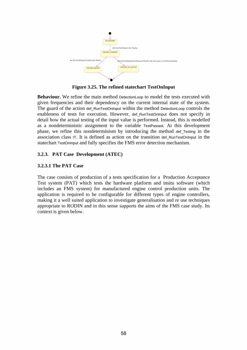
executed_undefined
not_executed
def_RunTes tOnInput / def_Tes ting
executed_passed executed_not_passed
def_RunTes tOnInput[ Tes tPassed=TRUE ] def_RunTestOnInput[ Tes tPassed=FALSE ] / def_Set_Input_In_ErrorN1(self.index)
Figure 3.25. The refined statechart TestOnInput
Behaviour. We refine the main method DetectionLoop to model the tests executed with given frequencies and their dependency on the current internal state of the system. The guard of the action def_RunTestOnInput within the method DetectionLoop controls the enableness of tests for execution. However, def_RunTestOnInput does not specify in detail how the actual testing of the input value is performed. Instead, this is modelled as a nondeterministic assignment to the variable TestPassed. At this development phase, we refine this nondeterminism by introducing the method def_Testing in the association class IT. It is defined as action on the transition def_RunTestOnInput in the statechart TestOnInput and fully specifies the FMS error detection mechanism. 3.2.3. PAT Case Development (ATEC)
3.2.3.1 The PAT Case The case consists of production of a tests specification for a Production Acceptance Test system (PAT) which tests the hardware platform and insitu software (which includes an FMS system) for manufactured engine control production units. The application is required to be configurable for different types of engine controllers, making it a well suited application to investigate generalisation and re use techniques appropriate to RODIN and in this sense supports the aims of the FMS case study. Its context is given below.
58

TEST SPECIFICATION BUILDE
R
TEST OPERATOR
TEST INSTANCE
PAT TEST PLATFORM
TEST RIG
Production Unit under test
TEST CERTIFICATE
Figure 3.26 – PAT Context Diagram Basic Functionality
• The test specification builder provides a series of tests (test instances)to be applied to a production unit on a test rig. Variants of the test specification are required for different types of production units.
• Some tests inform a test operator to set the test environment to particular
settings and make some observations. Some tests are transparent to the operator.
• On completion a test certificate is produced for a given production unit which
provides evidence to the customer of the acceptance test status
59

3.2.3.2 Development The functional requirements for the PAT system were derived principally from a customers new manual test requirement but to work in conjunction with an existing semi automatic test facility. It was desirable that the design would have to be flexible to change as future changes in the test requirement would likely occur. Initial development began with investigation into the modification/reuse of an existing test system. However it soon became apparent that the existing design was very specialised to individual test instances making modification for reuse difficult, this together with the need for flexiblity in the design encouraged a more generic approach. This need for a more generic solution served several purposes
1. Catered for instantiation of new test instances for other variants of units 2 Ease development of new test behaviour 3 Reduced the Validation time of the test system as fewer system components requiring verification
The development would need to meet commercial timescales and would have to integrate with existing test facilities. Adopting Rodin technology The generic requirement of the PAT system is suited to the Rodin task aims of genericity. However, achieving complete behavioural modelling of a system in order to produce a direct implementation was not seen viable for several reasons
1. ATEC has limited modelling experience and no real experience in producing implementation code from such a model. The dual code model of year two illustrated only simple translation.
2. The commercial timescale meant there was too much risk in attempting this development and failing.
3. The use of some legacy code was desirable where specification did not exist and integration into existing test facilities was desired.
4. The use of a legacy compiler (Borland c) was required in order to integrate with existing code.
The approach taken was to consider a development which would encapsulate some Rodin methods to assist generic design and provide some rigour to development. The architectural design was split into a generic configuration part which has been subject to Rodin related technology and a target implementation which has been developed along more traditional lines but influenced by the generic system.(The intention being to perform behavioural modelling of the target behaviour later using the Rodin tools.) The generic configuration could be developed from a structural domain model appropriate to the methods already developed in the FMS case study. Operationally it provides an editor where the test requirement can be constructed by selecting test items specified in the domain model to form a test specification. This specification is then built into a file of commands which the target system interprets into executable test actions. The architecture is illustrated in the fig 3.27 below. It illustrates the PAT structural model generating a customised PAT editor by using EMF technology running on the Eclipse platform. The editor is used to enter the test instance
60

requirement in a structured way. This is then converted to a formatted text file by a developed builder. The formatted text file is a serialisation of the test instances for a given specification which the interpreter software executes to perform the testing and recording of results.
BUILDER
TEST OPERATOR
MyPat (text file)
PAT Interpreter
TEST RIG TEST CERTIFICATE
Eclipse
PAT Editor
MyPat (instance of PAT model)
Borland C PAT
Metamodel EMF
Figure 3.27 – PAT Architecture 3.2.3.2.1 Development of the editor A domain analysis approach initially used in the development of the generic model of the FMS system [3.5 ] was undertaken to identify the core test items required to form the generic structural configuration of the editor (figs 3.28 and 3.29). In practise, the extent of the new test instances has meant that the scope of the full requirement could not easily be determined initially resulting in a model architecture that had to evolve as more of the test instance requirement became understood. This evolving model also impacted on the development of the target system which was being undertaken in parallel significantly as test data was not entered until the model mature. A method to minimise the potential impact of model change and delayed data entry on the target development in the short term was later introduced. This was achieved by allowing the model to have the facility to populate newly identified items and parameters without the need to immediately re work the domain model before this data was entered. (ref special item in fig 3.29). The model constructed in UML is illustrated in the figs 3.28 and 3.29 below.
61

Figure 3.28 – Structural model of PAT Domain part 1
Figure 3.29 – Structural model of PAT Domain part 2 The approach taken was to use the structural model to drive the automatic creation of a generic editor by utilising EMF technologies. A structure approach had been adopted in the development of the UML-B syntax underlying the UML-B method for Rodin. The structural domain model was developed in UML which was later attempted to be converted into a UML-B context model in order to assist its formal verification using the Rodin platform (ref methodology section below). The intent was to utilise the Context manager tool developed under the Rodin FMS case to verify the instance data against the domain model.
62

3.2.3.2.2 The PAT Interpreter The interpreter executes the test instances that have been compiled by the test builder into a serialized list of commands. Each test command is derived from an item in the generic system structure model. eg an instance of MemTest item (in fig 3.29 above ) will result in a memtest command (event) being invoked by the interpreter. Additional functionality required by the interpreter includes the scheduling of the tests, and the generation of the test certificate. Lower level functionality to drive the hardware and user interfaces is also required. During the development the reuse of the legacy system components was attempted. This was achieved by providing some middleware components to provide an interface with the new interpreted test commands and some existing legacy functionality. However the non generic nature of the legacy code, in practice, meant that this middleware needed continual adapting. Only relatively lower level legacy components of existing test systems were able to be used as reuse components. Interpreter behaviour modelling Some consideration was given to adopting the FMS developed templates in order to model behaviour. A mapping of the FMS template could be applied to this domain. In fig 3.30 below the classes getcmd validation action and do_cmd could map to the Aabo FMS template for classes env,det,action and output respectivley. However the FMS model primarily concerns itself with refining the validation element in the diagram which is not the core functionality (represented by the do_cmd element) of this domain so it was not pursued.
.
env
actout
freeze
Environm ent / def_Set_InputN
Action / def_Update
Action
Return / def_Set_Output
Fail
Figure 3.30a) – Class Model of interpreter Figure 3.30b) – Aabo Class Model The view was then taken to adopt a modeling approach to assist in reasoning about the behaviour of parts of the specification. This was particular useful in dealing with legacy issues. Here legacy behaviour could be modeled alongside intended new behaviour so that the impact of the legacy behaviour could be catered for in the model. Partial Specification Approach One example of this partial modeling was undertaken by modeling the behaviour of a MemTest item (refered in the interpretive partial model as memcmd).
63

From the structural domain model the memtest item is a particular type of test involving the comparison of the unit under test memory values with an expected value or range of values. The example is interesting in that it illustrates the execution functionality of the interpreter and how it interacts with the command and its legacy functionality. The memcmd requires the unit under test memory to be read, and utilizes legacy code to do this. This achieved a significant saving of development time as a large amount of communication functionality was reused however the implementation did contain some additional legacy behaviour which is incorporated in the new specification, and is described below. Modeling using UML_B The UML-B method was used to perform the modeling and was found to be particularly useful to provide a visual represention of the application objects in the domain. The context and class behavoural models are shown in figs 3.31 and 3.32 below.
Figure 3.31 – PAT context model depicting primitive context
Figure 3.32 – PAT partial class model In Fig 3.32 memcmd is represented as a class (its static superclass is MTY given in the UML-B context diagram). Instances of the class are scheduled by the Machine Event sched. The system is only available having been invoked from the Machine Event MENU.
64

The model derives a pass or fail result for the command non deterministically ( to be determined in a later refinement of the validate event) . The actioncmd event sets the test operators response to the test result which can be either to abort, retry, or continue operation. (The effect of the action can be addressed at a later refinement.) Legacy behaviour is represented by the L_READ event and the constant L_size. The legacy implementation consists of reading the memory value using the communication protocols required by the hardware and insitu target software of the production unit. This has been simplified as a non deterministic read of value (memval) as the communication mechanism is relatively self contained. However it is the case that the legacy implementation can in some circumstances (eg a comms timeout) abort all processing in the legacy test facility i.e. allowing only the menu Machine Event to reset the system. This behaviour is represented in the model by L READ event non deterministically setting a Global ABORT flag and then by applying guards to the non legacy items to the developed new events (validate and actioncmd) to prevent them occurring on the setting of this flag. The L-READ and validate events are shown in more detail in the figs below.
Figure 3.33 – L_READ event
65

Figure 3.34 – Validate event It should be noted that the legacy code in reality performs a (software interrupt) rather than setting a global flag but the behaviour is representative. The L_size constant indicates the maximum physical range that a memory value can be read on the legacy system. (Legacy structural items could be held in a separate legacy context to partition legacy static items to aide future maintenance). Alternative model The previous model explicitly controls the event ordering through manipulation of the event order variable. However an alternative approach was to make use of the state machine representation in UML-B to provide implicit ordering of the events and simplification of the model. The class model can also be simplified to that in Fig 3.35. The associated Machine Statemachine and the Class statemachine are shown in figs 3.36 and 3.37.
66

Figure 3.36 – PAT alternative partial class model
Figure 3.37 – PAT machine Statemachine
Figure 3.38 – PAT class Statemachine The machine statemachine illustrates how the interpreter can be in two states abort (waiting) or scheduling. Intitially the system will move to the scheduled state from a menu event and can only return when all test instances have completed ie a finish event or their has been a L-READ_abort event. Note the legacy L_READ event previously set a non deterministic outcome of control action i.e. to either validate or aborting to the menu. This dual action has been made
67

visually more explicit here through giving each outcome a separate identity ie L_READ and L_READ_abort. The class statemachine diagram provides the implicit ordering between the L_READ , validate, actioncmd and schedule events. The L_READ_abort event prevents any further class instances being processed in the model by setting all the class states to 4 and moving to the abort state. The model is referenced from the demonstrator deliverable D27 [3.9] where its construction and execution can be obtained. The statemachine approach highlights the legacy control behaviour more explicitly. It also encourages behaviour to be established at a statelevel before adding new behaviour. The new userstates “abort”, “retry” or “continue” representing new test control behaviour in the previous model could now be refined into this model in a similair manner. Further legacy behaviour can be incorporated into either partial model as requirements and determinism evolve and dependant legacy behaviour is identified. One such refinement would be to introduce the format from the legacy read of the memory value into the model (this depends on the communication protocol being used) as this would be useful when determinism is required in order to perform comparisons of values with the expected results. 3.2.3.3 Verification and validation of PAT The intention to develop the interpreter behaviour model sufficiently to use the context manger tool to verify instance context values was not undertaken due to time constraints in developing a comprehensive model. The correctness of the generic editors structural model instantiation was verified through review and testing. The Partial specification was verified using the new Rodin toolset. The toolset provided several levels of error checking in its translation. The memcmd specification was verified initially through the UML-B error checking , then the eventB static checker and finally the prover. All proofs were discharged automatically. PRoB was also used to animate the model and provide a facility to validate the functionality. 3.2.4. Impact on Methodological issues and methodological advances (FMS) Development of the case study was influenced methodologically by the use of UML-B, which was very suitable for this application domain. The use of components (packages, or diagrams in UML-B), classes and associations provides an object-oriented structure which is natural in FMS and is required by UML-B. The case study work revealed a methodology for the development of a formal model, with V&V activities that both contribute to creative model design, as well as its validation & verification. While we expect the other case studies to make similar methodological observations, reflection on our FMS work has enabled us to present a simple, coherent development methodology with RODIN and its plugins, as a template for other model builders. This methodology will moreover be illustrated in the Southampton demonstrator [3.9]. The methodology can be split in to several validation and verification steps, which are highlighted in Table 3.1. The development methodology is split up into four stages, where stage two consists of two parts. Changes to the model may be made at any stage of the development methodology in order to correct any errors.
68

The animation stage (stage 1) requires the user to animate the model. This symbolic execution of the model will reveal possible errors in its interpretation of the requirements. Animation of the model requires full instantiation of all context data; this transforms the model from generic to fully specific. Ideally, this would be done by building an instance context distinct from the generic context, whereas currently, all context data is included in one context. This form of support for animation will be provided by the ongoing Context Manager work discussed in FMS précis in section 1 above. Once the user is satisfied with the animation of the model, they can proceed to stage two –model checking. The aim of this stage is to make sure that the model is in itself consistent and that there are no invariant violations, deadlocks or other inconsistencies. As the ProB plug-in does not yet contain model checking capabilities, this stage has to be performed using classical B and the standalone ProB tool. The user will have to export the model to a .mch file using the ProB plug-in.
Development stage Description 1. Animation (ProB plug-in) - validation
The model should be animated using the ProB plug-in to ensure model is correct and valid.
2.1 Model Checking (classical B, ProB) – validation
Any model checking (e.g. invariant violations), should be performed using ProB1.
2.2 Model Checking (disprover, verify POs) - verification
The disprover can be used in order to find counterexamples, which might help to discharge the PO.
3. Animation (ProB plug-in) – verification
At this stage, the model is animated with regard to the behaviour corresponding to failed POs.
4. Interactive Proof – verification The interactive prover provided by the Rodin platform can be used to manually discharge proof obligations and further verify the model.
Table 3.1: Rodin development methodology
The second step of stage two is to satisfy oneself that the model proves. This can be done using Rodin’s automatic prover. A lot of the proof obligations (POs) will have been proved automatically – others will require further investigations. The ProB disprover can be used to produce a counter example to a PO, which may help discharging the PO. The Animation of the model at stage three should be used in order to investigate failed POs. The model should be animated in such a way that it will help reveal possible reasons for a failed PO. The final verification stage is involved in using the interactive prover. At this stage, hypotheses that help discharge a PO, can be added using the interactive prover interface. The interactive prover can also be used to find a gluing invariant, which is needed to prove a refinement. Having followed this methodology, the model will be fully validated and verified. The timeline given below ( fig 3.39) indicates at which stage of the year 3 development of FMS this methodology was applied. The V&V process is indicated as a red dot.
1 The current version of the ProB plug-in does not support model checking. For this stage, the model should be exported as a B machine and then model checked using the standalone ProB tool.
69

Figure 3.39: Development Timeline
Initial model
Refinement 1
April May
Refinement 2
Refinement 3
Refinement4
July June
It can be seen that the V&V methods have been used after each refinement (indicated by red dot). Once a refinement was developed, we applied the methods mentioned above in order to ensure that all functional requirements have been met and that the model is validated and verified. One stage of this development process will be demonstrated in D27 [3.9] Next we briefly consider certain methodological issues assigned to CS2 in the RODIN DoW [3.17] : T2.1 formal representations of architectural desing,decomposition and mapping principles. T2.2 reusability,genericity,refinement The guiding architectural principle of this work has been that of generic specification through feature-oriented structuring. The requirement for genericity was strongly stated in the original FMS URS [3.4]: airframe-specific configuration data (e.g. sensor fit, per-sensor-assembly detection/confirmation/action parameters) drive a product line [3.18] of target FMS software systems. The specification [3.4] is generic w.r.t. such data structures, and we have above (sec. 2.1) discussed our ongoing work towards the methodological separation of generic vs. instance context models in RODIN via “Requirements Manager” and “Context Manager” tool functionality. Such tools will exploit this data genericity of the formal development to enable the avionics
70

engineer to perform near-automatic product line software construction through the input and verification of airframe instance configuration datasets. Behavioural architecture is that of the features of detection, confirmation, condition, and action. Each feature is introduced or further developed during a refinement step, e.g. detection (refinement 1), abstract confirmation (refinement 2), concrete confirmation (refinement 4). This is a compositional approach: Event-B refinement in RODIN provides a rigorous mechanism for composing and elaborating the requirements, the latter structured as features. While the need for behavioural genericity has not emerged in the ATEC FMS case study, across the whole FMS domain it would emerge naturally. Different manufacturers, and different airframes – will in general deploy different detection, confirmation etc. behaviours. For example, the Space Shuttle [3.14] also deploys engine parameter range checking. At start-up, the first readings of 24 engine parameters are checked to be within 3 standard deviations of expected values from past hot-fire test data. Each valid parameter range is then changed to centre around the first valid reading of each parameter. For subsequent readings, 5-wide moving averages (rather than raw inputs) are range checked. Based on our generic detection feature, this could be realized by elaborating our detection model and adding further refinement layers to model such requirements. Reusability is implicitly addressed by behavioural genericity: if it is easy to elaborate existing model layers and add refinement layers in not too disruptive a manner to the rest of the development, we have a reusable approach. This reusability is illustrated by our two refinement steps which implement an integration of the Aabo model with the Southampton model. The refinements generally address one of the features of the FMS, thus extending the functionality and detail of the model. These features make the model re-usable, as different features of the model can simply be replaced by different functionality through refinement. The generic model allows for extension and further refinement. For the integration of the Aabo model, we simply took two development steps (refinements) from the Aabo model and integrated them into our Southampton model: processing cycle statemachine and concrete confirmation. It was not possible to directly refine the Southampton model into the Aabo model. The integration approach is shown below.
71

Figure 3.40: Approach to Integration of Refinements2
Aabo1 fms_mch0
Southampton Aabo Model
fms_mch1
fms_mch2
fms_mch3
fms_mch4
Aabo2
Aabo3
FMS statemachine
<<refinement>> FMSR4
The figure clearly shows how the integration of elements from the Aabo model was performed. Interpretations (represented by the dots), rather than literal texts, of two refinements of the Aabo model were taken and changed to fit the Southampton model. The Aabo model based its system state on a completely different statemachine to the Southampton model. The Aabo model does not allow any other events to be enabled before a certain stage was finished. Thus, this model is divided into several steps that will be explained below. This statemachine (denoted as a red dot) was then adapted in order to fit the structure of the Southampton model. The other idea that was integrated into the Southampton model was the concrete confirmation algorithm of the Aabo Model. Aabo’s confirmation algorithm is very specific, and thus works very well to show how the Southampton model can be amended through refinement in order to implement many different confirmation features. Again, the idea was taken from Aabo, and then amended in order to fit the Southampton model. 3.2.4.1 Impact on Methodological issues and methodological advances (Domain Meta modelling) A major concern in Case study 2 was reducing the semantic gap between specification elements and the problem domain. That is, if the constructs in the notation map easily onto concepts in the problem domain, it is easier to construct and understand descriptions. Object oriented notations are good at achieving this when the problem domain involves large collections of similar objects with minor variations and
2 The Aabo refinements shown in the figure do not correspond to the original Aabo model.
72
plentiful interrelationships. In the FMS case study we used UML-B to specify the generic problem domain in an entity relationship style that could be instantiated with specification objects to ‘configure’ the specification for a particular application. The OMG’s MOF [3.19] provides an object oriented notation targeted at modelling other notations (meta-modelling). For example, the abstract syntax of UML-B was defined in a subset of UML (equivalent to MOF) and imported into the Eclipse Modelling Framework (EMF) [3.20] to generate a repository and editor for UML-B models. However, the analogy between domain modelling and meta-modelling is strong and in many cases (provided variation can be dealt with by sub-typing) problem domains can
be interpreted by a program that runs the utomated production acceptance tests.
oblem domain specification to
idated and verified for onsistency with the domain model before implementation.
ML-B so that UML-B models can be used to define EMF repositories and editors.
be treated as languages and modelled by notations such as MOF. For the second case considered in CS2, the PAT specification editor, we used the same method as used in the specification of UML-B to generate a repository and editor for PAT specifications. We then used an eclipse builder to translate these PAT specifications into a form that could a UML-B context diagrams (used for the FMS) provide a notation very similar to MOF and we can envisage using UML-B in its place. Soton analysed the MOF features used in the UML-B syntax definition and the PAT prevaluate which features are also available in UML-B. The following features are currently not supported in UML-B. Abstract meta-classes can only have instances via their subtype meta-classes. Also, subtypes are normally considered to be non-overlapping. Hence the subtypes form a partition of an abstract meta-class. Meta-Properties could easily be added to UML-B meta-classes to generate these additional constraints. Multiple inheritances are used to define properties common to subtypes of other abstract meta-classes. Multiple inheritance could be allowed in UML-B as long as all parent meta-classes subtype a common base meta-class so that they have compatible types. Containment associations indicate ownership of collections of instances of another meta-class (rather than a reference association). This is mainly an implementation consideration but affects behaviour at a modelling level since contained instances should be destroyed with their parent container. Soton is considering adding these features to UML-B so that it can be used for meta-modelling. An advantage of using UML-B for meta-modelling is its Event-B based constraint language which could then be used to define additional textual constraints on the domain. Instantiations could be modelled, valc As part of the FMS case study, Soton investigated translating UML-B contexts into EMF’s ecore format. (Ecore is used for the code generation discussed above where the UML models are imported into Ecore format). A model transformation tool was developed using the Atlas Transformation Language (ATL) [3.21]. This tool could be developed as an EMF importer for U
73

3.2.5. Impact on Platform & Plug-in development
The main impact of the FMS case study to plug-in development largely occurred prior to year 3 and was fed into the plug-in development. [3.7]. However some feedback has now been generated from both cases on use of the new developed RODIN plug-ins during the final year. The impact of the new plug-ins on case development has only impacted on the development of the final year models. The assessment of the new Rodin tools and methods from the case study are given in the D28 and D34 deliverables. The final year models all used the Event B prover (part of RODIN platform) for their development. The Event B user interface of the Rodin platform was not exercised directly as all the models principally used the UML-B plugin for entering the models.
ATEC SOTON AABO UML-B X X X PROB X X CONTEXT MANAGER
X
B2RODIN* X Table 3.2: Case study plug-ins used
3.2.5.1 FMS Case During the development phases of FMS, the UML-B, U2B and ProB plug-ins were used. As described above, a development methodology emerged from the use of these. The case study impacted on the plug-in developments mainly by reporting errors and feature requests. Bugs were reported in the Sourceforge Tracker and will be listed below including their tracking number and short description. ERROR REPORTS UML-B
• 17521102 – UMLB translation error • 1771502 – UMLB – enumerated sets • 1771504 – UMLB – Axiom labels duplicated • 1771507 – UMLB – initialisation problem • 1771511 – UMLB – implicit context refinement • 1771514 – UMLB – statemachine problem
PROB • 1725612 – Prob error when setting up constants • 1771518 – prob – does not accept cross product • 1771523 – prob – wrong translation of action • 1771526 – prob – lambda translation error
Feature Requests
The case study impacted on both the plug-in development and the platform development by suggesting features that would improve the modelling experience.
74

• 1777260 - Propagation of changes • 1777262 - Statemachine transition naming • 1777263 - Comment out eventB statements / UMLB • 1777265 - comment on specific variable (etc) in UMLB • 1777267 – model checking • 1777268 - refinement by statemachine
3.2.5.2 PAT Case The PAT case study utilised the development of the Rodin UML-B plugin to define its context model for the development of the generic editor. Further application of the plug-in was used to define a simple partial specification of legacy behaviour. The Rodin Prob plugin was used to animate the behaviour of the legacy model. As a result of the PAT modelling the suitability of UML-B as a domain/meta modelling notation was assessed. This has led to several proposals for enhanced features. In general minor bugs were identified during the exercising of the tools, and recorded in sourceforge. 3.2.5.3 B2Rodin* The B2Rodin tool was also briefly exercised late in the final year by applying it to translate the Dual case sensor model of year 2.The tool was easy to install and provided useful documentation with an example. The import of the Dual Case model was initially unmodified (eg with out pragmas so as to ignore the events ) and the model translated into context and machine event B files. The fig below displays the import of the model and shows how some errors in translation have been identified by the prover. Significantly all models and refinements were imported. However it was necessary that some pre processing of the dual case model had to occur before the translation became problem free. This was largely due to the use of the pre event B style used in creating the dual case ie the use of definitions in declaration of invariants which is not allowed in the Event B. Later the models operations(events) were added to the machine ( by applying pragmas) where some adjustment was also necessary to be more compliant with Event B.
75

Figure 3.41 – Example translation
3.3. Case Study Achievements The salient achievements of the Case study are summarised as; 1. Collection of Domain Models and Templates The successful development of several FMS domain models have been undertaken. They are depicted in fig 3.13 which relates the models created to their genericity and abstraction.
76
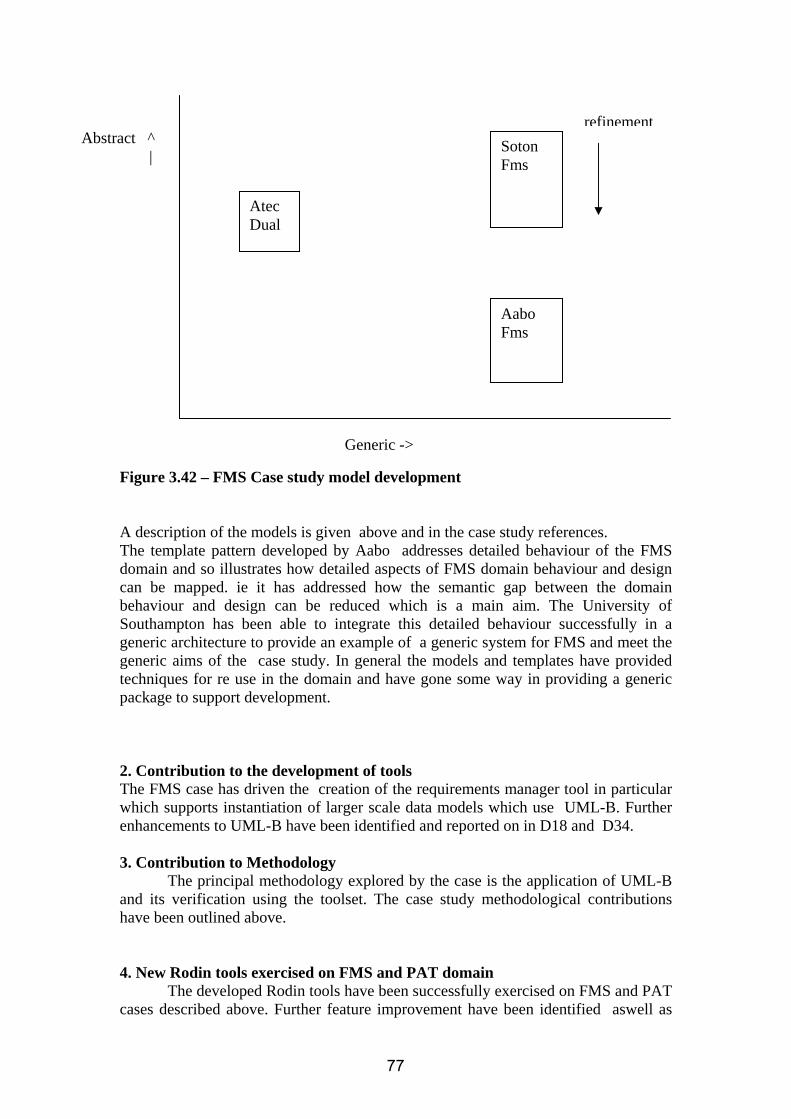
Atec Dual
Soton Fms
Aabo Fms
refinement
Generic ->
Abstract ^ |
Figure 3.42 – FMS Case study model development A description of the models is given above and in the case study references. The template pattern developed by Aabo addresses detailed behaviour of the FMS domain and so illustrates how detailed aspects of FMS domain behaviour and design can be mapped. ie it has addressed how the semantic gap between the domain behaviour and design can be reduced which is a main aim. The University of Southampton has been able to integrate this detailed behaviour successfully in a generic architecture to provide an example of a generic system for FMS and meet the generic aims of the case study. In general the models and templates have provided techniques for re use in the domain and have gone some way in providing a generic package to support development. 2. Contribution to the development of tools The FMS case has driven the creation of the requirements manager tool in particular which supports instantiation of larger scale data models which use UML-B. Further enhancements to UML-B have been identified and reported on in D18 and D34. 3. Contribution to Methodology The principal methodology explored by the case is the application of UML-B and its verification using the toolset. The case study methodological contributions have been outlined above. 4. New Rodin tools exercised on FMS and PAT domain
The developed Rodin tools have been successfully exercised on FMS and PAT cases described above. Further feature improvement have been identified aswell as
77

minor bugs recording. The assessment of the Rodin tools are described in D28 and D34. 5. Domain users evaluation Metrics addressed The evaluation of the models and Rodin methods against the domain criteria for feasibility of the methods has been undertaken and is reported on in D34. We summarize the achievements of the case study development making reference to the intended expectations of the case study. a) )Feasibility of formal methods in application domain including assessment of usability and benefits of object-oriented style of formal specification and rigorous validation and verification This case study development has demonstrated the clear utility of RODIN-based formal methods in the avionics engine control domain. The model is generic w.r.t. static configuration data (context) as well as behaviour. The object-oriented modelling style is a natural fit for both static and dynamic system aspects: hardware components in the system environment (e.g. inputs), as well as system internal components (e.g. detections, confirmations) are modelled as instances, or objects, of a small number of classes (component types). There are many domains (e.g. car engine management, industrial process control, medical intensive care) that afford the same OO modelling philosophy. UML-B provides solid support for OO modelling in terms of class diagrams and statecharts; more diagram types are planned. UML-B diagram and package structures provide component-level structuring. This OO modelling is formalized by its automatic translation to Event-B for formal verification. A desirable future development would be the integration of the formal V&V into UML-B, e.g. representation of syntax errors or failed PO’s in the appropriate diagram, animation state representation on a diagram, etc. b) Development of techniques for re-using formal methods within application domain The case study has demonstrated the facility of RODIN/UML-B modelling for production of reusable models, through architectural principles of genericity, feature-orientation, and OO structuring. A real (Aabo model integration) and a speculative example (space shuttle) of such reuse have been presented. c) Enhancement of UML to B tools to support use of object-oriented formal specification within application domain and to support re-use features As discussed in sections 3.1 – 3.2 UML-B already goes a long way to meet this requirement, although further work is needed for “round-trip engineering”, or the full integration of RODIN V&V with UML-B.
78

3.4. References
[3.1] Laprie, Randell Dependability and its Threats: A Taxonomy [3.2] Dubravka Ilic, Elena Troubitsyna, Linas Laibinis and Colin Snook. Formal
Development of Mechanisms for Tolerating Transient Faults. TUCS Technical Report, No.763, April 2006.
[3.3] RODIN deliverable D2 : Definitions of Case Studies and Evaluation Criteria
Project IST-5111599, November 2004. [3.4] RODIN deliverable D4 : Traceable Requirements Document for Case Studies
Project IST-5111599, February 2005. [3.5] RODIN deliverable D8 : . Initial report on case study developments IST- 5111599, September 2005. [3.6] RODIN deliverable D14 : d7.2 Assessment report IST-5111599, September
2005. [3.7] RODIN deliverable D18 : d7.3 Assessment report IST-5111599, September
2006. [3.8] RODIN deliverable D34 : d7.4 Assessment report IST-5111599, September
2007. [3.9] RODIN deliverable D27 : d1.6 Case study Demonstrators IST-5111599,
September 2007. [3.10] RODIN deliverable D28 : d1.7 Report on assessment of tools and methods
IST-5111599, September 2007. [3.11] Poppleton, M. (2007) Towards Feature-Oriented Specification and Development with Event-B. In Proceedings of REFSQ 2007: Requirements Engineering: Foundation for Software Quality 4542, pp. 367-381, Trondheim, Norway. Sawyer, P., Paech, B. and Heymans, P., Eds. [3.12] Snook, C., Poppleton, M. and Johnson, I. (2006) Towards a method for rigorous development of generic requirements patterns, in Butler, M., Jones, C., Romanovsky, A. and Troubitsyna, E., Eds. Rigorous development of complex fault tolerant systems, pp. 326-342. Springer-Verlag Lecture Notes in Computer Science. [3.13] Snook, C., Poppleton, M. and Johnson, I. (2005) The engineering of generic requirements for failure management. In Proceedings of Eleventh International Workshop on Requirements Engineering: Foundation for Software Quality, pp. 145-160, Oporto. Kamsties, E., Gervasi, V. and Sawyer, P., Eds. [3.14] Real-time failure detection algorithm for the Space Shuttle Main Engine Panossian, H.V. (Boeing North American); Ewing, W.D. Source: IEEE Control Systems Magazine, v 17, n 4, Aug, 1997, p 16-23 ISSN: 0272-1708 CODEN: ISMAD7 Publisher: IEEE
79
[3.15 ] Ilic, D., Troubitsyna, E., Laibinis, L., and Snook, C., “Formal Development of Mechanisms for Tolerating Transient Faults”, In REFT 2005, LNCS 4157, Springer-Verlag, November 2006, pp. 189-209
[3.16] “Achieving requirements reuse a domain specific approach from avionics” Lam:97 Source ” Journal of Systems and Software” year 1997 vol38 no 3 p 197-209. [3.17] Rigourous Open Development Environment for Complex Systems -RODIN
:Description of Work IST-5111599, April 2004 [3.18] Rigorous engineering of product-line requirements: a case study in failure management, Colin Snook, Michael Poppleton, Ian Johnson, to appear in Information and Software Technology, Elsevier, 2007 [3.19] http://www.omg.org/mof/ [3.20] http://www.eclipse.org/modeling/emf/ [3.21] http://www.eclipse.org/m2m/atl/
80

SECTION 4. CASE STUDY 3 – FORMAL TECHNIQUES WITHIN AN MDA CONTEXT
4.1. Introduction This case study is concerned with the formalisation of various subsets of the MITA platform [MITA] (developed in Nokia within the NoTA - Network On Terminal Architecture - project) and, more generally, with the formalisation of the infrastructure and techniques to allow MDA to be used more formally. The objectives of this case study are to:
a Investigate how formal techniques fit into the Model Driven Architecture (OMG MDA) framework as “MDA Mappings”.
b Investigate which techniques are applicable at which stages of platform independence and platform specific models.
c Investigate how to integrate and compare the verification and validation results from the various levels of abstraction.
d Investigate methodological issues relating to formal model development with an emphasis of refinement and retrenchment.
During year three the main focus of this case study has been on validation of the RODIN platform, tools and methods in the context of the MDA framework. All major work on MDA within Rodin was completed by March 2007 as the company ended the NoTA project in December 2006. After that the CS3 team moved to a different domain of a growing importance to Nokia, in which it conducted investigation of the use of the Rodin method and tools in hardware design. This initial evaluation was very successful from the company’s viewpoint (e.g. a prototype of a Rodin tool was developed and demonstrated during year two project review [O3]). All work in this area is now progressing outside of Rodin. The particular formalisms and techniques to be used in the new project are directly related to the Rodin development, although a different language for this work has been chosen. The experience gained by the team in applying formal techniques in the MDA context is being used in this new project. 4.2. Major directions in case study development During year three the CS3 team has specifically focused on performing the following two tasks:
− T1.3.5. Undertake further development steps, primarily integration of other case studies (when applicable) with the MITA framework.
− T1.3.6. Evaluate benefits of formal techniques and tools applied at different stages of the development.
4.2.1. Methodological issues brought up by the case study and methodological advances used in the case study This section briefly discusses major methodological issues addressed and reported by the MITA case study during year three.
81

MDA. Within this case study a method was developed [B1] for introducing formal transformation of platform independent models (PIM) to platform specific models (PSM) in a model driven architecture (MDA) context. While fault tolerance is not introduced in the PIM to make the models reusable for different platforms, the PSM often has to consider platform specific faults. A model transformation of the PIM in order to preserve refinement properties in the construction of the fault tolerant PSM is presented using Event B as a formal framework for the reasoning. UML and B. UML and B were extensively used in the experimental work conducted within this case study to evaluate the pragmatic aspects of the use of formal methods in NoTA. Report [O1] describes three experiments and the experience gained in the use of formal methods in a software engineering environment, that does not completely rely on the top-down stepwise development. These experiments were based on the Use Case/SDL Based Development, UML Based Development and the UML with Explicit Architecting. Directly relevant to Rodin was the extensive use in these experiments of AtelierB, ProB and U2B. Model-based testing. Some initial investigation of the model-based testing was conducted in the context of case study CS3 - see [L1]. The focus mainly was on gaining experience in applying formal methods and model-based testing in an industrial semi-formal environment. The approach used consisted of the two phases: an initial development of a high level model in B, followed by development of use cases in CSP. A number of the use cases were modelled and verified for building a reference model used for testing the implementation. This approach allowed the team to uncover errors that would otherwise most likely not been found, but at the price of creating the system essentially twice. Requirements Change Addressing Fault Tolerance. The team performed some initial investigation into how requirements change and the volatility of specifications can be addressed. The B Method takes the point of view that these are outside the scope of this particular method which concentrates on refinement and decomposition of the models. Some investigation was conducted with retrenchment but without tool and method support this has proven difficult. Requirements change and how to handle this formally still remain a challenge and some investigation has been made in collaboration with Southampton university [O2] Report [O2] describes an example development flow of a simple communicating system involving two communicating processes across a channel. A very abstract or generic communicating system is set up; this could be thought of as any pair of communicating entities or processes via some communication channel, for example, two mobile devices communicating across a UMTS connection or two operating system processes communicating via IPC. As part of the development, we initially assume that the channel is perfect followed by subsequent iterations where we add protection mechanisms to the processes to obtain some degree of fault tolerance with regards to the channel. The aim was to gain an understanding of how the evolution of such a set of requirements would be dealt with using Event-B and refinement. These requirements as they develop do not necessarily refine earlier versions of the requirements - this is to simulate a typical industrial scenario. Analysis of the perfect design by some suitable technique, for example: FMEA, might
82
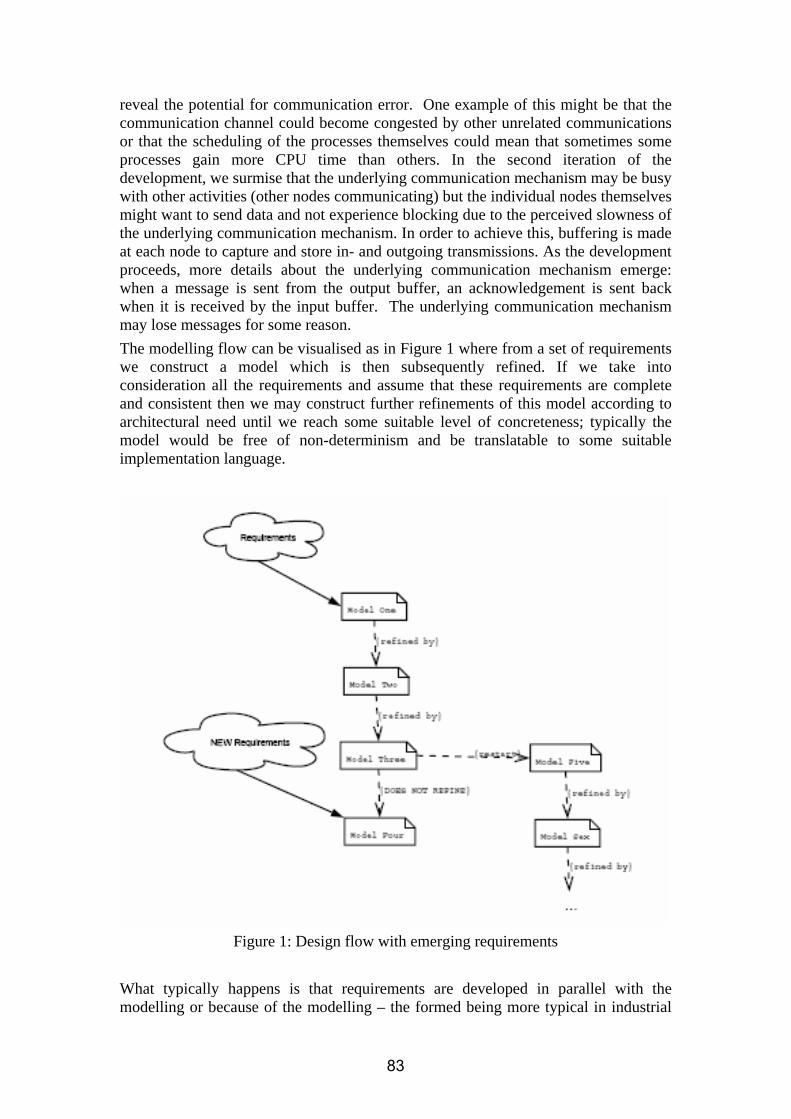
reveal the potential for communication error. One example of this might be that the communication channel could become congested by other unrelated communications or that the scheduling of the processes themselves could mean that sometimes some processes gain more CPU time than others. In the second iteration of the development, we surmise that the underlying communication mechanism may be busy with other activities (other nodes communicating) but the individual nodes themselves might want to send data and not experience blocking due to the perceived slowness of the underlying communication mechanism. In order to achieve this, buffering is made at each node to capture and store in- and outgoing transmissions. As the development proceeds, more details about the underlying communication mechanism emerge: when a message is sent from the output buffer, an acknowledgement is sent back when it is received by the input buffer. The underlying communication mechanism may lose messages for some reason. The modelling flow can be visualised as in Figure 1 where from a set of requirements we construct a model which is then subsequently refined. If we take into consideration all the requirements and assume that these requirements are complete and consistent then we may construct further refinements of this model according to architectural need until we reach some suitable level of concreteness; typically the model would be free of non-determinism and be translatable to some suitable implementation language.
Figure 1: Design flow with emerging requirements
What typically happens is that requirements are developed in parallel with the modelling or because of the modelling – the formed being more typical in industrial
83

environments. During the course of subsequent refinements it becomes apparent that certain requirements cause a change in the model that can not be handled through the refinement process. In Figure 1 this is diagrammatically seen between models three and four. There are techniques such as retrenchment which support the weakening of the model so that the refinement process may continue. However these techniques suffer from complexity and lack of tool support and introduce additional artefacts which complicate the model. The alternative option here is restart the modelling in such a way that the lessons learnt and modelling already performed is not lost (we do not restart modelling from scratch) such that the new line of modelling starts taking into account the new requirements. Modelling continues in the same way as before until either we are required to restart or modelling is complete. In order to mitigate the effects of additional requirements and especially in the case of the introduction of failure modes or fault-tolerance features it is necessary to prepare the initial abstract model in such a way that these additional features can be added to the system through refinement of these additional features. Bluespec. Within this case study some efforts were devoted to combining Bluespec (Bluespec System Verilog) development with formal specification in B [03]. Bluespec is a rule based, declarative hardware specification language based on term rewriting. In this work a hardware specification code was generated from the Event B models developed using the Rodin platform. During this work it was found that this combination offers a sophisticated verification environment with the associated reduction in development errors. Context-awareness. As the computers are evolving to become truly pervasive and ubiquitous, assisting us in our everyday decisions, they need to acknowledge the context they are functioning in. In this strand of work the context is defined as "the setting in which an event occurs", being prevalent and impossible to manufacture. Consequently, the context is the information providing the possibility to interpret data in order to provide more information which in turn enables construction of specified knowledge. As the amount of data is likely to increase in the future, it should be rich enough to enable us to create specified knowledge. [N1] defines a model for implementing these ideas by showing how to refine and add a new context into a system. This is highly relevant to the ubiquitous systems, which typically rely on distributed nodes and communication in which a distinct agent might provide a new context. The ideas regarding refinement of context relies on the work on the wireless sensor networks for which a design framework was developed in [N2] (this work was inspired by the Nokia work on NoTA - see [Z]). The model proposed consists of at least a three layer structure, the application layer fusing the information to knowledge and representing it to the inquirer, the enabler layer propagating and composing the inquiry/data and the raw data producing layer. Moreover, a sensor network constitutes in n segments, the sensor, the en route and the gateway segment. As each layer's emphasis is on one segment, the distributed system layout is obvious; some part(s) must produce the data (and context), another enable communication (and compose relevant data) and one part take care of the user interface providing a concise accurate answer to the inquirer. 4.2.2. Impact of the case study on the platform development During year three an intermediate version of the Rodin platform was used in
84

developing a number of MITA models (see [B1, O2]) and in circuit development with Event B and Bluespec [O3]. Application of the platform has been successful and the results of this work were feed backed to the platform development team. 4.2.3. Impact of the case study on the plug-in developments The experience in using the U2B and ProB plug-ins is summarised in [O1]. This paper reports an experiment in which formal methods (B and B method) were introduced into one of the current development flows of the MITA systems. UMLB (U2B) U2B is a useful tool as any attempt to formalise and use UML in a more structured and rigorous form complete with some form of detailed analysis is more than required. UML as a whole suffers from an incomplete, inconsistent semantics which makes accurate application of the UML problematic at best. Bridging the gap between languages such as UML and B/Event B is critical for general acceptance in industrial environments; though much more work is required on the methodological aspects of such integration. The experience shows that the latter point has not been tackled in a generic enough way in this project; though it can be argued that only specific aspects of this problem such as those pertaining to fault-tolerance were. U2B overall provides a good compromise between the mathematical abstractness of B/Event B to the apparent concreteness of UML (at least to the engineer who forgets the underlying concepts of languages such as UML). However this makes the language more difficult to use without better methodological support - one has to think more in B/Event B terms rather than UML. Application of traditional (sic.) domain modelling techniques or even E-R techniques produces simple enough static or structural models but actions/operations/invariants are required to be written in a form more applicable to B/Event B rather than the object-oriented ideals of UML. While most of the criticism is directed at the support for U2B (something which U2B is not addressing at this time), a more direct criticism can be levelled at the quality and complexity of the proofs generated. Because of the complexity of the mapping from UML and its various structures: class, state, action/operation etc and the OO-mapping overhead the amount of proof obligations becomes much larger than that generated from an equivalent model utilising B/Event B only. ProB ProB provides much necessary support for the default theorem proving and thus verification techniques already present in the Rodin tool. Use of ProB was extremely useful in validating verified models - verification removes certain error conditions and ensures that the model to be validated is "correct". Verification in the style of development used in MITA became a secondary concern with the focus more on establishing that the specification met the customer's demands rather than on establishing the adherence to certain properties. This fits in well with the style of development commonly seen in industry where constructing a model to investigate the properties of the system is not always feasible - ProB and the validation style of development in this sense provides a way of first constructing and demonstrating systems then discovering properties later. The use of ProB was particularly useful with regards to the initial work made with the B language. In use ProB (the Rodin integrated version was not utilised as it was not
85

available at the time) is stable and reasonably fast. Scalability is always an issue but in the sizes of models presented to the tool, no problems regarding this have been seen. B2Bsw Within this case study some efforts were devoted to developing and evaluating an early prototype of the Rodin plug-in supporting circuit development with Event B and Bluespec (see [O3]). This plug-in was successfully integrated in the Rodin platform and used in developing a number of case studies. 4.3. Overview of the achievements of the case study Nokia consider the three years work on the RODIN Case Study 3 to be a partial success. They have obtained
• useful practical results in evaluating feasibility of applying formal methods in the context of MDA
• considerable experience with the use of B in a number of challenging applications
• extended skills in using the Rodin platform and the ProB and UMLB plug-ins as the major support for formal modelling
• good experience in developing Rodin Eclipse plug-ins for the Rodin platform However specific methodological support for Event B and fault-tolerance is still lacking. Other aspects such as mobility, distribution and concurrency still remain unaddressed at this time. References: [B1] P. Boström, M. Neovius, I. Oliver, M. Waldén. Formal Transformation of Platform Independent Models into Platform Specific Models. In Proceedings of the 7th International B Conference (B2007), Besançon, France, LNCS. 4355, pp. 186-200, January 2007. Springer-Verlag.
[MITA] Mobile Internet Technical Architecture. IT Press. 2002.
[L1] V. Luukkala, I. Oliver. Model Based Testing of an embedded session and transport protocols. Presented at the 9th IFIP Int. Conference on Testing of Communication Systems (TESTCOM) and 7th Int. Workshop on Formal Approaches to Testing of Software (FATES). June 26-29, 2007. Tallinn. Estonia.
[N1] M. Neovius, K. Sere, L. Yan, M. Satpathy. A Formal Model of Context-Awareness and Context-Dependency . In Proceedings of 4th IEEE International Conference on Software Engineering and Formal Methods - SEFM 2006, Pune, India September 11-15, 2006
[N2] M. Neovius and L. Yan. A Design Framework for Wireless Sensor Networks. In Proceedings of World Computer Congress - WCC 2006, Ad Hoc networking track, Santiago de Chile, Chile, August 20-25 2006.
[O1] I. Oliver. Experiments and Experiences with UML and B. NRC-TR-2007-006. May 2007. Nokia Research. Finland.
[O2] I. Oliver, J. Colley, M. Butler. An Investigation into the Introduction of Fault
86

Tolerance Concepts with Event B. NRC-TR-2007-Awaiting Number. Nokia Research. Finland. 2007
[O3] I. Oliver. Circuit Development with Event B and Bluespec - RODIN Plug-in Overview. Presented FDL’06 (Forum for specification and design languages). September 19-22, 2006. Darmstadt, Germany
[Z] J. Ziegler, End-to-End Concepts Reference Model, Nokia Research, 2003.
87

SECTION 5. CASE STUDY 4: CDIS AIR TRAFFIC CONTROL DISPLAY SYSTEM
5.1 Introduction CDIS is a computerised system that provides important airport and flight data for the duties of air traffic controllers based at the London Terminal Control Centre. Each user position is a workstation that includes a page selection device (to select CDIS pages) and an electronic display device (to display the selected pages). The original system was developed by Praxis1 in 1992 and has been operational ever since. This system is an example of an industrial scale system that has been developed using formal methods. In particular, the functional requirements of the system were specified using VVSL [5.3] — a variant of VDM [5.2]. The formal development resulted in about 1200 pages of specification documents and about 3000 pages of design documents. The reliability of the delivered system is encouraging for formal methods in large scale system development because the defect rate was a considerable improvement on other similarly sized projects [5.4]. During the first year of the project a useful subset of the CDIS specification was defined, reviewed and distributed. Examples of problem areas in the original CDIS development were identified:
1. The lack of any formal proof in the original development. 2. The difficulty in comprehending the original specification and the difficulty of
modularising the specification. 3. The difficult of dealing with distribution and atomicity refinement.
In Year 2 we focused on addressing items 1 and 2 above, through redeveloping the CDIS subset of Year 1. During this phase we used the B4free tool and a mixture of old style B specification and mimicking some aspects of new methodology recommended by Rodin project. Two different attempts at reworking subset specification commenced: a “translation” approach and a “specify equivalent system from scratch” approach. It was quickly found that the translation approach was not sensible and we focused in Year 2 on the second approach of specifying the system over again. Furthermore we made some preliminary attempt to address the third item by producing a simplified distributed version of CDIS B-specification. This simplified distributed version, later acted as a guideline to extend the idealised model into a distributed version and handle the generated proof obligations. Redeveloping an existing system also allowed us to reflect on the lessons learned from the original development. Our aim was to overcome the lack of comprehensibility and formal proof of the original CDIS development by adopting a methodology that makes use of available B4free tool support. During Year 3 as soon as the early internal versions of the RODIN platform became available we started to port our B models form B4ree tool to the new RODIN tool. In the first instance we attempted to use B2RODIN plug-in to carry out the porting. B2RODIN requires a particular style of B which has not been followed in the second year models. We could modify the second year
1Praxis High Integrity Systems Ltd., U.K.
88

models and then use the B2RODIN plug-in to convert them to RODIN style but we found it more effective to manually input B models into the RODIN tool. In the later stages we extended the CDIS B models with adding two other refinement levels. In addition to this we developed a distributed version of CDIS on RODIN platform. In the next sections we explain this process in more detail. 5.2 Major directions in case study development We briefly discussed in the previous section that our starting point in Year 3 of the project was based on the B models which they have been developed during Year 2. These models were developed using the B4free tool and were mainly based on standard B notation also some attempts to mimic the new Event-B style has been made. In Year 3 we started to port these B models to the new RODIN platform. Both the new Event-B notation and recommended methodology in RODIN are noticeably different from the standard B which supported by B4free. In the light of these changes both in the notation and the methodology we have adopted the second year models to achieve different goals of the project such as reusability, traceability and adaptability. In the first instance we applied the changes to an idealised version of the CDIS and later stage we adapted this approach for the Distributed version. In the following section we review the major achievements during redevelopment of CDIS models on the RODIN platform. 5.2.1 Methodological Considerations Arising from CDIS As stated above, in the first instance we shall be concerned with an idealised view of the system, as modelled in the original core specification. Thus, we model a system that has a centralised database from which information can be retrieved. In order to get a better overview of the entire system, we follow a top-down approach. At the top level, we ignore all of the airport-specific features to produce a specification describing a generic display system. Through an iterated refinement process, we introduce more features into the specification until all of the CDIS functionality is specified. At each step the tool generates a number of proof obligations which must be discharged in order to show that the models are consistent with their invariants. Since each refinement introduces only a small part of the overall functionality, the number of proof obligations at each step is relatively small (approximately less than 20). The purpose of CDIS is to enable the storage, maintenance and display of data at user positions. If we ignore specific details about what is stored and displayed then CDIS becomes a `generic' display system. We begin by constructing a specification for a generic system (which will be, of course, somewhat influenced by the original VDM specification) and, through subsequent refinements, introduce more and more airport-specific details so that we produce a model of the necessary complexity, and reason about it along the way. By providing a top-down sequence of refinements it is possible to select an appropriate level of abstraction to view the system: an abstract overview can be obtained from higher level specifications whilst specific details can be obtained from lower levels. 5.2.1.1 Separation of Context and Machine Based on the new RODIN methodology a model can be divided to two sections, the static and the dynamic parts. The static part which has been named as the Context, contains the definitions of reference Sets, Constants, Axioms and related Theorems. The dynamic part which embodies the main part of the formal method includes all defined Variables and their associated Invariants along with Events which are acting on the variables.
89

In the B models of the second year, although it was not enforced by the B4free tool, in the modelling process the separation between the context and dynamic part of the model has been mimicked. To keep the uniformity between the initial VVL core specification, several simple Contexts such as META_DATA, PAGE_CONTEXT, DISPLAY_CONTEXT, DISPLAY_CONTEXT and MERGE_CONTEXT have been declared. In an attempt to increase the comprehensibility of the B Models, we decided to produce a single Context which contains all the definitions which we need for the first level specification of our system. This change in the RODIN-based B model resulted in a simple flat structure of the first stage context and in our view it has increased the readability of the specification. 5.2.1.2 Simplifying the Machine Structure In the next stage we turned to the main part of our model, the specification Machine. As the new Event-B language now supports less construct in comparison to standard B, we had to make conspicuous changes in the second year models. Some of the changes are as follow:
• Removing input parameters with surrounding parentheses from the front of event’s name and replacing them by variables inside ANY clauses.
• Removing PRE clauses and replace them with ANY clauses. • Removing SELECT clauses and replace them with ANY clauses. • Removing LET clauses and replace them with ANY clauses. • Removing any nested combination of ANY clauses or nested combination of ANY with
PRE/LET/SELECT and replace it with a single ANY clause. • Adding a separate new INITALISATION event • Some other small changes like changing the Remove Operator from set to “\”
Another advantage of the new RODIN tool over the B4ree is that there is no need to define the operation of the refinement levels which they are skip in the specification level. This helps to have a neater model with better readability. In order to get a better overview of the entire system, a top-down approach has been taken during modelling process in Year 2. The same approach has been followed in the third year. At the top level, we ignore all of the airport-specific features to produce a specification describing a generic display system. Through an iterated refinement process, we introduce more features into the specification until all of the CDIS functionality is specified. This procedure is supported by the new RODIN tool. At each step the tool generates a number of proof obligations which must be discharged in order to show that the models are consistent with their invariants. Since each refinement introduces only a small part of the overall functionality, the number of proof obligations at each step is relatively small. 5.2.1.3 Different Approaches to the Record Refinement in CDIS Another aspect of CDIS redevelopment in RODIN tool is the modelling of structured data. The undertaken approach which has been reported in [5.1] is based on deferred set and constant functions. In this approach the structured data would be defined as an abstract set. This serves as the type definition of the structured date or record. According to the modelling needs the record will be refined by introducing the individual fields. The introduction of necessary fields will take place in a stepwise manner by the means of constant functions. The main advantage of this method is that we introduce new record’s fields whenever it is necessary. In addition this approach is compatible with The B- Method general refinement approach. In the rest of this section we discuss the two different paths that we have taken to refine the record types in the RODIN tool.
90

Both in the VDM and second year B models we have structured data types in the form of some records. In the second year B models instead of introducing the whole structure at once we have gradually introduced different fields when they were needed. The main motivations of this approach is to enable a stepwise development of complex record structures (in the spirit of refinement) by introducing additional fields as and when they become necessary. One possible style of using abstract types as records has been followed in the second year models. This approach is based on delaying the introduction of record type to later stages of refinement. In some cases at the abstract level, we might be unaware that a simple (non-record) state variable requires a record structure at a later stage in the development. Hence in the most abstract level we have a set of simple abstract types which they have been defined as deferred set. For example to define the central database of the CDIS system in very abstract level we have defined it as a total function from Attr_id to Attr_value. Both of Attr_id and Attr_value are sets. In the refined model we have replaced the Attr_value with a new type named Airport_attr. Now the new type is a record as following:
Airport_attr :: value: Attr_value Last_update: Date_time
After this refinement the next step is to amend the type of any variables or local parameters which have been affected. For example in the case local parameters which have been defined in ANY statements, we have to define the relation between the abstract parameters and the refined one through the use of witness clauses. Also we found that in many situations the tool can handle the related proof obligation quite easily but in some cases discharging related proof obligation is not very straightforward. Therefore in the third models we have followed a different approach to model records. In this adopted approach during refinement stage we do not change the name of record type. Instead of this we introduce the necessary fields through the use of constant mappings. For example we define the database of the previous case as:
Database = Attr_id → Attrs
And then we define the constant function to relate a value to an attribute. value � Attrs → Attr_value
The main advantage of this approach is that we do not need to use the witness to define the relation between the refined and abstract parameters. In addition to this, it will eliminate the need for having extra invariants. These make the generated proof obligations simpler and as a result some interactive proofs now could be discharged automatically without any user interactions. Another advantage is that increased the comprehensibility of our formal models. 5.2.1.4 Event Splitting and Refinement Another major change that we have introduced in the third year models in comparison to the second year B4free-based models is using the new event splitting facility in the RODIN tool. In the abstract level of CDIS models there are events which represent more that one concrete action in the refined model. An example of this can be seen in refinement level 4 of CDIS where the RELEASE_PAGE of level 3 has been refined by two events which are RELEASE_PAGE and RELEASE_PAGE_OVERLAY. This means that in the more abstract level no difference is observable between these events and therefore they can be seen as one event. It is only possible
91

to distinguish between the two events in the more refined level when we introduce further details into our model. 5.2.1.5 Changing Modelling Style to Achieve Higher Productivity In this section we review some minor changes which we have made in the style of the third year models to achieve higher level of automatic proof or increase the readability and comprehensibility of the B models. Also these changes might be seen very trivial but based on our experiment with the RODIN tool they had great effect either on the comprehensibility of our models or level of automatic proof discharging or even both of them. Some of these changes in style of modelling maybe not directly tailored to the RODIN tool, but from our view point it is very important to document them. This can help other developer to take the advantage of these subtle techniques to improve their modelling. The first style change that we want to point out here is using relation instead of power set. In refinement level 3 of the Year 2 models we have the following declaration:
edd_acks_required � EDD_id � �(Attr_id)
that we have changed it to this one: edd_acks_required � EDD_id ↔ Attr_id
These two declarations are almost identical from the mathematical view point but from modelling view point the story is different. In a very simple comparison between the third and second year models it can be seen that this change has resulted in a lot of simplification in the events which manipulating this variable. For example complex lambda notation and nested restriction has reduced to simple composition. The first effect of this is on the comprehensibility of the model which has been increased. Secondly it has simplified the generated proof obligation in such a way that either could be discharged automatically or with minimum intervention from the user which was not the case with previous style. The second aspect of style related issue is using clarification declaration. In many situations especially when we use local parameters in ANY statements the type of parameter could be implicitly defined through the guards. If the guard if fairly simple it is very easy to find out the type of local parameter. In many practical situations this is not the case and comprehensibility of the model will increase if you add a clarification declaration for these parameters. In our RODIN-based models we have used the method to assist the potential viewers of our model. In addition to this it has helped us to deal with the interactive proofs more easily. 5.2.1.6 Refining the Centralised Specification to a Distributed Model A major criticism of the initial CDIS development was that there was no formal link between the system’s centralised, abstract specification and the distributed design and implementation. During Year 3 we developed an abstract specification which allows us to have multiple views of the centralised database. Each view represents an image of the database values which a user position currently holds. When an update takes place in the centralised database, due to delay in the communication links it takes some time to propagate the changes to the related terminals. Therefore it is perfectly possible that different viewing position have different view of the database values. Some of these views represent a point in the history of the updating. For this reason this approach can be called updating history modelling. Although the multiple view specification is still a centralised model, it provides us with the means to refine to a more realistic distributed version. In the refined model we have replaced the multiple-view system with three different elements. The first element is the main database. Any
92

update first will take place in this database. The second element is a set of local databases which represent the data in the user terminals. The final part of the model is a list of updates that should take place in the user terminals. In this model it is perfectly possible for each terminal to have a different view of the main database which represents a point in the past history of the updates. We are not considering the presented approach as the only realistic abstract specification but it has provided a practical method to formally link the specification to a distributed refinement. We have produced a B model based on this approach in RODIN platform. We consider the refinement of the multiple-view abstract specification to the distributed version as a vertical refinement. In practice there are two different approaches for refining the initial specification. Based on the first approach the vertical refinement can precede any horizontal refinement by which we introduce more features into the model. In the second approach, which we have taken, we postponed the vertical refinement after we have introduced all the requirements into the model. One justification for this could be that going form multiple-view model to distributed model is a design decision and any design aspects should introduced after we have a complete specification. According to what we have presented earlier we have produced a distributed version of CDIS in RODIN platform. This version consists of one specification and five refinement levels. The first four refinements are horizontal refinements and the final level is the vertical refinement as we defined in the previous paragraph. Our experience with the centralised version of CDIS has helped us to develop the distributed version more accurately and quickly. Furthermore we were able to discharge all proof obligations without a major difficulty. 5.2.2 Impact of the CDIS Case Study on the RODIN Platform
The CDIS case study was intended to provide RODIN with the opportunity to compare the capabilities of modern formal methods tools against what was commercially feasible ten years ago. The size of the specification was the first major test of the RODIN tool platform, as it had to highlight any scale-ability issues, which the developed platform might have. Once the specification was developed on the RODIN tool, the secondary aim was to investigate the degree of analysis that is possible for the specification.
Another key test for the tool platform was the degree to which the tool supports the refinement of the specification to a detailed design. The initial CDIS design is concurrent and heterogeneous, with a number of different classes of workstation and system support devices. The concurrency aspects were not described in the original VVL-based specification of CDIS, and during the original development the concurrency aspects were introduced during a manual refinement step. The main drawback of this approach was that there were no formal links between the original specification and the subsequent refinements.
93

As soon as the early pre-release versions of the main RODIN platform reached an acceptable level of stability we started to port the B models produced during year two using the B4free tool.
Initially, we attempted to use the B2RODIN plug-in at this stage to convert and port our models from the B4free based standard B to the RODIN Event-B style. This attempt was unsuccessful and the plug-in did not succeed in producing any Event-B output. Therefore we decided to undertake the above task manually.
As a result a number of issues needed to be tackled; a prime example being the replacement of some standard B constructs, which no longer existed in Event-B, with corresponding constructs and adjusted the modelling style to that recommended by RODIN methodology.
During this stage we provided the developer with a sizable set of feedback and a wish list for future modifications, some of which have yet to be incorporated in the tool. This feedback ranged from interface issues to performance related aspects. Examples are:
• Interface issues: o The interface to some resources of the project like “Log files”, “Comment view” and
“Project resource files” was obscure o The “Problem view” on the window platform did not show mathematics style
characters correctly. o Other interface related issues, where the related view or button/control did not show
up as expected • Some inconsistencies in the early version of the underlying model repositories. • Performance related issues such as slow speed of workspace rebuilding in the earlier
versions. • Lack of help and documentation when early versions released.
Having completed the CDIS specification and early refinement stages, we started to use the RODIN tool prover. Again during this stage we provided a sizable set of feedback to the tool developer. The issues identified were related either to the prover interface or to gap in the internal prover rules. There have been very noticeable improvements in all aspects of the tool. However we still have a wish list of features to be integrated in future tool versions. Some of the additional features, which we recommend to be provided, are:
• A higher level of support for model documentation and multiple commentary lines • An improved editing environment which supports:
o A free style line format, which supports multi-lines, constructs, to facilitate the breaking of log lines across multiple lines.
o Redo and undo facilities o Pop-up help in the form of callouts when holding the mouse over predefined
variables, constants, etc o Auto-complete facilities as provided by other contemporary editors.
5.2.3 Impact of the CDIS Case Study on the Plug-in Developments
UML-B Plug-In This has not been done yet due to lack enough support of plug-in for complex models as CDIS. We expect that this support should be available very shortly.
94

B2RODIN Plug-In This plug-in was needed as we intended to port our second year models to the RODIN platform. Our attempts at that time with early versions of this plug-in were unsuccessful.
ProB Plug-In The current version of this plug-in only supports animation of a simplified version of CDIS. This is because we have used constants mapping in defining records, which is not yet supported by ProB. 5.3 Overview of the Achievements of the CDIS Case Study In this we intended to review the overall achievements of the CDIS case study. During the first year of the project a useful subset of the CDIS specification was defined, reviewed and distributed. Examples of problem areas in the original CDIS development were identified:
1. The lack of any formal proof in the original development. 2. The difficulty in comprehending the original specification and the difficulty of
modularising the specification. 3. The difficult of dealing with distribution and atomicity refinement.
In Year 2 we focused on addressing items 1 and 2 above, though we also made some progress towards dealing with item 3. Two different attempts at reworking subset specification commenced: a “translation” approach a “specify equivalent system from scratch” approach. It was quickly found that the translation approach was not sensible and we focused in Year 2 on the second approach of specifying the system over again. Redeveloping an existing system also allows us to reflect on the lessons learned from the original development. Our aim in this section is to demonstrate how we have attempted to overcome the lack of comprehensibility and formal proof of the original CDIS development by adopting a methodology that makes use of available tool support in an effective way. The major outcome in Year 2 for CDIS was the elaboration of an approach for large scale formal development. The CDIS work heavily influenced work on adding records to Event-B which is described in a paper presented at FM06 in Canada [5.1]. In addition, the approach for large scale formal development elaborated for CDIS partly in Year 2 and more comprehensively in Year 3 will pave the path to development of large scale systems in new Event-B system. Our aims during the third year of the project were as follow:
1. Injection of real industrial requirements into the RODIN platform. We have ported all the second year B models to the RODIN platform. In addition to this we have made several improvements to increase the readability and comprehensibility of the model. We have achieved a higher level of automatic proof discharging. In many cases this has exceeded over ninety percent of the initial generated proofs. Considering the fact that the new RODIN platform now produces more proof obligation such as Well-Definedness (WD) proofs in comparison to the old B4free tool it can be seen as a great achievement. Beside the above mentioned achievements, we have developed the second year models further. They have been extended by introduction some other details in the form of two further refinements levels. Accordingly now we have produced one specification and 6 refinement levels. The refinements levels incorporate both horizontal and vertical refinements.
95

2. Validation of the RODIN model-checking approach on an industrial-scale concurrency specification. In addition to idealised central version of the CDIS which we discussed in the previous point we have developed a distributed version of CDIS. This version includes one specification and 4 refinement levels. We have discharged all of the generated proof obligation ether by the means of automatic prover or the interactive prover.
3. "Stress-testing" of the RODIN tools platform plug-ins in order to ensure they will be useful in an industrial environment. Due to the lack of enough support of the plug-ins for such complex models we have not been able to assess this section. We expect this should be possible very shortly.
4. An industrial view of the success of RODIN, by providing a detailed comparison of the difference between what was achievable 10 years ago in the industrial development of complex systems and what will be achievable by the end of the RODIN project. In a visit to Praxis we have presented our B-Models to experts including some members of the initial development team of CDIS. These have provided the project with very positive and constructive feedbacks. Most of these feedbacks already have been taken into account and we have amended our models accordingly.
References [5.1] N. Evans and M. Butler: Proposal for Records in B, accepted for publication, FM06. http://eprints.ecs.soton.ac.uk/12024/ [5.2] C. Jones: Systematic Software Development using VDM, Prentice Hall, 1990. [5.3] C. A. Middleburg: VVSL: A Language for Structured VDM Specifications, Formal Aspects of Computing, Vol. 1, No. 1, Springer, 1989. [5.4] S. Pfleeger and L Hatton: Investigating the Influence of Formal Methods, Computer, Vol. 30, No. 2, IEEE, February 1997.
96
SECTION 6. CASE STUDY 5: AMBIENT CAMPUS
6.1 Introduction This case study aims at identifying the extent to which various parts of the RODIN approach can provide effective support for the most challenging stages of the formal design process of complex fault-tolerant mobile systems. In particular, the wireless communication medium, on which the implementation part of this case study is based, will necessarily generate a variety of transmission errors leading to a whole range of critical faults that must be tolerated. Moreover, mobile applications will inevitably require dealing with a variety of abnormal and unpredictable events due to system openness, mobility of its participants and their dynamic nature. The overall project work on the Ambient Campus case study has been focusing on:
• elucidation of the specific fault tolerance and modelling techniques appropriate for the application domain,
• validation of the methodology developed in WP2 and the model checking plug-in for verification based on partial-order reductions, and
• documentation of the experience in the form of guidelines and fault tolerance patterns.
More specifically, in this case study we have been investigating how to use formal methods combined with advanced fault tolerance techniques in developing highly dependable Ambient Intelligence (AmI) applications. In particular, we have been developing modelling and design templates for fault tolerant, adaptable and reconfigurable software. The case study covers the development of several working ambient applications (referred to as scenarios) supporting various educational and research activities. These applications are agent-based, and they can run on multiple platforms, such as Personal Computers (PCs), Personal Digital Assistants (PDAs), and smartphones. There are three specific scenarios defined and investigated within this case study:
• Ambient lecture scenario: deals with the activities carried out by teacher and students during a lecture – including questions and answers, and group work among students – using mobile devices (PDAs and smartphones). More details of this scenario can be found in .
• Presentation assistant scenario: covers the activities involved in giving a presentation, where the audience can have the slides shown on their PDA, and they can also raise specific questions on each slide through the PDA.
• Student induction scenario: provides assistance to new students in the registration process at the beginning of the term and in familiarising themselves with the campus environment.
In Year 3, we have focussed on the third scenario where, by using smartdust devices or motes , we can provide a real context-awareness of the agents involved in this
97

scenario. Each student carries a PDA and a mote which periodically broadcasts the identity of the associated student through its Zigbee radio. Each location (room) is equipped with a smartdust receiver that picks up the signal sent by the student’s mote. Therefore, when a student enters a room, his/her presence will be detected by the system, and services available in that location can then be delivered through his/her PDA. Initial work on this scenario is published in . 6.2 Major directions in case study development During Years 1 and 2, we developed a framework called CAMA (Context-Aware Mobile Agents), which consists of: • a set of fundamental abstractions used in the formal development of ambient
systems, • support for the verification of properties of their models, • a formal design of the CAMA middleware using the B method, • an implementation of these systems. In the first two years there was a considerable progress in understanding how agent system development can benefit from formalisation and verification. We consider that formally applied, top-down development, of agent interaction protocols to be the only complete and rigorous software engineering technique in the design of open systems. We recognise that formal methods are not easy to use and the associated costs can often be very high. To facilitate the adoption of RODIN’s formal modelling framework as a mainstream software engineer tool, during Year 3 we have developed a set of abstract design patterns (T1.5.5) that provide general guidance during a formal development and also a tool and a set of refinement patterns that considerably reduce development costs. Refinement patterns are formally described reusable model transformation rules. Pattern correctness is proved once, and all refinements produced using a pattern are automatically correct, which results in a considerable decrease in the number of proof obligations. 2.1. Methodological issues brought up by the case study and methodological advances used in the case study Due to the unique nature of this case study it has been the major driver in developing a number of advanced methodological solutions addressing rigorous stepwise design of mobile open fault tolerant reconfigurable systems. Among the specific issues addressed are reuse by employing refinement and development patterns, ensuring component interoperability through rigorous system development and system adaptivity. This CS has had a major impact on directing the methodological and theoretical research within the overall project, as outlined below. Mobile agent systems (MAS) are complex distributed systems made of asynchronously communicating mobile autonomous components. Such systems have a number of advantages over traditional distributed systems, including: ease of deployment, low maintenance cost, scalability, autonomous reconfiguration and effective use of infrastructure. MAS are distinct enough to require specialised software engineering techniques. A number of methodologies, frameworks and middleware systems were proposed to support rapid development of MAS applications. However, there is as yet no single widely recognised standard and the
98

problem of building large and dependable MAS remains open. As part of our work on this CS, we proposed a formal modelling based approach to developing MAS which should be capable of capturing both the functional model (e.g., what kind of computations an agent is capable of doing) and the behavioral model of an agent (e.g., how an agent moves, how it interacts with other agents, etc.). While it possible to use just the Event-B notation (provided by the RODIN platform) to describe the functional model of an agent and statically verify it, it is quite challenging or even impossible to do the same with the behavioral model. ROLE Drinker
BODY
order = serve ◦ ();
drink = skip
ROLE Pub
VARIABLES int : beer = 0
INVARIANT beer ∈ 0 . . . 10
BODY
serve = IF
beer > 0
THEN
beer := beer − 1;
drink ◦ ()
END
SYSTEM
LOCATIONS pub1, pub2
INVARIANT beer@Pub ≥ drinker@pub
AGENTS
Student(drinker) := move(pub1).order;
Pub(pub) := move(pub1). beer@pubC < 3 ? move(home);
END
Figure 2. Example input to the Mobility Plugin combining Event-B-like state-based specification and a process algebra scenario. In this novel approach, described in [7] and originating from [12], we introduced a hybrid (Event-B combined with constructs inspired by process algebras) high level programming notation for the specification of mobile applications that can faithfully capture both the behavioral and the functional model of an agent (T2.1, T2.2). Formal methods are not a panacea, the main difficulties in using them are complexity of use and scalability. To this end, considerable efforts are devoted to tool support, as exemplified by the RODIN project. However, even with a powerful tool support, formal methods will not be fully accepted as a mainstream software engineering paradigm. The approach we have been working on, called refinement patterns, helps developers in applying formal methods using computer-aided model transformations as part of the rigorous stepwise system development in B. In our approach such transformations are used to capture standardised development steps rigorously introducing well-defined fault tolerance into system. These patterns are formally described and their correctness can be verified to ensure that the model transformations preserve model correctness. Patterns can be applied and undone instantaneously during modelling; they significantly reduce the number of proofs that have to be done to demonstrate model correctness. We believe that once a large number of patterns is accumulated, the automated model transformation supported by
99

patterns will have a profound effect on formal modelling. Pattern instantiation is a little more than a mouse click and a well-designed pattern library can do for formal modelling what class libraries have done for mainstream system development using programming languages. (T2.2) We use the Event-B well-formedness and refinement conditions as the basis for formulating pattern correctness conditions. A pattern is proved to be correct for a whole class of input specifications. In the most general case, this class covers all Event-B specifications. Some restrictions are introduced when formulating a pattern by introducing parameters and requirements. Additional restriction may appear when trying to prove the pattern correctness.
Refinement pattern pattern addinc parameters e req_typing e � Events variable v invariant v � Z action v :� 0..5 action v := v + 1 for e guard v < 10 for e Input specification Pattern application result machine ex variables s invariant s � N initialisation s := 0 events a = begin s := s + 1 end; b = begin s := s + 2 end end
refinement ex_addinc refines a variables s, q invariant s � N, q � Z initialisation s := 0 q :� 0 . . . 5 events a = when q < 10 then s := s + 1 q := q + 1 end; b = begin s := s + 2 end end
Figure 1. A refinement pattern and its application example Refinement patterns are suitable for describing fault-tolerance related design procedures and techniques. One of the benefits of the patterns mechanisms is that it helps to prevent design mistakes when modelling a fault-tolerance mechanism. The two major techniques developed for tolerating software bugs are recovery blocks and N-version programming. These techniques and their variants have been successfully used in many critical industrial applications. We have developed the refinement patterns for these two techniques, demonstrated their correctness and applied in CS5 modelling. We believe that extensive use of patterns in a development gives an indication of development quality provided the individual patterns used in the development are
100

thoroughly analysed and come from respected sources. This is along the line of the blue-prints idea of Event-B design philosophy. Currently, we have developed a considerable number of practical refinement patterns including three fault-tolerance: TMR, NVP and RB. (T2.2 and T2.3) CS5 served as an inspiration for many refinement patterns. We have developed a number of patterns that help to automate design of systems with rich behaviour but shallow functionality. Many mobile agent system protocols and abstractions are can be adequately modelled just by the composition if these patterns. There are also a number of patterns that help introduce inter-agent communication. (T2.4) 2.2. Impact of the case study on the platform development The RODIN platform was used extensively by CS 5 in the work on Year 3 scenario. The modelling of the case study one of the first applications of the platform in the context of realistic, large-scale specifications. Few problems have been found, mainly with the tool interface and these were promptly addressed by the platform developers (bug reports and suggestion were submitted on a regular basis through the sourcefourge tracking facility). 2.3. Impact of the case study on the plug-in developments B2RODIN Plug-In This plugin has been developed to transfer AtelierB projects into the new RODIN platform. The plugin is extremely simple in use and no issues have been found. We have applied the B2RODIn plugin to transfer previous AtelierB and Click'n'Proof developments into the new Rodin Platform. The plugin performance was satisfactory and it is very easy to use. MobilityChecker Motivated and inspired in a direct way by CS5, we developed a plug-in for the RODIN platform based on an automatic verification engine of proven efficiency (developed for high-level Petri nets) that supports the model checking of a given specification of mobile systems. A key issue here is a behaviour preserving translation of the source specification into a high-level Petri net. In our work, we were following a technique used previously in translating two process algebras, KLAIM [8,10,11] and π-calculus [9,13], extended by the modelling of state based transformations coming from Event-B. The verifier checks for deadlock freeness and invariant violations and it is capable to provide feedback in case of discovering an error in the specification. These error traces can be visualised with the help of the included animator, providing further assistance to the designer. ProB Plug-In The integrated version of the ProB tool was to animate various stages of CS5 design directly from the platform. It is a very robust tool that works very well even with large and complex models. The interface is also very good. The only minor downside is that animation of complex models can be somewhat slow. ProB plugin to the platform is essential tool for understanding complex models. Large, involved specifications are hard to read, even more so in Event-B which specifications tend to have large number of events due to absence of sequential composition. Model animation is an efficient and user friendly for model interpretation.
101

Model-Based Testing The theory for model-based testing plug-in is based on user-provided testing scenarios. It employs the Event-B method as a formal framework supporting stepwise system development by refinement. Formal specifications of CS5 are also developed and refined in a stepwise manner. Moreover, testing of the fault-tolerance mechanisms is one of the main issues in CS5. Some of the CS5 models, e.g., middleware specifications, were tested while developing the theoretical basis of model-based testing plug-in. Using the model-based testing approach, test scenarios were identified at the abstract specification level and then refined (together with the corresponding specifications) at each refinement step as shown in Fig. 1. In Fig. 1, the left hand side shows refinements of models Mi, while the right hand side represents refinement of testing scenarios Si.
Figure 1. Our Model-based testing approach using refinement These scenarios also included tests of the incorporated fault tolerance mechanisms. While developing the theory of model-based testing plug-in, CS5 was used as its main case study. As a result, the model-based testing technique adapted to stepwise development of this case study. The described development was done in close collaboration with the team working on CS5. 6.3. Overview of the achievements of the case study In CS5 we developed and investigated a novel approach for modelling and verifying the correctness of complex mobile agent systems. None of the existing languages were capable of capturing the complete behaviour of mobile agents. Our achievement was the development of a single hybrid (Event-B together with a process algebra with mobility characteristics) high level programming notation that is capable of capturing both the behavioral and the functional model of agents. This language has strong theoretical foundations and its structured operational semantics are also presented here. Finally, an efficient model checker has been developed as a plug-in for the RODIN platform. The plan for this tool is to support a significant part of the Event-B notation and also behaviourally rich process algebra expressions. Within CS5, a number of refinement patterns were investigated. We have developed a number of patterns that help to automate design of systems with rich behaviour but shallow functionality. Many mobile agent system protocols and abstractions are can be adequately modelled just by the composition if these patterns. There are also a
102

number of patterns that help introduce inter-agent communications. The modelling of the case study in Year 3 was one of the first applications of the RODIN platform in the context of realistic, large-scale specifications. In this way, the original objectives of this CS have been fulfilled. References [1] B. Arief, A. Iliasov, and A. Romanovsky, "On Using the CAMA Framework
for Developing Open Mobile Fault Tolerant Agent Systems," Proceedings of SELMAS 2006 workshop at ICSE 2006, Shanghai, China 2006, pp. 29-36.
[2] A. Iliasov, A. Romanovsky, B. Arief, L. Laibinis, and E. Troubitsyna, "A Framework for Open Distributed System Design," Proceedings of Computer Software & Applications Conference (COMPSAC 07), Volume II - Workshop Papers, 1st IEEE International Workshop on Software Patterns (SPAC 2007), Beijing, China, IEEE Computer Society, Conference Publishing Services, 27 July 2007, pp. 658-668.
[3] B. Arief, A. Iliasov, and A. Romanovsky, "On Developing Open Mobile Fault Tolerant Agent Systems," in Software Engineering for Multi-Agent Systems V, LNCS 4408, R. Choren, A. Garcia, H. Giese, H.-f. Leung, C. Lucena, and A. Romanovsky, Eds.: Springer, 2007, pp. 21-40.
[4] "Smartdust," online at http://en.wikipedia.org/wiki/Smartdust (last accessed 14 August 2007).
[5] B. Arief, A. Iliasov, and A. Romanovsky, "Rigorous Development of Ambient Campus Applications that can Recover from Errors," Proceedings of Workshop on Methods, Models and Tools for Fault-Tolerance (MeMoT 2007), at the International Conference on Integrated Formal Methods 2007 (IFM 2007), Oxford, UK, 3 July 2007, pp. 103-110.
[6] C. Metayer, J. R. Abrial, and L. Voisin, "Rodin deliverable 3.2. Event-B language," Project IST-511599, School of Computing Science, Newcastle University, available from http://rodin.cs.ncl.ac.uk/deliverables/D7.pdf 2005.
[7] A.Iliasov, V.Khomenko, M.Koutny, A.Niaouris and A.Romanovsky: Mobile B Systems. Proceedings of the Workshop on Methods, Models and Tools for Fault Tolerance, Oxford 2007. Technical Report 1032, School of Computing Science, Newcastle University. (Jun 2007) 17-26.
[8] R.Devillers, H.Klaudel and M.Koutny: Petri Net Semantics of the Finite pi-calculus Terms. Fundamenta Informaticae (2006)
[9] R.Devillers, H.Klaudel and M.Koutny: A Petri Translation of -Calculus Terms. Proc. ICTAC (2006)
[10] R.Devillers, H.Klaudel and M.Koutny: A Petri Net Semantics of a Simple Process Algebra for Mobility. Electronic Notes in Theoretical Computer Science (2006)
[11] R.Devillers, H.Klaudel and M.Koutny: Modelling Mobility in High-level Petri Nets. ACSD (2007)
[12] A.Iliasov, V.Khomenko, M.Koutny and A.Romanovsky: On Specification and Verification of Location-based Fault Tolerant Mobile Systems. Proc. WREFT (2005)
[13] V. Khomenko, M. Koutny and A. Niaouris: Applying Petri Net Unfoldings for Verification of Mobile Systems. Proc. MOCA (2006)
103