Robot Progress Report “Emerson” Crawford Hampson EEL5666: IMDL March 25, 2010.

Final Report
Jamie Unger-Fink
Shoot ‘Em Up
EEL5666: Intelligent Machine Design Lab
Instructors: Dr Arroyo and Dr Schwartz
TAs: Thomas Vermeer and Mike Pridgen
Table of Contents
Abstract ....................................................................................................................................... 3
Executive Summary ...................................................................................................................... 3
Introduction.................................................................................................................................. 3
Integrated System ........................................................................................................................ 4
Mobile Platform ........................................................................................................................... 5
Actuation ...................................................................................................................................... 6
Sensors ......................................................................................................................................... 7
Behaviors ...................................................................................................................................... 8
Experimental Layout and Results ................................................................................................. 8
Conclusion .................................................................................................................................... 9

Abstract
This report details my goals and design process for my robot, Shoot ‘Em Up, which is an
autonomous Beer Pong player. Shoot ‘Em Up will find a red cup, track it and then launch a ball
into that cup.
Executive Summary
The goal of this project was for me to design an autonomous robot that plays the popular
college game of Beer Pong. The basic objective is to shoot a Ping Pong ball into a set of red
cups. To accomplish my goals, I needed a way to detect the cups, a way for the robot to move
around and adjust to its environment and a way to actually launch the ball. One of the things
that was important to me was to have a solid platform large enough to house all of my
electronics, sensors and actuation. I choose to build a base out of plexiglass, secured together
with aluminum studs, and used four omnidirectional wheels to drive the robot. With these
wheels, the robot can drive in any direction without rotational or pivoting first, but also rotates
very nicely. As far as sensors go, I used a CMUCam to detect the color red, an ultrasonic sensor
to determine distance between the robot and the target, and infrared sensors to avoid
obstacles such as walls or objects in the way. When the robot successfully locates the target
and positions itself, a solenoid is used to strike a moment arm, which launches the ball. After
each ball launch, a new ball is automatically loaded into the launcher and it will shoot the next
ball. An LCD screen is used to display out certain important information such as the color
detection data and the ultrasonic range.
Introduction
The original idea for this course was to build a robot that successfully plays the game of Beer
Pong, a popular game among college students. The goal of this game is to shoot a ping pong
ball into your opponent’s red plastic cup, which is placed on an 8-foot long table. To help me to
accomplish this goal, I decided to build a mobile robot that will sit on the end of a table, or for
demo purposes, the floor. In this class, people have tried to build robots to accomplish this and
similar goals, but none of them have had the accuracy I am aiming for. Additionally, I have
found a few machines online that do have decent accuracy, but do not have a mobile platform
and are not considered autonomous robots.

Figure 1: Block Diagram of my system
Integrated System
My system consists of a mobile platform with a CMU camera mounted on top and a ball-
launcher sitting behind it. Inside the structure of my platform, the electronics will be mounted.
The brains of my robot, an ATMEGA128 on the PVR board, will communicate with 4 IR sensors,
1 ultrasonic sensor and a CMU Cam, and act accordingly. When the CMU Cam and sonar find
the target, the robot will position itself and shoot a ping pong ball at the target
Mobile Platform
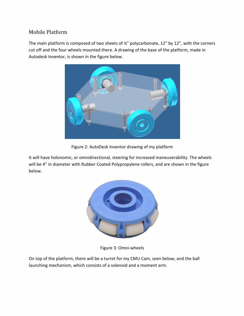
The main platform is composed of two sheets of ¼” polycarbonate, 12” by 12”, with the corners
cut off and the four wheels mounted there. A drawing of the base of the platform, made in
Autodesk Inventor, is shown in the figure below.
Figure 2: AutoDesk Inventor drawing of my platform
It will have holonomic, or omnidirectional, steering for increased maneuverability. The wheels
will be 4” in diameter with Rubber Coated Polypropylene rollers, and are shown in the figure
below.
Figure 3: Omni-wheels
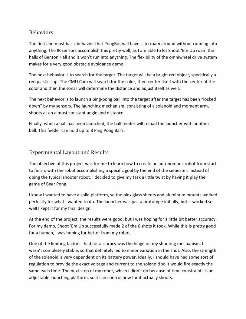
On top of the platform, there will be a turret for my CMU Cam, seen below, and the ball
launching mechanism, which consists of a solenoid and a moment arm.
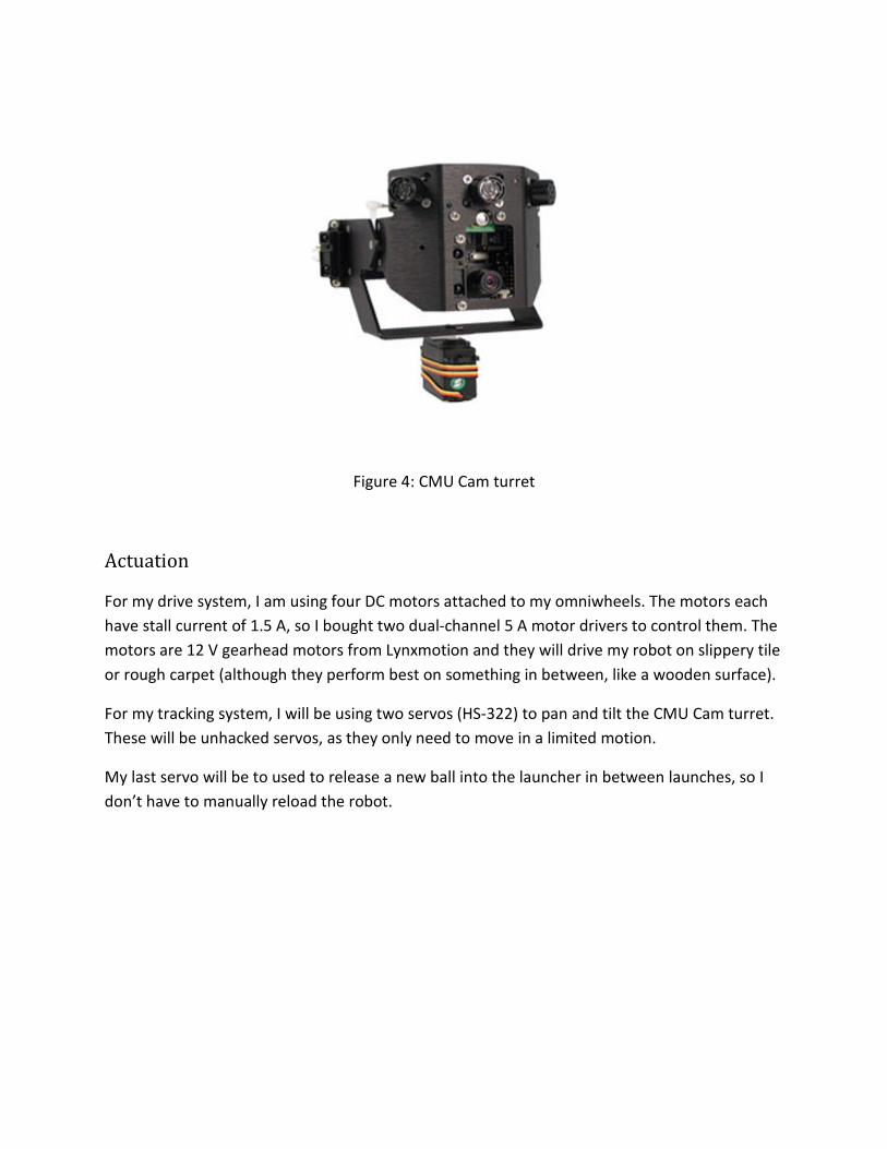
Figure 4: CMU Cam turret
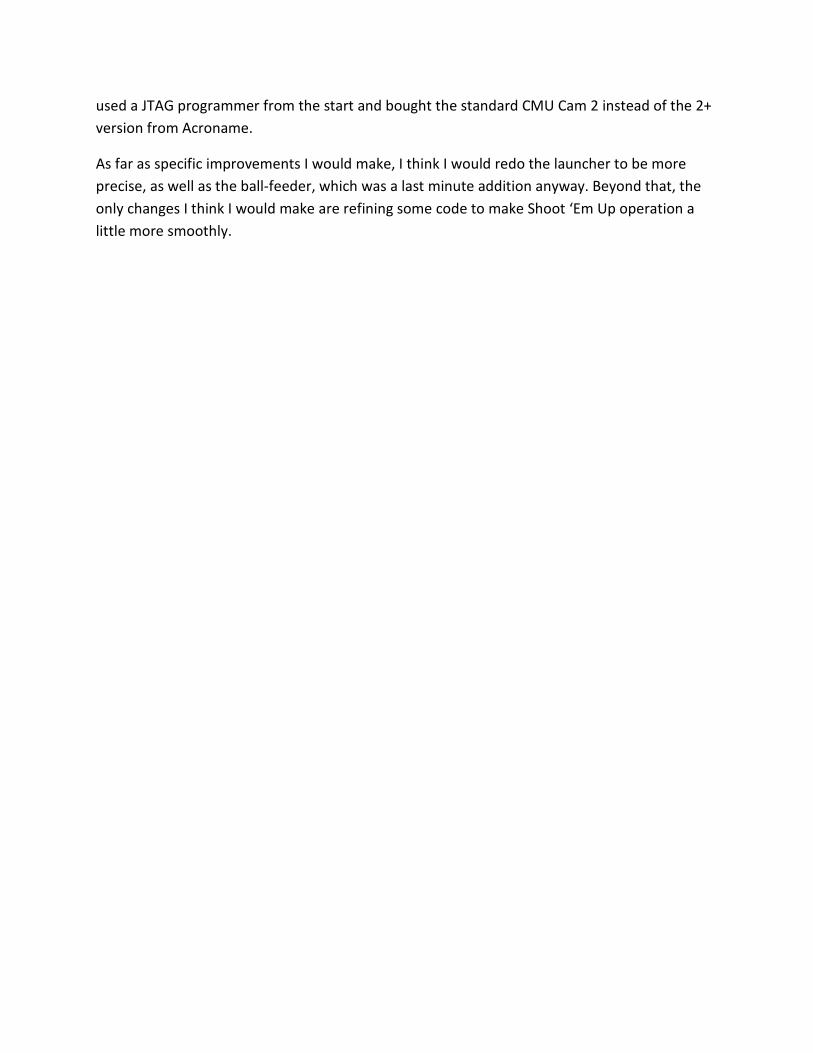
Actuation
For my drive system, I am using four DC motors attached to my omniwheels. The motors each
have stall current of 1.5 A, so I bought two dual-channel 5 A motor drivers to control them. The
motors are 12 V gearhead motors from Lynxmotion and they will drive my robot on slippery tile
or rough carpet (although they perform best on something in between, like a wooden surface).
For my tracking system, I will be using two servos (HS-322) to pan and tilt the CMU Cam turret.
These will be unhacked servos, as they only need to move in a limited motion.
My last servo will be to used to release a new ball into the launcher in between launches, so I
don’t have to manually reload the robot.

Figure 5: Shooting approaches for the game of Beer Pong
I was originally going to use a solenoid to launch the ball, but due to lack of information on
them, I tried other designs. My first attempt was using two door springs; bringing back a panel
and releasing it to hit the ball. The ball only travelled a few feet, much less than I needed it to.
Next, I tried rubber bands, but the worry there is about their durability; whether the material
will degrade over time. At that point, I decided to just buy a solenoid and try it. It actually
worked perfectly and a built a moment arm for it to strike and launch the ball. The solenoid
draws quite a bit of current (almost 5A), so I hooked it up with a relay and I can control it from
the microprocessor.
Sensors
For obstacle avoidance, I am using four IR sensors, one on each side. They will each take up one
ADC port on my microprocessor. I have noticed that as my batteries start to drain, the
performance of the IR sensors degrade significantly. For this reason, I will make sure that I
always have fully charged batteries.
I will be using a combination of sonar and CMU Cam to detect my target. The CMU Cam will find
the bright red target and the sonar will determine how far away it is. My biggest problem over
the course of the semester was the CMU Cam. I have the 2+ model, and there isn’t much
documentation available for this one. Beyond that, the connector that came with it from
Acroname was faulty. Eventually, I finally got the CMU Cam working, and it worked like a
charm. I use the middle mass in the X direction to determine the center of the red blob.
Then I use sonar to detect how far away the target is and adjust the position of the robot
accordingly.
Behaviors
The first and most basic behavior that PongBot will have is to roam around without running into
anything. The IR sensors accomplish this pretty well, as I am able to let Shoot ‘Em Up roam the
halls of Benton Hall and it won’t run into anything. The flexibility of the omniwheel drive system
makes for a very good obstacle avoidance demo.
The next behavior is to search for the target. The target will be a bright red object, specifically a
red plastic cup. The CMU Cam will search for the color, then center itself with the center of the
color and then the sonar will determine the distance and adjust itself as well.
The next behavior is to launch a ping-pong ball into the target after the target has been “locked
down” by my sensors. The launching mechanism, consisting of a solenoid and moment arm,
shoots at an almost constant angle and distance.
Finally, when a ball has been launched, the ball feeder will reload the launcher with another
ball. This feeder can hold up to 8 Ping Pong Balls.
Experimental Layout and Results
The objective of this project was for me to learn how to create an autonomous robot from start
to finish, with the robot accomplishing a specific goal by the end of the semester. Instead of
doing the typical shooter robot, I decided to give my task a little twist by having it play the
game of Beer Pong.
I knew I wanted to have a solid platform, so the plexiglass sheets and aluminum mounts worked
perfectly for what I wanted to do. The launcher was just a prototype initially, but it worked so
well I kept it for my final design.
At the end of the project, the results were good, but I was hoping for a little bit better accuracy.
For my demo, Shoot ‘Em Up successfully made 2 of the 6 shots it took. While this is pretty good
for a human, I was hoping for better from my robot.
One of the limiting factors I had for accuracy was the hinge on my shooting mechanism. It
wasn’t completely stable, so that definitely led to minor variation in the shot. Also, the strength
of the solenoid is very dependent on its battery power. Ideally, I should have had some sort of
regulation to provide the exact voltage and current to the solenoid so it would fire exactly the
same each time. The next step of my robot, which I didn’t do because of time constraints is an
adjustable launching platform, so it can control how far it actually shoots.

Figure 6: Photograph of final design
Conclusion
Throughout this semester, I definitely put more work into this class than anything I’ve ever
done before. At the start, I didn’t get moving early enough, I was just conceptualizing and not
actually getting anything done. Before spring break, I was basically just testing components
individually, trying to get them working on their own. From the week before spring break until
the week after, I put together my entire platform, mounted all my electronics and motors and
the hard work followed from then until the final demo.
Some of the limitations I faced were faulty hardware that I spend way too long trying to debug.
I originally wanted to program my robot via ISP, but later learned that wasn’t possible with the
PVR boards. I also attempted to use a graphic LCD for a nicer and more robust display, but after
trying for a few weeks at it, I had to move on to something else.
The biggest single challenge of this robot was to get the CMU Cam successfully working, but
once I did, the results were incredible. It ended up working exactly how I wanted it to, and it
served its purpose in finding the red target every time.
If I had to start over, I would have actually gotten started earlier. In fact, I would have started
over winter break instead of waiting until class began to think of an idea. Also, I would have
used a JTAG programmer from the start and bought the standard CMU Cam 2 instead of the 2+
version from Acroname.
As far as specific improvements I would make, I think I would redo the launcher to be more
precise, as well as the ball-feeder, which was a last minute addition anyway. Beyond that, the
only changes I think I would make are refining some code to make Shoot ‘Em Up operation a
little more smoothly.