Final Report Goo d practice in construction and demolition ... practice in construction and... ·...
56
Final Report Good practice in construction and demolition materials recovery facilities A review of UK MRFs to identify, and to encourage MRF operators to adopt, good practice in the recovery of non-inert C&D waste materials. Project code: MRF115 Research date: 13 October 2008 to 27 February 2009 Date: October 2009
Transcript of Final Report Goo d practice in construction and demolition ... practice in construction and... ·...

Final Report
Good practice in construction and
demolition materials recovery
facilities
A review of UK MRFs to identify, and to encourage MRF operators to adopt, good practice in the recovery of non-inert C&D waste materials.
Project code: MRF115
Research date: 13 October 2008 to 27 February 2009 Date: October 2009

WRAP helps individuals, businesses and
local authorities to reduce waste and
recycle more, making better use of
resources and helping to tackle climate
change.
Written by: Dan Eatherley and Steve Slater
Front cover photography: Mechanical grab pre-sorting construction and demolition waste.
WRAP and Oakdene Hollins Ltd believe the content of this report to be correct as at the date of writing. However, factors such as prices, levels of recycled content and
regulatory requirements are subject to change and users of the report should check with their suppliers to confirm the current situation. In addition, care should be taken
in using any of the cost information provided as it is based upon numerous project-specific assumptions (such as scale, location, tender context, etc.).
The report does not claim to be exhaustive, nor does it claim to cover all relevant products and specifications available on the market. While steps have been taken to
ensure accuracy, WRAP cannot accept responsibility or be held liable to any person for any loss or damage arising out of or in connection with this information being
inaccurate, incomplete or misleading. It is the responsibility of the potential user of a material or product to consult with the supplier or manufacturer and ascertain
whether a particular product will satisfy their specific requirements. The listing or featuring of a particular product or company does not constitute an endorsement by
WRAP and WRAP cannot guarantee the performance of individual products or materials. This material is copyrighted. It may be reproduced free of charge subject to the
material being accurate and not used in a misleading context. The source of the material must be identified and the copyright status acknowledged. This material must
not be used to endorse or used to suggest WRAP’s endorsement of a commercial product or service. For more detail, please refer to WRAP’s Terms & Conditions on its
web site: www.wrap.org.uk
Good practice in construction and demolition materials recovery facilities 3
Executive summary
WRAP (Waste & Resources Action Programme) is leading a drive to halve the amount of construction, demolition
and excavation (CD&E) waste sent to landfill by 2012. Many construction contractors, demolition and excavation
companies and their major clients and waste managers are signing up to The Construction Commitments: Halving
Waste to Landfill which commits them to playing their part in halving the amount of construction,
demolition and excavation waste going to landfill by 20121. In order to achieve this, the construction
industry is encouraged to work closely with waste management companies (WMCs) to identify and implement
good practice across the waste supply chain. From the point of waste arising on C&D project sites through to the
delivery of quality materials at the re-processing facilities, the successful retrieval from these waste streams of
materials for re-processing is a vital element in achieving the stated aims. Methods for recovering and recycling
inert wastes, such as aggregates, soils and concrete, are well-established in the UK. However, despite the
introduction of various regulatory and fiscal measures, the volume of non-inert wastes disposed to landfill
remains high. Such materials include cardboard and plastic packaging, plastic products, wood, insulation, some
ferrous and non-ferrous metals, ceramic materials and bio-organics.
This report describes the findings of a review which focused on a key element of the waste supply chain, namely
the contribution made by Materials Recovery Facilities (MRFs). The review sought to identify, and to encourage
MRF operators to adopt, good practice in the recovery of non-inert C&D waste materials.
The working method for the review included visiting 15 UK sites thought likely to demonstrate good practice in
part or all of their operations. To gain a wider European perspective, visits were also made to three C&D MRFs in
the Netherlands - a country considered advanced in its treatment of C&D waste. Additional insights were
gathered through telephone interviews with three further MRF operators, discussions with sorting technology
manufacturers and suppliers, and at two workshops with waste management and construction companies
organised by WRAP.
The definition of ‘good practice’ is subjective, and opinions within the industry differ as to whether or not a
particular practice is ‘good’. This report describes good practice where this is undisputed by all stakeholders and,
for those elements of MRF operations where processes or management systems are disputed, the report reviews
the arguments for and against such practices.
While certain elements of good practice were exhibited by all the sites visited, none were considered exemplars in
all aspects. Thus the current report does not focus on any specific sites but rather highlights elements of good
practice identified from all the MRFs visited or interviewed. In effect it describes an exemplar MRF in which key
elements of the processes associated with the recovery of quality non-inert C&D waste recyclates are identified.
It was not possible to visit all of the UK’s C&D MRFs during the review, and we accept that examples of good
practice will also exist in many sites not covered by the review.
1 More information on The Construction Commitments: Halving Waste to Landfill is available at www.wrap.org.uk/construction

Good practice in construction and demolition materials recovery facilities 4
Contents
1.0 Introduction and working method .............................................................................................6
1.1 Introduction to this report ................................................................................................... 6
1.2 Structure of the report ........................................................................................................ 6
1.3 Methodology and scope ...................................................................................................... 7
1.4 Site visits and interviews ..................................................................................................... 7
2.0 Introduction to the C&D MRF process........................................................................................9
2.1 The typical MRF.................................................................................................................. 9
2.2 Acceptance of C&D waste onto the MRF site ......................................................................... 9
2.3 Initial waste inspection and preparation.............................................................................. 11
2.4 Up-front automated screening process ............................................................................... 12
2.5 Material recovery from the undersized fraction .................................................................... 13
2.6 The picking cabin ............................................................................................................. 13
2.7 Onward destinations for non-inert material recovered by MRFs............................................. 13
3.0 Managing supplies ....................................................................................................................18
3.1 Meeting the supplier’s requirements ................................................................................... 18
3.2 ‘Know your waste’ ............................................................................................................ 18
3.3 Source-segregation vs. mixing waste.................................................................................. 18
3.4 Customer education and training........................................................................................ 20
3.5 Reuse and remanufacture ................................................................................................. 20
3.6 Generating business ......................................................................................................... 20
3.7 Recovery rate measurement and reporting ......................................................................... 21
3.8 Problem materials............................................................................................................. 21
4.0 Material flows............................................................................................................................24
4.1 At the C&D site ................................................................................................................ 24
4.2 At the weighbridge ........................................................................................................... 24
4.3 Initial management of waste ............................................................................................. 24
4.4 Introducing material into the MRF process .......................................................................... 26
4.5 Monitoring and optimising MRF performance....................................................................... 26
5.0 People........................................................................................................................................28
5.1 Hiring staff....................................................................................................................... 28
5.2 Motivating and training staff .............................................................................................. 28
5.3 Monitoring staff performance............................................................................................. 29
6.0 Equipment and technology .......................................................................................................32
6.1 Limits to automation ......................................................................................................... 32
6.2 Initial screening equipment ............................................................................................... 33
6.2.1 Trommels ............................................................................................................ 33
6.2.2 Vibratory screens ................................................................................................. 34
6.2.3 Disk screens and star screens................................................................................ 35
6.3 Magnets .......................................................................................................................... 36
6.4 Picking cabin equipment.................................................................................................... 36
6.5 Water separation equipment.............................................................................................. 37
6.6 Air separation equipment .................................................................................................. 37
6.7 Shredders ........................................................................................................................ 38
6.8 Advanced equipment ........................................................................................................ 39
6.9 Equipment maintenance.................................................................................................... 39
7.0 Managing outputs .....................................................................................................................42
7.1 The importance of good outputs ........................................................................................ 42
7.2 Flexibility ......................................................................................................................... 42
7.3 Contracts with re-processors ............................................................................................. 43
7.4 Care of output materials.................................................................................................... 43
7.5 Energy recovery ............................................................................................................... 44
8.0 Environmental impacts and health and safety.........................................................................47
8.1 Reducing environmental impacts........................................................................................ 47
8.2 Reducing health and safety risks ........................................................................................ 49

Good practice in construction and demolition materials recovery facilities 5
Appendix 1: Contact details for MRFs visited or interviewed..............................................................51
Appendix 2: Items reviewed during site visits.....................................................................................54
Appendix 3: Gypsum-containing materials waste management .........................................................55
Abbreviations
C&D construction and demolition
C&I commercial and industrial
CCTV closed circuit television
CHP combined heat and power
Defra Department for the Environment, Food and Rural Affairs
EA Environment Agency
EfW energy from waste
EWC Code European Waste Catalogue Code
ESA Environmental Services Association
H&S health and safety
HDPE high density polyethylene
ISO International Organization for Standardization
KPI key performance indicator
LAP National Waste Management Plan (Netherlands)
LDPE low density polyethylene
LOW List of Waste (replaced EWC codes)
LSU lights separation unit
MDF medium-density fibreboard
MRF materials recovery facility
NIEA Northern Ireland Environment Agency
OHSAS Occupational Health and Safety Management Systems
PET polyethylene terephthalate
PP polypropylene
RDF refuse-derived fuel
RORO roll-on-roll-off skip
RRS Recyclers Registration Service
SEPA Scottish Environment Protection Agency
SSWAT Site Specific Waste Assessment Tool
SWMP Site Waste Management Plan
uPVC unplasticized polyvinyl chloride
WEEE waste electrical and electronic equipment
WTS waste transfer station
Acknowledgements
The authors thank all the MRF operators visited for this project for freely giving up their time, offering valuable
advice and allowing us to photograph their operations. We are especially grateful to Wayne Clarke of Premier
Waste (Birmingham), Greg Walton of Shanks Waste Management (Kettering) and Peter Jukes of Smiths
(Gloucester) for reviewing a draft of this report and to Mark McAspurn of Ahern, Mick Crossan of Powerday and
Jan Robert van Vleen of Shanks Nederland for their assistance with case study material. In addition, the project
also benefited from input of Andrew Liddell of Ace Liftaway (Romsey, Hampshire).

Good practice in construction and demolition materials recovery facilities 6
1.0 Introduction and working method
1.1 Introduction to this report Halving waste to landfill is a construction sector goal which supports the Strategy for Sustainable Construction in
England, the Scottish Government’s Zero Waste policy and the Welsh Government’s policy on Zero Waste. In
consultation with industry, WRAP has developed a voluntary agreement which demonstrates corporate
contributions to the Construction Commitments: Halving Waste to Landfill, by 2012, with actions to halve the
amount of construction and demolition (C&D) waste that is currently being sent to landfill. Individual companies
are not expected to halve their own waste going to landfill, but rather to prove year-on-year reductions in
tonnages of waste landfilled. More information on The Construction Commitments: Halving Waste to Landfill is
available on the following website: www.wrap.org.uk/construction.
The successful recovery and processing of C&D waste by operators of Material Recovery Facilities (MRFs) is key
to achieving the Having Waste to Landfill targets. The construction industry, waste management companies and
material re-processors are encouraged to work together to identify and implement good practice across the waste
supply chain, from the point of waste arising on project sites through to the delivery of quality materials at the
re-processing facilities.
Methods for recovering and recycling inert wastes (such as aggregates, soils and concrete) are well-established in
the UK. However, despite the introduction of various regulatory and fiscal measures, the volume of non-inert2
waste (such as cardboard and plastic packaging, plastic products, wood, insulation, ferrous and non-ferrous
metals, ceramic materials and bio-organics) disposed to landfill remains high.
This report describes the findings of a review which focused on a key element of the supply chain – namely the
contribution made by MRFs3. With its sophisticated manual and automated segregation systems, the MRF is a
recent arrival on the waste management scene. In the past, beyond some limited recovery of aggregate and
metal, waste management companies serving C&D customers would simply consolidate waste at a site prior to
disposal to landfill. Today, the high cost of landfill and increased markets for recyclates have incentivised the
recovery of a wider volume and variety of materials. The Construction Commitments: Halving Waste to Landfill
initiative will further drive improvement in the MRF process.
Carried out by consultants Oakdene Hollins Ltd, the review sought to identify - and to encourage MRF operators
to adopt - good practice in the recovery, handling and sorting of non-inert C&D waste materials.
1.2 Structure of the report After an outline of the methods used in the study (Section 1.3), and an introduction to the C&D MRF process
(Section 2.0), this report highlights good practice in the way MRF operators work with their waste suppliers
(Section 3.0), and move the material through their plant (Section 4.0). Sections 5.0 and 6.0 describe approaches
to getting the best out of people and automated sorting systems, while Section 7.7.0 covers the management
and onward movement of material outputs from the facility. The report concludes with ways to reduce
environmental impacts and health and safety risks at a C&D MRF (Section 8.0).
Four stand-alone case studies are included which describe:
� the findings of an industry stakeholder workshop run by WRAP;
� ways to motivate staff;
� a MRF which is investing heavily in automation; and
� good practice in the Netherlands.
2 The term ‘active waste’ is also used to describe non-inert arisings since they decay in landfills or contaminate land.
3 Not all the companies visited classified themselves as ‘MRFs’. Some felt the term was more appropriately used to describe a facility designed for processing a limited range of household recyclables rather than all types of waste arising at C&D sites. However, this opinion was held by a minority of informants and this report uses the word MRF in the latter sense. Note, that many of the findings here apply also to waste transfer stations, since the distinction between these and MRFs is increasingly blurred. In the past, WTSs were used solely to consolidate waste material prior to onward movement (originally to landfill), but today many of the recovery processes occurring at MRFs are also performed by WTSs. Similarly, several MRFs visited for this study also included areas where additional waste was bulked-up, baled and moved on without specific material recovery.

Good practice in construction and demolition materials recovery facilities 7
1.3 Methodology and scope In carrying out the review, an initial database of over 600 UK MRFs and waste transfer stations (WTSs) was
compiled using information supplied by the countries’ regulatory authorities (EA, SEPA and NIEA). The database
obtained was a listing of all MRFs taking municipal, commercial/industrial (C&I), and construction/demolition
(C&D) waste. In the C&D sector, it did not distinguish sites processing exclusively non-inert C&D waste from
those handling only the inert fractions of construction waste. Nevertheless, from the database and from
supplementary information obtained from Oakdene Hollins’ and WRAP’s industry contacts, a list was drawn up of
18 UK sites thought likely to demonstrate good practice in part or all of their operations. This list is designed to
reflect conditions in different regions of the country with varying local waste arisings, disposal routes and other
factors. MRFs in both urban and rural settings were selected since operations and profitability are affected by the
proximity and cost of landfill. It was not possible to visit all C&D MRFs in the UK during our study, and we
recognise that good practice in C&D MRF operations will also exist in many sites we were unable to visit.
Between November 2008 and March 2009, fifteen of the shortlisted UK MRFs were visited, and phone interviews
conducted with a further three. To gain a wider European perspective, visits were also made to three C&D MRFs
in the Netherlands - a country considered advanced in its treatment of C&D waste.
Information was also gathered through telephone interviews with technology manufacturers or suppliers including
Komptech UK Ltd, General Kinematics, FTL Engineering Systems Ltd and Lindner-Recyclingtech GmbH.
Information on regional differences in waste management regulation was provided by contacts at the Scottish
Environment Protection Agency (SEPA) and the Northern Ireland Environment Agency (NIEA). Information on
the requirements for refuse-derived fuel (RDF) was supplied by Fibre Fuel Ltd and ITI Energy Ltd.
Additional insights were gained from two workshops organised by WRAP attended by representatives of the
waste management and construction industries.
All elements of good practice in the MRF operation were considered. These ranged from contractual and
logistical relationships with both the MRF feedstock suppliers (i.e. construction and demolition contractors and
their clients) and material re-processing customers (e.g. paper mills, scrap metal and plastics recyclers), to the
operational elements of receiving, storage, processing and delivering quality recyclates to the re-processors. The
use of management systems, advanced technology, automatic versus manual sorting, and human resources
policies were also reviewed.
Clearly, what constitutes ‘good practice’ is subjective; opinions within industry differ as to whether a particular
practice is good or not. Examples of the latter, where divergent views were offered during our study, are the
pre-sorting of waste at construction sites and the use of automation in preference to manual picking. For the
purpose of this report we focussed on those practices that appeared, directly or indirectly, to deliver recovery of
greater ratios or higher value of recyclates to the re-processors, or which achieve improved social responsibility
(particularly environmental impacts and health and safety benefits) in their operations. Where opinions of
operators on any specific practice seemed polarised, the report sets out both arguments for and against adopting
that practice.
While certain elements of good practice were exhibited by all the sites visited, none were thought to be
exemplars in all aspects. For this reason the current report does not focus on any specific sites but rather
highlights elements of good practice identified from all the MRFs visited.
1.4 Site visits and interviews As noted above, from the target list of C&D MRFs drawn up, visits were conducted to 15 sites in the UK:
� Ahern Waste Management Services, West Thurrock, Essex;
� Commercial Recycling, Wimborne, Dorset;
� Eastern Waste Disposal, Brightlingsea, Essex;
� Ethos Recycling, Uxbridge, Middlesex;
� JBT Waste Services, Bedlington, Northumberland;
� M & M, Oxford;
� Malcolm Construction Services, Glasgow;
� McGraths, London;
� Nick Brookes, Wardle, Cheshire;
Good practice in construction and demolition materials recovery facilities 8
� Pearsons, Thetford, Norfolk;
� Powerday, London;
� Premier Waste, Birmingham;
� Shanks, Kettering, Northamptonshire;
� Smiths, Gloucester; and
� William Tracey, Glasgow.
Phone interviews were conducted with:
� John Wade Group, Darlington, Co. Durham;
� Irish Recycling Services, Belfast;
� McKinstry Skip Hire, Crumlin, Co Antrim.
Three further sites in the Netherlands run by Shanks Waste Management Group were visited, providing a
Continental perspective:
� Icova B.V., Amsterdam;
� Smink Groep, Amersfoort; and
� Van Vliet Groep, Nieuwegein.
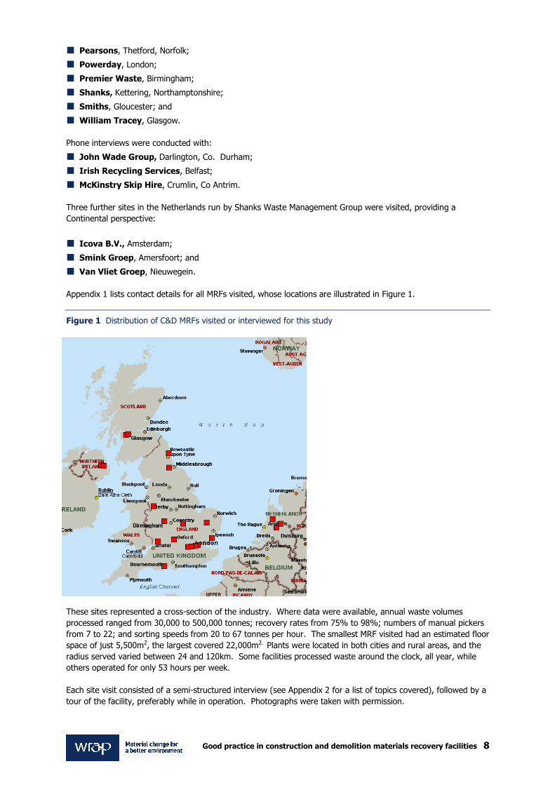
Appendix 1 lists contact details for all MRFs visited, whose locations are illustrated in Figure 1.
Figure 1 Distribution of C&D MRFs visited or interviewed for this study
These sites represented a cross-section of the industry. Where data were available, annual waste volumes
processed ranged from 30,000 to 500,000 tonnes; recovery rates from 75% to 98%; numbers of manual pickers
from 7 to 22; and sorting speeds from 20 to 67 tonnes per hour. The smallest MRF visited had an estimated floor
space of just 5,500m2, the largest covered 22,000m2. Plants were located in both cities and rural areas, and the
radius served varied between 24 and 120km. Some facilities processed waste around the clock, all year, while
others operated for only 53 hours per week.
Each site visit consisted of a semi-structured interview (see Appendix 2 for a list of topics covered), followed by a
tour of the facility, preferably while in operation. Photographs were taken with permission.

Good practice in construction and demolition materials recovery facilities 9
2.0 Introduction to the C&D MRF process
2.1 The typical MRF This section outlines the typical methods by which construction and demolition wastes are accepted and processed, and recovered materials moved on, by Materials Recovery Facilities. Every C&D MRF differs in its particular layout and combination of manual and automated sorting processes.
However, Figure 2 illustrates the typical sequence in which output materials are recovered.
Figure 2 The typical C&D MRF process
WeighbridgeAutomated Pre-sort
(trommel or vibratory screen)
Tipping Bay
Magnet
Picking Cabin
Air Knife
FERROUS METAL
SOIL
WOOD PLASTIC NON-FERROUS METAL
CABLES
PAPER& CARDWEEE, PLASTER-BOARD,
MATTRESSES, LARGE METAL, NUISANCE
MATERIALS
RESIDUALS: FINE PAPER,
PLASTIC, WOOD
AGGREGATES
Copyright Oakdene Hollins Ltd. 2009
Landfill, Energy Recovery
Recycled
Recycled or Landfilled
Nails
Process Flow
Magnet
Wind Shifter
Small Fraction
Large Fraction
RESIDUALS: FINE PAPER,
PLASTIC, WOOD
Landfill, Energy Recovery
Wood Shredder
Shredded Wood
2.2 Acceptance of C&D waste onto the MRF site Waste from construction and demolition sites is usually transported by road to the MRF. Some operators accept
waste by rail, canal, or both (Figure 3). One site estimates for the period of one job, its rail-link to a reprocessor
site every day saved some 80 truck journeys of 67 miles.

Good practice in construction and demolition materials recovery facilities 10
Figure 3 Canal and rail links at a MRF
For convenience, we refer to skips only from this point, although MRF operators will hire out a range of other
waste containers including domestic-sized wheelie-bins, eurobins, roll-on-roll-off skips (ROROs), grab bags, sacks,
grab lorries, and bulker lorries.
At the weighbridge (Figure 4) the gross weight of the skip-truck is measured. The skip-truck driver also hands
over a Duty of Care note to the weighbridge office detailing the type of waste using a 6-digit code from the List
of Waste, a categorisation system which has replaced the European Waste Catalogue (EWC). Duty of Care notes
require both the waste producer and receiver to demonstrate awareness of the quantity and type of waste being
transported and transferred4. This information is communicated by two-way radio to staff in the tipping area, for
verification. The skip is emptied and the truck exits the site, again via the weighbridge in order to calculate the
net weight of material tipped. The driver is also given a ticket stating this figure. Data on weight and LOW code
are used to generate invoices.
Figure 4 A weighbridge
4Defra is planning to lead a full review of the code of practice governing Duty of Care in England and Wales for Waste Carriers and Brokers in 2009. Any updates to the rules will be published first on the Defra website: www.defra.gov.uk/environment/waste/legislation/duty.htm. Further information on compliance is available at: http:// www.netregs.gov.uk/netregs/63197.aspx

Good practice in construction and demolition materials recovery facilities 11
2.3 Initial waste inspection and preparation Waste pre-sorted at the construction site can bypass the MRF’s normal processes and be directly tipped into the
appropriate bulk storage bay ready for transfer to a bulk container for onward shipment to the re-processor,
provided it is of suitable quality and is in a collection container that facilitates efficient handling.
Mixed wastes will be tipped into an area for subsequent loading into the processing line (Figure 5). In this
tipping area, any materials unsuitable for the general MRF process are removed for separate management.
These include hazardous materials such as asbestos, oils, contaminated soils, chemicals, waste electrical and
electronic equipment (WEEE), batteries, and treated wood, as well as gypsum-containing materials, and awkward
items such as doors and mattresses (Figure 6).
Figure 5 A recently tipped skip
By law, the MRF operator should be made aware of any hazardous waste coming to the plant before it leaves the
C&D site. The relevant environmental licensing authority (i.e. EA in England & Wales, SEPA in Scotland, NIEA in
Northern Ireland) should be informed that the MRF operator will be placing a skip for hazardous waste on the
C&D site – and the MRF operator must allow sufficient time for the regulatory body to process the paperwork
before collecting and processing the waste. If the hazardous waste arrives unexpectedly onto the MRF site and
the operator does not have a licence for dealing with this, then it should be returned directly to the customer
unless there is a suspicion that the waste may be disposed of illegally. If the MRF accepts the material, it must
store it appropriately in a quarantine area, inform the regulatory body as above and may need to charge the
customer accordingly. Any onward movement will again require paperwork. Further information can be obtained
by phoning, or consulting the website of, the appropriate regulatory authority (i.e. EA, SEPA or NIEA).
Figure 6 Hazardous and awkward wastes recovered from tipping areas not put entered into the MRF
L to R: WEEE, hazardous treated wood, mixed ‘awkward’ material

Good practice in construction and demolition materials recovery facilities 12
Polythene film tends to jam rotating machinery or wrap around waste and is best removed here too, as are
pieces of ferrous metal too large to be recovered by magnets. Materials which in combination with others may be
difficult to separate later (for example, metal often sticks into cardboard) are also recovered during the pre-sort.
In highly automated facilities, mixed waste may be crushed or shredded to facilitate the work of recovery
equipment. However, shredding will cross-contaminate materials and also reduces the efficiency of hand-picking
so is generally avoided in less automated plants.
In order to reduce cross-contamination, one MRF visited had been split into two separate lines: one half designed
for processing lighter materials such as paper and plastic, and the other heavy materials such as soil and
hardcore. This was argued to be the single most effective way of ensuring quality of output materials.
2.4 Up-front automated screening process After the initial sort, a mechanical grab operator loads the waste either directly or via a conveyor belt into an up-
front screening machine. The trommel is the most commonly used screening technology (Figure 7), although
vibratory screens or disk screens may be used instead of, or in conjunction with, trommels.
Figure 7 Trommels are commonly used as pre-sort equipment at C&D MRFs
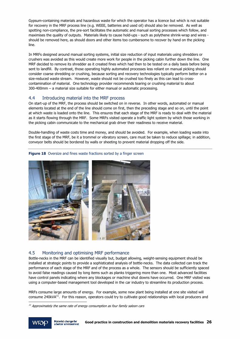
The initial automated pre-sort recovers soil and other fine material which account for a large proportion of the
input stream’s weight. The waste, which will have been compacted in the skips and other containers during
delivery, is also loosened up and aerated in the screening process. Two or more fractions are separated on the
basis of particle size, shape or weight. Fine waste, sometimes known as the ‘unders’ stream, falls through
(Figure 8), while oversized waste continues on the line. Both material streams may be first introduced onto a
hopper spreading the material on the conveyor belt, thereby facilitating subsequent sorting processes.
Figure 8 The unders fraction from a trommel

Good practice in construction and demolition materials recovery facilities 13
2.5 Material recovery from the undersized fraction The unders stream sometimes enters a picking cabin (see Section 2.6), but more often undergoes additional
automated processes: magnets remove small pieces of metal, while wind-shifters or density-separators
(sometimes called lights separation units or LSUs) blow or suck to recover small pieces of paper, plastic film and
wood. Until recently, this material - known as fluff or flock - was simply landfilled, but MRF operators now send it
for composting or convert it to RDF (refuse-derived fuel) (see Section 7.5). The cleaned-up soil and fine
aggregate remaining may undergo further processing. This material is typically used for land restoration
purposes.
2.6 The picking cabin The large fraction emerging from the pre-sort screen often passes under an overband magnet, which pulls off
small pieces of ferrous metal, and then approaches the picking cabin (Figure 9). Most plants still rely on manual
labour for recovering non-inert recyclates. Pickers pull off various types of rigid and film plastic (e.g. HDPE,
LDPE, PP, PET, and uPVC), non-ferrous metal (e.g. copper, lead, brass and aluminium), cables and wires, paper,
card and wood. The latter is frequently divided into A and B grades. Ferrous metal not removed by previous
magnets is also picked off. Each recovered material is dropped down chutes into separate bays located below
the picking shed, for onward movement. Any oversized objects or non-recyclables such as insulation foam,
polythene sheets, batteries and WEEE missed in the tipping area are also removed in the picking cabin. Glass
and textiles are sometimes also removed here. Most picking cabins have a ‘waste’ chute for material whose
recycling is uneconomic, such as polystyrene or contaminated items.
Figure 9 Picking station
Most of the material passing untouched through the picking cabin is aggregate – although in some facilities
manual pickers may even take off this material. An air-knife removes fine pieces of paper, plastic and wood from
the aggregate as the latter drops off the line. This flock, typically blown into a cage, was once landfilled but, as
described above, MRFs may now send it for composting or energy recovery at incinerators and combined heat
and power plants. The aggregate itself is crushed (perhaps using an ‘in-line jaw crusher’), sieved and washed
before being sold on for road-building and other uses.
2.7 Onward destinations for non-inert material recovered by MRFs Little further processing is performed at the MRF on the recovered materials, although wood is normally shredded
for ease of storage and transport. Any ferrous nails and screws embedded in the wood are recovered using
magnets incorporated in the shredder and are sold on for recycling.

Good practice in construction and demolition materials recovery facilities 14
Today almost all non-inert outputs from a C&D MRF can be recycled or reused in some way. Depending on the
material, the operator will either be paid or incur a cost for onward movement. All forms of ferrous and non-
ferrous metal can be entered into closed-loop recycling, as can paper, cardboard and a growing range of plastic
polymers. Recycling uPVC (often in the form of door and window frames) has traditionally been a problem, but a
number of take-back schemes are now in operation, and the material can now be closed-loop recycled.
High quality timber (often in the form of old wooden pallets) is variously known by MRF operators as ‘A grade
wood’, ‘clean wood’ or ‘white wood’ and commands a good price from re-processors who convert it to animal
bedding, panelboard, or burn it as a biomass fuel. Which of these outlets is used depends on the location of the
MRF; few panelboard makers operate in the south of England, so facilities based here tend not to use this option.
‘B wood’ such as treated or painted timber, chipboard and MDF is worth less but still has a value, again in
biomass burning. Lower grade wood may also be composted along with green waste (i.e. leaves, branches and
other vegetation) or used as a landfill cover if exemptions are applicable. One MRF is working with a waste
management company trialling the use of lower quality wood as a road surfacing matting on landfill sites, as
aggregates tend to sink into the waste. Whether this qualifies as recycling is debatable. A new process using
microwave technology to recycle MDF waste into new MDF is currently being trialled5. However whether this
would be suitable for re-processing treated, post-consumer MDF rather than factory offcuts is as yet unclear. In
most - if not all - cases the wood will be shredded prior to onward movement to reduce transport costs.
Recycling low grade plastic and paper is a problem for C&D MRFs as they tend to be contaminated with cement
and other building materials (Figure 10), particularly when collected with a mixed load.
Figure 10 Rigid plastic contaminated with cement
Sometimes the plastic can be sent to washing plants but this is unlikely to be cost-effective, thus materials such
as these are normally sent to landfill. However, as discussed in Section 7.5, the emergence of a network of
energy recovery facilities is providing a new outlet for low grade paper, wood and plastic: material previously
landfilled. Depending on where in the country the MRF is located – and hence the local landfill rates – the use of
energy from waste (EfW) facilities may be a more economic option, particularly as the cost of landfilling is rising
with the Landfill Tax escalator. In Scotland and parts of northern England, however, landfill gate fees are still
very low even with the rising tax, so the financial incentive to recycle low value materials or even to send them
more than a certain distance for energy recovery may not yet exist here. One MRF company suggested that the
cost of landfill in Scotland was lower because less waste was available and landfill operators were “fighting for
tonnage”.
Several companies are able to recycle plasterboard and gypsum-containing materials, and the sector is likely to
grow now that that material will be banned from non-hazardous landfills in England, Wales and Northern Ireland
(Section 3.8). The situation in Scotland is less clear as some MRF operators inform us that outlets are scarce in
Scotland, and transport costs to re-processors south of the border are prohibitive.
5This process was patented in 2004 by Microrelease Ltd, a subsidiary of Nviro Cleantech. More information is available at: http://www.nvirocleantech.com/our-portfolio/mdf-medium-density-fiber-recycling/

Good practice in construction and demolition materials recovery facilities 15
Glass is a less common output from C&D MRFs, but where cullet is recovered the material tends to be used in
aggregate applications, because closed-loop recycling requires colour separation of larger pieces of glass. As
discussed in Section 3.8, ceramic material from tiles presents a problem for MRFs in that this can contain
hazardous material, but some MRFs questioned revealed that this material was typically processed for use as an
aggregate in the same way as glass.
Figure 11 Some non-inert C&D WASTE materials recovered by MRFs
Top L to R: plastic film, rigid plastic.
Middle L to R: cardboard, ferrous metals and copper.
Bottom L to R: A grade wood, B grade wood.

Good practice in construction and demolition materials recovery facilities 16
CASE STUDY: MRF operators workshop
At a meeting in December 2008, organised by WRAP, a number of MRF operators were invited to
identify what they thought was ‘good practice’ in construction waste recovery. The following is a
summary of the outcomes.
� Advise the customer – the earlier the better All delegates agreed that it is important to advise the customer about site waste practices at the beginning of a
C&D project. The earlier this can be discussed, the better for both parties. One delegate kept an eye on
planning applications in the area, even to the extent of writing to the architect and offering help with the
planning application. This opens up opportunities to offer a greater range of services and to have a greater
influence on site waste management arrangements if successful, thus ensuring a better quality of input material.
This early involvement is still rare, however. Waste operators rarely get called in at the design stage of a project
and the introduction of Site Waste Management Plans (SWMPs) in April 2008 has had limited impact on this
situation.
Methods of advising the customer included:
� A DVD of waste and recycling services offered;
� Visits to the MRF;
� Offers to assist with SWMP;
� Offers of on-site waste management staff (only practical on larger projects or with the larger blue chip companies). It was noted amongst the delegates that there had been little uptake of this offer, possibly due
to the historic lack of trust in the waste management industry. As waste service suppliers become more
professional, however, the general trust of the industry is growing. Membership of the Environmental
Services Association’s Recycling Registration Service (RRS) was seen as an additional important step in this
direction, although the scheme is principally aimed at waste management companies handling and processing
municipal recyclables for export to overseas re-processors; and
� Pre-project meeting to assist in waste management planning.
Services offered to the customer must adapt to the changing waste composition as a project moves from
demolition through excavation, footings, build and fit-out.
� Data reporting Customer-specific, project-specific and material-specific recovery figures are increasingly requested by C&D
customers. In practical terms these are only achievable by visually checking every load and recording the
approximate mix of materials. An added benefit of this practice is the ability to alert customers to non-
compliance issues as soon as they occur. It is possible, with large contracts, to stockpile waste from one source,
empty the line, then run the line from the stockpile, although storage of material prior to processing can be an
issue. This would give a complete data set which is specific to one project, if only on a sampling basis. All data
should be weight-based (tonnes) rather than volumetric, such as the number of lifts of containers of specific
volumes. The weight of each load is then taken from the weighbridge records at the receiving MRF or transfer
station.
It was agreed amongst delegates that there should be no need to hide MRF performance data from the
customers, as has been widespread in the past, since good MRF results have a positive public relations value and
discourage the use of less responsible waste operators. Proactive companies which respond quickly to clients
needs have a competitive advantage.
� Requests to supply on-site mobile plant Mobile compaction plant is sometimes requested in order to minimise space requirements for waste containers on
site. It was agreed that this should be carefully considered because of the risk of misuse, particularly by filling
with heavy or unsuitable material, which may be hidden at the point of collection and which can damage the MRF
plant, and subsequent potential health and safety risks that may be present to MRF operatives. However, for
larger projects, on-site treatment plant (such as shredders, crushers and trommels) is sometimes requested and
this is provided.

Good practice in construction and demolition materials recovery facilities 17
� Control of feedstock and avoidance of unsuitable wastes The use of the waste contractor’s own fleet was preferred since this provides better control of the quality of
feedstock. Also it was felt that, if third party transport is used, the waste may be ‘skimmed’ of valuable
recyclates prior to delivery to the MRF. It was agreed that it is important to develop a good working relationship
with clients to encourage better communications and result in better control of the waste material.
� MRF size Although the larger the MRF, the greater is the opportunity for investment in processing equipment, MRF size is
largely controlled by the site location and the type of wastes available. The availability of land is an issue – MRF
operators always want more space, especially when stockpiling of recyclates is necessary.
� Processing and technology The general consensus amongst the delegates was that there needs to be a mixture of automation and manual
sorting in any process layout. One operator argued that “you cannot do away with the picking cabin manual
sorting process if you wish to obtain a high quality material output”.
Pre-sorting or ‘quality picking’ is vital at the tipping stage, to remove problem items such as mattresses, canisters,
and large plastic film, and to minimise the contamination of sensitive materials. Separate collection may be
better for some of these materials. Delegates present at the workshop did not use manual pre-sorting, primarily
for safety reasons, arguing that an experienced mechanical grab operator can identify and safely remove even
the smallest of unsuitable items from the tipping floor.
� Other comments � The use of large balers provides the opportunity for higher per tonne sales values of material outputs.
� It is important to design the sorting plant to be flexible and to permit adaptations to handle changing waste
composition. The use of purpose-built equipment to match one’s own waste types may be achieved by taking
off-the-shelf machines and modifying them.
� Good maintenance, both planned and preventative, is vital.
� An on-site engineer is valuable, but should be supplemented by local third party engineering service operators who are able to respond at short notice to emergencies.
� Do not attempt too much integration of recycling or re-processing facilities for non-inert materials within the
MRF. “Stick with what you are good at.” The exceptions to this are that consideration may be given to
installing on-site thermal treatment (EfW) plant, plastic and paper segregation, and size-reduction of rigid
plastics.
� Look after your employees The need to train and develop staff at all levels, in order to motivate and retain them, was universally agreed.
Currently, it was felt, there is too much reliance on “transient” and agency labour at floor level. The use of
financial incentive schemes, however, was not universal amongst MRF operators. One delegate paid a quarterly
bonus based on the value of the scrap metal sold. The bonus is lost when the value falls. Another operator was
working on a MRF-wide bonus scheme based on overall quality and throughput. Such schemes were said to stop
employees taking materials of value. Some driver bonus schemes are in place which reward (or penalise) the
drivers for good (or bad) control of waste collections.
Optimum flexibility of staff is achieved through training and the setting up of skills matrices so that, ideally,
everyone can do every job at the site.
Clearly, good working conditions were favoured including:
� Comfortable cabin conditions for manual pickers;
� All operations being carried out under cover; and
� The use of dust suppression such as odorised misting systems.
� Other ‘good practice’ Develop good relations with material processors and manufacturing organisations. Evidence suggests they will
maintain off-take in difficult times, if at all possible, in return for trusted quality.
Develop good relations with local residents; especially important in urban locations. This may be achieved by a
combination of such activities as secure/acoustic fencing, odour control, noise control, open days, community
talks and control of lorry movements.

Good practice in construction and demolition materials recovery facilities 18
3.0 Managing supplies This section explores some approaches by which MRF operators can manage suppliers of waste – and thus control the waste itself. 3.1 Meeting the supplier’s requirements MRF operators should be prepared to offer C&D customers a wide range of services. Until recently, customers
were merely interested in a competitive skip hire rate and compliance with environmental regulations. Today,
many C&D customers - especially the larger ones - expect a more comprehensive service from their waste
management contractors including project-specific and material-specific recovery rates and breakdowns of the
fate of all waste processed. Indeed, some C&D contractors or their clients now audit waste management
systems. This occurs both at the tendering phase, where environmental and data reporting issues may influence
the award of a waste management contract, or during the construction project itself, to ensure compliance with
promised performance. Whilst only top-level data are required by Site Waste Management Plans, more detailed
reporting as outlined above can be inputted into resource efficiency tools such as SMARTWaste Plan (developed
by BRE) and WRAP’s NetWaste Tool. Many of the MRF companies visited for this study were asked by their
customers to provide this level of detail – although the accuracy of the figures supplied has been called into
question by some. In extreme cases, MRFs were prepared to run client’s waste separately through the plant and
weigh each output stream in order to gain accurate information on material-specific recovery rates. WRAP
developed, trialled and launched the Site Specific Waste Assessment Tool (SSWAT) a new measurement method
for MRF operators to calculate consignment-specific recovery rates. This is freely available on the WRAP website
under www.wrap.org.uk/constructionmrf.
3.2 ‘Know your waste’ This piece of advice was frequently offered by informants to the study. Construction and demolition waste is
diverse. The material varies in density, shape, stickiness, water content, chemical composition and many other
properties each influencing the recovery processes. To maximise recovery, C&D MRF operators must be aware of
exactly what is brought onto the site. This is straightforward where a regular business relationship exists with
the constructor and where the MRF operator’s own drivers are used and are fully trained in waste acceptance
criteria.
Additional scrutiny of incoming waste from third-party tippers (such as independent skip hire companies) is
required, as this may result in unfamiliar material entering the site. Where such waste is accepted, often from
local companies with whom the MRF operator has a long business relationship, skips should be tipped
immediately and contents scrutinised for non-compliance with the site licence or discrepancies with the Waste
Transfer Note.
The process of getting to know waste should start early in the supply chain. MRF operators could consider
scrutinising building projects at the tendering stage and even at the planning stages. New C&D sites should be
visited to assess likely waste materials – and to ascertain the likely sequence in which different waste types will
arise. As discussed above, various tools and methodologies, such as the NetWaste Tool and the SMARTWaste
Plan have been developed to predict the type and volume of waste materials likely to arise at each phase of a
building project6.
Several MRF managers second their own staff to larger C&D sites to advise clients on waste and recycling issues,
to oversee disposal into skips, and to prepare waste for optimal sorting at the MRF. Weight analyses of skips are
sometimes performed at the C&D site. These services may either be offered free or along with equipment hire as
part of a total waste management package.
The MRF operator should prepare for waste arisings to vary with the season. One informant estimates that levels
of waste fluctuate over a 30% range through the year. Peak periods include spring and summer; C&D activity is
reduced in winter and this is a good time to implement significant changes to MRF systems or equipment.
3.3 Source-segregation vs. mixing waste Source-segregation of C&D waste prior to disposal is growing in the UK. Not only does this reduce waste disposal
costs and benefit the environment, but segregation schemes often result in a more orderly site, safer working
6 http://www.wrap.org.uk/construction/tools_and_guidance/index.html

Good practice in construction and demolition materials recovery facilities 19
conditions, and an enhanced company reputation7. Materials typically segregated include wood, plasterboard,
brick and rubble. Skips may also be provided for mixed light recyclables such as paper, card and plastic and for
rigid plastics such as uPVC window and door frames. Where material-dedicated skips are used properly the
recovery process is made easier, and costs to both customer and MRF operator are accordingly reduced. For
example, one MRF operator charges waste producers a flat transport fee of £65 with an additional £57 per tonne
disposal cost for mixed 8-yard skips. For source-segregated skips, the disposal costs charged to customer are far
lower. For higher value materials (e.g. scrap metal) the disposal cost is negative; in other words, the MRF will
effectively offer the producer a rebate on the £65 per skip transport cost. The same MRF operator reports that
the average weight of waste in a mixed 8-yard skip is around 4.5 tonnes, while source-segregated materials
weigh on average 1.5 tonnes. Clearly, waste producers hiring skips from this company benefit enormously by
avoiding the use of mixed waste skips.
Figure 12 A mixed skip in London
In urban settings or in high-rise projects, where space is limited, it may be practical only to provide one skip
(Figure 12). However, one MRF operator reports that even in a one-house-build project, source segregation is
still economic. In confined situations alternative container solutions such as builders’ bags8 or wheelie-bins could
be considered. In this system, a simple colour coding scheme, backed up by icon labels, should be applied to
optimise waste segregation and help with communication with the receiving WMC and staff at collection point.
Policing single-material skips to prevent contamination is vital because the latter leads to increased expense for
C&D customers charged the higher price of a mixed skip. One MRF company informs us that if contamination of
a source-segregated skip exceeds 5% they give the waste producer a verbal warning (accompanied by
supporting photographic evidence). If the non-conformities continue, the higher costs are levied. The same MRF
reports that of the roughly 200 containers processed daily, around six present ‘quality issues’.
It is not clear whether anecdotes such as these were related from a vested interest, in that MRF operators could
lose out financially if most of their customers switched to source-segregation. Several interviewees commented:
“We are the waste experts so leave the sorting to us.”
7TRADA Technology. 2004. Research information. Saving on waste disposal – through waste segregation in construction. A timber waste management case study – Construction.
8 WRAP has recently commissioned trials into the use of using builders’ bags for collection of packaging waste. The bags are
transported to the MRF and removed separately.

Good practice in construction and demolition materials recovery facilities 20
3.4 Customer education and training MRF operators themselves benefit when they educate and train their waste suppliers and other stakeholders in
the proper way to present material. For example, the financial (and environmental) cost of not using source-
segregated skips should be made clear to the C&D client. Several MRFs interviewed encourage C&D customers
to visit their site in order to understand the requirements of the material recovery processes. They also hold
workshops or give talks in the community, and a few have invested in on-site education centres, and training or
marketing suites. In one case, the MRF operator nominates a ‘green champion’ on each construction site and
rewards good quality waste management with a monthly box of chocolates or crate of beer. It was reported that
these apparently simple measures could increase C&D site waste recovery rates by up to 25%. Unfortunately, in
other cases where the ‘recycling culture’ is not embedded in the C&D workforce, even financial incentives may
not have the desired effect. For example, an interviewee described how, despite the potential to personally gain
up to £400 per week for excluding non-inert materials from aggregates-dedicated skips, one foreman was still
failing to achieve this. Another MRF operator highlighted the case of a single large construction customer who
failed to police source-segregated skips properly at fourteen of its fifteen sites.
3.5 Reuse and remanufacture Strictly speaking, once something has been discarded it should be regarded and treated as waste. However, in
practice, if an item can be directly reused in its current form (without re-processing) with minimal risk to human
health or the environment then scope for reuse or remanufacture exists. The MRF operator should thus use
common sense and still follow proper duty of care.
Where possible, opportunities for reuse and remanufacture should be assessed at the C&D site, particularly on
large demolition projects. Networks are now well established9 for many types of end-of-life products including
material from C&D projects. Once waste arrives at a MRF, objects can also sometimes be recovered for reuse or
salvage as long as site safety is not comprised. MRFs report salvage of items such as Belfast sinks, fireplaces,
culverts and walling stone. It may sometimes be possible to donate items to charities10. The most appropriate
stage at which to extract materials is during the pre-sort where the mechanical grab can pick out materials. For
obvious reasons employees should avoid rummaging by hand through piles of tipped waste. A dedicated,
covered bay for salvage should be assigned away from machinery or moving vehicles. Certain items may not be
suitable for reuse or remanufacture; for example, chairs may be weak and could collapse exposing the MRF
operator to litigation. Old fire-doors and other safety equipment cannot be reused as such for similar reasons.
3.6 Generating business MRF operators suggested ways to sustain and grow business in an unstable economic climate. Although repeat
business may comprise a significant proportion of a MRF’s turnover - 70% in one case – MRFs are increasingly
required to take a more active approach and perhaps look further afield for custom.
Interviewees discussed new ways to generate business such as employing sales people, re-branding the company
image, and creating a high quality website. An increasing number of MRF operators are signing up to The
Construction Commitments: Halving Waste to Landfill which sends a positive message to would-be customers that
the waste company is not a ‘cowboy’, but is serious with regard to responsible waste recovery.
An obvious step is setting the cost of using a MRF at a level competitive with other MRFs and alternative disposal
routes including landfill. This cost may simply be in the form of a gate fee, or subsumed within the skip hire
price.
In return for exclusive access to waste, some MRFs in competitive environments offer their customers loyalty
discounts. With the provisos outlined above, MRF operators should aim to accept as wide a range of wastes as
possible under their licence, but equally be prepared to walk away from a job when necessary. At all times, the
MRF has to be able to control and manage the waste effectively.
9 For more information visit www.remanufacturing.org.uk - the website of the Defra-funded Centre for Remanufacturing and Reuse.
10 In England & Wales, the Environment Agency has published a list of waste exemptions for storage and handling materials due for recovery, and even where an exemption does not currently exist, the EA may sometimes apply a ‘low risk ‘ position – for example, on furniture or clothing. More information is available at: http://www.environment-agency.gov.uk/business/topics/waste/32080.aspx.

Good practice in construction and demolition materials recovery facilities 21
MRF operators should seek a wide range of C&D clients, but a few reveal that business was being sustained
during economic downturn thanks to relationships with a few large social housing firms. Public sector
construction is perhaps more immune to poor economic conditions than is the private sector.
In rural or isolated areas of the UK where transport costs become a limiting factor, some MRF operators use
drawbar trailers which can fit up to six skips on the same vehicle. This increases the geographic area that can be
economically served. Similarly, drawbar trailers can increase the range that outputs can be transported for
re-processing. For example, one MRF operator will use drawbar trailers when needing to move recovered wood
further than 20 miles. Many waste management companies establish satellite transfer cabins to consolidate
waste from a wide area before onward transport to the MRF. As a last resort, MRF operators can also use the
services of fully-vetted third party skip companies to further their reach. A number of the larger MRF companies
visited have expanded by acquiring skip hire companies in their region allowing them to increase coverage while
remaining in control of their waste.
Transparency in the onward destination, and the sale price, of output materials can also help MRFs attract
business, especially from higher profile customers such as blue-chip construction firms. If economically viable for
the MRF, the output revenues may be shared with customers although this tends to be more common in
municipal MRFs where the outputs are generally of a higher value. One MRF, which accepted household
recyclates as well as C&D arisings, offered its Local Authority customers rebates linked to materials prices
published on websites such as www.letsrecyle.com. The same company also offered a rebate based on metal
sales to a nationwide retailer whose waste it processed. Openness in terms of other MRF expenses such as
transport and management fees is also important.
3.7 Recovery rate measurement and reporting All the MRFs visited provide waste producers with average site-wide material recovery rates calculated on a
monthly basis. However, new customers can be attracted by offering, at little or no cost, data on the recovery
rates for each skip load tipped. One MRF questioned revealed that on request, and on a sampling basis only,
they would tip the contents of several skips onto the MRF floor, segregate each waste material manually, and
individually weigh the fractions in order to provide a breakdown. The new SSWAT can provide consistency in
measuring and reporting particularly with mixed waste consignments. Clearly this process is time-consuming but,
according to the MRF, is worth doing to provide the customer with a snapshot of their waste profile. This type of
service is of particular value to larger waste producers in England because for any project exceeding £300,000 in
value a Site Waste Management Plan has been a legal requirement since April 2008. SWMPs are still voluntary in
Wales, Scotland and Northern Ireland but may become mandatory in the near future.
For the same reason, MRF operators should look at implementing formal management systems such as ISO 9001
(quality management), ISO 14001 (environmental management) and OHSAS 18001 (health and safety). These
internationally-recognised standards are increasingly called for when tendering for work with larger waste
producers, particularly those in the public sector. However, putting these systems into place is time-consuming,
and operators need confidence that customers will require them. Several larger MRF operators questioned
nevertheless saw value in the systems for improving their own day-to-day activities, especially as their
management structures became larger and more complex.
Reported recovery rates ranged from 75% to 98%. A significant barrier to maximising landfill diversion was a
lack of storage space – particularly a problem during the economic downturn where many MRFs are being forced
to landfill certain output materials rather than hold out for a good market price. Several operators wanted to
expand the size of their facility but were facing planning constraints. Another barrier to 100% diversion cited by
informants was the lack of nearby EfW plants to accept the residual waste, and even when the latter were
available, MRFs struggled to provide fuel of sufficiently acceptable quality. A lack of funds for capital expenditure
on new equipment – especially in an economic downturn - was also cited as a barrier to maximising recovery
rates. Even with its rising cost, many MRF operators still feel forced to dispose of significant volumes of material
to landfill.
3.8 Problem materials Certain materials arising from C&D activity pose particular difficulties for MRF operators, and justify careful visual
inspection of every incoming load, regardless of origin. Special processes and licences are required for managing
hazardous materials including WEEE, asbestos, gas bottles, clinical waste, and incineration residues (Figure 13).

Good practice in construction and demolition materials recovery facilities 22
Figure 13 Storage area for hazardous waste
Plasterboard and other gypsum-containing material frequently arise from C&D projects and, although not classed
as hazardous (unless contaminated with hazardous material), are a particular issue for the MRF operator. Proper
disposal has in recent years caused some confusion in England and Wales. With the April 2009 revision to the
Environment Agency position on waste plasterboard management, waste managers will now be required to
recycle all gypsum materials or send it to dedicated mono-cells at landfills where it cannot mix with biodegradable
waste. Up until the April 2009 revision, small concentrations of the material were permitted to be disposed in
ordinary landfills – the ‘10% rule’. Any gypsum-containing material delivered at the MRF must now be kept
separate from other waste materials to prevent incorrect disposal, and it is in the interest of the MRF operator to
require suppliers to collect gypsum waste separately on site. In England, several companies will recycle gypsum-
based products, and plasterboard take-back schemes are operated UK-wide by manufacturers British Gypsum,
Knauf Drywall and Lafarge Plasterboard. The ‘10% rule’ still applies in Scotland, possibly due to a lack of outlets
for plasterboard as reported by one Scottish MRF operator. MRFs in Northern Ireland apparently have more
options since, according to one interviewee, a gypsum recycling company is present in the Province and several
more are located south of the border in the Republic of Ireland. As in England and Wales, Northern Ireland has
banned disposal of gypsum to non-hazardous landfill as of April 2009. Appendix 3 has further information on
waste gypsum management. Apart from these regulatory issues, plasterboard is in itself an awkward material in
that it easily breaks up releasing dust in the air and, in wet weather, forming a messy ‘glue’.
Where doubt exists as to the nature of a material, MRF operators should err on the side of caution as they will
need to prove to regulatory authorities that they are compliant with the stipulations of their site licence. If any
non-conforming material does enter the MRF then the process must immediately be halted and the offending
waste items removed, securely stored and passed on for appropriate processing. A record of the incident should
be kept.
As discussed in Section 2.3, various non-hazardous materials also disrupt the smooth operation of a C&D MRF.
Mattresses are a particular problem as their wiring can jam up machinery, as does polythene shrink-wrap, loose
baling wire, and unravelling video cassette tape (Figure 14). These materials also wrap around recyclables
obstructing effective manual or automatic recovery. When such articles enter the MRF, operators are forced to
stop the line and resort to wire cutters and utility knives to remove the blockages - itself a hazardous process.

Good practice in construction and demolition materials recovery facilities 23
Figure 14 Video tape wrapped around trommel
Most, if not all, of the MRFs visited accept a proportion of commercial and industrial (C&I) waste such as office
canteen waste and old packaging. In rural areas, plastic film associated with the food growing and processing
industries can be a common waste stream and causes problems since packaging contaminated with food,
especially meat products, needs to be treated separately under animal by-products regulations. The presence of
biodegradable polymers in mixed plastic bales was also mentioned as a problem because the latter fall apart if
stored for too long. Other problem materials include ceramic tiles (particularly fire-resistant ones which may
contain hazardous ingredients), wet plaster bags and insulation (polystyrene and phenolic foams).
Of course, any material (e.g. low grade mixed plastic or mixed paper) whose recovery is not economic is also by
definition a problem for MRFs, especially if no EfW plants are close by. Such materials are still being sent to
landfill in substantial quantities.

Good practice in construction and demolition materials recovery facilities 24
4.0 Material flows
This section examines how at every stage MRF operators can process C&D waste to optimise material recovery and diversion from landfill.
4.1 At the C&D site As discussed in Section 3.2, MRF operators should work closely with waste producers and where possible visit
C&D projects in advance. Once the waste begins to arise, a series of checks should be performed verifying that
material placed by waste producers into skips (or other containers) conforms to details entered on
documentation. For example, consignments handled by one MRF are checked three times: first by the C&D
customer, then by the skip-truck driver, and finally by personnel at the MRF itself. Any non-conformities can
quickly be identified and information fed back to the customer for corrective action.
4.2 At the weighbridge Although Duty of Care rules require both the waste producer and receiver to understand the type and quantity of
material being transported, in practice the weighbridge is often the first opportunity the operator has to gain a
full understanding of the material arriving on the site (Figure 15). This is because waste producers from C&D
sites frequently mark the consignment as ‘general waste’ – EWC code 17.09.04. In many MRFs, site managers
work in the same location as the weighbridge operator to have a direct overview of all incoming material.
Regular communication, typically with two-way radios, between the weighbridge and personnel working in the
MRF itself is crucial. Two-way radios should be provided to all vehicle operators for safety and general
communication. Weighbridge staff who are given Waste Transfer Notes by skip drivers can inform colleagues in
the waste receiving bay about incoming waste, and in return can be quickly alerted should non-conforming waste
be tipped.
Figure 15 Skip-truck drives onto a MRF weighbridge
4.3 Initial management of waste Before any skip-load is tipped, the MRF operator should assess whether or not the waste actually needs to pass
through the MRF sorting line. Well-managed single material consignments from trusted sources, for example
skips of wood or rubble, can be directly off-loaded in areas of the MRF where recovered material of this type is
stored for further processing. Several MRFs visited had designated zones for ‘white van waste’, i.e. arisings from
local builders which can be directly hand-sorted, thus by-passing the MRF. One plant directed any skip weighing
more than 6 tonnes to a hardcore tipping area.
The mechanical grab operator is critical in ensuring a steady, manageable flow of waste into the MRF; the grab
also breaks apart any bags containing waste. Once a skip or other container is tipped, the contents should be
examined and pre-sorted, and if necessary any bulky objects which can cause blockages later on should be
removed (Figure 16). Personnel should not work on the bay floor in front of the grab as this is dangerous.
However, in one MRF visited, a safety protocol was strictly adhered to whereby a pre-sort operator was able to

Good practice in construction and demolition materials recovery facilities 25
safely remove, or identify for mechanical removal, unsuitable items in one tipping bay while the mechanical grab
was loading waste from another bay onto the sorting line.
Figure 16 Mechanical grab driver pre-sorts C&D waste
Any non-conformities or hazardous contaminants of the type discussed in Section 3.8 should be immediately
reported to the weighbridge and extra charges added to invoices when appropriate. Digital photographs should
be taken, and if possible sites should operate CCTV, to gather corroborating evidence (Figure 17).
Figure 17 CCTV cameras over MRF weighbridge
Good practice in construction and demolition materials recovery facilities 26
Gypsum-containing materials and hazardous waste for which the operator has a licence but which is not suitable
for recovery in the MRF process line (e.g. WEEE, batteries and used oil) should also be removed. As well as
spotting non-compliance, the pre-sort facilitates the automatic and manual sorting processes which follow, and
maximises the quality of outputs. Materials likely to cause hold-ups - such as polythene shrink-wrap and wires -
should be removed here, as should doors and other items too cumbersome to recover by hand on the picking
line.
In MRFs designed around manual sorting systems, initial size reduction of input materials using shredders or
crushers was avoided as this would create more work for people in the picking cabin further down the line. One
MRF decided to remove its shredder as it created fines which had then to be tested on a daily basis before being
sent to landfill. By contrast, those operating highly automated processes less reliant on manual picking should
consider coarse shredding or crushing, because sorting and recovery technologies typically perform better on a
size-reduced waste stream. However, waste should not be crushed too finely as this can lead to cross-
contamination of material. One technology provider recommends tearing or crushing material to about
300-400mm – a material size suitable for either manual or automatic processing.
4.4 Introducing material into the MRF process On start-up of the MRF, the process should be switched on in reverse. In other words, automated or manual
elements located at the end of the line should come on first, then the preceding stage and so on, until the point
at which waste is loaded onto the line. This ensures that each stage of the MRF is ready to deal with the material
as it starts flowing through the MRF. Some MRFs visited operate a traffic light system by which those working in
the picking cabin communicate to the mechanical grab driver their readiness to receive material.
Double-handling of waste costs time and money, and should be avoided. For example, when loading waste into
the first stage of the MRF, be it a trommel or vibratory screen, care must be taken to reduce spillage; in addition,
conveyor belts should be bordered by walls or sheeting to prevent material dropping off the side.
Figure 18 Oversize and fines waste fractions sorted by a finger screen
4.5 Monitoring and optimising MRF performance Bottle-necks in the MRF can be identified visually but, budget allowing, weight-sensing equipment should be
installed at strategic points to provide a sophisticated analysis of bottle-necks. The data collected can track the
performance of each stage of the MRF and of the process as a whole. The sensors should be sufficiently spaced
to avoid false readings caused by long items such as planks triggering more than one. Most advanced facilities
have control panels indicating where any blockages or machine shut downs have occurred. One MRF visited was
using a computer-based management tool developed in the car industry to streamline its production process.
MRFs consume large amounts of energy. For example, some new plant being installed at one site visited will
consume 240kVA11. For this reason, operators could try to cultivate good relationships with local producers and
11 Approximately the same rate of energy consumption as four family saloon cars

Good practice in construction and demolition materials recovery facilities 27
where possible seek supply deals, especially with local EfW plants. Several MRF operators are planning their own
on-site power generation systems, such as gasification, as a way of treating non-recyclable waste and saving on
energy bills. Power factor correction is also worth considering. Capacitors convert out-of-phase electricity
consumption into single phase reducing the effort required to drive the electricity around the plant. The choice of
equipment determines energy use: for example, conveyor belts are a more energy-efficient way to transport
material than compressed air systems.

Good practice in construction and demolition materials recovery facilities 28
5.0 People
Never underestimate the human factor. Even highly-automated facilities need a manual element to optimise the quality of outputs. This section suggests how to get the best out of site-based employees.
5.1 Hiring staff Most MRFs visited emphasised the importance of hand-sorting in ensuring quality of the final product. Although
machines are now able to distinguish between most types of material, humans are still more effective at
extracting most objects from the waste flow. Even highly automated MRFs rely on manual picking for the
recovery of awkward materials, such as larger metal objects or non-ferrous items like copper wire.
The use of agency staff or short term contracts was common, offering flexibility to the operator as material flow
fluctuates. As discussed in Section 3.2, waste volumes can drop by 30% or more during winter. However, MRF
operators should retain core staff to train and motivate temporary workers. These permanent employees should
be trained to operate all equipment in the MRF in case of staff absence. Most MRF operators implemented a
relatively flat management structure to maintain close control of the flows of material in the plant. It is
recommended that each member of staff is trained to operate all machinery to offer flexibility and cover
employee absences.
When recruiting senior staff, MRF operators should consider looking outside the waste industry. MRFs resemble
production lines, so a manufacturing expert might get more out of staff and equipment than could someone from
a waste background. The net should also be cast wide when seeking experts in health and safety. One MRF
operator had hired someone unfamiliar to the waste management industry in order to bring a fresh perspective to
potential hazards.
Figure 19 Loading shovel in action at a C&D MRF
5.2 Motivating and training staff Keeping picking staff motivated in what can be a mundane job is vital for maximising material recovery. MRF
operators should take trouble to ensure the working environment is well-lit, comfortable and safe (Figure 20).
The installation of dust extractors, and air conditioning and heating units is recommended. Many MRFs had
sound systems to keep workers entertained, and a few provide excellent quality canteens and changing rooms.
Regular breaks are also important, and where appropriate staff should be rotated between tasks.
Although exceptions to the rule, several MRF operators visited for the study used financial incentives to motivate
picking staff and other employees such as drivers and maintenance workers. One plant offered pickers a £4
bonus for every tonne of wood recovered, while another linked the bonuses of all employees to the total value of
recovered output materials. One site paid workers a small Christmas bonus based on the annual recovery of non-

Good practice in construction and demolition materials recovery facilities 29
ferrous metals. Some sites penalise drivers who accept non-conforming waste consignments from C&D sites.
The schemes should be designed so that recent recruits cannot earn more than more established employees as
this can be divisive. One approach may be to reward loyalty in the picking cabin by moving pickers from lower to
higher value output materials, linking pay to the respective output revenues. The schemes should also be
managed so that employees do not simply ‘chase their bonus’ to the detriment of fulfilling other key aspects of
their job such as equipment maintenance. It was suggested that materials-related bonus schemes could be
unfair since prices for, and tonnages of, certain materials could not be guaranteed.
Many MRF operators report good results from investing in staff training; one received funding from the local
Learning and Skills Council. Another stressed how import it is that all staff are aware of the financial implications
of making mistakes with waste, and ran ‘toolbox talks’ on new equipment and output quality control.
Figure 20 A picking cabin
5.3 Monitoring staff performance The other side of the coin is ensuring pickers - and other employees - are working efficiently and safely, since
labour is normally the largest running cost for a MRF. CCTV systems in picking cabins and in-vehicle tracking
devices are widely installed to monitor staff activity. These trackers have sometimes enabled the recovery of
stolen trucks. Practice shows that although initially unhappy to accept these measures, skip-truck drivers tend to
get used to them. As mentioned elsewhere, managers must discourage employees from picking items out of the
waste flow for personal use. This activity, known as totting, can be dangerous and reduces process efficiency;
workers will also miss recoverable materials.

Good practice in construction and demolition materials recovery facilities 30
CASE STUDY: Staff motivation via incentive schemes
Regardless of the degree of automation in the materials sorting process, the MRF managers
interviewed in the study were unanimous on the need to maintain the highest levels of skills and
motivation amongst the employees on the line.
Figure 21 The picking staff at Ahern Waste Management benefit from a performance-related bonus scheme
Maintaining high morale is particularly challenging in the C&D MRF environment where much of the work is
repetitive and can also be both noisy and dirty. Some companies run bonus-related incentive schemes for some
or all of their employees on the site and including the drivers. Successful schemes need to be related to the
quality of the work carried out (assuming satisfactory throughput rates are achieved), should be targeted at
individuals or small groups and be paid as near as is practical to the day or week in which the performance
occurred.
Within our study, however, the use of financial incentives for employees was the exception rather than the rule,
and, where such schemes were in place, they were not site-wide. An example of the latter is Ahern Waste
Management in West Thurrock, Essex (Figure 21) where a bonus is paid to staff engaged in manual picking and
sorting operations only. Here, a bonus is paid based on the overall recycling percentage of the MRF.
The majority of operators, however, insisted that good basic pay levels and the provision of optimum working
conditions, backed up by close supervision and strong management, was the best formula for motivating and
retaining skilled staff.
The following sets out some specific examples, other than Ahern, where bonus-related incentive schemes were
applied:
� Any employee’s basic wage might be increased on the basis of length of service in their first five years of
employment with the company, or against a skills matrix which would reward their proven adoption of
additional skills and expertise. This system has the advantage of increasing the flexibility of the workforce to
cater for changes in the quantities or mix of materials received and to maintain throughput during times of
sickness and holidays.
� Drivers of waste collection vehicles might get a bonus for each day in which they bring in an agreed number
of well managed loads to the site, but would get that bonus reduced for the day if they allow one skip to
enter carrying undesirable or non-contracted materials or if they are found to have picked up contaminated
waste which is meant to be site-segregated. Errors such as this will be recorded either by cameras at the
receiving weighbridge or by the pre-sorting operator at the point at which the waste is tipped.
� Manual picking operators were mostly found to be on the minimum wage. However, their work is often vital
to achieving the quality and quantity of recovered materials which are critical to the commercial success of

Good practice in construction and demolition materials recovery facilities 31
the site. Regular inspections by the picking supervisor of the quality of materials sorted into each bay could
be the basis of such a scheme and a bonus paid to the whole picking team. If poor quality of sorting happens
then the bonus is reduced. Team-work may be encouraged by such group bonuses, with peer pressure likely
to be applied to poor performing members. In this case, as indeed with all such schemes, close supervision is
vital to ensure that it does not have a negative effect on motivation due to circumstances which may be
outside the team’s control.
� A site-wide scheme based on a ‘balanced scorecard’ approach was also raised. Such a scheme is designed to reward all employees on a team basis in which everyone works together to increase a bonus pot. The
scheme involves allocating points to each key performance indicator (KPI) for the site, such as tonnage
processed, overall efficiency, percentage recovered, segregated and cleaned waste, and plant downtime.
Each KPI point score is then weighted according to its influence on the commercial success of the site to
arrive at a targeted points level, and a bonus is paid if the target is surpassed.
� Site-wide, the importance of regular management and sales meetings was evident, with all performance
statistics for the site openly displayed, and with everyone knowing what level of performance is needed for
the site to break even. Indeed, any individual schemes might be over-written by either a ‘top-up’ bonus in
any week in which the site meets or exceeds its target, or by a minimum performance level below which no
bonuses are paid.

Good practice in construction and demolition materials recovery facilities 32
6.0 Equipment and technology
Installing the right equipment at a C&D MRF is crucial. This section outlines issues to consider when choosing technologies, and assesses the relative merits of some important pieces of kit. 6.1 Limits to automation The level of automation in the MRFs visited varied markedly. In one case, handpicking had been reduced to an
absolute minimum in favour of machines recovering specific materials. The main advantage of automation is that
it can substantially boost a MRF’s sorting capacity and recovery rate. For example, after investing in a new
vibratory screen, one site’s average recovery rate increased from 70% to 85%. Machines also offer savings in
terms of labour cost and can reduce the risk of accidents inherent in manual sorting.
One MRF operator reported that many larger customers are becoming more interested in, and knowledgeable
about, the waste they are producing, and particularly its value. For this reason, the character of the waste
coming into MRFs is starting to change with easy-to-recycle valuable items such as metal often already
recovered, while harder to separate or lower value materials make up an increasing proportion of the skip’s
contents (Figure 22). MRF operators must be able to adapt their processes accordingly.
Figure 22 A typical load of mixed C&D waste
Various sorting equipment is now available recovering material on the basis of size, mass and other physical and
chemical properties. As one contributor says, “MRF operators must keep abreast of new technology
developments – continual improvement is vital to stay profitable.” Senior managers are well-advised to monitor
innovations in this fast-moving sector both in the UK and abroad. Modularity is important; MRF operators should
be able to ‘bolt on’ equipment as necessary – for example, when the market value of a specific output material
justifies it.
Automation is never perfect due to the sheer variability of waste, and the unpredictable way in which it responds
to sorting techniques. For example, the orientation of an item with respect to a jet of air in a wind-shifter may
determine whether or not it is recovered. As stressed above, some form of manual intervention is always
required to optimise output quality. Buying, installing and maintaining machinery is expensive; for example, a
vibratory screen can cost around £300,000, almost twice the price of a trommel with a similar throughput
capacity. Improvements in recovery efficiencies are also ever more difficult to achieve. One technology provider
reports that equipment with sorting accuracies of, say, 80% may cost four times more than equipment with 70%
accuracy.
MRF operators considering upgrading equipment must be confident of a rapid return of their investment. The
market for a particular output must justify the investment. The manager of one MRF visited was relieved not to
have installed an eddy current separator for recovering aluminium when the price for this metal slumped recently.
Another MRF had recently put in equipment for extracting plastic film from the waste stream and benefited both

Good practice in construction and demolition materials recovery facilities 33
from increased revenue from material sales and from reduced landfill costs. A third MRF considered spending
£250,000 in a machine to convert expanded polystyrene into condensed briquettes, but found that the high
transport costs for polystyrene foam would outweigh any revenues from the investment.
Where practical, sorting equipment should be kept mobile in case the plant layout needs reconfiguring. MRF
operators should aim to buy kit purpose-built for the specific facility and the type of waste likely to arise.
Alternatively they should be prepared to modify off-the-shelf machines.
Many of the more advanced technologies are more effective with size-reduced waste. For example, one highly
automated facility starts by crushing all C&D waste to 50mm maximum size. Shredding material more finely than
this should be avoided because (as discussed in Section 2.3) size-reduction hampers any handpicking – and leads
to unnecessary cross-contamination of waste.
6.2 Initial screening equipment Even basic MRFs usually invest in up-front pre-sort equipment. The choice of technology is vital. Up-front
screening of waste serves several purposes: soils and other fines not easily sorted by hand are removed
mechanically, the weight of material is reduced, and compacted waste is loosened up and aerated. A range of
equipment is available to perform these tasks.
6.2.1 Trommels Trommels of varying sizes are perhaps the most commonly used. They consist of a rotating cylinder set at an
angle with holes of a fixed diameter (Figure ). Small matter falls through the holes, while larger fraction
continues onto an onward conveyor belt. Some trommels have split screens – i.e. two sets of holes with different
diameters - so that more than one unders fraction can be sieved out. Trommels are tried and tested, space-
efficient with a relatively large screening area, simple to use, and have a high throughput and hence process
waste quickly. However, the fast process rate can cause problems for manual sorters further down the line; as
always, a trade-off exists between speed and accuracy of processing.
Figure 23 Under a trommel
One problem with trommels is that their tumbling action can cause plastic shrink-wrap or wires to coil around the
waste. This snaking or ‘sausaging’ effect hampers subsequent sorting processes. Another issue is that large
objects such as boards or carpets can block the holes. Such larger items should either be shredded in advance or
removed altogether from the input flow. Trommels like other automated equipment are noisy when running
although some are fitted with a neoprene liner which reduces sound (Figure 24).

Good practice in construction and demolition materials recovery facilities 34
Figure 244 Close-up on holes in trommel showing neoprene lining
Trommels can easily be damaged by heavy rubble which is lifted and then dropped by the trommel’s rotating
motion so are best suited for screening smaller, lighter non-inert materials. Damp soil is a problem for trommels
as it packs to the side of the screen and its weight is sometimes too much for the trommel’s motor to cope with.
Costs of the trommel depend on size – one MRF operator had spent £200,000 on a new machine.
6.2.2 Vibratory screens Various forms of vibratory screen are used instead of, or in addition to, trommels. They typically consist of a
series of tapered levels which are angled down. These levels shake vigorously, simultaneously sieving out the
fines and moving it down the slope. Both waste fractions are metered evenly onto onward belts facilitating
further segregation manually or automatically. One MRF operator pointed out that the teeth often snap off
contaminating both the overs and unders waste fractions, although another argued that certain designs are
superior to others, in that the sorting teeth are angled so as not to snag on waste.
Figure 25 Finger screen
The platforms of vibratory screens shake material only a few centimetres in the air, so are less prone to damage
by falling heavy waste. This equipment is also less vulnerable than trommels to ‘sausaging’ waste and blockages,
but as with disk screens (see Section 6.2.3 below), smaller waste may ride on larger items. Vibratory screens
also take up more floor space than do trommels. For this reason, some MRF operators suggest that vibratory
screens are appropriate for secondary screening of aggregates rather than for up-front segregation of mixed C&D
waste. An additional drawback of vibratory screens is their reduced capacity compared with disk screens or
trommels, but this may not be a problem as manual pickers can be overwhelmed if throughput is too high.

Good practice in construction and demolition materials recovery facilities 35
During wet months, the holes in screens sorting fine material – typically material less than 12mm in dimension –
can be blocked by mud. This problem is inherent in trommels and standard vibratory screens. Flexible screens
have been installed in some MRFs to tackle the issue (Figure ). They work by tensioning and rapidly releasing a
screening deck made from a flexible material. Waste objects are flipped in the air at accelerations approaching
50G and the screen’s holes are kept clear. The holes also change shape during the process again helping shift
blockages.
Figure 26 Flexible screen
6.2.3 Disk screens and star screens Disk screens or star screens are sometimes used for up-front screening either with, or instead of, trommels.
They are suited for input streams with a high proportion of inert material such as aggregate. Each screen is
comprised of steel shafts to which spinning stars or disks, typically made from plastic, are fitted. Sometimes they
have shock-absorbers. The screen itself is usually inclined to the conveyor belt. Large, light objects are gripped
by the disks and carried up the slope, heavier items roll down, while a third fraction of smaller material such as
soil and other fines falls through the screen. The spacing between the disks determines the size of material
extracted, while adjustments to the disks’ spin speed and the angle of the screen fine-tune the sorting process.
Sorting speed is traded off against accuracy. Slowing the disks improves the removal of fines from the line but
reduces sorting capacity. Similarly, a steep screen shakes out more contaminants and gives several opportunities
to sort as materials may fall back down the slope, but again the processing rate is reduced as the waste must
work harder to travel up the incline.
Figure 27 Loading a taper slot screen

Good practice in construction and demolition materials recovery facilities 36
Like trommels, disk screens are easy to use, have a fast throughput and are well established in the MRF industry.
Although sturdier than trommels, a key weakness is that smaller materials such a soil may ride on top of larger
objects. This issue can be mitigated to a small extent by angling the screens more steeply, but this may not
always be practical. In addition, wire, rope, tape and plastic film can wrap around the disks jamming them up.
The mechanical shovel operator in the tipping area should ensure such nuisance materials are removed from
waste entering the MRF. Disk screens are typically 1.5 times more expensive than trommels.
6.3 Magnets Powerful over-band magnets should be installed to extract ferrous metal from C&D waste. Relatively cheap, they
generate high revenues, and provide a quick return on the investment. Magnets function better on lighter
objects – the mechanical grab operator or manual pickers can more effectively extract larger metallic objects -
and so should be installed over the smaller-sized waste fraction coming from the automated pre-sort. Despite
this, many MRFs also fit magnets over the larger material fraction, and a few fit at the end. In addition, as
discussed above, magnets are fitted as standard on wood shredders for extracting nails (Figure ).
Figure 28 Ferrous metal recovered by a wood shredder
6.4 Picking cabin equipment Little sorting technology is found in picking cabins (29). The conveyor belt passing through it needs to be of an
appropriate width: in one MRF visited the belt was too wide for a person on one side to reach waste on the far
side, requiring picking from both sides. In some MRFs, principally municipal plants, PET plastic bottles may be
dropped down a chute containing a bottle piercer. This prevents the bottles from acting as pressure vessels and
exploding in hot weather. The value of electrical wiring recovered in picking cabins can be boosted by investing
in wire-strippers. The exposed metal, ‘bright wire’, fetches a slightly higher price and the stripped coating itself,
typically uPVC, has a value.

Good practice in construction and demolition materials recovery facilities 37
Figure 29 Picking cabin
6.5 Water separation equipment One of the MRFs visited used a flotation tank for separating wood from heavier aggregates (Figure 0). When the
waste enters the tank, the bricks and rubble sink while timber and plastic floats and is skimmed from the surface
using brushes. This rather basic technology appears suited for waste flows which have already had the bulk of
other materials removed as these could contaminate both streams. Flotation tanks are best used indoors as they
can freeze in the winter. They are messy to use and the example viewed was due to be replaced by more
sophisticated air-separation technology.
Figure 29 Flotation tank for separating off lighter wood from heavier rubble
6.6 Air separation equipment As discussed in Section 2.6, most MRFs install air- or wind-separation equipment, sometimes called ‘lights
separation units’, to optimise the quality of aggregate outputs by removing lighter contaminants (such as paper,
plastic and wood) from the heavier rubble leaving the picking cabin, or from fines separated out by trommels or
vibratory screens. Various systems are in use, either sucking or blowing unwanted material away from the
aggregate or soil. Sometimes both suction and blowing is used, with the air being recycled. Reliability of these
air technologies is apparently an issue; at three sites kit was malfunctioning, either having problems
distinguishing stones from mud pellets or failing to blow off material at all due to moisture in the aggregate.
The air-knife, likened by one MRF to a large hairdryer, works by blowing fine material from falling heavy three-
dimensional objects such as bricks as they fall through a curtain of air (Figure 1). Wind-shifters, by contrast,
suck light materials from the waste stream – the materials are then blown onto a belt.

Good practice in construction and demolition materials recovery facilities 38
Figure 30 Air knife - heavy items fall down, lights are blown forward (in the direction of the dotted arrow)
Density separators come in two forms. Some combine a vibratory screen with an air-knife. Material on the belt is
fluidised by vibration so that light material (such as paper and plastic) rises to the top. The heavier waste,
typically aggregate and metal, drops through a gap while the lighter material is blown over it. Other density
separators perform an equivalent task on the unders fraction from the initial automated pre-sort process. Here
they separate RDF-type material from fines of a similar density. They work by blowing fines from below and also
simultaneously from the side.
6.7 Shredders Most MRFs visited employ powerful wood-shredding machines to reduce the space taken up by recovered wood
and thus increase transport efficiency (Figure 2). Energy from waste plants often require wood feedstock to be
delivered in chipped form. Some shred up to 40 tonnes of wood per hour. Wood shredders can cost between
£250,000 and £600,000.
Figure 31 Wood shredders
Shredders are used to prepare wood material for a range of end markets, such as higher value applications like
animal bedding or mulches as well as RDF. As mentioned in Section 6.6, the fine material removed by air-knives
and wind-shifters (or -sifters) is normally comprised of a wood, plastic and paper and is suitable for burning as
fuel. MRFs across continental Europe, and several in the UK, have installed specialised flocking machines which
reduce material to between 20 and 50mm by cutting it with blades and pressing it through a screen. The
technology is expensive and requires substantial maintenance: one MRF operator informs us that installation of
their flocking machine cost about £489,000 and they anticipate a payback period of up to three years. Material
requires pre-treatment prior to its introduction into the flocking machine; this may involve primary shredding, the
removal of all metals, wood, hardcore and other heavy particles which can damage or affect the accuracy of the
blades. According to the same interviewee, the blades have to replaced every few weeks at a cost of £8,000
each, and two hours every day are spent are setting up the machine before it can be used.

Good practice in construction and demolition materials recovery facilities 39
Some highly automated plants visited had installed a shredder for size-reducing waste streams prior to their
introduction into the rest of the MRF. An example of a machine used for the latter process is the twin-shafted
slow-speed shredder (Figure 3). As discussed in Section 2.3, up-front shredding is best avoided in more manual
operations as it creates unnecessary work for hand pickers.
Figure 32 Inside a twin-shafted slow-speed shredder
6.8 Advanced equipment The preceding paragraphs have examined the basic equipment found in MRFs. Some highly automated plants
have invested in additional advanced equipment more frequently associated with facilities sorting household
waste.
Ballistic separators may sometimes be installed after a trommel. These perform a sophisticated separation
process whereby heavy material such as brick or wood is walked up a slope, while lighter material such as paper
travels down the incline. A screen deck can also be used to recover a third fraction of heavy fines. The heavy
fraction may then pass on for handpicking, while the lighter material could then pass through an optical
separator.
MRFs are increasingly investing in optical sorting technology. This sophisticated equipment identifies and
positively or negatively sorts materials such as wood, paper and plastic based on how the latter’s material
composition reacts to varying wavelengths of light. The position of the target material on the conveyor belt is
sensed and this information is passed via computer to a blower which at the appropriate moment shoots the item
off the line onto a separate belt or directly into a storage bay or container. Although common in municipal MRFs,
C&D plants are only now starting to install optical sorters, apparently in order to prepare better quality RDF
materials (Section 7.5).
Eddy current separators, commonly used to recover aluminium from municipal mixed recyclables, are still rare in
C&D MRFs. Several plants visited were, though, planning to install this technology which uses induces an
electromagnetic field in aluminium cans allowing them to be separated from other recyclables.
6.9 Equipment maintenance Constant care of equipment is crucial to the effective operation of any production line. As one operator puts it,
‘MRF machinery tends to destroy itself.’ On-site engineers should be available around the clock to clean and
maintain kit during down-time, and to respond immediately to mechanical failure which can cost the MRF
operator significant time and money. MRFs are well-advised to implement planned and preventative maintenance
schedules, and to discipline staff failing to take proper care of the equipment. For example, the bearings on all
equipment must be regularly greased – a failure to perform this simple task was identified as a reason for the
breakdown in the trommel operation at one MRF visited. At another site, equipment manufacturers visited the
MRF monthly to check on equipment.

Good practice in construction and demolition materials recovery facilities 40
CASE STUDY – Powerday, London: Investing in automation to improve the value of recyclates
Many MRF operators contacted during the study believed that the use of manual picking cannot be
avoided if high quality recyclates are to be achieved from the sorting lines. However, one MRF
operator (Powerday of London) was keen to demonstrate the benefits of maximising automation of
the process and continues to invest in the latest sorting technologies.
Figure 33 Control panel for the Powerday MRF
� Why automate? For Powerday, the main driver for increased automation is that it reduces the need for labour, with its consequent
high on-costs, whilst retaining, or improving, the quality of recovered materials.
Increased levels of automation can enable some MRF operators to maximise revenue by increasing the number of
mixed waste consignments taken from the customer’s sites at a higher per tonne charge. This argument is not,
however, relevant to the Powerday site, where all waste consignments received contain mixed waste, charged at
a flat rate. (This is a feature of construction projects in London where space is often at a premium, making waste
segregation difficult for the constructor).
Powerday was already achieving a 96.4% recovery rate, with very low manual labour levels.
� Current low labour/low technology MRF The process lines at Powerday currently handle in excess of 100 tonnes of mixed C&D waste per hour. The
operation has evolved quickly on the basis of avoiding the use of a manual picking cabin which was found to be
too labour intensive. The general manager noted that this was tried when the line was first installed and “was
found not to be economically viable”.
The main line is currently running basic low-tech items of equipment which rely on:
� Manual diversion of unsuitable items at the tipping stage; and
� A waste reducer, which will either shred large materials down to a size suitable for the line to handle or will
reject them.
In this way, the downstream process equipment, comprising simple trommels and single drum separators, are
largely protected from damage. The line is duplicated so that two stages of sorting are achieved in one pass.
Items that may have been caught up in the first stage are removed in the second stage.
The current process at Powerday is as follows:
� Incoming waste is tipped onto a bay where an on-foot operator identifies or removes the unsuitable items by
hand. Unsuitable items may include sheets of plywood that would not get shredded or large lumps of

Good practice in construction and demolition materials recovery facilities 41
concrete that would damage the trommel. A safety protocol is in place whereby the mechanical grabs are
working on another bay whilst this operation is taking place.
� The waste is loaded by the grab onto the line where a waste reducer splits any bags and shreds the waste
into small items which are more suitable for managing automatically.
� Two overhead magnets take out most ferrous metals.
� The waste then passes into a 12 metre long trommel with 40mm apertures where small items (glass and
fines) fall out.
� A single drum separator blows light material (mainly some timber, cardboard, paper and plastics) forward whilst heavy objects (bricks, ceramics, etc) fall out into a storage bay.
� The waste then passes into a similar but smaller line comprising a 9 metre long 40mm trommel, and a smaller
drum separator. The remaining material is flock, which is sent to pelletizing or directly to EfW.
� There is no picking cabin and only three manual operators in the line removing for example dirty materials
and aluminium.
� Adding higher technology automation Further investment is now taking place at Powerday to extend the line utilising higher-tech equipment to separate
the residues automatically into higher value materials and, it is expected, to achieve 100% diversion of all
feedstock from landfill. The extension will improve sorting of the flock by removing additional timber, cardboard,
plastic, aluminium and copper. These materials are extracted both to improve the quality of the flock and to yield
more materials which have a positive value, such as wood, which is being sent in increasing volumes to panel
board manufacturers in the UK and the near Continent.
The extended line is expected to be fully operational by mid June 2009.
The line extension will comprise:
� A third single drum separator to remove most heavy materials;
� An eddy current separator to remove non-ferrous metals;
� An optical sorter, which removes plastics; and
� A wind-shifter, which extracts the flock from any remaining heavy material by a suction process.
The optical sorter has a memory, loaded by a scanner, which will remember specific shapes/colours of plastics
that it may have missed and will identify equivalent items for removal next time.
The residual flock will be converted to residue derived fuel (RDF) for energy recovery.

Good practice in construction and demolition materials recovery facilities 42
7.0 Managing outputs
The production of high quality output materials should be a focus for the MRF operator, balanced with obtaining the best possible recovery efficiency. These measures may allow the operator to increase the plant’s overall efficiency – and thus help customers using the MRF who have signed The Construction Commitments: Halving Waste to Landfill pledge to achieve their objectives. This section outlines ways for the MRF operator to maximise onward movement of, and revenues from, recovered materials.
7.1 The importance of good outputs The best MRF operators aim to minimise the tonnage of output material sent for landfill, saving money and
attracting new business from waste producers keen to limit their environmental impacts. Sorting the input
stream into high quality material outputs is vital to achieve this aim.
Figure 34 C&D MRFs can recover a wide range of outputs
In addition to the avoidance of landfill, informants stressed that building a reputation for consistent high quality
outputs is the key to maintaining throughput. One example is ensuring that the level of contaminants such as
painted or hazardous treated material in wood destined for energy recovery does not exceed levels stipulated by
the power plant. Keeping the MRF tidy and free of waste materials on the floors and in skips and balers is a
simple way of preventing contamination. Material re-processors favour top quality suppliers in times of low
demand. For this reason, MRF operators are well advised to check quality regularly at various stages of the
process (some use digital photography) and provide a fully supervised audit trail for all material consignments.
At the very least, MRF operators should note feedback from re-processors on material quality and when
necessary improve systems accordingly.
7.2 Flexibility The fluctuation in material prices requires flexibility in the MRF operation. For example, if the price for a certain
polymer dips then separating this from other plastics may not be worthwhile, and producing a mixed plastic bale
may be a better approach. Similarly, if paper prices rise then effort spent segregating the material from
cardboard could pay dividends. Some MRF operators have developed computer models to perform cost-revenue
calculations for the recovery of each material, ensuring each output pays for itself. In practice, however, the

Good practice in construction and demolition materials recovery facilities 43
rising price of landfill now means that most materials will eventually be worth recovering and recycling and by
following the above advice, revenues may be maximised
When choosing a location for a new plant, availability of alternative transport links such as road, rail and canal
should be considered (Figure 3), offering flexibility in managing both inputs and outputs.
7.3 Contracts with re-processors Contracts with customers for output materials are hard to obtain, and most MRFs sell on the spot market. An
exception may be MRFs supplying wood or RDF to energy plants, because the latter require a predictable supply
of fuel. In the absence of contracts, MRF operators sell to a limited number of re-processors or brokers. For this
reason, MRF operators are well-advised to maintain good relationships with buyers. When market conditions are
poor, re-processors are more likely to turn to MRFs with a track-record of high quality outputs.
7.4 Care of output materials Unless specified by the buyer, outputs should be baled for ease of storage and transportation (Figure 6).
Mill-sized bales are preferred as these can fetch higher prices. Bales should be stored in dry, secure and
preferably enclosed areas (Figure 7). This maintains quality and reduces risks of contamination, theft and fire
(including arson). Storage space is usually at a premium, so rapid onward movement of material is
recommended, particularly as some recyclates will soon start to degrade. The bales should be checked regularly
for quality. One MRF visited used under-floor heating in storage bays to dry certain recyclates.
Figure 35 Feed belt for baling machine
Figure 36 Storage of baled recyclates under cover

Good practice in construction and demolition materials recovery facilities 44
7.5 Energy recovery While the majority of material entering a C&D MRF can be recovered and recycled, achieving 100% diversion
from landfill is unlikely to be possible without energy recovery through combustion12. Certain material may
simply be too awkward to recover, perhaps due to contamination, size, moisture content, or other physical or
chemical properties (Figure 8). All the MRF operators visited for this study rely – or are planning to rely - on
energy recovery in some form in order to divert waste from landfill. With outlets currently few and far between,
many MRFs are applying for permission for their own EfW equipment such as gasification or CHP (combined heat
and power) plant. Preparing RDF is not straightforward. Energy recovery plants, such as cement kilns or EfW
plants, each have strict specifications in terms of RDF particle size, bulk density, whether fibres or briquettes are
required, PVC content and moisture content which are determined by the type of combustion process and the
type of scrubbers in place, as well as by local environmental and planning conditions. MRFs typically flake RDF to
the correct size using shredders or flocking machines (see Section 6.7). One MRF operator reports that the
cement kilns it supplies require particle sizes and moisture content not exceeding 30mm and 10% respectively.
An EfW plant manager interviewed for this study allows fuels with moisture not exceeding 20% and is looking for
a particle size between 30mm and 60mm. Care should also be taken to ensure that metal, soil, brick and glass
are not present in the material. Several MRF operators planning to supply EfW plants are currently investing in
optical sorting technology to improve the quality of their RDF outputs.
Figure 37 Low grade waste material
12 Combustion results in ash or char which will probably have to be landfilled – although it can sometimes be incorporated into new building materials. Ash yield is estimated at 10-15% of the original mass of the material combusted, depending on the latter’s composition.

Good practice in construction and demolition materials recovery facilities 45
CASE STUDY: What can the Dutch teach us?
In studying the efficacy of C&D waste recovery systems in the UK it is of interest to make
comparisons with the equivalent systems elsewhere in Europe. An example of a European country
with a well-developed waste materials recovery infrastructure is the Netherlands, where there has
been a lack of suitable space for landfilling operations and a long term historical need to provide
substantial quantities of recovered aggregates sands and soils for land reclamation.
Our review of three MRFs operated by companies in the Shanks Group found that the processing systems used in
C&D MRFs, the technology involved and the reliance on manual labour were similar in the Netherlands and the
UK. The difference lay in the more advanced culture of recycling and energy recovery that exists in the
Netherlands, and this has led to a more developed waste recovery infrastructure.
Before making the comparison, however, it is important to note the significant differences between the materials
recovery cultures in the two countries. In Holland, the lack of space for landfilling has led to tight regulation on
the use of landfill and punitive landfill costs. Only waste, such as bituminous roofing and insulation, which cannot
be burned in an incinerator for technical reasons is permitted to be disposed to landfill. Landfill costs currently
average €125 per tonne inclusive of taxes, compared to £55 in the UK (April 2009). The high landfill cost enables
the waste industry to offer significant savings through waste recovery operations to construction companies and
provides a large incentive for them to plan their project waste management arrangements in some detail. It also
means that the over-riding measure of performance for a Dutch MRF is the final disposal cost per tonne of
feedstock.
Another difference is that regulations arising out of the Dutch National Waste Management Plan (LAP) effectively
prohibit the landfilling of active wastes from any source. All mixed waste containers must, therefore, be sent to a
facility such as a MRF for recovery of these materials.
Compared with the UK, the energy recovery sector in the Netherlands is well established, and for household and
non-process commercial and industrial waste is the preferred disposal route. The commercial reasons for this are
clear:
� Firstly, that the sorting of many mixed waste streams into clean, single constituent materials for re-processing
into new products becomes prohibitively expensive at the margins, using currently available technology;
� Secondly, the market for materials is very volatile, whilst that for energy is relatively stable; and
� Thirdly, renewable energy certificates are available for EfW producers that are compliant with the Waste
Incineration Directive.
For C&D waste - which represents the greatest proportion of Dutch waste arisings13 - recycling is still favoured
over incineration as in the UK because this reduces the demand for primary resources and is promoted through
regulation. Nevertheless, the relatively more established EfW infrastructure allows Dutch MRFs to achieve similar
levels of landfill diversion of C&D waste to those seen in the UK (i.e. in excess of 90%) with reduced costs. This
is because there is less need for sophisticated equipment to segregate residue, or flock (smaller materials from
the C&D sorting operation containing, largely, mixed wood, paper and plastics with a high energy content), into
separate clean materials.
In one particular MRF operation it was found that, after sorting, the C&D line had a 20-25% residue of which
around half was not suitable for incineration because the calorific value was too high or comprised items such as
nylon ropes or roofing materials which were too awkward for burning. As a general rule, if a calorific value
between 7 and 12 MegaJoules/kg can be achieved with this residue, it is sent to energy recovery rather than to
landfill. If the energy recovery route is chosen, effectively 100% recovery is achieved since the bottom ash from
the incineration process has an outlet such as in road construction works but with special exemption permit.
There appeared to be a greater commitment in the Netherlands in arranging for the waste to be sorted on the
construction site as far as is practical before being shipped to the MRF. It was felt that pre-sorted C&D waste
yields a better quality product and is more profitable. Indeed, it was noted that the banning of active wastes
13 The annual waste arisings of the Netherlands is 62 million tonnes, of which C&D waste represents 28 million tonnes. Municipal waste and commercial/industrial waste represent 5.5 million tonnes and 3.8 million tonnes, respectively (Shanks Netherlands, Personal Communication).

Good practice in construction and demolition materials recovery facilities 46
going to landfill under the LAP improves the quality of segregation achieved at source when compared to UK
practices. Where limited space on a small or urban construction site limits the options for multiple skips, then
builders simply use smaller containers or even waste sacks. It was further argued that there were considerable
benefits to be gained by training the customer’s staff or placing recycling ‘experts’ at depots and building sites to
encourage and monitor the quality of segregated wastes before the containers leave the sites.
A further feature of the Dutch waste recovery sector is the inter-relationships between recovery facilities. The
geographic proximity of suitable MRFs across the country facilitates the accumulation and shipment of bulk waste
at low cost, both financially and environmentally. Partly sorted mixed waste is often transferred to a second site
which specialises in recovering, say, wood for the panel board industry, or which separates ferrous and non-
ferrous metals, or which can identify and sort a range of polymers from a mixed plastics stream. In this way, the
per-tonne revenue of recyclates may be raised considerably. This infrastructure is, of course, more commercially
and environmentally feasible in a small country such as the Netherlands, which also has a considerable network
of canals and rivers suitable for the transportation of bulk materials.
Elsewhere, it was found that the processing systems used and the reliance on manual labour were similar
between the Netherlands and the UK. One informant confirmed that “there is no technology in use in Dutch
MRFs that is not in use in the UK”. One general manager visited summarised what he thought was best practice
in C&D materials recovery: it is in getting the right mix between logistical systems, technological development
and the ‘human factor’. There was only a limited amount of automation of the process that was possible. It
follows that it is important to maintain well-motivated manual pickers to ensure quality of material outputs. His
company made the working conditions of the (largely immigrant) workforce as pleasant as possible by installing a
centrally heated picking station, changing rooms, a canteen, and a smoking room.

Good practice in construction and demolition materials recovery facilities 47
8.0 Environmental impacts and health and safety
Regulation requires that MRFs are run safely, and with minimal impact on the environment. Pleasant working conditions can motivate employees and make good business sense. This section outlines measures for the MRF operator to consider.
8.1 Reducing environmental impacts When operational, MRFs can cause various environmental impacts such as dust and odour emissions, noise and
vibration, toxic leaching and lorry movements. Scheduled and unannounced visits from Environment Agency
officials ensure facilities comply with agreed regulatory limits for these impacts. Many MRF operators highlighted
the importance of keeping neighbouring businesses and local residents happy.
An obvious first step to minimising most impacts is to enclose as much of the sorting process as possible in a
shed (Figure 39). At the very least, perimeter netting or bunding should be erected to prevent light material
blowing off the site. Clearly, the latter measure will also reduce noise pollution.
Figure 39 Shed enclosing part of a MRF
Dust in the air, usually produced by vehicle movements, is a key problem for C&D MRFs, particularly in dry
weather. When inhaled, fine particulate matter can be dangerous to human health, but it can be reduced in
several ways. Sorting equipment such as trommels or vibratory screens should be fitted with functioning air-
filtering units. In addition, water misters fitted to the shed roof are frequently used (Figure 0); some MRFs
favour the use of time-delay inorganic foam suppressants sprayed directly onto waste.
Much of the dust is created by vehicle movements, so water-bowser trucks should be used regularly to dampen
down roads (41). However, a balance must be struck because excessively wet conditions will degrade baled
output materials – particularly wood and cardboard.

Good practice in construction and demolition materials recovery facilities 48
Figure 38 Water misters reduce dust in the air
Figure 39 Water bowser
Noise from sorting equipment, mechanical grabs, forklift trucks, bulldozers and other plant can be reduced by
installing white noise filters or silencers. MRFs should also implement policies – communicated with signage -
preventing vehicle movements and plant operation in unsocial hours.
The harmful impacts of oil spillages can be reduced by storing fuel in properly bunded areas and by fitting
underground fuel interceptors, removing oil from water run-off before it enters sewers.
MRFs can indirectly impact on the wider environment in terms of high energy and water consumption, as well as
through congestion resulting from skip-trucks and also from greenhouse gas emissions. Steps can be taken to
mitigate most of these impacts. These include: collection and storage of rainwater for use in dust-suppression;

Good practice in construction and demolition materials recovery facilities 49
generation of renewable energy using on site using biomass boilers, gasification plants or wind turbines; use of
local waterways or rail-links for transporting materials; and use of power factor correction. In addition to the
measures suggested in Section 4.5, the operator should avoid multiple handling of waste and where possible
operate fuel-efficient equipment.
At some MRFs, a member of staff regularly walks the perimeter of the site to check on emissions – any problems
can then quickly be identified and addressed.
As discussed in Section 3.7, many MRFs are now implementing internationally recognised standards for managing
environmental impacts (ISO 14001) and safety risks (OHSAS 18001). Maintaining these accreditations requires
companies to demonstrate continuous improvement in performance.
8.2 Reducing health and safety risks The noise, dust, dirt, hazardous materials, vehicle movements and heavy machinery mean MRFs can be
dangerous places to work. As much as possible should be done to reduce the risk of accidents. As discussed in
Section 5.1, health and safety (H&S) advice may be best sought from outside the waste industry: a general H&S
expert will bring a fresh perspective the issue. One site visited hired H&S consultants in partnership with other
MRF operators in the region.
Basic measures to reduce the risk of accident include:
� never using personnel to pre-sort incoming waste on the tipping floor in front of mechanical grab;
� implementing a one-way system for skip-trucks;
� clear safety and warning signage (42) translated into other languages when appropriate;
� the availability of two-way radios in all vehicles and at all equipment locations; and
� segregated walkways
MRFs should not be open to the public as this increases the likelihood of accidents, as well as obstruction by
vehicles.
Figure 40 Clear signage reduces the risk of accidents
Regular safety training exercises are important, as is the availability of first aid equipment (e.g. eye wash,
bandages etc) and at least one first aider on site at all times. Regular independent inspections and audits are
also important. As on construction sites, all personnel must wear safety equipment: hard hats, high-visibility
jackets, boots with toe and mid-sole protection, dust masks and ear-protectors (Figure 3). Anti-stab gloves are
obviously vital for hand pickers.

Good practice in construction and demolition materials recovery facilities 50
Figure 41 Safety clothing at a MRF

Good practice in construction and demolition materials recovery facilities 51
Appendix 1: Contact details for MRFs
visited or interviewed
� P.F. Ahern (London) Ltd.,
o Oliver Close, West Thurrock, Essex, RM7 0HA, UK
o T: 01708 865599
o W: www.ahern.co.uk
� Commercial Recycling Ltd.,
o Canford Recycling Centre, Magna Road, Wimborne, Dorset BH21 3AP, UK
o T: 01202 577944
o W: www.commercialrecycling.co.uk
� Eastern Waste Disposal Ltd.,
o Morses Lane Industrial Estate, Brightlingsea, Essex CO7 0SD, UK
o T: 01206 307070
o W: www.easternwastedisposal.co.uk
� Ethos Recycling Ltd.,
o Grand Union Office Park, Packet Boat Lane, Cowley, Uxbridge, Middlesex, UB8 2GH, UK
o T: 0844 844 0180
o W: www.ethosrecycling.co.uk
� Irish Recycling Services (IRS),
o 40 Springwell Road, Groomsport, Bangor, Co Down, BT19 6LX, Northern Ireland, UK
o T: 028 90 74371
o W: www.irsskiphire.us/
� JBT Waste Services Ltd,
o Barrington Industrial Estate, Bedlington, Northumberland NE22 7DL, UK
o T: 01670 827820
o W: www.recycleitall.com
� Malcolm Construction Services,
o 865 South St, Glasgow, G14 0BX, Scotland, UK
o T: 0141 435 5200
o W: www.whm.co.uk
� M & M Skip Hire Ltd.,
o Worton Farm, Cassington, Witney, Oxon, OX29 4SU, UK
o T: 01865 880559
o W: www.mmskiphire.com
� McGrath Group, London
o McGrath House, Hepscott Road, Hackney, London , E9 5HH, UK

Good practice in construction and demolition materials recovery facilities 52
o T: 020 8985 5000
o W: www.mcgrathgroup.co.uk
� McKinstry Skip Hire Ltd,
o 81 - 83 Belfast Road, Nutts Corner, Crumlin, Co Antrim, BT29 4TL, Northern Ireland, UK
o T: 02890 825362
o W: www.mckinstryskiphire.co.uk
� Nick Brookes Group,
o Wardle Industrial Estate, Green Lane, Wardle, Nr Nantwich, Cheshire, CW5 6DB, UK
o T: 01829 260687
o W: www.nickbrookes.co.uk
� Pearsons (Thetford) Ltd.,
o Howlett Way, Thetford, Norfolk IP24 1HZ, UK
o T: 01842 752386
o W: www.pearsonsthetford.ltd.uk
� Powerday plc,
o Crossan House, 28-31 Hythe Road, London, NW10 6RS, UK
o T: 020 89604646
o W: www.powerday.co.uk
� Premier Waste UK Ltd.,
o Premier House, 209-211 Walsall Road, Perry Barr, Birmingham, B42 1TY, UK
o T: 0121 366 4900
o W: www.premierwasteuk.com
� Shanks Waste Management Ltd (Northamptonshire),
o Furnace Park, Telford Way, Telford Way Industrial Estate, Kettering, Northants, NN16 8UN, UK
o T: 01536 412 180
o W: www.shanks.co.uk
� Smiths (Gloucester) Ltd.,
o Alkerton Court, Eastington, Stonehouse, Gloucestershire, GL10 3AQ, UK
o T: 01453 822 227
o www.smiths-gloucester.co.uk
� William Tracey Ltd.,
o 49 Burnbrae Road, Linwood Industrial Estate, Linwood, Renfrewshire, PA3 3BD, Scotland, UK
o T: 01505 321000
o W: www.wmtracey.co.uk
� Icova BV,
o Kajuitweg 1, (Postbus 59372), 1040 KJ Amsterdam, NETHERLANDS
o +31 (0) 20 447 66 66
o W: www.icova.nl

Good practice in construction and demolition materials recovery facilities 53
� Smink Groep,
o Lindeboomseweg 15, 3828NG, Hoogland, Postbus 2527, 3800GB Amersfoort, NETHERLANDS
o T: +31 (0) 33 455 82 82
o W: www.smink-groep.nl
� Van Vliet Groep,
o Grote Wade 45, 3439 NZ Nieuwegein, NETHERLANDS
o T: +31 (0) 30 285 52 00
o W: www.vanvlietgroep.nl

Good practice in construction and demolition materials recovery facilities 54
Appendix 2: Items reviewed during site
visits
� General description of facility
� Process flow
� Area/region serviced
� Commercial and municipal? If both, how is each stream handled?
� Contractual arrangements, for feedstock and outputs?
� List of waste materials received and what are the drivers of this?
� List of sorted waste materials produced. Any re-use or re-manufacture?
� Range of end markets to which waste is successfully transferred
� Licensed capacity for C&D waste & annual waste volumes actually processed
� % waste diverted from landfill
� Plant layout schematic diagram
� Manning and shift patterns – how many site based staff, how many pickers?
� Identify automated and manual processing technologies or systems
� Overall efficiencies of equipment
� Assess material flows (receipt, handling, storage, through-flow)
� Quality of feedstock (plus how measured and if fed back to source?)
� Quality of product (plus how measured?)
� Environmental impacts (dust, noise, odour, emissions, etc.)
� Use of management systems (e.g. QMS, Environmental, H&S and so on.)
� Strengths and weaknesses of the operation
� Financial information if available:
� Annual fixed and variable running costs (£)
� Overall cost per tonne feedstock (£/t);
� Gate fee (£);
� Sales revenue/disposal costs per tonne feedstock (£/t);
� Energy and water consumption per tonne feedstock (£/t);
� What does the management team consider to be good practice at this site?
� Are there any barriers to maximizing recovery? If so, what are they?

Good practice in construction and demolition materials recovery facilities 55
Appendix 3: Gypsum-containing materials
waste management
Under the Landfill Directive, the disposal of gypsum waste (such as plasterboard) together with biodegradable
waste into ordinary landfill cells has been banned in England and Wales since July 2005. The policy was designed
to encourage recycling of plasterboard because disposing the material in dedicated gypsum mono-cells is
expensive. However, the Environment Agency took a position whereby waste containing a small amount of
gypsum could fall outside this restriction and so separate disposal was not required. The so-called ‘10% rule’
allegedly encouraged some to stockpile gypsum materials and then filter it into ordinary landfill with no attempt
to recycle it. The EA therefore revised its rules, scrapping the 10% guideline as of 1 April 2009. The revision
also states that plasterboard waste management should follow the waste hierarchy, with landfill a last resort.
The plasterboard recyclers claim to have spare capacity and landfill operators state that they can also respond to
demand for gypsum mono-cells. While not banning builders from disposing of gypsum waste in mixed skips, the
EA position statement does encourage against this practice, and furthermore, requires waste management
companies to separate gypsum waste from any biodegradable waste for either recycling or disposal in a gypsum
mono-cell. Waste management companies may therefore insist builders collect gypsum waste separately on site.
The EA revised guidance is available at: http://www.environment-
agency.gov.uk/business/topics/waste/105953.aspx
Information is also available at: http://www.wrap.org.uk/construction/plasterboard/
In March 2007 by the Gypsum Products Development Association, representing the UK plasterboard
manufacturers, and WRAP signed the Ashdown Agreement setting out shared objectives for the diversion of
waste gypsum from landfill. Further details are available at:
http://www.wrap.org.uk/wrap_corporate/news/plasterboard.html
This website also includes three manufacturers’ plasterboard take-back schemes.
http://www.wrap.org.uk/construction/plasterboard/ashdown.html
This regulatory change only affects England and Wales. The position in Scotland and Northern Ireland may be
different - further information is available from SEPA and NIEA.

www.wrap.org.uk/constructionmrf