Final Report for Study: Slip Coefficients for Galvanized ...
37
1 Final Report for Study: Slip Coefficients for Galvanized Surfaces Sponsor: The American Institute of Steel Construction and the Research Council on Structural Connections Date: September 13, 2014 Prepared by Sean Donahue, Todd Helwig, and Joseph Yura Organization: The University of Texas at Austin
Transcript of Final Report for Study: Slip Coefficients for Galvanized ...
1
Final Report for Study: Slip Coefficients for Galvanized Surfaces
Sponsor: The American Institute of Steel Construction and the
Research Council on Structural Connections
Date: September 13, 2014
Prepared by Sean Donahue, Todd Helwig, and Joseph Yura
Organization: The University of Texas at Austin

2
Introduction Slip critical connections are widely used throughout the steel industry in cases in which deformation in
the connection can adversely affect the strength or performance of the structure. The bolts in the slip
critical connections are tightened to prescribed levels so that the plies are clamped together to achieve
adequate friction to resist the applied connection shear. The resistance of the connection is therefore
dependent on the coefficient of friction between the plies as well as the bolt clamping force.
Unroughened galvanized surfaces have historically been assumed to have relatively poor slip behavior.
Changes in galvanizing practices over the years have led to improvements in the slip performance;
however, in general, there has been limited test data providing a good statistical representation of the
impact of galvanizing and additional surface roughening on the slip performance. A summary review of
past studies on the slip performance of galvanized surfaces provides good background for understanding
the significance of the results presented in this report.
The initial Specifications for Assembly of Structural Joints Using High Tensile Steel Bolts created by the
Research Council on Structural Connections (RCSC) in 1951 did not allow the use of any coatings
(including galvanizing) on surfaces that were intended to resist slip. Research conducted by Steinhart
and Mohler (1959) and Brookhart (1966), among others, supported this provision, with galvanized plates
exhibiting slip coefficients of approximately 0.2, which was significantly below the value of 0.35 assumed
by the specifications at the time. Later work by Birkemoe and Herrschaft (1969) among others, showed
that roughening galvanized surfaces (either by wire brushing or sand blasting) prior to assembly could
significantly improve their slip performance. Table 1 provides a summary of the results from early
studies on the slip coefficients with various roughening techniques.
The 1970 Specification for Structural Joints integrated the early research, creating a separate surface
category for roughened galvanized surfaces with a slip coefficient of 0.40. This value was reduced to
0.35 in 1994 based upon additional test data. The roughened galvanized surface category was merged
with the clean mill scale in the 2005 AISC Specification for Structural Steel Buildings, and reduced again
to 0.30 in the 2010 Specifications due to tests on the slip performance of mill scale surfaces. Despite the
various changes in the specifications over the years, the provision requiring roughening of galvanized
surfaces is still based primarily on the single series of tests done by Birkemoe and others in 1969. Those
tests showed significant improvement in slip performance due to roughening; however, similar gains
Table 1 Summary of Early Research Results on Slip Coefficient of Galvanized Plates with Different Surface Treatments

3
were also obtained by cleaning the surfaces with acetone (See Table 1). This suggests the possibility that
there was an additional coating on the galvanized surfaces that reduced their slip coefficient, and
roughening the surfaces merely removed this coating. This possibility was confirmed in conversations
with Birkemoe, who reported that additional substances such as paraffin oil may have been used in the
past to enhance the shiny appearance of the galvanized surface. Since modern galvanizing techniques
do not generally include the use of paraffin oils or other substances to enhance the appearance of the
surface, the slip resistance of the untreated galvanized surface is likely higher than indicated by the early
tests on galvanized plates.
Since the work done by Birkemoe, relatively little testing has been done on the slip performance of
galvanized surfaces. In the decades since that research, galvanizing practices have undergone several
revisions, and may produce surfaces with different properties than historic processes. Modern
galvanizing has become much more automated, and can produce more controlled effects than historical
galvanizers could achieve. In the late 1970’s galvanizers also began utilizing additional alloys to their zinc
bath (such as tin or aluminum) to control unwanted reactions between the base metal and zinc, and to
also help produce the shiny zinc coating desired by galvanizers (Maass et al 2011). This use of alloys
could alter the properties of the final surface. Procedures in slip testing have also changed. Historical
galvanizing slip values were often based on slip limits of 0.01 inches or lower, while the slip limit
currently used by the RCSC is 0.02 inches. This change could result in significantly higher slip coefficients
for many galvanized specimens (Sanderson 1978). Recent research done on galvanized plates by Valtinat
(2003) and others have shown that modern un-roughened galvanized surfaces exhibit slip coefficients
significantly in excess of historical data, and frequently exceed the 0.30 slip coefficient given in current
specifications.
Research Plan The research outlined in this report was focused on expanding the available knowledge base on the slip
performance of modern galvanized pieces. To investigate the impact of varying galvanizing processes,
four different galvanizers were identified for carrying out the galvanizing on the test specimens (a fifth
galvanizer was brought in later to investigate the effect of post-galvanizing spinning of the plates, which
is discussed later in the report). To ensure breadth of the data that was collected, one of the factors
used in selecting the galvanizers was in the preparation methods prior to galvanizing. Two of the
selected galvanizers prepare the steel using hydrochloric acid while the other two use sulfuric acid. To
obtain a measure of the potential variation in bath chemistry on the slip performance and to enhance
the reliability of the data, test specimens were obtained from each galvanizer on two separate occasions
with approximately 3 months between visits to the specific galvanizer. Methods to enhance the slip
performance of galvanized pieces were also studied. Though current provisions require roughening of
galvanized surfaces, the procedure for doing so is not explicit, and has undergone little investigation in
the past. As part of this research, a prescribed roughening procedure was created, and its impact on the
slip performance of galvanized specimens was studied. The role of coating thickness (currently assumed
to be inversely related to slip performance) was also investigated.

4
In addition to the coating thickness, a connection’s resistance to slip is also dependent on the clamping
force created during tightening of the bolts. This clamping force can decrease over time due to creep in
the connection, thereby reducing the slip resistance. For uncoated steels, this loss is typically relatively
small and can be neglected with minimal loss in slip capacity (Munse 1967). However, in the case of
galvanized connections, the zinc coatings can undergo significant creep over time, reducing the clamping
force and the slip capacity of the connection. Munse (1967) studied the relaxation in galvanized
connections and showed losses of approximately 6.5% in clamping force over 30 days. Slutter (1985)
looked at creep losses in galvanized bolts on uncoated steel plates and reported similar losses of
approximately 5.7% after 70 hours. The RCSC recommends engineers take this loss into account when
designing slip-critical connections, but currently there is limited experimental data for engineers to rely
upon in predicting this loss. Work by Yang (1998) showed that the loss in clamping force due to creep
can change significantly due to the thickness of the galvanized coating, reaching (in some specimens)
20% for coating thicknesses of approximately 20 mils. While such high thickness values are uncommon
in modern structures, the results suggest that the bolt relaxation due to zinc creep can vary significantly
between structures.
There are other variables that can impact the creep performance of zinc surfaces as well. For example,
the physical structure of a galvanized coating can vary significantly due to changes in the chemistry of
the galvanized steel. The literature review conducted as part of this research showed no previous tests
on the effect that the galvanized coating structure has on the creep behavior. This research examined
the effect of coating thickness, steel chemistry and galvanizing of bolts, washers and nuts on the loss in
clamping force.
Preparation of Specimens The test specimens were prepared as specified in Appendix A of the RCSC Specification. The test
specimens were obtained from 4”x5/8” flat bar. The holes in the flat bar were drilled prior to cutting as
shown in Figure 1. The flat bars were then saw cut to obtain the 4”x4”x5/8” plates for testing. The holes
in the plates had a diameter of 1” spaced 1-1/2” from the edge (for the 7/8” diameter testing rod, the
holes were 1/16” oversized to allow more clearance for the specimens to slip during testing). These
plates were then cleaned and de-burred and taken to the galvanizers for galvanizing.
During galvanizing, the plates were linked together with wire and lowered into the pickling acid, rinsed,
dipped into a flux solution, and then lowered into the zinc bath as shown in Figure 2. Two dip times
were specified for the steel specimens to achieve variations in coating thickness. The galvanizers were
asked to use the typical dip time they would normally use on the specimens with “standard” coatings
and to double the dip time on the specimens with “thick” coatings. Due to contact with the wires used
to hold pieces during immersion in the zinc bath, it is common for the coating to have localized areas of
excessive zinc coating or no coating (as the coating can be chipped during removal from the wires). This
is common during galvanizing and allowed by the ASTM A123 specification as long as the affected area
remains below 0.5%. When this happens, the galvanizer will typically grind smooth any areas of
excessive zinc as shown in Figure 3. Areas with any missing coating are then painted with an approved
zinc-rich paint, which was also done on this research when necessary as shown in Figure 4. After this

5
touch-up procedure, the thickness of the galvanized coating was measured using an Elcometer magnetic
thickness gage. A total of 4 readings were taken from each tested surface with the reported coating
thickness equal to the average of the 4 readings.
Figure 1-Uncut Specimens
Figure 2 - Dipping Test Plates into Zinc Bath

6
Figure 3 - Grinding Away Excessive Zinc Deposits
This image cannot currently be displayed.
Figure 4 - Spraying Zinc-Rich Paint over Uncoated Areas of Specimens

7
Slip Tests
Test Setup and Procedure The test procedure used for this research is in compliance with the Research Council on Structural
Connections (RCSC) “Testing Method to Determine the Slip Coefficient for Coatings used in Bolted
Joints”. Once the plates were galvanized and (if necessary) roughened, three plates with similar average
coating thicknesses were positioned on a 7/8” threaded rod with the middle plate flipped so its top
bearing surface was above the other two plates as depicted in Figures 5 and 6. To ensure sufficient
clearance for slip to occur, the middle plate was raised until it was in bearing with the rod along the
bottom of its bolt hole, and held in place with spacers until the clamping force was applied. The plate
assembly was then clamped together by a center-hole hydraulic ram placed in series with the plates on
the threaded rod (there was a nut on the ram side of the test specimen that was drilled out so it could
slide freely over the threaded rod, ensuring that the clamping force was applied in a manner similar to
that of a fully tensioned bolt). A 49 kip clamping force was applied with a center-hole hydraulic ram. The
bolt clamping force was monitored using a load cell as shown in the figures. During engagement of the
ram, it was possible for the specimen to shift in such a way that one of the outer plates did not bear on
the reaction surface. A visual inspection of the specimen prior to testing was necessary, and if this shift
had occurred, the ram was unloaded and the specimen realigned before the clamping force was applied
again.
Figure 5-Clamping Assembly
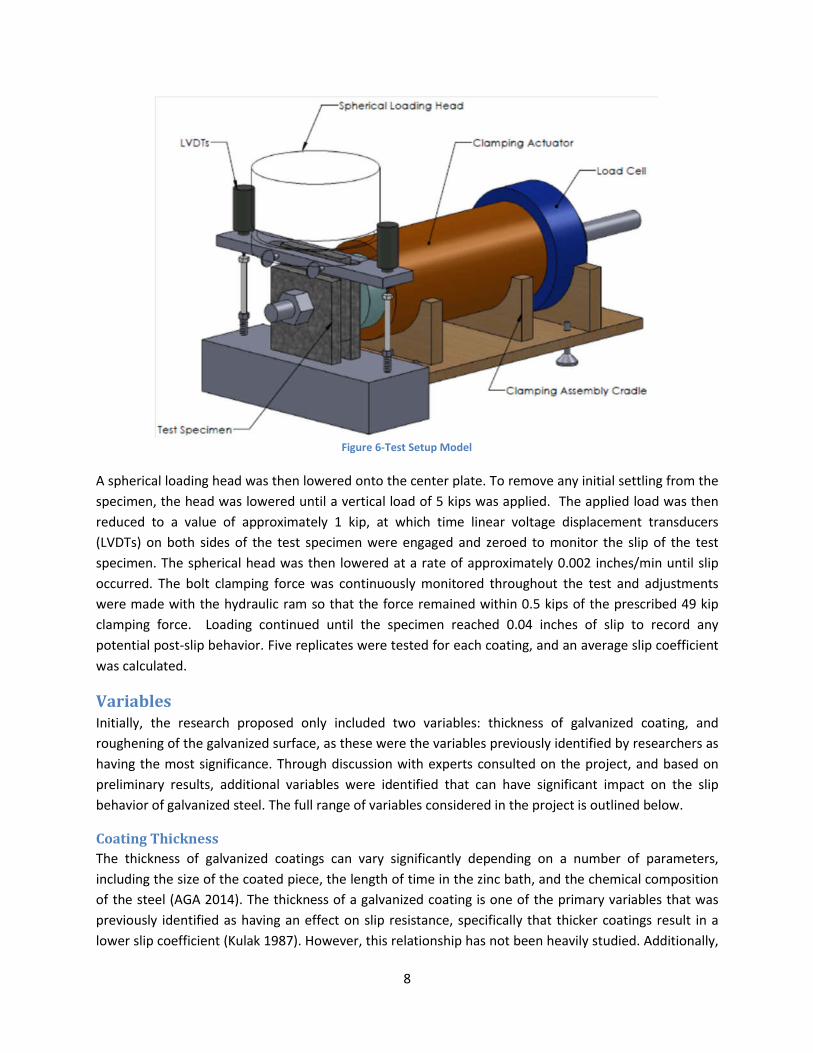
8
A spherical loading head was then lowered onto the center plate. To remove any initial settling from the
specimen, the head was lowered until a vertical load of 5 kips was applied. The applied load was then
reduced to a value of approximately 1 kip, at which time linear voltage displacement transducers
(LVDTs) on both sides of the test specimen were engaged and zeroed to monitor the slip of the test
specimen. The spherical head was then lowered at a rate of approximately 0.002 inches/min until slip
occurred. The bolt clamping force was continuously monitored throughout the test and adjustments
were made with the hydraulic ram so that the force remained within 0.5 kips of the prescribed 49 kip
clamping force. Loading continued until the specimen reached 0.04 inches of slip to record any
potential post-slip behavior. Five replicates were tested for each coating, and an average slip coefficient
was calculated.
Variables Initially, the research proposed only included two variables: thickness of galvanized coating, and
roughening of the galvanized surface, as these were the variables previously identified by researchers as
having the most significance. Through discussion with experts consulted on the project, and based on
preliminary results, additional variables were identified that can have significant impact on the slip
behavior of galvanized steel. The full range of variables considered in the project is outlined below.
Coating Thickness
The thickness of galvanized coatings can vary significantly depending on a number of parameters,
including the size of the coated piece, the length of time in the zinc bath, and the chemical composition
of the steel (AGA 2014). The thickness of a galvanized coating is one of the primary variables that was
previously identified as having an effect on slip resistance, specifically that thicker coatings result in a
lower slip coefficient (Kulak 1987). However, this relationship has not been heavily studied. Additionally,
Figure 6-Test Setup Model
9
an increased coating thickness can simply be the result of more layers of zinc being deposited, or due to
a difference in the chemical or physical structure of the coating, making it difficult to determine whether
the thickness itself is responsible for the change in slip resistance.
In order to investigate the effect of coating thickness on slip performance, the researchers desired to
have the ability to achieve different coating thickness values by varying the dip times in the zinc bath.
Based upon a discussion with galvanizing experts, the researchers selected a heat of steel with a
relatively high silicon content, which makes the steel more reactive in the zinc bath. After surveying
various vendors, the steel with the highest silicon content the researchers could locate was an A36 steel
with a silicon content of 0.28%. Steels with silicon content greater than 0.25% are considered “reactive”
with the molten zinc, readily gaining more layers of zinc coating the longer it is left in the zinc bath (AGA
2014). Thus, the thickness of the galvanized coating can be increased without significantly changing the
structure of the coating in other ways. The use of the steel with the higher silicon content enabled the
researchers to gain variations in the coating thickness without concern of other variables skewing the
data. Based upon the initial test results the researchers added a non-reactive steel with a lower silicon
content to investigate the impact of the steel chemistry on the slip performance of the galvanized
coating.
Steel Chemical Composition
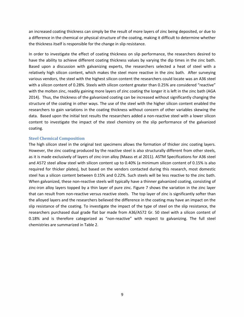
The high silicon steel in the original test specimens allows the formation of thicker zinc coating layers.
However, the zinc coating produced by the reactive steel is also structurally different from other steels,
as it is made exclusively of layers of zinc-iron alloy (Maass et al 2011). ASTM Specifications for A36 steel
and A572 steel allow steel with silicon content up to 0.40% (a minimum silicon content of 0.15% is also
required for thicker plates), but based on the vendors contacted during this research, most domestic
steel has a silicon content between 0.15% and 0.22%. Such steels will be less reactive to the zinc bath.
When galvanized, these non-reactive steels will typically have a thinner galvanized coating, consisting of
zinc-iron alloy layers topped by a thin layer of pure zinc. Figure 7 shows the variation in the zinc layer
that can result from non-reactive versus reactive steels. The top layer of zinc is significantly softer than
the alloyed layers and the researchers believed the difference in the coating may have an impact on the
slip resistance of the coating. To investigate the impact of the type of steel on the slip resistance, the
researchers purchased dual grade flat bar made from A36/A572 Gr. 50 steel with a silicon content of
0.18% and is therefore categorized as “non-reactive” with respect to galvanizing. The full steel
chemistries are summarized in Table 2.

10
Differences between Galvanizers
Though the galvanizing process has become more controlled in modern times, current specifications still
allow galvanizers some freedom in how they produce the zinc coating. One significant variation between
galvanizers is the use of different pickling acids. Hot-dip galvanizing requires the coated specimens to be
cleaned by dipping them in a pickling bath prior to immersion in the zinc bath. Modern galvanizers use
either sulfuric acid or hydrochloric acid to pickle the steel. These two acids react differently with the
steel, and may produce slightly different responses. In particular, the sulfuric acid bath can slightly
corrode the base metal, while the hydrochloric acid does not (Langill and Lee 1998). This slight corrosion
from the sulfuric acid can lead to a pitted steel surface (See Figure 8). This roughened surface of the
steel may carry over to the surface of the galvanized coating and impact the slip performance. Research
by Zennaro (1971), among others, showed that roughening of steel (by grit blasting) prior to dipping in
the zinc bath improved the slip coefficient of the galvanized surface. The roughened steel surface also
has more surface area (on a microscopic level), and thus could react more strongly with the molten zinc,
producing more zinc-iron alloy layers and fewer layers of pure zinc. Two galvanizers who use sulfuric
pickling baths and two who use hydrochloric pickling baths were used for galvanizing the test specimens
to determine what effect, if any, this has on the slip resistance of galvanized steel.
Delta Layer (90% Zinc, 10%
Iron, 244 DPN Hardness)
Zeta Layer (94% Zinc, 6%
Iron, 179 DPN Hardness)
Eta Layer (100% Zinc,
70 DPN Hardness)
Figure 7 - Physical Structure of Zinc Coatings of Non-Reactive and Reactive Steel http://www.galvanizeit.org/designing-for-hot-dip-galvanizing/design-fabrication/steel-chemistry-surface-condition
Table 2 - Chemical Composition of Tested Steels

11
The galvanizing specification allows galvanizers to add alloys to the zinc bath (up to 2% of the total
volume). Galvanizers typically add such alloys (such as nickel or aluminum) to try and minimize the
effect of reactive steels and ensure a smooth, shiny coating. The effect of such alloys on the slip
behavior of galvanized connections has not been investigated. The galvanizers selected on this project
agreed to disclose limited information on the admixtures used, and thus preliminary conclusions as to
the effect of these alloys may be inferred, but the exact relationship between bath chemistry and slip
performance is outside the scope of this project.
Roughening
Current RCSC specifications require surface roughening for any galvanized connections where slip is a
concern, to bring the slip coefficient of the galvanized surfaces up to 0.35 (0.30 in current AISC
provisions). Like the un-roughened slip coefficient, this value is based primarily on a limited number of
tests conducted several years ago. Also, as noted earlier, while previous tests showed a significant
improvement in slip performance from the roughening procedures used, an increase in slip performance
was also seen when the surfaces were cleaned with acetone prior to testing. The fact that simple
cleaning of the surface raised the slip coefficient, suggests that some of the enhancement in slip
performance from the surface roughening may have been due to the removal of some surface
contaminant, and not due to a change in the zinc coating itself.
Additionally, the procedure to roughen a zinc coating is non-specific. Currently, roughening is primarily
done by applying hand wire-brushing to the galvanized surfaces. While sand-blasting can be specified to
produce a prescribed roughness in uncoated steel, producing a specific roughness with wire-brushing is
more difficult to reliably achieve. The current specifications require only that the wire-brushing be done
until the surface is visibly altered by the brushing (AISC 2010). The specifications also require that this
brushing be done by hand, as powered wire-brushing tends to polish the surface resulting in a lower slip
coefficient. Given the lack of explicitness, it is likely a worker could over or under-roughen a surface,
resulting in a lower slip coefficient than prescribed by the designer. Since wire-brushing is the most
common method of roughening (among the galvanizers used in this project), further guidance on the
effect of this roughening process and the proper technique for applying it is needed.
Figure 8 - Micrograph of (a) Pickled and (b) Overpickled Steel (Guan 2012)

12
A more detailed and prescriptive roughening procedure was developed and tested as part of this
research. Specimens were brushed with 6 cycles of approximately 2” strokes (perpendicular to the shear
load applied during testing) with 10 pounds of force applied to the wire brush. Due to the size of the
brush, this procedure was done with the brush positioned immediately above the centerline of the bolt
hole, and immediately below the centerline of the bolt hole, in order to roughen the entire faying
surface of the test plates. To investigate the impact of the method of roughening, a second method was
also tested using 80 grit sandpaper attached to a sanding block. Similar to the wire brushing method,
this procedure was done with 6 cycles of 2” strokes with 10 pounds of load applied to the sanding block.
Due to the size of the sandpaper, the entire faying surface was simultaneously roughened, and was not
repeated above and below the bolt centerline, as with the wire brushing. The process used for the sand
paper roughening is shown in Figure 9.
Although there was not sufficient time on this project to investigate the impact of setting time between
roughening and testing, some of the galvanizers consulted on the project expressed concern that the
effectiveness of roughening galvanized coatings can be time dependent. Roughening is typically done by
the galvanizer soon after the coating is applied, and the roughened pieces can spend months in storage
before erection. This delay between roughening and service can allow significant growth of the zinc
patina, potentially filling in the grooves left by the brushing and reducing the effectiveness of the
roughening. To prevent this effect from potentially skewing data, roughening of each set of specimens
was done approximately 24 hours prior to testing.
Figure 9 - Roughening Setup
13
Spinning of Plates
When galvanizing bolts or other threaded items, it is common for galvanizers to “spin” the pieces
immediately after removal from the zinc bath (ASTM 2009). This involves placing the pieces in a
centrifuge, and spinning them at a high rate of speed to remove any excess zinc deposits that can form
during withdrawal. While this is normally done to improve fit-up between pieces, this can also remove
much of the pure-zinc layer that forms on the outside of non-reactive steel pieces. Thus, the galvanized
coating that forms on a non-reactive steel piece could be similar in structure to the coating that forms
on a reactive steel coating, with an outer layer that is formed of an iron-zinc alloy, producing a different
slip coefficient.
One shipment of test plates was spun by the galvanizer, resulting in much higher slip coefficients than
expected. As this effect was noticed near the end of the project, minimal time remained to investigate
this effect. A second group of non-reactive steel plates was galvanized by this galvanizer with one set
spun and one set not spun to investigate the effect of this process on the final slip coefficient. A
matching group of plates was sent to a fifth galvanizer (who had the capacity to spin the plates and
return them in a timely manner) to increase the sample size for this variable.
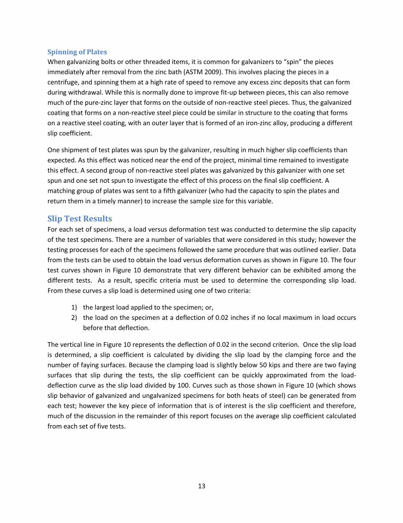
Slip Test Results For each set of specimens, a load versus deformation test was conducted to determine the slip capacity
of the test specimens. There are a number of variables that were considered in this study; however the
testing processes for each of the specimens followed the same procedure that was outlined earlier. Data
from the tests can be used to obtain the load versus deformation curves as shown in Figure 10. The four
test curves shown in Figure 10 demonstrate that very different behavior can be exhibited among the
different tests. As a result, specific criteria must be used to determine the corresponding slip load.
From these curves a slip load is determined using one of two criteria:
1) the largest load applied to the specimen; or,
2) the load on the specimen at a deflection of 0.02 inches if no local maximum in load occurs
before that deflection.
The vertical line in Figure 10 represents the deflection of 0.02 in the second criterion. Once the slip load
is determined, a slip coefficient is calculated by dividing the slip load by the clamping force and the
number of faying surfaces. Because the clamping load is slightly below 50 kips and there are two faying
surfaces that slip during the tests, the slip coefficient can be quickly approximated from the load-
deflection curve as the slip load divided by 100. Curves such as those shown in Figure 10 (which shows
slip behavior of galvanized and ungalvanized specimens for both heats of steel) can be generated from
each test; however the key piece of information that is of interest is the slip coefficient and therefore,
much of the discussion in the remainder of this report focuses on the average slip coefficient calculated
from each set of five tests.

14
A total of 190 galvanized slip tests were completed during this research study. The number of tests
conducted exceeds the range of 60-100 total tests that were originally estimated in the proposal. The
larger number of tests is primarily due to the decision by the researchers to obtain an additional set of
specimens from a different grade of steel. As noted earlier in this report, based upon recommendations
from the galvanizing industry, the researchers selected an A36 steel with a relatively high silicon content
to enable significant variation in galvanized coating thickness. Based upon the first series of tests, the
researchers observed a relatively high slip coefficient in all of the slip tests performed on the as-
galvanized (un-roughened) pieces. As a result, specimens comprised of dual grade A36/A572 Gr. 50 steel
were fabricated to provide additional information on the impact of steel chemistry on the slip behavior.
As noted earlier, the second set of steel specimens have a silicon content of 0.18% versus the 0.28% of
the original specimens.
Current RCSC recommendations suggest a slip coefficient of 0.2 for un-roughened galvanized plates. The
un-roughened galvanized plates tested in this program have an average slip coefficient of 0.48 for
reactive steels and 0.33 for non-reactive steels. In fact, many un-roughened galvanized surfaces
exceeded the slip coefficient of the bare steel, typically assumed to have much higher slip capacity than
unroughened galvanized steel. This finding suggests that current provisions on slip performance of
galvanized connections may be overly-conservative. Table 3 provides a summary of all tests. Additional
observations about the effect of each tested variable are discussed in the following sections. Note that
in the accompanying tables/figures each reported value represents the average slip coefficient from a
Figure 10 - Load-Slip Curve for Galvanized and Ungalvanized Plates

15
set of five tests. Specimens from the high silicon A36 steel are designated as “Reactive” while specimens
from the low silicon dual grade A36/A572 Gr. 50 steel are designated as “Non-Reactive”. The two
galvanizers that use sulfuric acid in their pickling bath are designated as “Sulf 1” and Sulf 2”, while the
three galvanizers that use hydrochloric acid in their pickling bath are designated as “Hydro 1”, “Hydro 2”
and “Hydro 3”. As noted earlier, the third galvanizer “Hydro 3” was added toward the end of the test
program to investigate spinning of the plates. Specimens left in the bath for the typical time used by the
galvanizers are designated as “Standard”, while those left in the bath for approximately double the
standard time are designated as “Thick”. “Sand” and “Wirebrush” refer to specimens that were
roughened by sandpaper or manual wirebrushing, respectively. “Spun” refers to plates that were placed
in the centrifuge after removal from the zinc bath to remove excess zinc. “Zinc Rich Paint” refers to a
test conducted on plates coated entirely in the zinc-rich paint used in touch-ups of the galvanized plates.

16
Differences between Galvanizers
The four galvanizing companies used in the study produced specimens with significantly different slip
coefficients. One variable that was believed to lead to a difference in the slip coefficient is difference in
pickling acids. However, as can be seen in Figure 11, the use of sulfuric or hydrochloric pickling acid does
not demonstrate a consistent trend in the measured slip performance of a galvanized piece. Due to the
Table 3 - Summary of Tested Slip Coefficients

17
high degree of scatter in these results, a conclusive statement cannot be made with regard to the
impact of pickling acid on the measured slip coefficient.
The difference between galvanizers is more likely due primarily to the different chemistries of the zinc
bath. In order to produce attractive, resilient coatings, most galvanizers add small amounts of other
metals to the zinc bath. Additionally, the zinc bath accumulates trace amounts of other metals from the
various steels dipped into the bath. In the bath chemistries of some galvanizers used on the project,
these added metals are sometimes present in quantities shown to have significant effects on the
formation of galvanized coatings (For example, nickel and aluminum can alter coating structures in
concentrations less than 0.1%). Thus, it is very difficult to identify trends between bath chemistry and
slip performance, as each bath has a large number of variables that can affect the structure of the
galvanized coating. While a particular admixture that causes better or worse slip performance cannot be
identified, the scatter among galvanizers is more significant in the case of reactive steels compared to
non-reactive steels. This makes sense, as the added metals are intended primarily to control the growth
of the inter-metallic layers of the galvanized coating (Culcasi 1999), and not intended to affect the pure-
zinc layer that typically forms on the outside of non-reactive galvanized steels. Thus, although different
galvanizers can produce very different slip coefficients, a lower bound estimate of their slip coefficient
(which will typically be controlled by non-reactive steels) will be relatively consistent between
galvanizers.
Figure 11 - Slip Coefficient of Galvanized Plates with Different Pickling Acids

18
Bath chemistry varies between galvanizers due to the addition of different alloys, but bath chemistry at
a single galvanizer can also vary over time. Galvanizers periodically check their bath chemistry, and the
exact percentage of each alloy can vary over time. Slip tests were done on plates galvanized by the same
company at two different dates (approximately three months apart). These tests can be seen in Figure
14 which shows the results grouped based upon multiple visits to the same galvanizer. The figure
includes data from the standard thickness and increased thickness tests, so two data points are shown
for each trip. While there is some change in the slip values at the two dates, the effect is limited, and it is
likely that the small variance in bath chemistry over time is not a significant influence on the slip
performance of galvanized connections.
Figure 12 - Slip Coefficient of Different Galvanizers for Reactive Steels
Figure 13 - Slip Coefficient of Different Galvanizers for Non-Reactive Steels

19
Coating Thickness
Figure 15 shows the relationship between slip coefficient and coating thickness. As noted earlier, each
marker represents the average slip coefficient of five tests, and the graphed coating thickness is likewise
the average thickness of those five specimens. The use of high silicon steel did enable significant
variability in the thickness of the galvanized coating, with the coating thickness approximately linearly
related to the time dipped in the zinc bath. The low silicon steel also developed a thicker zinc coating if
left in the bath longer, but the effect was much less significant. The tests indicate that there is an inverse
relationship between coating thickness and the slip coefficient. However, much of this is due to
differences between galvanizers, as the galvanizer that produced the thickest coating also produced
relatively low slip coefficients, but these facts are believed to be unrelated. If the values from each
galvanizer are examined separately (as in Figure 16), this trend is significantly reduced. Thus, the effect
of coating thickness on slip behavior appears to be minimal.
A more significant effect noticed due to coating thickness is that the thicker zinc coatings were more
likely to be brittle, and to have localized fractures in the zinc coating. Thus the thicker coatings generally
required a higher frequency of touch up repairs with the zinc-rich paint, which when tested as the sole
coating, had a lower slip resistance than the tested pieces (see Table 3– “Zinc-Rich Paint). However,
these local touchup repairs were typically over a very small portion of the affected area. Comparing the
results of specimens with and without paint does not indicate any noticeable effect on slip performance
due to the application of the paint.
Figure 14 - Slip Coefficient of Plates Galvanized at Different Times

20
Figure 15 - Slip Coefficient of Galvanized Plates versus Coating Thickness (for Reactive Steels)
Figure 16 - Slip Coefficient of Galvanized Plates versus Coating Thickness for Single Galvanizer

21
Steel Chemical Composition
Figure 18 shows the data grouped based upon the steel chemistry. The reactivity of the galvanized steel
seems to be the most significant variable investigated. The effect of steel chemistry can be seen in the
data and can also be observed on a purely visual basis as shown in Figure 17. The reactive steel with the
higher silicon content has a relatively smooth (apart from isolated deposits), matte appearance, due to
the coating having zinc-iron alloys throughout its full thickness. The non-reactive steel with the lower
silicon content comparatively has a more textured, shiny appearance, due to the layer of pure zinc on
the outside of the coating. Despite the rougher appearance of the non-reactive/low silicon steel, the
soft pure-zinc layer seems to act as a lubricating surface, producing a significantly lower slip coefficient
than the reactive/high silicon steel galvanized at the same time.
Figure 17 - Different Surface Conditions of Reactive and Non-Reactive Steel
Reactive Non-Reactive

22
Roughening
The slip coefficients of 0.30 and 0.35 specified in the respective AISC and RCSC provisions are specified
for roughened galvanized coatings. One of the goals of this research study was to investigate the impact
of the roughening on the slip coefficient and to potentially recommend more effective surface
preparations for improving the slip coefficient. As mentioned previously, the two heats of steel had very
visually distinct galvanized surfaces. These different surfaces, in addition to affecting the slip
performance of the specimens, seemed to affect how the specimens responded to the roughening
treatment. As shown in Figure 19, the zinc-iron alloy finish of the high silicon steel was visibly altered to
a significant degree by the roughening procedure. The low silicon steel, due to the softness of the pure
zinc layer and the existing surface variation left by the galvanizing, did not appear to be significantly
affected by the roughening procedure as shown in Figure 20. In an attempt to visibly alter the surface in
compliance with specifications, extra specimens were roughened with higher applied force and more
strokes, but the researchers were unable to produce a significantly altered appearance. Thus, the low
silicon steel was tested using the same roughening procedure as the high silicon steel to maintain
consistency.
Figure 18 - Slip Coefficients of Reactive and Non-Reactive Steels

23
The data from the roughened plates is shown in Figure 21 and Figure 22. Roughening the high silicon
steel did not noticeably improve the slip performance of the tested specimens. It is possible the
roughening was not sufficient, and the slip resistance could be improved by a more thorough
roughening procedure, however with regards to hand brushing the surface, the 10-pound force seems
like a reasonable force that a worker is likely to consistently deliver. Although the measured slip
coefficient was not significantly altered by the roughening, it can be observed in Figure 23 that the load-
deformation responses of the sandpaper roughened specimens are noticeably different than the un-
roughened specimens. Most sandpaper roughened specimens demonstrated a significantly more brittle
Figure 19 – Un-roughened and Sanded Appearance of High Silicon/Reactive Steel
Figure 20 – Un-roughened and Sanded Appearance of Low Silicon/Non-Reactive Steel
Unroughened Sanded
Unroughened Sanded

24
behavior and unloaded very suddenly, instead of the more ductile response seen in the un-roughened
specimens. Given the very high slip resistance of the tested specimens, it is likely the as-galvanized
surface was already sufficiently rough such that sanding or brushing could not improve the
performance.
Similar to the results from the high-silicon steel, roughening the low silicon steel also did not improve
the slip performance of the tested specimens. Unlike the high silicon steels though, the behavior of the
roughened and un-roughened specimens did not affect the ductility as shown in Figure 24. Thus, it is
possible that the specimens were not sufficiently roughened to alter their slip performance and a more
thorough roughening procedure could improve the performance of the steel. However, as noted above,
the 10-pound force that was applied to the wire brush and sandpaper is likely a representative value
that is applied in practice. Therefore, these results are likely representative of the surface roughening
that is found in practice. Given the difficulty encountered in this research in producing a visibly altered
appearance, it is likely that this rougher surface (if it is possible) cannot be reliably achieved through
manual roughening methods.
Figure 21 - Slip Coefficients of Wire-brushed Specimens

25
Figure 22 - Slip Coefficient of Sanded Steels
Figure 23 - Slip Performance of Roughened Steel (First Hydrochloric Acid Using Galvanizer, Reactive Steel)

26
Spinning of Plates
Some galvanizers use the practice of spinning smaller galvanized pieces immediately following removal
from the zinc bath to remove excess zinc deposits. However, this practice can also remove the outer
layer of pure zinc from a piece. Given the large impact galvanized coating structure had in other tests in
this study, obtaining a measure of the impact of spinning on the slip performance was desirable.
Spinning galvanized plates after removal from the zinc bath did result in a noticeable change in the
galvanized coating. For the test set that contained spun and un-spun plates, the spun plates possessed
coatings that were approximately half as thick as the un-spun plates galvanized under the same
conditions. The spun plates also had an appearance that was dull in comparison with the coatings from
the un-spun plates, suggesting that the outer layer may be composed of the zinc-iron alloys seen in
reactive steels, instead of the expected pure zinc layer (See Figure 25). Despite this, the enhancement in
slip performance was limited, with one galvanizer showing no improvement, and one galvanizer showing
an increase from 0.45 to 0.49, within the standard deviations of the tests (See Table 3). Given the
abnormally high slip coefficient seen in the initial spun tests, it is still possible that spinning the plates
can improve their slip performance. However, it would likely require tight quality control to ensure the
spinning produces the desired effect. More research on this effect is needed to obtain a more
statistically relevant sample before any conclusions can be drawn.
Figure 24 - Slip Performance of Roughened Steel (First Hydrochloric Acid Using Galvanizer, Non-Reactive Steel)

27
Bolt Creep Beyond the slip coefficient of the faying surface, another equally important factor in the slip resistance
of the connection is the clamping force. For connections with uncoated steel, this preload can be
predicted with reasonable accuracy by approved tightening methods, and the clamping load will be
reasonably maintained over the life of the structure. However, unlike steel, zinc exhibits significant
creep behavior if left under constant load. In a galvanized steel connection, the layers of zinc on the
fasteners and connected surfaces can undergo significant creep strain, reducing the strain in the bolt
and thereby lowering the clamping force the bolt applies to the connection. However, the extent to
which creep affects the preload in a typical connection is not well understood. This research examined
this effect in further detail.
The bolt creep tests performed as part of this research were performed on test specimens identical to
those used for the slip tests. However, rather than the clamping force being applied through an
actuator, the creep specimens were loaded through the tightening of a 3-1/2” long, 7/8” diameter A325
bolt. Strain gages were installed in small holes drilled into the shaft of the bolt in order to monitor the
magnitude of the clamping force. The bolts were tightened to approximately 10% above the specified
preload (42.9 kips), and the axial force in the bolt was monitored for 1000 hours (creep after that length
of time is usually not significant) to determine the total loss in clamping force expected for that
connection. Each variable investigated in the tests had three replicates.
Sixteen galvanized bolts from the same lot were obtained and strain gages were installed in holes drilled
into the bolt shaft (See Figure 26). A calibration test was performed on each bolt to obtain a curve of
the load versus strain gage reading for each specific bolt. During calibration, the bolts were hydraulically
loaded through the Skidmore-Wilhelm Bolt Calibrator as shown in Figure 27 to avoid stripping the
Figure 25 - Appearance of Unspun and Spun Plates
Unspun Spun

28
galvanizing in the threads during bolt tightening. A representative curve of the bolt gage load as a
function of the Skidmore load is shown in Figure 28.
Figure 26 - Test Specimen with Gaged Bolt
Figure 27 - Calibration of Gaged Bolt through Hydraulic Tension Calibrator

29
The cause of creep in a galvanized connection can be grouped into two sources: creep in the fasteners
(bolts, nuts and washers), and creep in the connected pieces. As mentioned previously, galvanized
coatings on connected steel pieces can vary significantly in both thickness and structure. The effect of
both of these variations on creep behavior was examined in the test matrix. While the galvanized
coating on fasteners can also vary, this is likely less significant, as the ASTM Specifications for the bolt
and washer material have tighter limits on steel chemistry. The thickness is also likely to vary less as very
thick coating will fail the fit-up test required for galvanized bolts and nuts. Thus, in order to limit the size
of the test matrix, all galvanized bolts, washers, and nuts were taken from the same lot. The thickness of
each fastener component’s galvanized coating was measured with the same Elcometer gage used to
measure the galvanized plates. Due to the difficulty of measuring coating thickness on threaded areas,
the bolt coating thickness was taken from three flats of the bolt head, and the nut thickness was
measured from three of its outer flats.
High silicon steel was used for two sets of test specimens to allow greater variation in values of the
coating thickness. As with the slip test specimens, one set of plates was galvanized with a normal
coating thickness and one set of plates was galvanized with a thickness approximately double that of the
first set. Due to the high silicon content, these samples both appear to contain exclusively hard layers of
zinc-iron alloys. Thus, one set of low silicon specimens was also galvanized. These specimens contain a
layer of pure zinc in the galvanized coating, which may be more susceptible to creep than the alloyed
coating. In order to enable more direct comparison between chemistries, this set of plates was left in
the zinc bath for an extended period of time, to better match the thickness of the more reactive steel.
Two sets of plates were also left un-galvanized, one of which was tested with normal galvanized bolts to
determine the creep purely due to the coatings on the hardware. The second set of galvanized plates
Figure 28 - Bolt Gage Load vs Tension Calibrator Load

30
was tested with un-galvanized bolts to serve as a control sample for comparison. In order to ensure
uniformity, these bolts were taken from the same lot of galvanized bolts, and their zinc coatings were
removed by immersion in hydrochloric acid. The nuts used with the un-galvanized bolts were black oxide
A563 nuts, rather than galvanized nuts with the zinc removed by acid. As galvanized nuts are over-
tapped (to allow fit-up with the galvanized bolts after the zinc coating is applied), their use with the un-
galvanized bolts would not be representative of typical practice. The un-galvanized plates were taken
from the high-silicon heat of steel. A final bolt was left un-tightened and monitored to detect any
potential change in the system unrelated to loss in clamping force (such as thermal effects).
The specimens were all assembled, with the bolts left untightened, and initial strain readings were taken
from each specimen. The data acquisition system was then set to record axial load readings at one
minute intervals (this frequency was later increased to every hour, then every six hours, as the rate of
loss slowed). Each specimen was first hand-tightened with a spud wrench to ensure full contact among
the components. The specimen was then clamped firmly in place, and the specimen was tightened to its
final proof load via hydraulic wrench. Due to a slight lag in the display of strain gage readings, there was
some imprecision in the tightening of the bolts. While this could have been reduced with a slower
tightening procedure, a slower tightening procedure could have resulted in small amounts of creep
occurring during tightening which would have been missed by the test setup. Thus, the specimens were
tightened to within approximately 5% of the target load, which enabled the specimens to be completely
tightened in approximately one minute, minimizing any effect of creep during tightening. The average
preload of each set of specimens is very close to the target preload, and the research team believes this
scatter did not have a significant impact on the final behavior.
Bolt Creep Results A graph of the average loss in preload for all test cases is shown in Figure 30. Due to the previously
mentioned scatter in initial load, the values are shown as fractional losses from the initial preload, not
Figure 29 - Creep Test Specimens

31
absolute losses, to enable better comparison. The preload in the connection is also calculated at a time
one minute after tightening. This is frequently done in bolt creep tests, as the loss in clamping force in
the period immediately after tightening is believed to be due to elastic recovery from removal of the
wrench, and not actual creep behavior (Kulak et al 1987). The data also includes a correction factor from
the un-loaded bolt, as the specimens exhibited mild cyclic fluctuations in bolt tension (assumed to be
due to thermal effects). Conclusions from the tests are discussed below.
Figure 30 - Loss in Preload over Time

32
Mill Scale
As expected, the specimens with black bolts and plates exhibited very little creep, with an average loss
of approximately 2.5% over the life of the tests. Due to instrumentation problems during tightening,
data from one of the test specimens was not available, and only two specimens are shown. However,
the results are consistent with previously reported findings by Munse (1967) and others, and their use
as a control is reasonable.
Galvanized Hardware
The use of galvanized fasteners contributed significantly to the creep of the galvanized connections. This
is reasonable, as the use of galvanized hardware adds many galvanized surfaces to the connection from
the washers, bolt and nut. The loss in preload is consistent with values reported by Slutter (1985) at 70
hours (when their test was stopped). However, the final loss is noticeably larger than values reported in
Munse (1967). The reason for this discrepancy is not certain, but is possibly due to the significantly
longer bolts used in the Munse tests, which had a 4-7/8” grip, as opposed to the 1-1/2” grip in the tests
carried out in the present study. This greater grip length meant that a similar level of absolute creep
deformation would result in a smaller reduction in overall bolt strain, limiting the loss due to creep. This
implies that connections with shorter grip lengths could undergo more relaxation than that predicted by
the set-up in this study, and the corresponding predictions from this study could be unconservative in
those cases; however the 1-1/2” grip used in the present studies is well representative of typical grips
frequently used in practice. The effect of grip length on bolt relaxation is a potential subject requiring
future study.
Steel Chemistry
Steel chemistry had a large impact on the loss in bolt preload, as the non-reactive steel experienced
significantly more relaxation than the reactive steel. This is likely due to the presence of the pure zinc
Table 4 - Summary of Final Losses in Preload

33
layer on the outside of the non-reactive steel’s coating, which is significantly softer than the zinc-iron
alloy layers, and appears to also exhibit much more creep behavior. Note that although the tests in this
study were done on the effect of steel chemistry, the true cause of the increase in creep loss is believed
to be the change in the physical structure of the coating, which can be effected by other variables,
particularly the withdrawal rate. The eta layer (the soft, pure zinc layer that seems to exhibit the most
creep behavior) is formed during withdrawal from the zinc bath, and faster withdrawal rates will result
in thicker eta layers being left on the piece (AGA 2014). In order to reduce consumption of zinc from the
bath, modern galvanizers tend to use slow withdrawal rates. The galvanizers used in this research all
used withdrawal rates of between 2 and 3 feet per minute when galvanizing the specimens, which is
consistent with values reported by other researchers (Shawki and Hamid 2003, Fratesi et al 2003).
However, ASTM standards do not specify a withdrawal rate for galvanized pieces, and this likely varies
between galvanizers. Observations of other galvanized pieces during the site visits to the galvanizers
showed that larger pieces were typically withdrawn from the zinc bath at a slower rate. Thus, although it
is difficult to definitively predict the thickness of the eta layer, it is likely that the specimens in this study
represent an upper bound on eta layer thickness, and thus an upper bound on loss of clamping force.
Coating Thickness
The difference in coating thickness had little impact on the creep of the tested specimens. This seems to
agree with the assumption that the creep in the galvanized plates is due primarily to the pure zinc layer
on the outside of the non-reactive steel. Increases in zinc coating thickness are typically attributed to the
growth of the middle delta layer (the moderately hard, 6% iron layer), which spreads into the zeta and
eta layers as the steel continues to react with the molten zinc (Marder 2000). Thus, a thicker zinc coating
likely does not lead to a thicker eta layer on the galvanized piece, and thus has limited effect on the
creep of the connection.
This finding is in contrast to research conducted by Yang (1998) that showed a small but significant
increase in the loss of preload with increased coating thickness (See Table 5). Note that the average
values in the table are calculated by the author, and do not match the averages given by Yang; the
reason for this discrepancy is unknown. It is possible there is an effect of coating thickness on bolt
relaxation that was missed in the current test program due to scatter. It is also possible that the
increased thickness in Yang’s research was achieved through a different method than in the present
research study (such as changing the zinc bath temperature) which can affect the structure of the zinc
coating in different ways (Kania 2014). Although very thick zinc coatings could lead to higher amounts of
bolt relaxation, such thick coatings are generally only seen in reactive steels. As non-reactive steels have
significantly more creep despite their lower coating thickness, it is reasonable to assume the upper
bound on potential creep losses is typically controlled by chemistry, not coating thickness.

34
Conclusions Based on the tests done as part of this research, a number of conclusions can be drawn:
1. The slip performance of un-roughened galvanized plates is comparable to or better than the
performance of un-galvanized (mill scale) plates.
2. The thickness of a zinc coating does not have a significant impact on the slip coefficient of the coating.
3. The chemistry of the steel can have a significant impact on the slip coefficient of the galvanized-
coated steel, with more reactive steels (such as steels possessing higher silicon content) exhibiting
higher slip loads than non-reactive steels.
4. The slip coefficient of a galvanized piece is dependent on the galvanizer used.
5. The practice of roughening galvanized pieces through wire-brushing or sanding results in no
significant improvement in slip performance.
6. The presence of zinc coating on a fully-tightened connection results in a significant loss in clamping
force over time due to zinc creep.
7. The thickness of a zinc coating does not have a significant impact on the loss in clamping force
exhibited by a fully tightened bolt.
8. The chemistry of galvanized steel has a significant impact on the loss in clamping force, with non-
reactive steel experiencing significantly more relaxation than reactive steel.
Recommendations
Slip Coefficient Many of the specimens tested in this research significantly exceeded the 0.3 slip coefficient currently
used by the AISC specifications. However, the specimens that exhibited this higher slip resistance were
predominantly taken from a reactive heat of steel. Based on experiences of the research team in
locating reactive steel specimens, most steels do not have sufficient silicon (or other reactive metals) to
exhibit this behavior. Thus, in order to represent the behavior of typical galvanized connections, (while
Table 5 - Losses in Preload for Different Coating Thickness Reported by Yang

35
still maintaining a reasonable degree of conservatism) the researchers recommend the use of a slip
coefficient based on the results of the non-reactive steel. Based on this criterion, the existing slip
coefficient of 0.3 has good agreement with the the test data and does not need to be changed.
However, this slip coefficient is given for galvanized surfaces that have been roughened by wire-
brushing or sand-blasting. The test results indicate that roughening the surface of galvanized pieces is
not necessary to achieve the specified slip coefficient, and does not seem to improve the slip behavior of
the connections to a significant degree. Thus, the researchers recommend that the requirement for
roughening galvanized surfaces be removed from the specifications.
Bolt Relaxation The tests indicate that pre-tensioned connections with galvanized surfaces can experience a significant
loss in clamping force during the service life of a structure. This loss in bolt preload will likely correspond
to a loss in the slip capacity of the connection, and thus needs to be considered by engineers in the
design of connections. Based on the test results, the researchers recommend engineers design
galvanized connections assuming a 17.5% reduction in the initial preload of the bolt.
The test results indicated that the reduction in clamping force was primarily dependent on the thickness
of the pure-zinc layer on the outside of a typical galvanized surface. Thus, the primary variables that
affect this loss are the chemistry of the steel and withdrawal rate from the zinc bath during galvanizing.
The use of reactive steel will likely result in a decrease in the thickness of the eta layer, and the assumed
reduction should be conservative. However, if a galvanizer uses an abnormally high withdrawal rate
during galvanizing, a thicker eta layer could result, and the reduction in clamping force could exceed the
assumed value.
Acknowledgments The testing program outlined in this report was funded by the American Institute of Steel Construction
and the Research Council on Structural Connections. The authors would like to thank AISC and RCSC for
funding this effort. The authors would also like to thank AZZ Galvanizing-Crowley, K-T Galvanizing Co.-
Katy, Madden Galvanizing LLC, Sabre Galvanizing, and Southwest Galvanizing, Inc. for the donation of
galvanizing services on the project. Special thanks are extended to Harold Maier and Hirschfeld
Industries for the assistance in specimen fabrication. Special thanks are also given to Dr. Tom Langill of
the American Galvanizing Association for providing consultation during the planning phases of the
research. The authors appreciate the donation of galvanized hardware from Lohr Fasteners. Finally, J.R.
Watson of the UT Applied Research Laboratory provided machining services for the creep tests, which
was greatly appreciated.

36
Works Cited American Institute of Steel Construction, Code of Standard Practice for Steel Buildings and Bridges, AISC, Chicago, 2010. American Society for Testing and Materials, Standard Specification for Carbon Structural Steel, ASTM Designation A325-10 (originally issued 1960), 2010. American Society for Testing and Materials, Standard Specification for Hardened Steel Washers, ASTM Designation F436-11 (originally issued 1976), 2011. American Society for Testing and Materials, Standard Specification for High-Strength Low-Alloy Columbium-Vanadium Structural Steel, ASTM Designation A572-13 (originally issued 1966), 2013. American Society for Testing and Materials, Standard Specification for Structural Bolts, Steel, Heat Treated, 120/105 ksi Minimum Tensile Strength, ASTM Designation A36-12 (originally issued 1964), 2012. American Society for Testing and Materials, Standard Specification for Zinc Coating (Hot-Dip) on Iron and Steel Hardware, ASTM Designation A153-09 (originally issued 1933), 2009. American Society for Testing and Materials, Standard Specification for Zinc (Hot-Dip Galvanized) Coatings on Iron and Steel Products, ASTM Designation A123-13 (originally issued 1928), 2013. Brookhart, George C., I. H. Siddiqi, and D. D. Vasarhelyi. "Surface Treatment of High-Strength Bolted Joints." Journal of the Structural Division, 1968. Birkemoe, P.C. and D. C. Herrschaft, “Bolted Galvanized Bridges—Engineering Acceptance Near,” Civil Engineering, April 1970. Culcasi, J. D., et al. "Control of the growth of zinc–iron phases in the hot-dip galvanizing process." Surface and coatings technology. Vol. 122 No. 1, 1999. Fratesi, R., et al. "Contemporary use of Ni and Bi in hot-dip galvanizing."Surface and Coatings Technology, Vol. 157 No. 1, 2002. Fisher, John W., John HA Struik, and Geoffrey L. Kulak. Guide to design criteria for bolted and riveted joints. John Wiley and Sons, 1985. Guan, W., et al. "Effect of pickling on plating porosity and related electrochemical test." Surface Engineering. Vol. 28 No. 6, 2012. "The HDG Coating." American Galvanizing Association. Web. 14 May 2014. <http://www.galvanizeit.org/hot-dip-galvanizing/what-is-hot-dip-galvanizing-hdg/the-hdg-coating>. Kania, Henryk. "Kinetics of Growth and Structure of Coatings Obtained on Sandelin Steels in the High-Temperature Galvanizing Process." Solid State Phenomena Vol. 212, 2014.

37
Langill, Thomas and Suk Lee. “Pickling Iron and Steel,” Galvanizing Notes. Vol. 2 No. 2, June 1998. Maass, Peter, and Peter Peissker, eds. Handbook of hot-dip galvanization. John Wiley & Sons, 2011. Marder, A. R. "The metallurgy of zinc-coated steel." Progress in materials science Vol. 45 No. 3, 2000. Munse, W. H. "Structural Behaviour of Hot Galvanized Bolted Connections."Proceedings, 8th International Conference on Hot-Dip Galvanizing. 1967. Research Council on Riveted and Bolted Structural Joints of the Engineering Foundation, Specifications for Assembly of Structural Joints Using High-Strength Bolts, originally issued 1951, latest edition; Research Council on Structural Connections, Specification for Structural Joints Using ASTM A325 or A490 Bolts, 2004. Sanderson, R. A. Investigation of the fatigue behaviour of high strength bolted galvanized joints. Diss. University of Toronto, 1968. Shawki, Saher, and Z. Abdel Hamid. "Effect of aluminium content on the coating structure and dross formation in the hot-dip galvanizing process." Surface and interface analysis Vol 35. No. 12, 2003. Slutter, Roger. Tests of 7/8” Diameter A325 Bolts for Rehoboth Avenue Bridge No. 153” Lehigh University, 1985. Steinhardt, O. and K. Möhler, Versuche zur Anwendung Vorgespannter Schrauhen Stahlbau, Teil II, Bericht des Deutschen Ausschusses für Stahlbau, Stahlbau-Verlag Gmbh, Cologne, Germany, 1959. Valtinat, G., and H. Huhn. "Bolted connections of hot dip galvanized steel members with punched holes." Intergalva 2003: Twentieth International Galvanizing Conference, 2003. Yang, Jun, and John T. DeWolf. "Relaxation in high-strength bolted connections using galvanized steel." Journal of Bridge Engineering Vol. 5 No. 2, 2000. Yoon, Hyun Gi, et al. "Aerodynamic investigation of air knife system to find out the mechanism of the check mark in a continuous hot-dip galvanizing process."ASME 2008 International Mechanical Engineering Congress and Exposition. American Society of Mechanical Engineers, 2008. Zennaro L., Slip Tests of High Strength Bolted Joints with Different Galvanized Coating Structures, Document CECM-X-71-8.