FINAL REPORT 9/1/2004 - Defense Technical Information Center · FINAL REPORT 9/1/2004 ... Edgar...
58
Coherent Ion Acceleration Using Beating Electrostatic Waves FINAL REPORT 9/1/2004 to the US Air Force Office of Scientific Research GRANT NUMBER: F49620-02-1-0009 Start date:08/31/02 End date:9/1/04 PI: Prof. Edgar Choueiri Graduate Student: Rostislav Spektor Electric Propulsion and Plasma Dynamics Lab (EPPDyL) Applied Physics Group MAE Dept., Princeton University Princeton NJ 08544 Phone: (609) 258 5220 Fax: (609) 258 6875 E-mail: [email protected] 20050519 118
Transcript of FINAL REPORT 9/1/2004 - Defense Technical Information Center · FINAL REPORT 9/1/2004 ... Edgar...
Coherent Ion Acceleration Using BeatingElectrostatic Waves
FINAL REPORT9/1/2004
to the US Air Force Office of Scientific Research
GRANT NUMBER: F49620-02-1-0009Start date:08/31/02
End date:9/1/04
PI: Prof. Edgar Choueiri
Graduate Student: Rostislav Spektor
Electric Propulsion and Plasma Dynamics Lab (EPPDyL)Applied Physics Group
MAE Dept., Princeton UniversityPrinceton NJ 08544
Phone: (609) 258 5220 Fax: (609) 258 6875E-mail: [email protected]
20050519 118

REPORT DOCUMENTATION PAGE R 05-
The public reporting burden for this collection of information is estimated tol rage 1 hour per response, including the timgathering and maintaining the data needed, and completing and reviewing the collection of information. Send comments regarof information, including suggestions for reducing the burden, to Department of Defense, Washington Headquarters S,(0704-0188), 1215 Jefferson Davis Highway, Suite 1204, Arlington, VA 22202-4302. Respondents should be aware that rsubject to any penalty for failing to comply with a collection of information if it does not display a currently valid OMB control n
PLEASE DO NOT RETURN YOUR FORM TO THE ABOVE ADDRESS.1. REPORT DATE (DD-MM-YYYY) 2. REPORT TYPE 3. DATES COVERED (From - To)
01092004 Final Report 31 Aug 2002- 1 Sep 2004
4. TITLE AND SUBTITLE 5a. CONTRACT NUMBER
Coherent Ion Acceleration Using Beating Electrostatic Waves5b. GRANT NUMBER
F49620-02-1-0009
5c. PROGRAM ELEMENT NUMBER
6. AUTHOR(S) 5d. PROJECT NUMBER
Professor Edgar Choueiri5e. TASK NUMBER
5f. WORK UNIT NUMBER
7. PERFORMING ORGANIZATION NAME(S) AND ADDRESS(ES) 8. PERFORMING ORGANIZATIONApplied Physics Group REPORT NUMBERMAE DepartmentPrinceton UniversityPrinceton NJ 08544
9. SPONSORING/MONITORING AGENCY NAME(S) AND ADDRESS(ES) 10. SPONSOR/MONITOR'S ACRONYM(S)USAF/AFRLAFOSR AFOSR801 N. Randolph Street1REArlington VA 222 11. SPONSOR/MONITOR'S REPORT
NUMBER(S)
12. DISTRIBUTION/AVAILABILITY STATEMENT
Distribution Statement A. Approved for public release; distribution is unlimited.
13. SUPPLEMENTARY NOTES
14. ABSTRACTThe results obtained from AFOSR-sponsored study on a new ion acceleration using beating electrostatic waves. Unlike previouslyknown methods of energizing plasmas with electrostatic waves, and which accelerate only ions whose initial velocities are above acertain threshold (close to the waves velocity), the new mechanism can accelerate ions with arbitrarily small initial velocities. Thisresults in significant improvements to the acceleration/heating efficiency (by as much as 45%) over previous techniques. Thebenefits to the state of the art of space propulsion stem from the high efficiency of the new mechanism,its thersholdless nature andits capabilities of producing high ion energies and its electrodeless character. In summary project accomplished the following: 1Demonstrated theoretically that a new highly efficient ion acceleration mechanism by heating electrostatic (ES) waves is teal and iia fundamental phenomenon that occurs only under specific conditions. 2. Studied using Monte Carlo simulations the effects ofcollisions (that would occur in a real low temperature plasma) on the ion acceleration mechanism and found that collisions canenhance the effects due to scattering of ions out of the forbidden region of phase space. 3. Designed and constructed a dedicatedexperiment to study the new ion acceleration mechanism.15. SUBJECT TERMS
16. SECURITY CLASSIFICATION OF: 17. LIMITATION OF 18. NUMBER 19a. NAME OF RESPONSIBLE PERSON
a. REPORT b. ABSTRACT c. THIS PAGE ABSTRACT OFPAGES
SUU 57 19b. TELEPHONE NUMBER (Include area code)U U UUU5
Standard Form 298 (Rev. 8/98)Prescribed by ANSI Std. Z39.18

Contents
1 Ion Acceleration by Beating Electrostatic Waves: Domain ofAllowed Acceleration 61.1 Introduction . .. .. ... . ... .. ... . .... .. .. . . .. 61.2 Analytical Formulation ........................ 71.3 Single Wave Interaction ....................... 111.4 Multiple Wave Interaction ...................... 121.5 Topology of the Phase Diagram ................... 161.6 Critical Points ............................ 171.7 Beating Waves (On-Resonance) ................... 211.8 Summary and Concluding Remarks ................. 221.9 APPENDIX: S6'"'" (p) Term Simplification ............. 24
2 Effects of Ion Collisions on Ion Acceleration 262.1 Introduction .............................. 262.2 Single Particle Model ......................... 272.3 Including Collisions .......................... 30
2.3.1 Overall implementation ................... 302.3.2 Momentum exchange during a collision ............ 302.3.3 Moving the particles ..................... 32
2.4 Sim ulation ........................... .... 322.4.1 Phase diagrams ........................ 322.4.2 Energy Evolution ....................... 32
2.5 Conclusions .............................. 34
3 Beating Waves Experiment: Excitation of Ion Cyclotron Wavesand Demonstration of Ion Acceleration 363.1 Introduction ..................................... 363.2 Review of previous work ............................ 373.3 Experimental setup ................................ 39
3.3.1 Vacuum Chamber ...... ...................... 393.3.2 Plasma Source ........................ 413.3.3 Beating Waves Antenna ................... 41
3.4 Diagnostics .............................. 423.5 W ave launching ............................ 44
1

2
3.6 Dispersion relation measurement ....................... 463.7 Conclusions regarding ES Wave Excitation ................ 493.8 Demonstration of Ion Acceleration ..................... 49
FINAL REPORT 9/1/04: ION ACCEL. WITH BEATING WAVES 3
SYNOPSIS
In this final technical report we document, in three chapters, the resultsobtained from our AFOSR-sponsored study on a new ion acceleration usingbeating electrostatic waves.
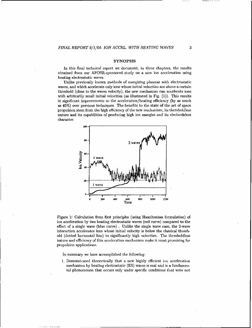
Unlike previously known methods of energizing plasmas with electrostaticwaves, and which accelerate only ions whose initial velocities are above a certainthreshold (close to the waves velocity), the new mechanism can accelerate ionswith arbitrarily small initial velocities (as illustrated in Fig. (1)). This resultsin significant improvements to the acceleration/heating efficiency (by as muchas 45%) over previous techniques. The benefits to the state of the art of spacepropulsion stem from the high efficiency of the new mechanism, its thersholdlessnature and its capabilities of producing high ion energies and its electrodelesscharacter.
2 wawes
O ' 'I waI I I
0 20o 400 600 800 1000 J2N0Time
Figure 1: Calculation from first principles (using Hamiltonian formulation) ofion acceleration by two beating electrostatic waves (red curve) compared to theeffect of a single wave (blue curve) . Unlike the single wave case, the 2-waveinteraction accelerates ions whose initial velocity is below the classical thresh-old (dotted horizontal line) to significantly high velocities. The thresholdlessnature and efficiency of this acceleration mechanism make it most promising forpropulsion applications.
In summary we have accomplished the following:
1. Demonstrated theoretically that a new highly efficient ion accelerationmechanism by beating electrostatic (ES) waves is real and is a fundamen-tal phenomenon that occurs only under specific conditions that were not

FINAL REPORT 9/1/04: ION ACCEL. WITH BEATING WAVES 4
known before. We derived, from first principles, the fundamental neces-sary and sufficient conditions for the acceleration mechanism to occur.
2. We studied using Monte Carlo simulations the effects of collisions (thatwould occur in a real low temperature plasma) on the ion accelerationmechanism and found that collisions can enhance the effects due to scat-tering of ions out of the forbidden region of phase space.
3. We designed and constrducted a dedicated experiment to study the newion acceleratio mechanism. We were able to launch and beat ion cyclotronwaves in an argon plasma produced by a helicon source and, using a ded-icated state-of-the-art LIF diagnostic system (acquired through a recentDURIP grant), we were able to provide the first laboratory de-mostration of the existence of this new ion acceleration mecha-nism.
This final technical report consists of three chapters summarized below.In Chapter 1 the conditions under which a magnetized ion can be acceler-
ated through a nonlinear interaction with a pair of beating electrostatic wavesare explored. The electric field of the beating waves can, under some condi-tions, accelerate ions from arbitrarily low initial velocity in stark contrast withthe well-known nonlinear threshold criteria for ion acceleration by a single wave.A numerical investigation of the fundamental dynamics led to the identificationof critical points on the Poincar6 cross-section. A second-order perturbationanalysis was carried out to approximate the location of these critical points anddefine the domains of allowed and forbidden acceleration. It is shown that foran ion to be significantly energized, the Hamiltonian must be outside the en-ergy barrier defined by the location of the elliptic and hyperbolic critical points.Despite the restriction on the Hamiltonian, an ion with arbitrarily low initialvelocity may benefit from this acceleration mechanism. The resulting domainof allowed acceleration is significantly larger than that of ion acceleration byeither single or non-beating waves.
In Chapter 2 a numerical model of the nonlinear interaction between beat-ing electrostatic waves and magnetized ions, including collisions, is presented.Previous studies of the beating electrostatic waves (BEW) interacting with asingle ion showed the ability of this mechanism to accelerate ions from arbitrar-ily low initial velocities, and have revealed the fundamental conditions for thisinteraction to occur. The present study extends the analysis to a large numberof ions and includes ion-ion collisions. The numerical investigation combines adynamical description for the ion-wave interaction and a Monte Carlo simulationof the collisions. Despite the thermalization role of collisions BEW accelerationwas found to yield larger heating rate and higher particle energies than thebetter known interaction with the single electrostatic wave (SEW).
In Chapter 3 we report on our experiments that demonstrate the exis-tence of the new acceleration mechanism. We first report on the excitation andpropagation of Electrostatic Ion Cyclotron (EIC) waves in an rf-sustained argonplasma and our measurements of the sought dispersion relations. Such waves

FINAL REPORT 9/1/04: ION ACCEL. WITH BEATING WAVES 5
were used to study the beating waves ion acceleration mechanism as reported in
the last section of the chapter. The waves are excited by an antenna consistingof two parallel metal plates inserted at the edge of a plasma column with theirsurface normal perpendicular to magnetic field. The plates can be driven in orout of phase. The in-phase configuration couples better to plasma. It is shownthat EIC waves launched at frequencies between wcj and l0wcj propagate withlittle damping at an angle between 820 and 86' with respect to the magneticfield. The amplitude of the excited waves can be optimized by properly match-ing the impedance of the driving circuit to the plasma and choosing the right
plasma conditions. The dispersion relation was measured using a phase-delaytechnique and was found to be in good agreement with the theoretical EIC dis-persion relation over a wide range of frequencies. We conclude that chapter andthe report with the first laboratory demonstration of the existence ofthe new ion acceleration mechanism by directly measuring a significant(up to 40%) increase in the perpendicular ion energy.
Acknowledgements This work has been carried out under contract fromthe US Air Force Office of Scientific Research (AFOSR) under Grant numberF49620-02-1-0009. Technical Contract Manager: Dr. Mitat Birkan. Mr. RobertSorenson provided valuable assistance in developing the experiment. The au-
thors are thankful to professor Scime of West Virginia University for equipmentloaned and for his invaluable assistance in setting up the laser-induced fluo-rescence (LIF) diagnostic which we acquired through a recent AFOSR-DURIPgrant.
Chapter 1
Ion Acceleration by BeatingElectrostatic Waves:Domain of AllowedAcceleration
1.1 Introduction
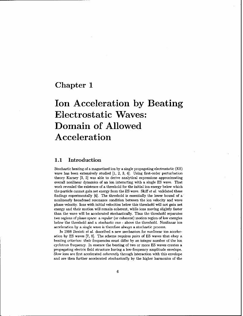
Stochastic heating of a magnetized ion by a single propagating electrostatic (ES)wave has been extensively studied [1, 2, 3, 4]. Using first-order perturbationtheory Karney [3, 5] was able to derive analytical expressions approximatingoverall nonlinear dynamics of an ion interacting with a single ES wave. Thatwork revealed the existence of a threshold for the initial ion energy below whichthe particle cannot gain net energy from the ES wave. Skiff et al. validated thesefindings experimentally [6]. The threshold is essentially the lower bound of anonlinearly broadened resonance condition between the ion velocity and wavephase velocity. Ions with initial velocities below this threshold will not gain netenergy and their motion will remain coherent, while ions moving slightly fasterthan the wave will be accelerated stochastically. Thus the threshold separatestwo regions of phase space: a regular (or coherent) motion region of low energiesbelow the threshold and a stochastic one - above the threshold. Nonlinear ionacceleration by a single wave is therefore always a stochastic process.
In 1998 Benisti et al. described a new mechanism for nonlinear ion acceler-ation by ES waves [7, 81. The scheme requires pairs of ES waves that obey abeating criterion: their frequencies must differ by an integer number of the ioncyclotron frequency. In essence the beating of two or more ES waves creates apropagating electric field structure having a low-frequency amplitude envelope.Slow ions are first accelerated coherently through interaction with this envelopeand are then further accelerated stochastically by the higher harmonics of the
6

FINAL REPORT 9/1/04: ION ACCEL. WITH BEATING WAVES 7
beat wave. Under such conditions the single-wave theory threshold disappearsand regular and stochastic regions of phase space become connected allowingions with arbitrary small initial velocities to obtain high energies through co-herent acceleration followed by stochastic energization. Consequently, this non-linear interaction may result in a more efficient acceleration mechanism than ispossible from the interaction with a single wave. This new acceleration schemehas been advanced as a possible explanation for the ionospheric ion accelerationobserved during the Topaz 3 [9] rocket experiments. An acceleration mechanismthat promises to energize a larger portion of the ion distribution function maybe promising to many applications where the efficiency of ion heating is of primeimportance, such as in spacecraft plasma propulsion.
A preliminary numerical exploration [10] of this mechanism revealed thatthere are many cases for which the beating criterion does not lead to ion ac-celeration. This hinted to the possibility that the criterion is necessary but notsufficient.
In this study we attempt, using analytical and numerical techniques, todefine the necessary and sufficient conditions for the acceleration of the magne-tized ion through nonlinear interaction with a pair of propagating electrostaticwaves. In particular, we use second-order perturbation theory and numericalintegration to analyze the nonlinear dynamics by finding the location of thecritical points [11] of the motion on a Poincar6 cross-section [121. These criticalpoints were not observed in previous studies [7, 8] since they were limited to theanalysis of a single trajectory (i.e. single initial condition) in a given Poincar6cross-section. The location of these critical points allows us to define the initialconditions for the Hamiltonian and the ion's velocity required for a magnetizedion to be energized by a pair of beating waves.
In section 1.2 we overview the analytical formulation of the problem. Inorder to give context to our study we review in section 1.3 the better-knowndynamics of a magnetized ion interacting with a single ES wave. This is followedin section 1.4 by an overview of the fundamental features of the new mechanismthat relies on beating waves. In the remaining sections we seek expressions forthe location of the critical points of the motion which amount to a definition ofthe domains of allowed and forbidden acceleration.
1.2 Analytical Formulation
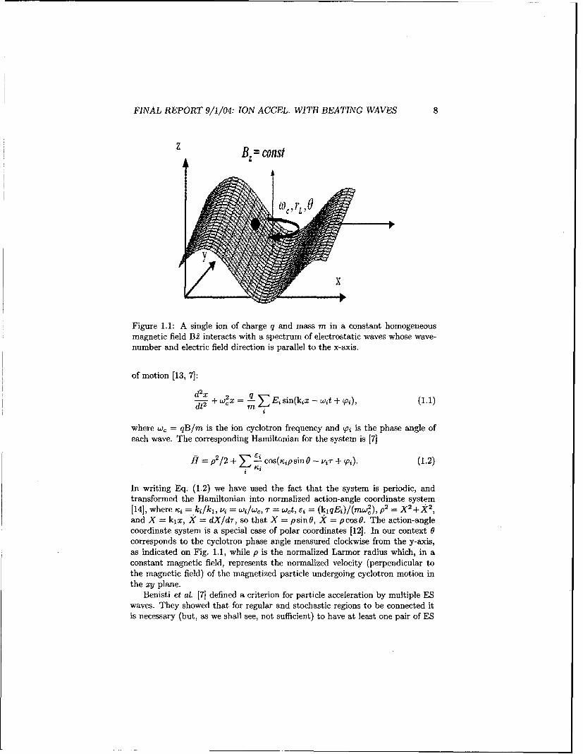
We start by defining the coordinate axis as shown in Fig. 1.1. Here we havea single ion of mass m and charge q in a constant and homogeneous magneticfield, Bi. This ion interacts with a packet of electrostatic waves that propagatein the positive x direction. Since we take the waves to be purely electrostaticthe wave-number ki is parallel to the electric field Ei of each of these waves.The dynamics of the single ion in Fig. 1.1 is described by the following equation
FINAL REPORT 9/1/04: ION ACCEL. WITH BEATING WAVES 8
= const
Figure 1.1: A single ion of charge q and mass m in a constant homogeneousmagnetic field B, interacts with a spectrum of electrostatic waves whose wave-number and electric field direction is parallel to the x-axis.
of motion [13, 7]:
S+Ei sin(kix- (1.1)
where w, = qB/m is the ion cyclotron frequency and Soi is the phase angle ofeach wave. The corresponding Hamiltonian for the system is [7]
f=P2/2±+ ei cos(Kipsin 0 - vi-r + vi). (1.2)
In writing Eq. (1.2) we have used the fact that the system is periodic, andtransformed the Hamiltonian into normalized action-angle coordinate system[14], where Ki = ki/kl, vi = w/wc, -r = wet, e = (kiqEi)/(mw,), p2 =X2 2and X = kx, X = dX/dr-, so that X = psin0, X = pcos0. The action-anglecoordinate system is a special case of polar coordinates [12]. In our context 0corresponds to the cyclotron phase angle measured clockwise from the y-axis,as indicated on Fig. 1.1, while p is the normalized Larmor radius which, in aconstant magnetic field, represents the normalized velocity (perpendicular tothe magnetic field) of the magnetized particle undergoing cyclotron motion inthe xy plane.
Benisti et at. [7] defined a criterion for particle acceleration by multiple ESwaves. They showed that for regular and stochastic regions to be connected itis necessary (but, as we shall see, not sufficient) to have at least one pair of ES

FINAL REPORT 9/1/04: ION ACCEL. WITH BEATING WAVES 9
waves such that
W2 - W1 = nw., (1.3)
where n is an integer. They also report that acceleration is more vigorous forn < 2, therefore for the sake of simplicity, we limit our analysis to the case of asingle pair of beating waves, such that n = 1. In addition, Ref.[7] reports thatthe maximum acceleration is achieved when all waves are of the same amplitude,-=i = e . We also set Ki = rj = K, to simplify our analysis, and since thephase angles, Vi, do not play a fundamental role in this acceleration process [71we set all Vi = 0. With these simplifications the Hamiltonian (1.2) becomes
H = p'/2 + [cos(p sin 0 - ij) + (1.4)
cos(p sin O - vj-r)].
This Hamiltonian represents two coupled oscillators: one is the gyrating ion andthe other corresponds to the beating ES waves. We, therefore, can interpret Eas a coupling parameter between the two oscillators.
Two approaches are taken in this study for analyzing the system above.First, we derive the analytical solution to equation (1.4) by applying a second-order perturbation technique in conjunction with Deprit modified [15, 16] Lietransformations [12, 13], and then compare it with the results of numericalintegration of equation (1.4). To obtain the numerical solution we use the fourth-order symplectic integration algorithm (SIA4) derived by Candy and Rozmus[17] who showed its superiority over fourth order Runge-Kutta algorithm forHamiltonian periodic problems, such as ours.
A convenient way of representing both numerical and analytical solutions isto plot the resulting trajectories on a Poincar6 cross-section [12]. To constructa Poinca6 cross-section from the numerical integration of Eq. (1.4) we plot thepoint intersections of the ion trajectory in three dimensions (p, 0, r) with the p-0plane at specific time intervals. For integer values of v this reduces to plotting pvs. 0 at 7- = 27rj, where j = 0, 1, 2, ... is a non-negative integer. For non-integervalues of v precaution must be taken for proper accounting of intersection points.
Since the magnetic field is constant, the normalized cyclotron radius p is a directmeasure of the perpendicular ion velocity. Therefore Poincar6 cross-sections givedirect visual insight into the acceleration process.
The visual interpretation of Poincar6 cross-sections is straightforward. Ran-dom point distribution corresponds to stochastic motion while regular patterns,such as lines and ellipses, will tell us that the ion dynamics is analytical (orregular). For example, if the wave amplitude, E, is zero, Eqs. (1.1) and (1.4)reduce to a simple harmonic oscillator and for irrational values of V its Poincar6cross-section shows a set of horizontal lines, indicating constant velocity (whichcorresponds to a free ion gyrating in a constant magnetic field). Each of theselines represents an invariant of motion for a given set of initial conditions [12].When the coupling parameter e is not zero, we can treat the ion motion as aperturbation of these invariants.

FINAL REPORT 9/1/04: ION ACCEL. WITH BEATING WAVES 10
The detailed derivation of the analytical solution for a particle interactingwith a single wave can be found in Ref. [5]. However, a more generalized solutionfor multiple waves is obtained [12, 13, 18] through Deprit's modified Lie trans-formation in Refs.[7, 8]. The resulting autonomous Hamiltonian derived fromEq. (1.4) for a non-integer value of v to the second order in the perturbation,E, is
H = E{J,(p) cos(vit) + Jvj(p) cos(vjO)}
+ e2{SN (p) + S'(p)+ S6'i" (p)cos[(vj -i)O]}, (1.5)
where,
1 x-° mJm(p)J'(p)
S (p) = -
= i( 00 mJmp)J~.V.+m'(p) +S6 ~~2p m__z00 V
+ 0 M mJ(P) ji-+m(P)), (1.6)E .'3 - mM=--00
Jm is the Bessel function of the first kind of order m, and JX represents thederivative of the Bessel function with respect to its argument. When vi is aninteger, the summations are performed over all m 7 vi to avoid singularities.When v 0 integer, the first order terms in Eq. (1.5) disappear [7], and theequation becomes more tractable.
The Hamiltonian in Eq. (1.5) is autonomous and therefore itself is an in-variant of motion. Curves of constant H in a Poincar6 cross-section representthe complete analytical solution of the problem to second order. We now wishto compare the Poincar6 cross-sections of the analytical solution to those ob-tained through numerical integration of Eq. (1.4). It should be noted that weshould not expect to see any stochastic behavior on the Poincar6 cross-sectionsobtained from the analytical solution.
As with most phase diagrams, critical points define the dynamics of motion.Since the system is not dissipative we expect to find two types of critical points:elliptic and hyperbolic. As we shall show later, the location of the criticalpoints is the key to determining which initial conditions lead to acceleration ortrapping. The task before us is to find these critical points.
We now explore particle dynamics as a function of wave amplitude andfrequency, and in terms of the location of critical points on the Poincar6 cross-section. Using numerical solutions we will demonstrate that when critical pointsare absent in the regular region of the Poincar6 cross-section (as in the singlewave-particle interaction), the particle will not gain net energy.

FINAL REPORT 9/1/04: ION ACCEL. WITH BEATING WAVES 11
1.3 Single Wave Interaction
70-60- Po=25
50-
40-
30-1/22 0. ..... ....P ~ - v ". ........ ... ..
20 ------------------ * P....--...-.
0-0 I I I
0 400 800 1200 1600T
Figure 1.2: Time evolution of the normalized velocity p for a particle interactingwith a single off-resonance wave (e = 10, v = 24.3). The threshold derived inRef.[5] and given by Eq. (1.7) represents the boundary between the regular andstochastic domains and is shown as a horizontal dashed line. This picture isqualitatively similar to the case of the non-beating waves.
In this section, in order to create a context for our study, we summarizethe results obtained by Karney [5, 3] for the interaction of a magnetized par-ticle with a single electrostatic wave. When the wave frequency is exactly aninteger number of the ion cyclotron frequency it is said to be an on-resonancewave, otherwise it is an off-resonance wave. In both cases Karney found that athreshold given by
p = - VIC, (1.7)
separates the regions of regular and stochastic motion [5, 19], as shown Fig. 1.2,which illustrates for the numerical solution of the equation of the motion (1.1) atypical case (6 = 10, Y = 24.3). Below the threshold, indicated by the horizontaldashed line (p - 20), we observe that the ion motion is regular and we canpredict its behavior well by means of perturbation theory. More importantly,as long as the ion's initial velocity is in that region it is clear that the ionwill not gain net energy from the wave [5]. When the initial velocity is abovethe threshold, the ion moves stochastically and eventually gains net energy, asshown by the upper trajectory in Fig. 1.2. Therefore, in the case of interactionwith a single wave the ion gains energy only chaotically when its initial velocityP0 exceeds the threshold.

FINAL REPORT 9/1/04: ION ACCEL. WITH BEATING WAVES 12
140-
120
10-
80 Accelerated ion60-
40- -...• .pV-1/ Trapped ion
0
0 400 800 1200 1600
Figure 1.3: Time evolution of the normalized velocity p for a particle interactingwith two beating waves (e = 10, vi = 24.3, vj = 25.3). Two particle trajectoriesare shown, one with an ion trapped below p < v - v/E threshold and anotherresulting in an accelerating ion. For both trajectories po are the same but 00are different.
This is an important point and we will contrast it later with the case ofbeating waves where, as we shall see, the two regions of phase space can becomeconnected under some conditions, and a particle with an arbitrarily small initialvelocity in the regular region can be accelerated through the threshold to highvalues of p.
1.4 Multiple Wave Interaction
One of the early investigations of two ES waves interacting with ions was doneby Chia et at. [13, 20] who conducted an analytical study of the interactionto first order in the perturbation and found that for the waves with even-evenor odd-odd combinations of frequencies v, there existed a vertical separatrixallowing "infinite" heating. In 1998 Benisti et a. [7, 8, 9] showed that toobserve particle acceleration through the threshold boundary one needs to useperturbation theory to at least second order. According to their analysis, thenormalized condition for the new acceleration mechanism already given by Eq.(1.3) is
v. - v3 = n, (1.8)
where n is an integer. This amounts to a wave beating condition. By analyzinga single ion trajectory obtained from numerical solutions of Eq. (1.1) Benisti et

FINAL REPORT 9/1/04: ION ACCEL. WITH BEATING WAVES 13
al. showed that as long as condition (1.8) is satisfied the ion will gain significantenergy from the waves.
Subsequently, we performed numerical investigation [101 based on the samesingle trajectory method and found that some ion trajectories did not lead toion acceleration even if condition (1.8) was satisfied, as shown in Fig. 1.3. Weconcluded that to find the necessary and sufficient conditions for ion accelerationwe need to examine the complete Poincar6 cross-section and find the criticalpoints of motion, as will be done in sections 1.5 and 1.6.
We first investigated the case of two electrostatic waves when condition (1.8)does not hold. The picture is qualitatively very similar to that of the single wave-particle interaction shown in Fig. 1.2. Ions with energies below some thresholdmaintain coherent motion and do not gain net energy. This picture can changedrastically if condition (1.8) is satisfied.
As we already mentioned above, the case of the off-resonance beating waves(both vi and v2 are not integers) provides us with much more tractable analyticalexpressions. Consequently, we will focus our attention on such cases. Somequalitative analysis of the on-resonance beating waves is still possible and willbe done in section 1.7.
In Fig. 1.4 we show typical Poincar6 cross-sections obtained by numericalintegration for vl = 24.3 and v2 = 25.3. The panels in this figure illustratethe effect of increasing wave amplitude. The phase diagram consists of tworegions, stochastic and regular, just as for the single wave interaction. However,unlike the single wave-ion interaction, the two regions are "connected". By"connected" we mean that an ion with low initial velocity can undergo firstregular and then stochastic acceleration, reaching high energies.
For low perturbation strength (low values of e) the regular region extends tovalues of p approximately predicted by Eq. (1.7). However, as E is increased theregular region quickly shrinks to the vicinity of the elliptic critical point (desig-nated E on Fig. 1.4.) Notice that the elliptic point is located at PE '- V/2 andOE = 7r. In dimensional quantities the position translates into relation betweenthe ion velocity and the wave phase velocity, vio0 - -0.5w/k. Eventually, asthe wave amplitude is raised above values shown on Fig. 1.4, chaotic motiondominates the phase diagram.
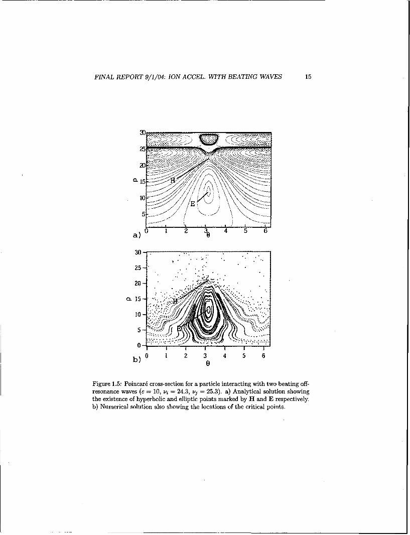
We now gauge how well the second-order perturbation analysis compares tothe numerical solutions. Fig. 1.5 indicates a good degree of agreement betweenthe two. Even though the detailed structure of the regular motion lines is notcaptured with the analytical solution, the latter does predict the position of thelower elliptic (E) as well as the hyperbolic point (H) rather well. On the otherhand, our analytical approach breaks down in the stochastic region, as shouldbe expected. Therefore the critical points shown by the analytical solution tobe at p > 25 in Fig. 1.5 (which can be said to describe a "homoclinic tangle" or"stochastic layer") are in reality covered by the stochastic motion, as shown bythe numerical solution.
However, as described in Ref.[8], even in that region of phase space theoverall ion motion could be approximated by first-order orbits, for small E.

FINAL REPORT 9/1/104: ION ACCEL. WITH BEATING WAVES 14
30-
25-.
CL 15 10a5
0
0 1 2 3 4 5 6
300
20 -.
2.5-
10-
CL 15i'W -
5-
0
0 1 2 3 4 5 6
30-.
25-
20-..
o.15- *
5*.
0 1 2 3 4 5 60
Figure 1.4: Poincar6 cross-sections showing numerical solutions for a particleinteracting with two beating off-resonance waves (vi = 24.3, vj = 25.3). Thestochastic region occupies a greater fraction -of the phase space as the waveamplitude is increased.
FINAL REPORT 9/1/04: ION ACCEL. WITH BEATING WAVES 15
• 15/E
a) O 1 3 4 5 6
30-.
25
2 .. . ..
10 :X - ""
I I I ' 'I I I
b) 0 1 2 3 4 5 60
Figure 1.5: Poincar6 cross-section for a particle interacting with two beating off-resonance waves (E = 10, vi = 24.3, vj = 25.3). a) Analytical solution showingthe existence of hyperbolic and elliptic points marked by H and E respectively.b) Numerical solution also showing the locations of the critical points.

FINAL REPORT 9/1/04: ION ACCEL. WITH BEATING WAVES 16
0.14-
H0.12 -
0.10- Energy Barrier
0.08-
0.06- E
0.04- I I I I I
0 5 10 15 20 25p
Figure 1.6: Analytical Hamiltonian as a function of p at 0 = 7r. The elliptican the hyperbolic points corresponding to the ones shown in Fig. 1.5 are theminimum and the maximum of H. (vi = 24.3, vj = 25.3).
1.5 Topology of the Phase Diagram
As with any phase diagram, each curve on the Poincar6 cross-section correspondsto a given set of initial conditions. In the case of a particle interacting withbeating waves we are mainly concerned with the hyperbolic and elliptic criticalpoints designated H and E respectively on Fig. 1.5. It is clear by tracingtrajectories in Figs. 1.4 and 1.5 that an ion with Hamiltonian lying betweenthe Hamiltonian values corresponding to points E and H does not gain netenergy from the waves i.e. does not reach the stochastic region where it canbe vigorously accelerated. Instead the corresponding phase space trajectoriescirculate around the elliptic critical point E or cover the full range of cyclotronphase angles (0 < 0 < -r) while remaining below H.
Other features of the Poincar6 cross-section in Fig. 1.5 worth mentioning(but not central to our discussion on acceleration) are the two degenerate saddlepoints that can be seen at the intersection of the fourth curve (outward) fromthe elliptic point with the 0-axis and the "primary" (upper) separatrix that isapproximately near the eleventh curve (outward) from the elliptic point.
It is relevant to note in this context that the Hamiltonian of various tra-jectories increases monotonically from the Hamiltonian value at point E to itsvalue at point H, as shown in Fig. 1.6. The figure shows the Hamiltonian asa function of p for 0 = 7r and illustrates that the location of the elliptic andthe hyperbolic points could be found by determining the local minimum and themaximum of H.

FINAL REPORT 9/1/04: ION ACCEL. WITH BEATING WAVES 17
Therefore, for given values of vi and E, the inequality
HE < H(po, Oo) < HH, with po < v - v¼ (1.9)
defines the forbidden acceleration domain, where HE and HH are the Hamilto-nian values for the elliptic (E) and the hyperbolic (H) points, and subscript 0refers to initial conditions. By "forbidden acceleration domain" we mean herethe domain of initial conditions for which an ion cannot reach the stochasticregion of phase space where it can be vigorously energized. All other ion tra-jectories then lie in the allowed acceleration domain of phase space. The ionsin the allowed acceleration domain will be affected by the waves strongly. Therestriction on p0 in Eq. (1.9) is needed because ions with P0 > v - V/e will notbe trapped in the energy barrier between the elliptic and the hyperbolic points(i.e. in the forbidden acceleration domain), as shown in Fig. 1.6.
The "trapping" criterion in Eq. (1.9) given in terms of the Hamiltonianshould be contrasted with the threshold criterion for interaction with a singlewave given by Eq. (1.7). It is clear that unlike the single-wave case, an ion withinitial velocity po below the "threshold" can still be accelerated to high energiesif the corresponding Hamiltonian is outside the range described by Eq. (1.9)
From the point of view of plasma acceleration one would like to limit thenumber of particles trapped in the forbidden acceleration domain (HE < H(po, 00) <HH). The rest of the ions gain much higher energies through first regular (iftheir initial energy is low) and then stochastic acceleration, as shown in Figs.1.4 and 1.5. However, even the trapped particles can escape into the stochasticdomain if we consider a collisional plasma, given that a trapped particle maygain enough energy during a collision to overcome the energy barrier, Fig. 1.6,as we have shown through particle simulations reported in Ref.[21].
1.6 Critical Points
To define the domains of allowed and forbidden acceleration described by Eq. (1.9)we need to find the location of the critical points E and H. We now seek ana-lytical expressions for both.
Since both points are the extrema of the Hamiltonian, that task can beachieved by setting the time derivative of p and 0 to zero simultaneously [12, 11].Utilizing Hamilton's equations of motion in conjunction with Eqs. (1.5) and (1.6)we get
aHp - -0 =e{ViJg,(p)sin(viO) (1.10)
"± vJ,,Jv (p) sin(v39)}
"± 6i(vi - vj)S6"'"(p)sin[(vj - vi)O] = 0,S= aH
5p- = {J', (p) cos(vA0) (1.11)
+ g((p)cos(vj0)}
FINAL REPORT 9/1/04: ION ACCEL. WITH BEATING WAVES 18
+ E2{s, (P) +~'p
+ S61' "(P)cosI(Vi - = 0.
When both wave frequencies are off-resonance (vi, vj 0 integer), the equationsabove simplify because the first-order terms drop out, and we are able to obtainthe position of critical points analytically.
For v 0 integer, the S1'(p) term in Eq. (1.6) could be simplified to analgebraic equation containing only few Bessel functions [13]:
IT
S'(p) = 8sin vi•r
- J-,-i(P)J-(.i-1)(P)]. (1.12)
As a result of this simplification we can reduce the S$"v" (p) term down to
Si ''(p)j = P Sr (p) + PL S (p). (1.13)Vi Vi1
The details of this derivation are given in the appendix. We can thereforeexpress the Hamiltonian (1.5) in terms of the simplified S'i (p) function only,
H= 2{(1 +Pcos[vi- vj]O)S'ki(p)V i
+ (1 + p cos[vi - vj]O)S'i (P) (1.14)Vi
As we will show later in this section our analysis breaks down for small valuesof v. Consequently we take vi > 1, and remembering that n = 1 with p/vj =p/(vi + 1) ,- p/vi(1 - 1/vi. + ...) we can approximate p/li - p/vj. Dropping thesubscripts in S'i (p) we have
H = e2 [ + L Cos((vi - Vj)0] x
[S' (p)+ SVj (P)]. (1.15)
Finally, we substitute Eq. (1.12) for each of the S'i (p) functions. Expressingeverything in terms of vi we get
H ( 2inr + - cosO) (1.16)
[ -
I J'-(P)J-ý-10 + 4'(p)J-(p)
+ Jv+1(P)J-(,,+l)(P) - Jv+2(P)J-(v+2)(P)j,
where we have replaced vi with v.
FINAL REPORT 9/1/04: ION ACCEL. WITH BEATING WAVES 19
We are now ready to find the position of points E and H. From Eq. (1.10)as well as from Figs. 1.4 and 1.5 we see that these points lie at 0 = 7r. Thisreduces equations (1.10) and (1.11) to
-p(1 - P)L(p) = 0, where (1.17)'9P L'
L(p,v) = -J,-_l(p)J-_(,-_)(p) + J,(p)Jg-(p)
+ J.+I(P)J-(,+i)(P) - Jv+ 2 (P)J-(,+ 2)(P).
From Eq. (1.17) we can express p as a function of L(p) and L'(p), where theprime denotes the derivative with respect to p, and arrange the resulting ex-pression as
p 1 L(p, v)- 1or (1.18)v v L'(p, v)'
F(p,v) = p P 1L(p,v)v vvL(p, v) . (1.19)
The first and second roots of Eq. (1.19), PE and PH, for a given value of v,correspond to the locations of the elliptic and hyperbolic points respectively.
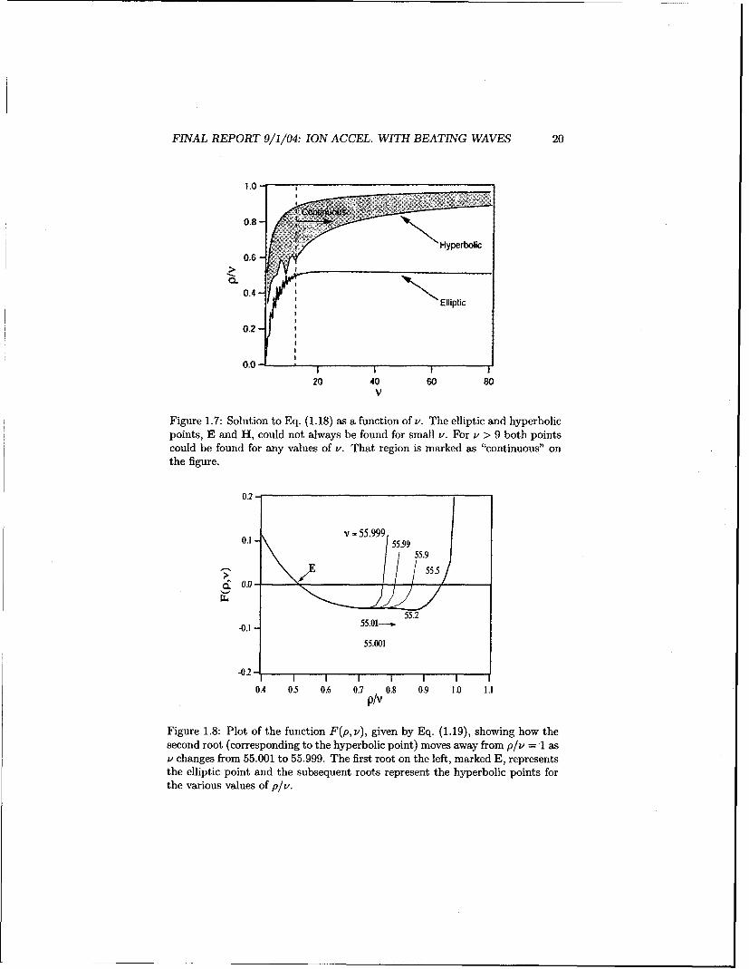
The solution to Eq. (1.18) for a range of v is shown in Fig. 1.7, while theF(p,v) of Eq. (1.19) is plotted as a function of p/v for v c [55.001,55.999] inFig. 1.8. It is now important to discuss the behavior of these solutions.
As we discussed above, we are only considering the cases with v 4 inte-ger. Unfortunately, due to the asymptotic behavior of the Bessel function nearthe "turning point" [22], defined as Ptp = v•(v + 1), the solution approachesdifferent limits as v gets close to an integer from different sides. This peculiarbehavior is demonstrated for the case of v - 55 in Fig. 1.8. Therefore, no simpleanalytical expression could be obtained for the position of the hyperbolic point.Instead, Fig. 1.7 shows a range of solutions for the location of this point. On theother hand, the elliptic point is very well defined. It is seen that for sufficientlylarge values of v the location of the elliptic point, according to our second-orderperturbation analysis is at
PE OE = ir. (1.20)
Although no simple expression could be found for the location of the hyperbolicpoint, we see from Fig. 1.7 that its location asymptotes (at large values of v) toa value of plv - (0.8 - 1.0), therefore we may approximate
PH :- 0.9v, OH = 7- (1.21)
It is also important to mention that because of the asymptotic behavior ofBessel functions, the elliptic and hyperbolic points could not always be foundfor small values of v. For these cases while the expression for the Hamiltonian,Eq. (1.16), is still valid, our analysis of the allowed and forbidden acceleration
FINAL REPORT 9/1/04: ION ACCEL. WITH BEATING WAVES 20
1.0-
Hyperbolic
0.6
0,4.Elliptic
0,0 . ..
20 40 60 80V
Figure 1.7: Solution to Eq. (1.18) as a function of v. The elliptic and hyperbolicpoints, E and H, could not always be found for small v. For Y > 9 both pointscould be found for any values of v. That region is marked as "continuous" onthe figure.
0.2-
0 .I* 1 -v = 5 5.9 9 9 5 5 .9 90.155.99
55.9~. 0.0-
55.01-- 55.2-0.1
55.001
-0.2-
0.4 0,5 0.6 0.7 0.8 0.9 1.0 1.1p/v
Figure 1.8: Plot of the function F(p, v), given by Eq. (1.19), showing how the
second root (corresponding to the hyperbolic point) moves away from p/v = 1 asv changes from 55.001 to 55.999. The first root on the left, marked E, representsthe elliptic point and the subsequent roots represent the hyperbolic points forthe various values of p/v.

FINAL REPORT 9/1/04: ION ACCEL. WITH BEATING WAVES 21
domains does not apply. The range of v for which we could always find bothcritical points is designated as "continuous" in Fig. 1.7.
Another limitation is placed on our analysis by its independence on c inlocating the critical points, as seen from Eq. (1.17). Extensive numerical explo-ration of the weak dependence of the critical point locations on E suggests thefollowing corrections to expressions (1.20) and (1.21), which are reminiscent ofthe c dependence in the single wave interaction [5], Eq. (1.7),
(E2 O eE = 7, (1.22)PE: = 2 '
PH = V - Vp, OH = 7r. (1.23)
The physical interpretation and significance of these two points could beunderstood as follows. Looking back at Fig. 1.1 we see that both points cor-respond to the particles moving 1800 out of phase with the electric field of thewave. We can note from Fig. 1.6 that at the hyperbolic point the ion velocity isVH = -w/k + vt, and the Hamiltonian is at the maximum, while at the ellipticpoint the ion velocity is vE = (-wlk + vt,)/2, and the Hamiltonian is at theminimum. The difference in the Hamiltonian of the two points then forms an"energy barrier", which an ion must overcome to be accelerated by the wave.
Another way to understand the importance of the elliptic point is to realizethat at this point the energy exchange between the ion and the waves is minimumand the situation is equivalent to stable equilibrium for a pendulum. Any smallperturbation from that equilibrium will only cause small oscillations about it.This implies that in the immediate neighborhood of point E the ion energycannot be altered sufficiently to push the ion into the stochastic region, asseen in Fig. 1.5. On the other hand, the hyperbolic point corresponds to theunstable equilibrium of the pendulum and any small perturbation from it willcause significant changes in the ion motion, i.e. escape into the stochastic regionand subsequent vigorous heating.
1.7 Beating Waves (On-Resonance)
When we choose vi and vj to be both on-resonance, the overall behavior becomesmuch more complicated and no simple analytical expression, as in the previoussection, can be found. Fig. 1.9 shows a typical example, the case with E = 10,vi = 24, and vj = 25. One of the major differences with respect to the off-resonance case is that now we have two hyperbolic points which do not lie at0 = Ir. Nevertheless, we could still find their positions by solving equations(1.10) and (1.11) numerically.
The location of the elliptic point is easier to obtain since the first-order termsin Equations (1.10) and (1.11) drop out for 0 = 7r, as in the off-resonance case.Also, Fig. 1.9 shows that the analytical solution exhibits much more complicatedchains of the critical points at large values of p. While in reality these pointsare "inside" the stochastic region, this graphical picture illustrates why theanalytical treatment of the on-resonance case is more challenging. However, we

FINAL REPORT 9/1/04: ION ACCEL. WITH BEATING WAVES 22
note that the locations of both the elliptic and the hyperbolic points even inthis case are very close to those determined by Eqs. (1.6). Indeed, by studyingnumerically the solutions to Eq. (1.4) for both on-resonance and off-resonancecases we conclude that the locations of elliptic and hyperbolic points for bothcases could be well predicted by Eqs. (1.6).
1.8 Summary and Concluding Remarks
The beating criterion (W1 - w2 = nwr) proposed by Benisti et al. [7, 8] canallow a magnetized ion to be energized by a pair of beating electrostatic waves.The importance of this mechanism stems from its ability to accelerate ions witharbitrarily low initial velocity. It has become clear however, (see Fig. 1.3) thatthis criterion is not sufficient for acceleration.
In order to better define the criteria for acceleration we investigated multipleion trajectories (multiple initial conditions) on the same Poincar6 cross-section.This analysis led to the identification of critical points on the phase diagram.Vigorous ion acceleration now can be explained in terms of the location of thesepoints in the region of regular motion. A second-order perturbation analysis ofthe equation of motion allowed us to derive the criterion defining the allowedand forbidden acceleration domains in terms of the location of these points.
According to this analysis, for a pair of beating (vi - v2 = 1), electrostaticwaves interacting nonlinearly with a magnetized ion, significant ion accelerationcan occur as long as the Hamiltonian of the system does not satisfy the following"trapping" criterion
HE < H(po; 0o) < HH, with po < v - ¼/c, (1.24)
(which strictly applies when v >> 1). If the ion's initial conditions do notsatisfy the above trapping criteria, the ion can be accelerated from arbitrarilylow initial velocity through the region of regular motion to the stochastic regionwhere substantial energization can occur.
Regular ion acceleration is a much slower process than stochastic energiza-tion [10]. However, as the wave amplitude is increased, the region of stochasticmotion can extend down to low initial velocities. It is important to note thatthe trapping criterion is in terms of the (initial) Hamiltonian and not just the(initial) velocity (Po).
The necessary (wave-beating) condition stated in Eq. (1.8) along with theavoidance of the trapping criterion stated in Eq. (1.24) represent two necessaryand sufficient conditions for the beating-wave ion acceleration mechanism tooccur.
Finally, it is important to mention that the trapping criterion's independenceof the wave energy e is a consequence of the second-order nature of the analysis.In light of the albeit weak dependence on e in the single-wave criterion in Eq.(1.7), we investigated numerically over a wide range of non-dimensional param-eters (E z 5 - 100, v z 10 - 50) location of the critical points and found that

FINAL REPORT 9/1/04: ION ACCEL. WITH BEATING WAVES 23
l•~~~~ ~~ -.-- . .:! \ , ....... ..
.... .. ...
14/
0. 12\
X /
105
... .. .. . .. ..... ... . . . .. . . . .\' ............. ......... . /
Z8 29 3 31 32 33 34 35 6
300
15-'
"o0 1 2 3 4 5 6a-2)
25too
o 2 3 4 5 6b) 6
Figure 1.9: Poincar6 cross-section for a particle interacting with two beatingon-resonance waves showing a more complicated picture than that of the off-resonance case shown in Fig. 1.5. (c = 10, v. = 24, ' 25). a-) and a-2)
analytical solution. b) numerical solution.
FINAL REPORT 9/1/04: ION ACCEL. WITH BEATING WAVES 24
the same dependence on applies. Therefore, given the locations of the criticalpoints in Eq. (1.6) we can rewrite the trapping criterion in Eq. (1.24) as
H[(v - vle)/2; ir < H(po; Oo) < H(v - v'E; ir),
with P0 < v- /•.
While the above study offers insight into the fundamental problem of a sin-gle ion interacting with two beating waves, the relevance of the mechanism topractical problems involving a plasma rests on resolving a number of issues: 1)the effects of oblique wave propagation, as recently studied in Ref.[23]; 2) theeffects of wave dispersion; 3) the extension to collection of particles and therole of collisions. This last effect was a subject of numerical investigation inRef.[21]. In that work we found that collisional scattering enhances ion ener-gization by providing an escape mechanism for the ions trapped in the forbiddenacceleration domain of phase space.
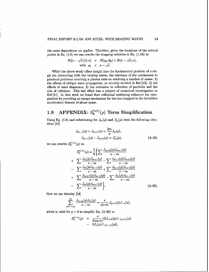
1.9 APPENDIX: Sý"vi(p) Term Simplification
Using Eq. (1.8) and substituting for Jm(p) and J4,(p) with the following iden-tities [22]
J.-i (P) + Jm+i(P) = 2m Jm(p),P
Jm-i(p) - Jm+I(P) = J.'(P), (A-25)
we can rewrite S '6' (p) as
S+ i " .(p)J ) Jm+2 (P)J_+I(P)
+ z Jm(P)Jm+i (P) ZJm-I(P)Jm+2(P)v-rn v-rn
Jm(p)Jm-i(p) + Jm-i(P)Jm- 2 (P)
± z Jm+i(P)Jm- 2 (P) _ Jm(P)Jm-i(P)
- ZJm(p_)Jm+_l(P)} (A-26)
Now we use identity [24]
g J+p(p)JM(p) = .
v-rm sin irvP
which is valid for p > 0 to simplify Eq. (A-26) to
$6"(P = 8 sin 'Tv [2J,+ 2 (p)J-(,+l)(p)
-2J,(p)J-(.,-i)(p)],
FINAL REPORT 9/1/04: ION ACCEL. WITH BEATING WAVES 25
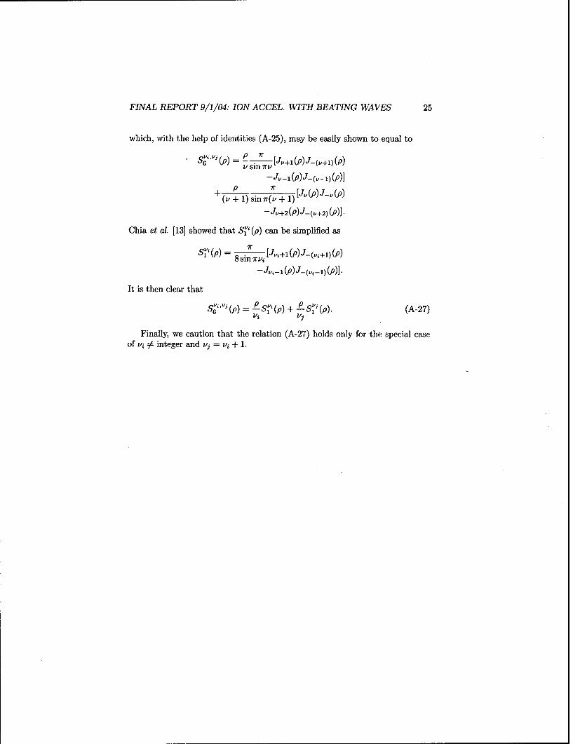
which, with the help of identities (A-25), may be easily shown to equal to
snp irv
-J'- 1 (P)J-(v'-)(P)]
(v + 1) sin 7r(v + 1)[ j(p)j-'(p)-J,,+2(P)J-(.,+2) (P)].
Chia et al. [13] showed that S 'i(p) can be simplified as
S" (p) 8 i [J,+1(P)J-(T,+1)(P)
J-i g- (P) J-(v, -1)(P)]
It is then clear that
Sivj (p)) + ± S (P) (A-27)
Finally, we caution that the relation (A-27) holds only for the special caseof vi 0 integer and vj = vi ± 1.

Chapter 2
Effects of Ion Collisions onIon Acceleration
2.1 Introduction
Acceleration of magnetized ions by beating electrostatic waves (BEW) is a non-linear phenomenon that may be occurring in nature and may have interestingapplications to various problems including spacecraft propulsion. Observationsmade with the Topaz 3 rocket [9] indicated that ions are accelerated, in a regionof natural electrostatic wave activity, in the topside ionosphere to the escapevelocity. A puzzling issue is that initial velocities of these ions are significantlybelow the previously known threshold required for resonant acceleration by elec-trostatic waves. The threshold was derived in the context of ion interaction witha single electrostatic wave (SEW) [3, 5].
Benisti et al. [7, 8] proposed a non-resonant acceleration mechanism thatrelies on nonlinear interaction of an ion with a pair of beating waves. Theyshowed that if the criterion
nWc = W2 - W1, (A-1)
is satisfied between any pair of electrostatic waves, ions can be acceleratedfrom an arbitrary low initial velocity. Equation (A-i) states that the differencebetween the frequencies of the two beating waves W, and W2 should equal to aninteger multiple, n, of the ion cyclotron frequency w,. This is in great contrastwith the well known SEW-ion interaction studied theoretically by Karney et al.[3, 5], Zaslavsky et al. [24, 4], and Chia et al. [13, 20], and experimentally bySkiff et al. [6]. These studies showed that for acceleration to take place ioninitial velocity has to be within a resonance band of the wave velocity. Anotherfundamental understanding obtained from these studies was that the ion motionduring SEW-ion acceleration is always stochastic.
Choueiri and Spektor [10] investigated the beating wave acceleration mech-anism theoretically and found that while Eq. (A-i) is necessary for the accel-
26

FINAL REPORT 9/1/04: ION ACCEL. WITH BEATING WAVES 27
eration to occur, it is not a sufficient condition. Spektor and Choueiri [25]derived and verified the necessary and sufficient conditions for interaction, alsodiscussed in section 2.2. When these conditions are satisfied, an ion with anarbitrary low initial velocity can accelerate through a regular (non-stochastic)motion in the electric field of the beating waves, then reach a threshold abovewhich acceleration continues more vigorously (stochastically).
Since the BEW acceleration can increase the perpendicular velocity of allions, as opposed to only the resonant part of the distribution function, it is ofparticular interest to spacecraft propulsion applications where acceleration orheating efficiency is of prime importance. In order to obtain the first indicationof the existence of this mechanism we have designed and built a dedicatedexperiment using a helicon source and RF antenna to launch pairs of beatingwaves [26].
In order to guide the design of the experiment and help in interpreting itsresults we needed a model of the interaction that more resembles the case of areal plasma than does the single ion model. Such a model should account for theinteraction of the waves with large amount of particles, and most importantlyion-ion collisions. In this study we present such a model based on using MonteCarlo techniques to describe collisions, and solving the equation of motion be-tween collisions. We use the simulation to study parametrically the effects ofion collisions on the heating rate and attainable average energy for both SEWand BEW.
In section 2.2 we review the collisionless model that describes the interac-tion of a single particle with a spectrum of electrostatic waves. We also reviewprevious findings resulting from that model. In section 2.3 we present the nu-merical model that allows tracking a large number of ions and account for afinite collision rate. In section 2.4 we present and discuss the results of our nu-merical investigation, and in section 3.7 we summarize our findings and deducea phenomenological picture that illustrates the fundamental differences betweenBEW and SEW ion acceleration.
2.2 Single Particle Model
A theoretical model for beating electrostatic waves interacting with a singleion is given in [7, 8, 25]. The description, which latter in this chapter is aug-mented with inclusion of collisions and the ability of tracking many ions, isshown schematically in Fig. 2.2. The schematic shows an ion in a constantmagnetic field Bi and electrostatic wave traveling in transverse direction 1.The wave interacts with a gyrating ion causing a change in its Larmor radius.Because the magnetic field is constant, an increase in the Larmor radius di-rectly corresponds to the increase in the ion's perpendicular velocity and thusits kinetic energy. The equation of motion governing the interaction betweena spectrum of propagating electrostatic waves and a single ion can be easily

FINAL REPORT 9/1/04: ION ACCEL. WITH BEATING WAVES 28
Z
Figure 2.1: A single ion of charge q and mass m in a constant homogeneousmagnetic field B; interacts with an electrostatic wave. The wavenumber andelectric field of the wave is parallel to the x-axis.
derived [3, 13]:d2xdt-2- + w2x= Z Ei sin(kix - wit + Voi), (A-2)
where x and t are the coordinate and the time variables, q and m are the chargeand the mass of the ion, w. = qB/m, Ei, ki, wi, and ¢i are the amplitude, wavenumber, frequency and phase of the ith electrostatic wave. While Fig. 2.2 showsa single wave, a similar picture can be drawn for a spectrum of electrostaticwaves traveling in the same direction. It is convenient to normalize the aboveequation and express it in the canonical form [14, 12]:
H= p2 /2 + y: -- cos(Kip sin 0 - vir + 0i), (A-3)
where H is the Hamiltonian of the system, ti = ki/k 1 , vi = wi/we, "r = wet, ei =
(klqEi)/(mw2), p 2 = X 2 + k 2, and X = klx, X = dX/dr, so that X =p sin 0, X = p cos 0. Where 0 is the cyclotron rotation angle measured clockwisefrom the y-axis as shown in Fig. 2.1 , and p is the normalized Larmor radius.Equations (A-2) and (A-3) could be solved numerically with either conventional4th order Runge-Kutta scheme or a symplectic approach. We have used thesymplectic integration method developed by Candy and Rozmus [17] to studythe behavior of a single ion interacting with one or two propagating electrostaticwaves.
We were able to confirm [25] that while a single electrostatic wave producessome ion heating under restricted (resonance) conditions, two beating wavescan result in ion acceleration from arbitrary low initial velocities. We havealso shown that Eq. (A-i) describes the necessary, but not sufficient conditionfor that heating to take place. The necessary and sufficient conditions for ionheating by the beating electrostatic waves are [25]:
nw, = W2 - w1 , (A-4)
H(p;0) = HH > H(p -v-VE-;O=7r), (A-5)

FINAL REPORT 9/1/104: ION ACCEL. WITH BEATING WAVES 29
where HH is the value of the Hamiltonian evaluated at the hyperbolic point asdescribed in Ref.[25] and shown schematically in Fig. 2.2.
The schematic shows the possible acceleration processes. Particle 1 is ac-celerated stochastically in both cases. Particle 2 with initial energy below theSEW resonance threshold (p = v - ,Fe is affected by BEW but is never al-lowed to reach the stochastic region. While particle 3 remains unaffected bythe SEW interaction, it can be effectively accelerated by BEW through regular(non-stochastic) motion that allows it to reach stochastic region, where morerigorous acceleration takes place.
10
0L I
0 1 2 4 5 6
Fiue2.:Pinaecos etin(hsedara)sheai.Thbiur)hw
singl eletrosttic ave (EW) )betinolctrostaic wavese(a EW).

FINAL REPORT 9/1/04: ION ACCEL. WITH BEATING WAVES 30
2.3 Including Collisions
Collisions alter the picture described in the previous section drastically. Withoutcollisions an ion whose initial velocity (Hamiltonian) is below that correspondingto Eq. (A-5), particle 2 in figure 2.2b will never be effectively accelerated by thewaves. However, a collision would instantaneously change that ion's trajectoryand place it in a part of phase place where Eq. (A-5) is satisfied.
In this section we consider ion collisions only. Coulomb ion collisions are ofinterest since they thermalize the heavy species energy and since our main focusis ion heating.
To introduce collisions into our numerical model we follow the classical workof Takizuka and Abe [27]. We model Coulomb collisions as small angle binarycollisions and assume that on a sufficiently small time scale we can uncoupleparticle motion from collisions. Thus our algorithm consists of two parts. Wemove all particles between collisions according to the equation of motion pre-scribed by the single particle collisionless model, Eq. (A-2). We then use theMonte Carlo approach to determine randomly the collision partners and thescattering angles for each collision.
2.3.1 Overall implementation
1. We first choose a time step At smaller than the ion-ion relaxation timecalculated at the initial temperature of the ions.
2. Using a 4 th order Runge-Kutta scheme we then follow each particle in oursimulation for At seconds according to the equation of motion for a singleion, Eq. (A-19).
3. Next we randomly choose a collision partner for each ion.
4. Using Monte Carlo method we then determine the velocity increments forall colliding pairs as described in section 2.3.2. The new velocities are fedback into the Runge-Kutta solver.
5. After each collision, we store the value of the scattering angle E) for eachparticle. We assume that whenever E sin 2 E > 1 the particle has under-gone one ion-ion Coulomb collision. Here the summation is over successivecollisions for a given particle.
2.3.2 Momentum exchange during a collision
We treat Coulomb collisions between ions as a small angle binary elastic scat-tering events [27]. Such collisions preserve energy and momentum.
The relative velocity vector u(u,, uY, u.) for a colliding pair is:
U = Va -Vb, (A-6)
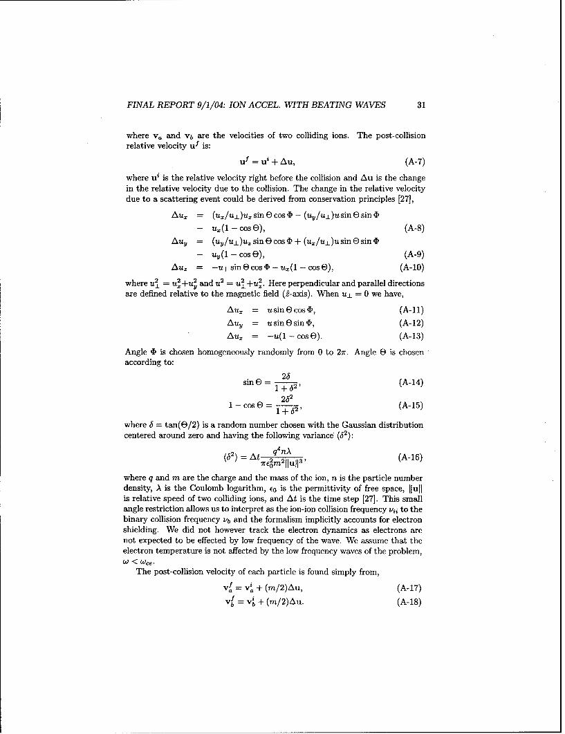
FINAL REPORT 9/1/04: ION ACCEL. WITH BEATING WAVES 31
where va and Vb are the velocities of two colliding ions. The post-collisionrelative velocity uf is:
uf = ui + Au, (A-7)
where ut is the relative velocity right before the collision and Au is the changein the relative velocity due to the collision. The change in the relative velocitydue to a scattering event could be derived from conservation principles [271,
Au, = (u./u±)uzsinEcos• - (uy/u±)usinEsinb
- u,(1 - cos E), (A-8)
Auy = (uv/uL)uz sine cos 4 + (u,/u±)u sine sin D
- uy(1 - cosE), (A-9)
Au, = -u 1 sin E cos (D - u.(1 - cos E)), (A-10)
where u X Y and = u±+uZ. Here perpendicular and parallel directionsare defined relative to the magnetic field (2-axis). When u± = 0 we have,
Au, = usinecos4D, (A-11)
AuY -= usinEsin4i, (A-12)Auz = -u(1 - cos E). (A-13)
Angle 4) is chosen homogeneously randomly from 0 to 27r. Angle E is chosenaccording to:
sin - 1E 2' (A-14)
2321 - cos E) = 2' (A-15)
1 +J2' (-5where 3 = tan(E/2) is a random number chosen with the Gaussian distributioncentered around zero and having the following variance (32):
(32) = q4nA (A-16)(55E = 1t m ll'l
where q and m are the charge and the mass of the ion, n is the particle numberdensity, A is the Coulomb logarithm, E0 is the permittivity of free space, lullis relative speed of two colliding ions, and At is the time step [27]. This smallangle restriction allows us to interpret as the ion-ion collision frequency vii to thebinary collision frequency vb and the formalism implicitly accounts for electronshielding. We did not however track the electron dynamics as electrons arenot expected to be effected by low frequency of the wave. We assume that theelectron temperature is not affected by the low frequency waves of the problem,W < Wce.
The post-collision velocity of each particle is found simply from,
= vf + (m/2)Au, (A-17)
b= v' + (m/2)Au. (A-18)

FINAL REPORT 9/1/04: ION ACCEL. WITH BEATING WAVES 32
2.3.3 Moving the particles
Starting from the Lorentz force equation,
F = mR = q(E + v x B), (A-19)
we can derive equations of motion for a single particle in three dimensions. Inour analysis, the magnetic field is constant ,B = Bi, and the electric field arisesfrom the propagating electrostatic waves, as shown in Fig. 2.1,
+= y+E sin(x - wit), (A-20)i
S---- -, (A-21)
=- 0, (A-22)
so that •, j, and i are the second derivatives with respect to time t, and theother variables are the same as those appearing in equations (A-2) and (A-3). Equations (2.3.3) could be solved numerically using 4 th order Runge-Kuttamethod.
2.4 Simulation
The above model is used to simulated the case of BEW acceleration (c =
10, v, = 24.3, v2 = 25.3 Ki = 1) and compared to those of SEW acceler-ation under similar condition (E = 10, v = 24.3). To visualize the numericalresults we use Poincare cross-sections (p vs. 0 phase diagrams) [12]. We will alsoinvestigate how collisions influence the energy evolution of the entire system.
2.4.1 Phase diagrams
Figure 2.3 follows collisionless evolution of 1000 particles in the plot p vs. 0.Initially we distribute all particles homogeneously over region of the phase spacep < 20. The stochastic heating is observed whenever ions reach the stochasticzone (p > 20), Fig2.2b. Particles with initial conditions lying outside prohibitedzone are accelerated as could be seen from that figure. The points correspondingto unaccelerated particles define a mount-like structure, seen in the last twopanels of Fig. 2.3, which corresponds to prohibited zone shown in figure 2.2b.Figure 2.4 shows the BEW ion acceleration case where the evolution of phasespace points is qualitatively different then the collisionless case illustrated in2.3. Even ions originally in the forbidden acceleration zone are accelerated.
2.4.2 Energy Evolution
Now that we showed that collisions enhance ion heating, we will analyze theenergy evolution of the entire system. In this section we compare the casesof BEW and SEW ion acceleration by beating electrostatic waves and a singleelectrostatic wave.
FINAL REPORT 9/1/04: ION ACCEL. WITH BEATING WAVES 33
100- 100-1
800
01 2 3 A 5 6 0 1 2 3 4 5 6
0 080
60 o-ii-•"r-- "'•-•r '1 •3 4• (01 2 • 4 566
o S
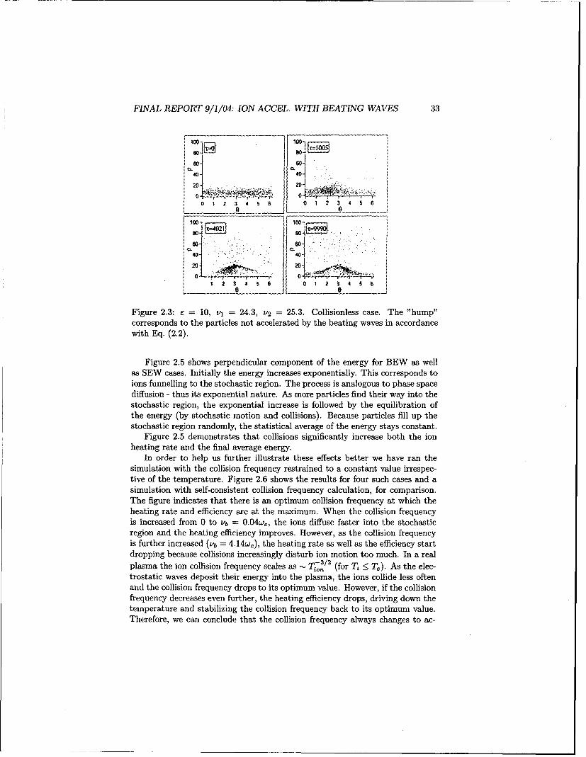
Figure 2.3: E = 10, v, = 24.3, v2 = 25.3. Collisionless case. The "hump"corresponds to the particles not accelerated by the beating waves in accordancewith Eq. (2.2).
Figure 2.5 shows perpendicular component of the energy for BEW as wellas SEW cases. Initially the energy increases exponentially. This corresponds toions funnelling to the stochastic region. The process is analogous to phase spacediffusion - thus its exponential nature. As more particles find their way into thestochastic region, the exponential increase is followed by the equilibration ofthe energy (by stochastic motion and collisions). Because particles fill up thestochastic region randomly, the statistical average of the energy stays constant.
Figure 2.5 demonstrates that collisions significantly increase both the ionheating rate and the final average energy.
In order to help us further illustrate these effects better we have ran thesimulation with the collision frequency restrained to a constant value irrespec-tive of the temperature. Figure 2.6 shows the results for four such cases and asimulation with self-consistent collision frequency calculation, for comparison.The figure indicates that there is an optimum collision frequency at which theheating rate and efficiency are at the maximum. When the collision frequencyis increased from 0 to vb = O.04wc, the ions diffuse faster into the stochasticregion and the heating efficiency improves. However, as the collision frequencyis further increased (vb = 4 .14w.), the heating rate as well as the efficiency startdropping because collisions increasingly disturb ion motion too much. In a realplasma the ion collision frequency scales as - Ti-,/2 (for Ti < Te). As the elec-trostatic waves deposit their energy into the plasma, the ions collide less oftenand the collision frequency drops to its optimum value. However, if the collisionfrequency decreases even further, the heating efficiency drops, driving down thetemperature and stabilizing the collision frequency back to its optimum value.Therefore, we can conclude that the collision frequency always changes to ac-
FINAL REPORT 9/1/04: ION ACCEL. WITH BEATING WAVES 34
0 1 2 3 4 5 6 0 1 , 34 A E,
1. , .20- j"
04.. 0 1
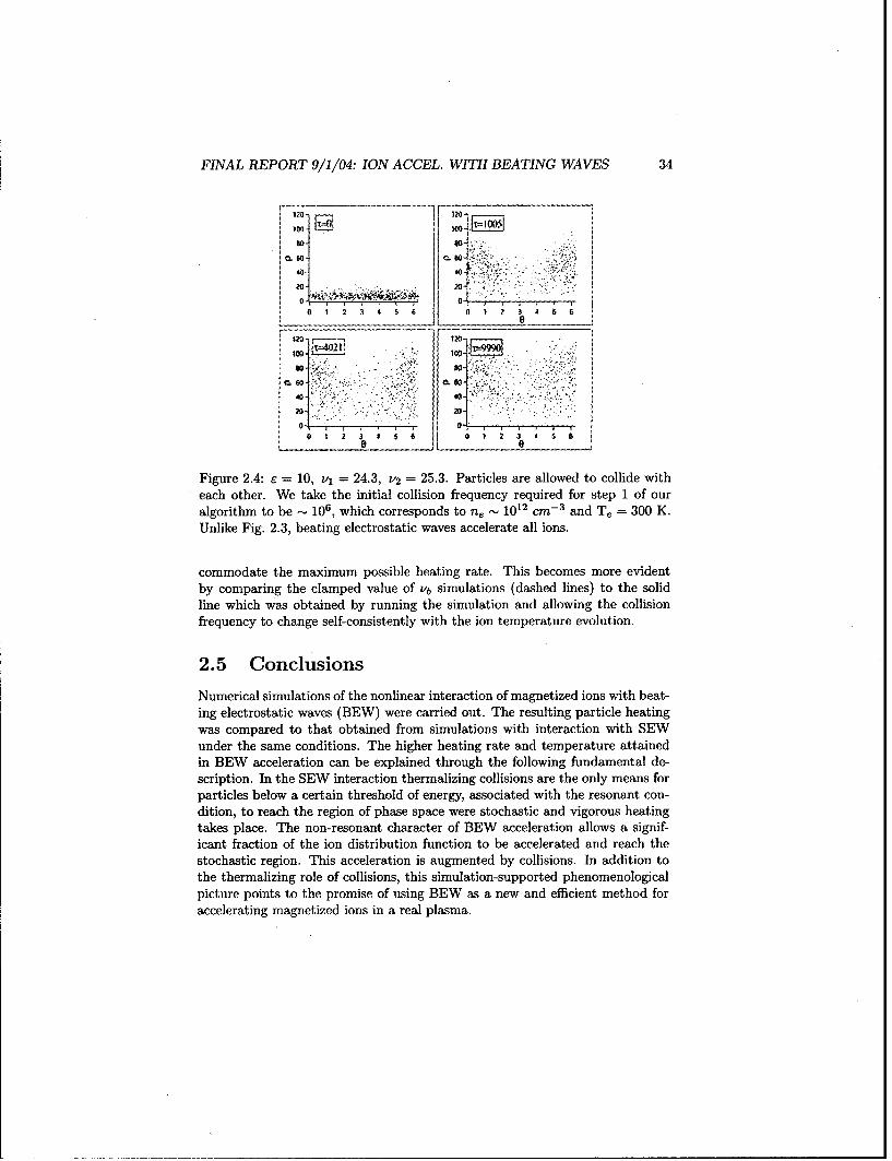
Figure 2.4: e 10, v, 24.3, v2 25.3. Particles are allowed to collide witheach other. We take the initial collision frequency required for step 1 of ouralgorithm to be _ 106, which corresponds to n, _" 1012 cm-' and T. = 300 K.Unlike Fig. 2.3, beating electrostatic waves accelerate all ions.
commodate the maximum possible heating rate. This becomes more evidentby comparing the clamped value of v'b simulations (dashed lines) to the solidline which was obtained by running the simulation and allowing the collisionfrequency to change self-consistently with the ion temperature evolution.
2.5 Conclusions
Numerical simulations of the nonlinear interaction of magnetized ions with beat-ing electrostatic waves (BEW) were carried out. The resulting particle heatingwas compared to that obtained from simulations with interaction with SEWunder the same conditions. The higher heating rate and temperature attainedin BEW acceleration can be explained through the following fundamental de-scription. In the SEW interaction thermalizing collisions are the only means forparticles below a certain threshold of energy, associated with the resonant con-dition, to reach the region of phase space were stochastic and vigorous heatingtakes place. The non-resonant character of BEW acceleration allows a signif-icant fraction of the ion distribution function to be accelerated and reach thestochastic region. This acceleration is augmented by collisions. In addition tothe thermalizing role of collisions, this simulation-supported phenomenologicalpicture points to the promise of using BEW as a new and efficient method foraccelerating magnetized ions in a real plasma.

FINAL REPORT 9/1/04: ION ACCEL. WITH BEATING WAVES 35
80-
- -C~soniss SEW
60-
S40-
.- BEW, no collisions20 - 01#
,'10 SEW, no collisions
0- I I I I I I I
0 2 4 6 8 10 14x10 3
Time (seconds'ca,)
Figure 2.5: Perpendicular energy evolution for 1000 particles interacting withbeating waves. E = 10, v, = 24.3, v2 = 25.3.For comparison we also show theenergy evolution for the single wave-ion interaction. e = 10, v = 24.3.
80-
60o.- --.. .- ";. -:-"
t 40-- b °" " •c
40- ,-v 4.41510 (0
20- '/ ,•/2-7
O - I '1 ! I I I I
0 2 4 6 8 10 14x10 3
Time (seconds'ow)
Figure 2.6: Perpendicular energy evolution for 1000 particles interacting withbeating waves. Dashed lines correspond to the clamped values of collisionfrequency and solid curve represents the self-consistent simulation. C = 10,
v, = 24.3, v 2 = 25.3.
Chapter 3
Beating Waves Experiment:Excitation of Ion CyclotronWaves and Demonstrationof Ion Acceleration
3.1 Introduction
Inductive rf plasma sources, and in particular helicon plasma discharges, are ofinterest in propulsion research because of their high plasma production efficiencyand controllability [28, 29]. Unfortunately, these rf plasma sources produce cold(T2 - 0.1 eV) ions. To achieve high Ihp it is thus necessary to heat these ionsconsiderably.
Various types of electrodeless plasma heating (ion acceleration) provide anefficient way to increase ion temperature. Methods such as the Ion CyclotronRange Heating (ICRH), Lower Hybrid (LH) wave heating, and the current drivehave been suggested for ion heating in fusion devices [30, 31, 32]. The ICRHscheme is also employed in the VASIMR experimental rocket concept [33, 34, 35].In addition, ion heating by various electromagnetic and electrostatic instabilitieshas been observed in the Earth ionosphere [36, 37, 38, 39, 40].
In this chapter we investigate excitation of Electrostatic Ion Cyclotron (EIC)waves that propagate transversely to the external magnetic field. Our previoustheoretical and numerical studies have shown that two beating electrostaticwaves, obeying specific criteria [10, 25, 41, 42], may energize ions very effi-ciently. Such ion energization mechanism can prove to be useful in propulsionapplications.
There is a lack of detailed measurements of EIC wave properties and prop-agation in rf-sustained plasmas. It is with this goal in mind that we investigatethe excitation and propagation of EIC waves across a magnetized rf-sustained
36

FINAL REPORT 9/1/04: ION ACCEL. WITH BEATING WAVES 37
plasma column, and subsequent ion energization by these waves. In the abovesections we have not dealt with ion energization but focused on the excitationand propagation of EIC waves. The energization is demonstrated in the lastsection.
This chapter is organized as follows. In section 3.2 we review previous ex-perimental work on electrostatic wave launching. Then in section 3.3 and 3.4we describe our experimental apparatus and the diagnostics used to detect andstudy the waves. In section 3.5 we analyze the electrostatic waves launched inour apparatus. We summarize our results regarding wave excitation in section3.7. We finally conclude in the last section with the experimental demonstrationof the existence of the new ion acceleration mechanism.
3.2 Review of previous work
Various experiments reported on vigorous ion energization by EIC waves in mag-netized plasmas. However, most of these studies relied on exciting EIC wavesthrough some internal plasma instability. Two typical experimental configura-tions are shown in Fig. 3.1.
In these experiments an electrostatic wave of frequency -w j is excited ei-ther by drawing electron current along the magnetic field to a positively biasedsmall electrode, as shown in Fig. 3.1a, or by creating an electric field perpen-dicular to the external magnetic field, as shown in Fig. 3.lb. In both casessignificant ion energization was observed once the wave was excited [44, 45].Unfortunately in experiments like these, it is impossible to separate the causefrom the effect - the ion energization from the wave generation mechanism. Inaddition the wave frequency cannot be controlled. Thus to investigate ion ener-gization properly one needs to design an experiment where the waves are excitedby some externally controlled antenna.
Four such antenna configurations are shown in Fig. 3.2. Hooke and Barn-abei [46] used capacitively coupled plates, shown in Fig. 3.2a, and Stenzel andGekelman [47] employed a set of wires strung along the magnetic field, as shownin Fig. 3.2b, to launch waves close to the LH resonance. Schmitt launched PureIon Bernstein Waves (PIBW) with a single wire at the center of the plasmacolumn [48], Fig. 3.2c, while Schmitt and Krumm launched Bernstein wavesthrough a mode conversion mechanism with a wire coil wrapped around theplasma column [49], Fig. 3.2d.
Goree et al. [50] and Skiff et al. [6] used electrostatic plate antenna to launcha single electrostatic wave above the ion cyclotron frequency transversely to themagnetic field. Significant stochastic ion energization was reported in the latterexperiment. Since our theoretical and numerical investigations have focused onsimilar frequency range we have adopted this antenna design for our experiment.

FINAL REPORT 9/1/04: ION ACCEL. WITH BEATING WAVES 38
a) 00 l o.
10 TE
SOURCE ONBER CEND CHMER
b)
Sringelecterodes .
Figure 3.1: Typical setup for studying Electrostatic Ion Cyclotron (EIC) wave.a) Used by Motley and D'Angelo [43] to excite current driven EIC. The pictureis taken from Ref. [44]. b) Used by Koepke et aL. to excite inhomogeneousenergy density driven EIC. The picture is taken from Ref. [45].

FINAL REPORT 9/1/04: ION ACCEL. WITH BEATING WAVES 39
b"ba)b) ;T
cd)
Figure 3.2: Various antenna designs for launching waves into a plasma. a)Capacitively coupled plates, and b) a set of wires strung along the magneticfield launch waves close to the LH resonance. c) A single wire at the center ofthe plasma column, and d) a coil wrapped around the plasma column launchBernstein waves.
3.3 Experimental setup
3.3.1 Vacuum Chamber
A schematic of the Beating Wave experimental apparatus (BWX) is shown inFig. 3.3. It consists of two pyrex cylinders placed inside a 0.1 Tesla magnet. Theaxial magnetic field along the centerline is shown in Fig. 3.4. The two curvescorrespond to the ion cyclotron frequency of 10 kHz and 30 kHz in the testsection of the vacuum chamber. The small cylinder is 6 cm in diameter (ID)and 37 cm in length while the large cylinder is 20 cm in diameter (ID) and 46 cmin length. The backplate of the small cylinder is made from molybdenum andis electrically floating to minimize sputtering. The two cylinders are connectedby an electrically floating aluminum plate with a 6 cm concentric hole at thecenter to allow free flow of gas between the cylinders. A uniform fill pressure of1 to 30 mTorr is maintained by a gas feed (Ar or He) at the aluminum endplateof the large cylinder and by a 150 1/s turbo pump with a conductance controllerbacked up by a roughing pump. The system is capable of maintaining a basepressure of 2- 10-6 Torr.
Once the plasma discharge is ignited in the small cylinder, the plasma prop-agates along the magnetic field lines, which are parallel to the axis of the cylin-ders, into the large chamber where the wave-launching and plasma-energizationexperiments are conducted.

FINAL REPORT 9/1/104: ION ACCEL. WITH BEATING WAVES 40
Cutout Magnet housing: Aluminum Plate:W=30cm- OD= 50.2cm 00=27cmH =l10cm L~ L59 cm 5/8" 5.4 cm 3.2 cmOffset =4.5 cm
Aluminum Plate Rail:------ --00=10c W=1.cm
OD3/18c" 1 L=76.8 cm OD 5/4'3/8* 1 1ý Us H3.18 cm
Pyrex Cylinder:,IOD 12
00=7cm __________
[D=6cm 4 -L=37cm -- a--gm--ir- Magnetc Fiel------------------------------
-------- LnmiProbe
L__............_-------_--______.- PlateAntenna
Helicon Antenna
* ..- -- Pyrex Cylinder::~: * 0=22cm
3.8cm 7.6c 7cm m -[ L 7cm- L=46 cm
~4.1 cm~ 3.4cm 3.4 cm 2A4cm -Magnet
Coils
Figure 3.3: The drawing of the BWX experimental apparatus.
800-
600
0 5 10 15 20 25 30 35 40 45 50 55z (cm)
Figure 3.4: The axial magnetic field (B.) along the centerline of the magnet.The ion cyclotron frequency is relatively constant within the test portion of thelarge chamber where the electrostatic waves are launched.
FINAL REPORT 9/1/04: ION ACCEL. WITH BEATING WAVES 41
16x10'2 ?
II I
I I 7 W
42 4Radius (cm)
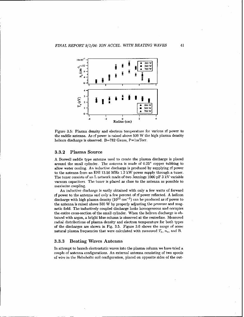
Figure 3.5: Plasma density and electron temperature for various rf power tothe saddle antenna. As rf power is raised above 500 W the high plasma densityhelicon discharge is observed. B=782 Gauss, P=lmTorr.
3.3.2 Plasma Source
A Boswell saddle type antenna used to create the plasma discharge is placedaround the small cylinder. The antenna is made of 0.25" copper tubbing toallow water cooling. An inductive discharge is produced by supplying rf powerto the antenna from an ENI 13.56 MHz 1.2 kW power supply through a tuner.The tuner consists of an L network made of two Jennings 1000 pF 3 kV variablevacuum capacitors. The tuner is placed as close to the antenna as possible tomaximize coupling.
An inductive discharge is easily obtained with only a few watts of forwardrf power to the antenna and only a few percent of rf power reflected. A helicondischarge with high plasma density (1013 cm- 3 ) can be produced as rf power tothe antenna is raised above 500 W by properly adjusting the pressure and mag-netic field. The inductively coupled discharge looks homogeneous and occupiesthe entire cross-section of the small cylinder. When the helicon discharge is ob-tained with argon, a bright blue column is observed at the centerline. Measuredradial distributions of plasma density and electron temperature for both typesof the discharges are shown in Fig. 3.5. Figure 3.6 shows the range of somenatural plasma frequencies that were calculated with measured Te, ne, and B.
3.3.3 Beating Waves Antenna
In attempt to launch electrostatic waves into the plasma column we have tried acouple of antenna configurations. An external antenna consisting of two spoolsof wire in the Helmholtz coil configuration, placed on opposite sides of the out-
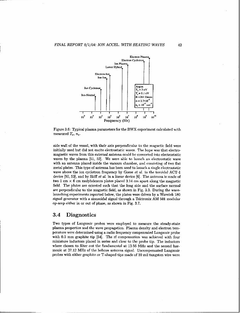
FINAL REPORT 9/1/04: ION ACCEL. WITH BEATING WAVES 42
Electron PlasmaElectron Cyclotron
Ion PlasmaLower Hybri
Electron-IonIon-Ion
[ArgonIon Cyclotron = 3eV
IT,= 30.VIon-Neutral B = 0.1 eV
B =261 Gaussac = 2.7-;j1074
n= 10 cm 3
2 4 I 6 7 a 9 IS
10 10 10 10l 10o 10o 1 o' l 10o0
Frequency (Hz)
Figure 3.6: Typical plasma parameters for the BWX experiment calculated withmeasured Te, ne.
side wall of the vessel, with their axis perpendicular to the magnetic field wereinitially used but did not excite electrostatic waves. The hope was that electro-magnetic waves from this external antenna could be converted into electrostaticwaves by the plasma [51, 52]. We were able to launch an electrostatic wavewith an antenna placed inside the vacuum chamber, and consisting of two flatmetal plates. This type of antenna has been used to launch a single electrostaticwave above the ion cyclotron frequency by Coree et al. in the toroidal ACT-1device [50, 531, and by Skiff et al. in a linear device [6]. The antenna is made oftwo 1 cm x 6 cm molybdenum plates placed 3.14 cm apart along the magneticfield. The plates are oriented such that the long side and the surface normalare perpendicular to the magnetic field, as shown in Fig. 3.3. During the wave-launching experiments reported below, the plates were driven by a Wavetek 180signal generator with a sinusoidal signal through a Tektronix AM 501 modularop-amp either in or out of phase, as shown in Fig. 3.7.
3.4 Diagnostics
Two types of Langmuir probes were employed to measure the steady-stateplasma properties and the wave propagation. Plasma density and electron tem-perature were determined using a radio frequency compensated Langinuir probewith 0.5 mm graphite tip [54]. The rf compensation was achieved with fourminiature inductors placed in series and close to the probe tip. The inductorswhere chosen to filter out the fundamental at 13.56 MHz and the second har-monic at 27.12 MHz of the helicon antenna signal. Uncompensated Langmuirprobes with either graphite or T-shaped tips made of 10 mil tungsten wire were

FINAL REPORT 9/1/04: ION ACCEL. WITH BEATING WAVES 43
In-Phase Out-of-P baseH
H
Cc=2 1iF
I --
*-------7--------I
IkO 9k.l
frIO1-300 kHz + G=10LRI •u, - 150onMax: 50 mA, +/- 40 V
Figure 3.7: The circuit diagram for launching a single electrostatic wave intothe plasma column. The two antenna plates can be driven in or out of phase.
In-Phase 9 Out-of-Phase
L-J[ ------------- U
• f-10-300 kHz "
f610-300OkHz ' r combineRout = 50 Q rcmie
Figure 3.8: To launch a pair of beating waves the impedance between the twosignal sources and the amplifier has to be matched through a power combiner.

FINAL REPORT 9/1/04: ION ACCEL. WITH BEATING WAVES 44
used to detect the wave and investigate its dispersion.Instead of the Laframboise analysis [55] of the Langmuir probe I-V charac-
teristic we used an empirical floating potential method specifically developed byChen et al. [56] to determine T, and n, with rf-compensated Langmuir probesin helicon-sustained plasmas similar to ours.
3.5 Wave launching
The circuit used to launch a single electrostatic wave into the plasma columnis shown in Fig. 3.7. The sinusoidal signal (10-300 kHz) from a Wavetek 180signal generator is amplified with gain of 10 by a Tektronix AM 501 modularoperational amplifier (Rout -- 150 f2, ±40 V, 50 mA Max.). To drive the platesin phase the signal is sent to both plates. A coupling capacitor (C. = 2iF) canbe used, as indicated in Fig. 3.7, to allow both plates to float with respect tothe plasma potential. To drive the plates out of phase the antenna is connectedthrough a 1:1 transformer.
The launching of a pair of beating waves into the plasma is accomplished bycombining the output from two signal sources. This is achieved by mixing thelow-power signals coming out from two Wavetek signal generators and sendingthe combined output to an amplifier, as demonstrated in Fig. 3.8. The outputimpedance of the signal generators and the input impedance of the amplifier is50 Q2. To make sure that the signal of one of the signal generators is not distortedby the other, we needed to match the impedance of the entire circuit. A powercombiner consisting of a 100 D resistor and a tapped inductor in parallel providegood matching between the signal generators and the amplifier.
To ensure that the waves are launched into the plasma efficiently we alsoneeded to maintain a good antenna-plasma coupling. Different amount of poweris delivered to the antenna plates depending on the impedance mismatch be-tween the driving antenna circuit and the plasma. Plasma impedance varieswith the plasma density, i.e. with rf power delivered to the helicon antenna,and the fill-up pressure. For a given pressure the power to the antenna platesand the efficiency of the electrostatic wave launching can be correlated to thehelicon antenna power.
In order to investigate the wave launching conditions we conducted the fol-lowing experiment. The signal generator and the op-amp in Fig. 3.7 were set toproduce a 30-Volt sinusoidal signal (w = 70 kHz) with no plasma. A magnetizedargon plasma with ne = 109 - 1013 cm- 3 and fci = 30 kHz was produced by thehelicon antenna with the chamber back filled to 1 mTorr. Measuring the platesvoltage and current simultaneously we were able to determine the impedanceand the power delivered to the antenna plates as a function of rf power deliv-ered to the helicon antenna. A Langmuir probe inserted into the plasma columnmeasured the amplitude of the launched waves.
We found that for the in-phase configuration the maximum power to theantenna plates is delivered when rf power is 175-200 W, as shown in Fig. 3.9a and3.9b. The amplitude of the Langmuir probe signal is a complicated function of rf

FINAL REPORT 9/1/04: ION ACCEL. WITH BEATING WAVES 45
400 -
a 300 Zi
C 200 q
100 - a13-1,
-~20-& 1-D -- -[3- fa -0- D:&IA. -A, Antenna Power (W)
1.0 A r-o
• ' Fundamental I. 1o' .1 Vo.0..0.
< 05 a.....,. Harmonic ... • ...
30.0 :0. 0- -
a) 100 200 300 400 500
RF Power (watts)
•"300 -•z .iz'
cd 2001200 U
0 G"-° o-E- z-B- G -0-1 o-E- o j:.~2.0
d 2.0"] .. Antenna Power (W)
1. .E " Fundamental ."
I I I I
b) 100 200 300 400 500
RF Power (watts)
400
200 7 - .M 0J- U
&-200 Z, E""-400 "
Antenna Power (W)1.5,
= 1.0 -- "-
< 035 2 Harmonqc A. -A-
I __T
C) 100 200 300 400 500RF Power (watts)
Figure 3.9: The amplitude of the launched wave as well as the impedance and
the power delivered to the antenna plates are shown as functions of the rf powerto the helicon antenna. The real and imaginary components of the antenna
impedance are designated by Z, and Zi respectively. The fundamental as wellas the second harmonic of the launched waves are measured with a Langmuirprobe. a) Both plates are driven in phase (without the coupling capacitor). b)Both plates are driven in phase (with a coupling capacitor connected in series
with the antenna, Fig. 3.7). c) The plates are driven out of phase.
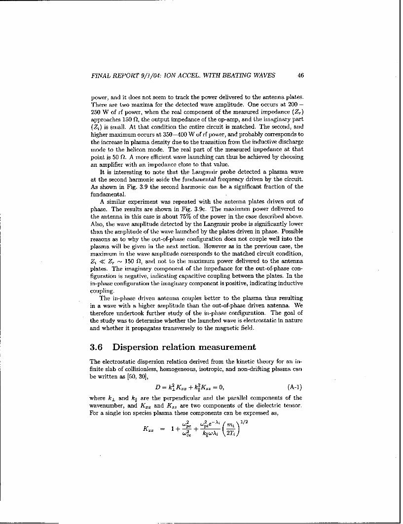
FINAL REPORT 9/1/04: ION ACCEL. WITH BEATING WAVES 46
power, and it does not seem to track the power delivered to the antenna plates.There are two maxima for the detected wave amplitude. One occurs at 200 -250 W of rf power, when the real component of the measured impedance (Zr)approaches 150 Q2, the output impedance of the op-amp, and the imaginary part(Zi) is small. At that condition the entire circuit is matched. The second, andhigher maximum occurs at 350 -400 W of rf power, and probably corresponds tothe increase in plasma density due to the transition from the inductive dischargemode to the helicon mode. The real part of the measured impedance at thatpoint is 50 Q. A more efficient wave launching can thus be achieved by choosingan amplifier with an impedance close to that value.
It is interesting to note that the Langmuir probe detected a plasma waveat the second harmonic aside the fundamental frequency driven by the circuit.As shown in Fig. 3.9 the second harmonic can be a significant fraction of thefundamental.
A similar experiment was repeated with the antenna plates driven out ofphase. The results are shown in Fig. 3.9c. The maximum power delivered tothe antenna in this case is about 75% of the power in the case described above.Also, the wave amplitude detected by the Langmuir probe is significantly lowerthan the amplitude of the wave launched by the plates driven in phase. Possiblereasons as to why the out-of-phase configuration does not couple well into theplasma will be given in the next section. However as in the previous case, themaximum in the wave amplitude corresponds to the matched circuit condition,Zi <K Zr - 150 Q, and not to the maximum power delivered to the antennaplates. The imaginary component of the impedance for the out-of-phase con-figuration is negative, indicating capacitive coupling between the plates. In thein-phase configuration the imaginary component is positive, indicating inductivecoupling.
The in-phase driven antenna couples better to the plasma thus resultingin a wave with a higher amplitude than the out-of-phase driven antenna. Wetherefore undertook further study of the in-phase configuration. The goal ofthe study was to determine whether the launched wave is electrostatic in natureand whether it propagates transversely to the magnetic field.
3.6 Dispersion relation measurement
The electrostatic dispersion relation derived from the kinetic theory for an in-finite slab of collisionless, homogeneous, isotropic, and non-drifting plasma canbe written as [50, 30],
D = k K22 + k K2 2 = 0, (A-1)
where k± and kll are the perpendicular and the parallel components of thewavenumber, and K. 2 and K_. are two components of the dielectric tensor.For a single ion species plasma these components can be expressed as,
+W2 e+W2i -A. ( i 1/2
W~c k11woAi 2Ti

FINAL REPORT 9/1/04: ION ACCEL. WITH BEATING WAVES 47
+C00
n=-oo
2= 1+2we me
k1±k 2TI
where In is the modified Bessel function, A3 k2 Tj/MjW2, Z(Cn) is the plasmadispersion function [57], and Cn = (w - nwj)(mj/2Tj)'/ 2/kj1 , with j = e,i. InEqs. (A-2)Eq:Kzz we assumed that w «< fe and Ae < 1.
To launch an electrostatic ion cyclotron (EIC) wave above the ion cyclotronfrequency the following conditions must also be satisfied [501,
wpi > Wci, Ti •_T5e,
(2Tj/m,)1/2 << W/kj1 < (2Te/me)1/ 2 .
In our experiment we have T. = 3 eV, Ti = 0.1 eV, B = 261 Gauss, w =
30 - 180 kHz, and All - 46 cm, therefore the above inequalities are satisfied.Here we assumed that the parallel wavelength is determined by the extent of thelarge glass cylinder where the waves are launched. By measuring the parallelcomponent of the wavenumber with two axially separated Langmuir probeswe have confirmed that the parallel wavenumber is - 46 cm. The numerical
solution of Eq. (A-i) for the plasma parameters in our experiment is representedin Fig. 3.10.
Theoretical curves can be subdivided into two types according to their slopes.One curve extending from k 1 = 0 to 2 cm- 1 has a positive slope. This curverepresents the forward branch of the EIC dispersion relation since its groupvelocity (aw/8k) is in the same direction as its phase velocity (wik). On theother hand, curves extending from k± = 1 to 6 cm- 1 have negative slopes. Thecurves correspond to cyclotron harmonics of the backward branch of the EICdispersion relation, since their group velocity has the opposite sign of the phasevelocity. The pass-band of each of these backward branches is narrow, and
therefore we do not expect to see any of the backward mode waves propagatingin our experiment.
The slope of the forward branch of the EIC dispersion is sensitive to theelectron temperature, while the backward branch is sensitive to the ion tem-perature. Thus comparing the experimentally obtained dispersion relation tothe theoretical expression provides a good check of the species temperatures.While the ion temperature was not measured, the electron temperature inferredby the slope of the experimental dispersion relation, Te = 2.75 eV, is in goodagreement with the values measured independently with the rf-compensatedLangmuir probe, shown in Fig. 35.
As was mentioned above, the theoretical dispersion relation given by Eq.(A-i) was derived for an idealized plasma. Some plasma parameters of our
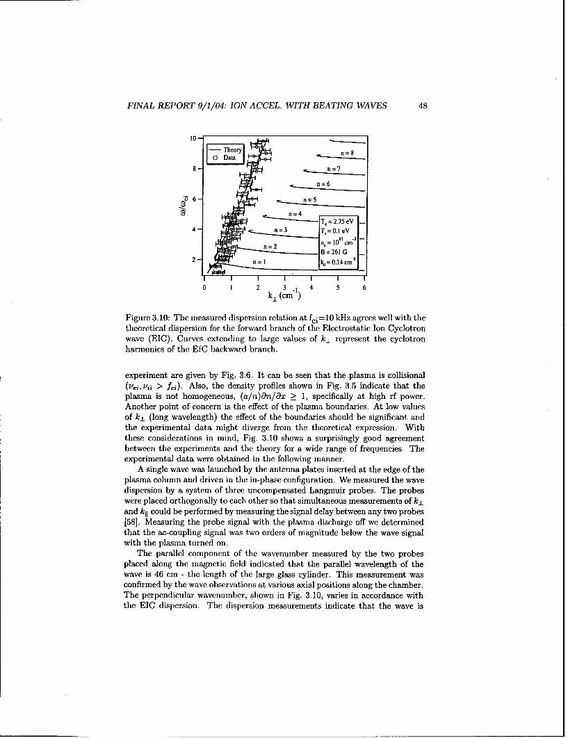
FINAL REPORT 9/1/04: ION ACCEL. WITH BEATING WAVES 48
10-
n=8
8-=7
Z n=6
n=4
4- Tj._=.0..1.=
n = 2 n,= -10 1 cm '
::: B =261G2- n= I ku = 0.14 cm-1
0 1 2 k 3 -1 54k±(cm)
Figure 3.10: The measured dispersion relation at fci=10 kHz agrees well with thetheoretical dispersion for the forward branch of the Electrostatic Ion Cyclotronwave (EIC). Curves extending to large values of k±L represent the cyclotronharmonics of the EIC backward branch.
experiment are given by Fig. 3.6. It can be seen that the plasma is collisional(vej, vii > f.::). Also, the density profiles shown in Fig. 3.5 indicate that theplasma is not homogeneous, (a/n)an/ax _> 1, specifically at high rf power.Another point of concern is the effect of the plasma boundaries. At low valuesof k, (long wavelength) the effect of the boundaries should be significant andthe experimental data might diverge from the theoretical expression. Withthese considerations in mind, Fig. 3.10 shows a surprisingly good agreementbetween the experiments and the theory for a wide range of frequencies. Theexperimental data were obtained in the following manner.
A single wave was launched by the antenna plates inserted at the edge of theplasma column and driven in the in-phase configuration. We measured the wavedispersion by a system of three uncompensated Langrnuir probes. The probeswere placed orthogonally to each other so that simultaneous measurements of k_±and kll could be performed by measuring the signal delay between any two probes[581. Measuring the probe signal with the plasma discharge off we determinedthat the ac-coupling signal was two orders of magnitude below the wave signalwith the plasma turned on.
The parallel component of the wavenumber measured by the two probesplaced along the magnetic field indicated that the parallel wavelength of thewave is 46 cm - the length of the large glass cylinder. This measurement wasconfirmed by the wave observations at various axial positions along the chamber.The perpendicular wavenumber, shown in Fig. 3.10, varies in accordance withthe EIC dispersion. The dispersion measurements indicate that the wave is
FINAL REPORT 9/1/04: ION ACCEL. WITH BEATING WAVES 49
propagating at the angle of 820 to 860 with respect to the magnetic field. Boththe fundamental and the second harmonic components of the signal were usedto construct the experimental dispersion relation shown in Fig. 3.10.
Driving the plates of the antenna out of phase, we expected the parallelwavelength to be 6.28 cm - twice the spacing between the plates. This howeverwas not the case. The measured parallel wavelength was on the order of thechamber length. The measurements of the perpendicular wavelength were notconsistent with the EIC dispersion relation. It is likely that the wave was affectedby the ion Landau damping since w/k11 - Vthi.
3.7 Conclusions regarding ES Wave Excitation
We reported.on the excitation and propagation of an Electrostatic Ion Cyclotron(EIC) wave launched by a two-plate antenna into a magnetized argon plasma.We described in detail the circuity necessary to drive the antenna in the in- andout-of-phase configuration.
We found that the antenna driven in phase couples better to the plasma andexcites higher amplitude waves than the plates driven out of phase.
In addition, we determined that the wave amplitude can be optimized bycarefully choosing the right plasma parameters and building a matched drivingcircuit.
The antenna driven in phase excites a wave with All = 46 cm - the length ofthe portion of the vacuum chamber where the waves are launched. The perpen-dicular component of the wavenumber varies according to the EIC dispersionrelation and is in good agreement with the forward branch of the theoreticaldispersion relation despite the simplifying assumption of a collisionless, mag-netized, homogeneous, isotropic, and infinite plasma slab. We found that EICwaves launched at frequencies between wj and 10wd propagate with little damp-ing at an angle between 82' and 860 with respect to the magnetic field.
Multiple EIC waves required for our ongoing beating waves studies [10, 25,26, 21, 42] can also be easily launched by the plates antenna with two or moresignal generators by means of a power combiner.
3.8 Demonstration of Ion Acceleration
After the success in launching the waves, we proceeded to measure the effectsof the beating waves on ion acceleration to provide the first test for the ex-istence of the new ion acceleration mechanism. The goal was to measure theion's perpendicular enregy (equivalently velocity or temperature) and observeif ion acceleration (or equivalently heating) occurs when a pair of beating ioncyclotron waves are launched. In order to do this measurement we developed,using funds from a recent DURIP grant, a dedicated state-of-the-art Laser In-duced Fluorescence (LIF) diagnostic system (shown in Fig. (3.11)) that allows
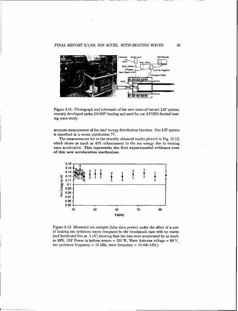
FINAL REPORT 9/1/04: ION ACCEL. WITH BEATING WAVES 50
CaMpirft Diode LAWc Cwillosewql
Figure 3.11: Photograph and schematic of the new state-of-the-art LIF system,recently developed under DURIP funding and used for our AFOSR-funded beat-ing wave study.
accurate measurement of the ions' energy distribution function. Our LIF systemis described in a recent publication ??.
The measurements led to the recently obtained results plotted in Fig. (3.12)which shows as much as 40% enhancement to the ion energy due to beatingwave acceleration. This represents the first experimental evidence everof this new acceleration mechanism.
0.150.140.13
S_ 0.11-S0.1
-0.080,07-
0.060.05
10 30 50 70 90
f(kHz)
Figure 3.12: Measured ion energies (blue data points) under the effect of a pairof beating ion cyclotron waves compared to the benchmark case with no waves(red horizontal line at .1 eV) showing that the ions were accelerated by as muchas 40%. (RF Power in helicon source = 250 W, Wave Antenna voltage - 60 V,ion cyclotron frequency = 10 kHz, wave frequency = 10-100 kHz.)
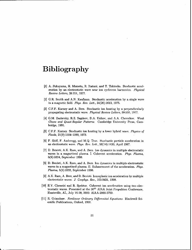
Bibliography
[1] A. Fukuyama, H. Mometa, R. Itatani, and T. Takizuka. Stochastic accel-eration by an electrostatic wave near ion cyclotron harmonics. PhysicalReview Letters, 38:701, 1977.
[2] G.R. Smith and A.N. Kaufman. Stochastic acceleration by a single wavein a magnetic field. Phys. Rev. Lett., 34(26):1613, 1975.
[3] C.F.F. Karney and A. Bers. Stochastic ion heating by a perpendicularlypropagating electrostatic wave. Physical Review Letters, 39:550, 1977.
[4] G.M. Zaslavsky, R.Z. Sagdeev, D.A. Usikov, and A.A. Chernikov. WeakChaos and Quasi-Regular Patterns. Cambridge University Press, Cam-bridge, 1991.
[5] C.F.F. Karney. Stochastic ion heating by a lower hybrid wave. Physics ofFluids, 21(9):1584-1599, 1978.
[61 F. Skiff, F. Anderegg, and M.Q. Tran. Stochastic particle acceleration inan electrostatic wave. Phys. Rev. Lett., 58(14):1430, April 1987.
[7] D. Benisti, A.K. Ram, and A. Bers. Ion dynamics in multiple electrostaticwaves in a magnetized plasma. I. Coherent acceleration. Phys. Plasma,5(9):3224, September 1998.
[8] D. Benisti, A.K. Ram, and A. Bers. Ion dynamics in multiple electrostaticwaves in a magnetized plasma. II. Enhancement of the acceleration. Phys.Plasma, 5(9):3233, September 1998.
[9] A.K. Ram, A. Bers, and D. Benisti. Ionospheric ion acceleration by multipleelectrostatic waves. J. Geophys. Res., 103:9431, 1998.
[10] E.Y. Choueiri and R. Spektor. Coherent ion acceleration using two elec-trostatic waves. Presented at the 3 6th AIAA Joint Propulsion Conference,Huntsville, AL, July 16-20, 2000. AIAA-2000-3759.
[11] R. Grimshaw. Nonlinear Ordinary Differential Equations. Blackwell Sci-entific Publications, Oxford, 1990.
51

FINAL REPORT 9/1/04: ION ACCEL. WITH BEATING WAVES 52
[121 A.J. Lichtenberg and M.A. Lieberman. Regular and Chaotic Motion.Addison-Wesley, Cambridge, MA, 1983.
[13] Ping-Kun Chia, L. Schmitz, and R.W. Conn. Stochastic ion behaviorin subharmonic and superharmonic electrostatic waves. Phys. Plasmas,3(5):1545, May 1996.
[14] H. Goldstein. Classical Mechanics. Addison-Wesley, Cambridge, MA, 1951.
[15] A. Deprit. Celest. Mech., 1:12, 1969.
[16] J.R. Cary. Phys. Rep., 79:129, 1981.
[17] R. Candy and W. Rozmus. A symplectic integration algorithm for separablehamiltonian functions. J. Comp. Phys., 92:230, 1991.
[18] R. Candy and W. Rozmus. Rational resonances in a wave driven linearoscillator. Physica D, 52:267, 1991.
[19] D. Benisti, A.K. Ram, and A. Bers. Lower bound in energy for chaoticdynamics of ions. Phys. Lett. A, 233:209, August 1997.
[20] Ping-Kun Chia, L. Schmitz, and R.W. Conn. Effect of elastic scattering
on stochastic ion heating by electrostatic waves. Phys. Plasmas, 3(5):1569,May 1996.
[21] R. Spektor and E.Y. Choueiri. Effects of ion collisions on ion accelerationby beating electrostaticwaves. Presented at the 2 8th International ElectricPropulsion Conference (IEPC), Toulouse, France March 17-21, 2003. IEPC-03-65.
[22] G.N. Watson. A Treatise on the Theory of Bessel Functions. CambridgeUniversity Press, Cambridge, 2 edition, 1962.
[23] D.J. Strozzi, A.K. Ram, and A. Bers. Coherent acceleration of magnetizedions by electrostatic waves with arbitrary wavenumbers. Phys. Plasmas,
10(7):2722-2731, March 2003.
[24] G.M. Zaslavsky, R.Z. Sagdeev, D.A. Usikov, and A. A. Chernikov. Minimalchaos, stochastic webs, and structures of quasicrystal symmetry. Usp. Fiz.Nauk, 156(193-251):887, October 1988.
[25] R. Spektor and E.Y. Choueiri. Ion acceleration by beating electrostat-icwaves: Criteria for regular and stochastic acceleration. Presented at the271h International Electric Propulsion Conference (IEPC), Pasadena, Cal-ifornia October 14-19, 2001. IEPC-01-209.
[26] R. Spektor and E.Y. Choueiri. Design of an experiment for study-ing ion acceleration by beating waves. Presented at the 3 8 th
AIAA/ASME/SAE/ASEE Joint Propulsion Conference (JPC), Indianapo-lis, Indiana, July 7-10 , 2002.

FINAL REPORT 9/1/04: ION ACCEL. WITH BEATING WAVES 53
[27] T. Takizuka and H. Abe. A binary collision model for plasma simulationwith a particle code. J. Comp. Phys., 25:205-219, 1977.
[281 R. Boswell and F.F. Chen. Helicons - the past decade. IEEE Trans. PlasmaSci., 25(6):1245, December 1997.
[29] R. Boswell and F.F. Chen. Helicons - the early years. IEEE Trans. PlasmaSci., 25(6):1229, December 1997.
[30] T.H. Stix. Waves in Plasmas. Springer-Verlag, New York, 1992.
[31] D.G. Swanson. Plasma Waves. Academic Press, Boston, 1989.
[32] N. J. Fisch. Confining a tokamak plasma with rf-driven currents. Phys.Rev.Lett., 41(13):873, September 1978.
[33] E.A. Bering III, M. Brukhardt, F.R. Chang-Diaz, V. Jacobson J.P. Squire,R.D. Bengtson, J.N. Gibson, and T.Glover. Experimental studies of theexhaust plasma of the vasimr engine. Presented at the 4 0 nd AerospaceSciences Meeting, Reno, Nevada January ,14-17 2002, AIAA 2002-0345.
[34] D.G. Chavers and F.R. Chang-Diaz. Momentum flux measuring instru-ment for neutral and charged particle flows. Rev. Sci.Instrum, 73(10):3500,October 2002.
[35] F.R. Chang-Diaz, J.P. Squire, T.Glover, A.J. Petro, E.A. Bering III, F.W.Baity, R.H. Goulding, M.D. Carter, R.D. Bengtson, and B.N. Breizman.The vasimr engine: Project status and recent accomplishments. Presentedat the 4 2,d Aerospace Sciences Meeting, Reno, Nevada January ,5-8 2004,AIAA 2004-0149.
[36] E.G. Shelley, R.D. Sharp, and R.G. Johnson. Satellite observations of anionospheric acceleration mechanism. J. Geophys. Res., 3(11):654, 1976.
[37] Mozer F.S., C.W. Carlson, M.K. Hudson, R.B Torbert, B. Parady, andJ. Yatteau. Observations of peired electrostatic shocks in the polar mag-netosphere. Phys. Rev. Lett., 38(6):292, 1977.
[38] A.G. Gielmetti, R.G. Johnson, R.D. Sharp, and E.G. Shelley. The letitudi-nal, diurnal, and altitudinal distributions of upward flowing energetic ionsof ionospheric origin. Geophys. Res. Lett., 5(1):59, 1978.
[39] P.M. Kintner, M.C. Kelley, R.D. Sharp, A.G. Ghielmetti, M. Temerin,C. Cattell, P.F. Mizera, and J.F. Fennell. Simultaneous observations ofenergetic (key) upstreaming and electrostatic hydrogen cycotron waves. J.Geophys. Res., 84(A12):7201, 1979.
[40] P. Satyanarayana, P.K. Chaturvedi, M.J. Keskinen, J.D. Huba, and S.L.Ossakow. Theory of the current-driven ion cyclotron instability in thebottomside ionosphere. J. Geophys. Res., 90(A12):12,209, 1985.
FINAL REPORT 9/1/04: ION ACCEL. WITH BEATING WAVES 54
[41] R. Spektor and E. Y. Choueiri. Ion acceleration by beating electrostaticwaves: Domain of allowed acceleration. Physical Review, E, 69(4):ArticleNo. 046402, 2004.
[42] R. Spektor and E.Y. Choueiri. Ion acceleration by beating electrostat-icwaves: Domain of allowed acceleration. Phys.Rev.E, 69(4):046402, April2004.
[43] R.W. Motley and N. D'Angelo. Excitation of electrostatic plasma oscilla-tions near ion cyclotron frequency. Phys. Fluids., 6(2):296, February 1963.
[44] D.M. Suszcynsky, S.L. Cartier, R.L. Merline, and N. D'Angelo. A labora-tory study of collisional electrostatic ion cyclotron waves. J. Geophys. Res.,91(A12):13,729, December 1986.
[45] D.N. Walker, , W.E. Amatucci, G. Ganguli, J.A. Antoniades, J.H. Bowles,D. Duncan, V. Gavrishchaka, and M.E. Koepke. Perpendicular ion heatingby velocity-shear-driven waves. Geoph.Res. Lett., 24(10):1187, May 1997.
[46] W.M.Hooke and S.Bernabei. Direct observation of waves propagating nearthe lower-hybrid-resonance frequency. Phys.Rev.Lett., 28(7):407, February1972.
[47] R.L.Stenzel and W.Gekelman. Electrostatic waves near the lower hybridfrequency. Phys.Rev. A, 11(6):2057, June 1975.
[48] J.P.M. Schmitt. Dispersion and cyclotron damping of pure ion bernsteinwaves. Phys.Rev.Lett., 31(16):982, October 1973.
[49] J.P.M. Schmitt and P. Krumm. Mode conversion and plasma column res-onances in the ion-cyclotron harmonic range. Phys.Rev.Lett., 37(12):753,September 1976.
[50] J. Goree, M. Ono, and L. K. Wong. Observation of the backward electro-static ion-cyclotron wave. Phys. Fluids, 28(9):2845, September 1985.
[51] J.L. Kline. Resonant ion heating in a helicon plasma. Ms, West VirginiaUniversity, 1998.
[52] J. Kline, E. Scime, P.A. Keiter, M.M. Balkey, and R.F. Boivin. Ion heat-ing in the helix helicon plasma source. Phys.Plasmas, 6(12):4767-4772,December 1999.
[53] G.A. Goree. The backward electrostatic ion-cyclotron wave, fast wave cur-rent drive, and fir laser scattering. Ph.d, Princeton University, 1985.
[54] R. Sudit and F. F. Chen. Rf compensated probes for high-density dis-charges. Plasma Sources Sci. Technol, 3:162-168, 1994.
[55] J.G.Laframboise. Technical Report 100, University of Toronto, Institutefor Aerospace Studies, 1966. Document No. AD634596.
FINAL REPORT 9/1/04: ION ACCEL. WITH BEATING WAVES 55
[56] F.F.Chen andJ.D. Evans and D.Arnush. A floating potential method for. measuring ion density. Phys.Plasas, 9(4):1449, April 2002.
[571 B.D. Fried and S.D. Conte. The plasma dispersion function ; the Hilberttransform of the Gaussian. Academic Press, New York, 1961.
[58] D.E. Smith, E.J. Powers, and G.S. Cladwell. Fast-fourier-transformspectral-analysis tecniques as a plasma fluctuation diagnostic tool. IEEETrans. Plasma Sci., PS-1:261, December 1974.

Impact Statement
The revised budget represents about two-thirds the original budget. Therefore, the scopeof the work will be adjusted as follows.
The original plan was to explore the use of three different layered materials: bismuthtelluride, bismuth selenide, and molybdenum diselenide. However, in view of thereduced budget, we will concentrate on the first and last as the first two are quite similar.I do not think this will seriously affect the scientific understanding of nanocomposites weexpect from this study.