Final Remedial Design - United States Army · 2013-02-05 · I Preface This remedial design...
68
Prepared for: Contract Number W91236-07-D-0012 Delivery Order Number CY01 Louisville District April 2012 Final Remedial Design Former Lockbourne Air Force Base Landfill Columbus, Ohio FUDS Property Number G05 OH0007 Project Number G05 OH000703
Transcript of Final Remedial Design - United States Army · 2013-02-05 · I Preface This remedial design...

Prepared for:
Contract Number W91236-07-D-0012Delivery Order Number CY01
Louisville District
April 2012
Final Remedial DesignFormer Lockbourne Air Force Base Landfill Columbus, OhioFUDS Property Number G05 OH0007Project Number G05 OH000703

Former Lockbourne Air Force Base Landfill April 2012
STATEMENT OF TECHNICAL REVIEW
Former Lockbourne Air Force Base Landfill
Final Remedial Design
The CH2M HILL Team has completed the technical review of the submittal of the Former Lockbourne Air Force Base Landfill Final Remedial Design. Notice is hereby given that an independent technical review has been conducted that is appropriate to the level of risk and complexity inherent in the project. During the independent technical review, compliance with established policy principles and procedures, utilizing justified and valid assumptions, was verified. This included review of assumptions; methods, procedures and material used in analyses; the appropriateness of data used and level of data obtained; and reasonableness of the results including whether the product meets the customer’s needs consistent with the law and existing USACE policy.
Technical Reviewer Signature Date of Review
Colleen Reilly 22 April 2012
Project Manager ITR Leader
Tiffany Swoveland Chapman Colleen Reilly


I
Preface
This remedial design presents the details for conducting the remedial action for the former Lockbourne Air Force Base Landfill, Columbus, Franklin County, Ohio. The report was prepared by CH2MHILL in accordance with U.S. Army Corps of Engineer Contract No. W91236-07-D-0012 under Delivery Order No. CY01. This document comprises a basis of design, construction schedule, design calculations, design drawings, technical specifications, cost estimate, draft construction quality assurance/quality control plan, green and sustainable remediation report, compliance plan, and the long-term management strategy.

B a s i s o f D e s i g n
Remedial Design: Former Lockbourne Air Force Base Landfill
FUDS Property Number G05 OH0007 Project Number G05 OH000703
Prepared for
U.S. Army Corps of Engineers Louisville District
Contract Number W91236-07-D-0012 Delivery Order Number CY01
April 2012

ES022411142701MKE I
Contents
Preface .................................................................................................................................................... i Acronyms and Abbreviations .......................................................................................................... v 1. Introduction ......................................................................................................................... 1-1
1.1 Purpose and Scope .................................................................................................... 1-1 1.2 Schedule for Landfill Cover Construction ............................................................. 1-1
2. Project Background ............................................................................................................ 2-1 2.1 Existing Site Conditions ............................................................................................ 2-1
2.1.1 Site Topography ............................................................................................. 2-1 2.1.2 Drainage .......................................................................................................... 2-2 2.1.3 Geology ............................................................................................................ 2-2 2.1.4 Hydrogeology ................................................................................................. 2-2 2.1.5 Wetlands .......................................................................................................... 2-3 2.1.6 Climate ............................................................................................................. 2-4 2.1.7 Groundwater and Surface Water Use ......................................................... 2-4
2.2 Previous Site Studies ................................................................................................. 2-5 2.2.1 Supplemental Site Investigation (2011) ....................................................... 2-5 2.2.2 Additional Site Investigation (2008) ............................................................ 2-5
3. Summary of Selected Remedy and Performance Standards ...................................... 3-1 3.1 Selected Remedy ........................................................................................................ 3-1 3.2 Remedial Design Performance Standards .............................................................. 3-2
3.2.1 Landfill Cover ................................................................................................. 3-2 3.2.2 Surface Water Management .......................................................................... 3-2 3.2.3 Groundwater Monitoring ............................................................................. 3-3 3.2.4 Landfill Gas Monitoring ................................................................................ 3-3 3.2.5 Institutional Controls ..................................................................................... 3-3
4. Basis of Design .................................................................................................................... 4-1 4.1 Work Planning ........................................................................................................... 4-1 4.2 Mobilization................................................................................................................ 4-1 4.3 Site Layout, Access, and Security ............................................................................ 4-2
4.3.1 Site Layout and Access .................................................................................. 4-2 4.3.2 Site Security ..................................................................................................... 4-2
4.4 Site Preparation .......................................................................................................... 4-2 4.4.1 Survey .............................................................................................................. 4-2 4.4.2 Utility Locate ................................................................................................... 4-2 4.4.3 Monitoring Well Abandonment ................................................................... 4-3 4.4.4 Clearing and Grubbing .................................................................................. 4-3
4.5 Construction Surface Water Management ............................................................. 4-3 4.5.1 Erosion and Sediment Control Measures ................................................... 4-3 4.5.2 Erosion and Sediment Control Inspections During Construction .......... 4-4 4.5.3 Erosion and Sediment Control Maintenance During Construction ........ 4-4
4.6 Current Landfill Conditions ..................................................................................... 4-5 4.7 Volume of Waste ........................................................................................................ 4-6

BASIS OF DESIGN
II ES022411142701MKE
4.7.1 Waste Excavation Area 1 .............................................................................. 4-6 4.7.2 Waste Excavation Area 2 .............................................................................. 4-6 4.7.3 Waste Excavation Area 3 .............................................................................. 4-7 4.7.4 Waste Excavation Area 4 .............................................................................. 4-7 4.7.5 Waste Excavation Area 5 .............................................................................. 4-7 4.7.6 Waste Excavation Area 6 .............................................................................. 4-8
4.8 Contact Water Management .................................................................................... 4-8 4.9 Waste Consolidation and Backfill ........................................................................... 4-8
4.9.1 Waste Consolidation ..................................................................................... 4-8 4.9.2 Soil Sampling .................................................................................................. 4-9 4.9.3 Select Fill ......................................................................................................... 4-9 4.9.4 Landfill Cover Section ................................................................................... 4-9
4.10 Cover System Design .............................................................................................. 4-11 4.10.1 Slope Stability ............................................................................................... 4-11 4.10.2 Settlement ..................................................................................................... 4-11 4.10.3 Soil Cover Loss ............................................................................................. 4-13
4.11 Passive Vents ........................................................................................................... 4-14 4.12 Seep Prevention Trench .......................................................................................... 4-15 4.13 Post-Construction Surface Water Management .................................................. 4-15
4.13.1 Erosion and Sediment Control Measures ................................................. 4-15 4.13.2 Surface Water Management ....................................................................... 4-16 4.13.3 Post-Construction Erosion and Sediment Control Inspections ............ 4-17 4.13.4 Post-Construction Erosion and Sediment Control Maintenance ......... 4-17
4.14 Post-Construction Survey ...................................................................................... 4-17 4.15 Site Restoration ........................................................................................................ 4-17 4.16 Reporting .................................................................................................................. 4-17 4.17 Demobilization ........................................................................................................ 4-18 4.18 Institutional Controls .............................................................................................. 4-18 4.19 Long-Term Management ....................................................................................... 4-18
5. Construction Documents .................................................................................................. 5-1 5.1 Design Drawings ....................................................................................................... 5-1 5.2 Technical Specifications ............................................................................................ 5-1
6. Green and Sustainable Design Elements ...................................................................... 6-1 6.1 Strategic Level GSR Elements .................................................................................. 6-1 6.2 Remedial Design Level GSR Elements ................................................................... 6-2 6.3 Green and Sustainable Remediation Report ......................................................... 6-3
7. Compliance Plan ................................................................................................................ 7-1 8. Remedial Action Construction Plan ............................................................................... 8-1
8.1 Schedule ...................................................................................................................... 8-1 8.2 Preconstruction Activities ........................................................................................ 8-1
8.2.1 Planning .......................................................................................................... 8-1 8.2.2 Utility Locate .................................................................................................. 8-2 8.2.3 Surveying ........................................................................................................ 8-2
8.3 Mobilization ............................................................................................................... 8-3 8.4 Site Preparation ......................................................................................................... 8-3 8.5 Waste Excavation and Consolidation ..................................................................... 8-4 8.6 Soil Sampling ............................................................................................................. 8-4

CONTENTS
ES022411142701MKE III
8.7 Site Grading and Backfill .......................................................................................... 8-4 8.8 Soil Cover Construction ............................................................................................ 8-4 8.9 Seep Prevention Trench ............................................................................................ 8-4 8.10 Passive Gas Vents ...................................................................................................... 8-5 8.11 Site Restoration .......................................................................................................... 8-5
8.11.1 Waste Excavation and Borrow Source Area ............................................... 8-5 8.11.2 Soil Cover ........................................................................................................ 8-5 8.11.3 Wetlands and Water Bodies .......................................................................... 8-5
8.12 Monitoring Well Installation and Groundwater Sampling ................................. 8-5 8.13 Post-Construction Survey and Reporting .............................................................. 8-5 8.14 Demobilization ........................................................................................................... 8-6
9. Cost Estimate ....................................................................................................................... 9-1 10 Quality Assurance / Quality Control ............................................................................ 10-1 11. References .......................................................................................................................... 11-1 Appendices
A Construction Schedule B Design Calculations
B.1 Landfill Gas Generation Calculations B.2 Volume Calculations B.3 Slope Stability B.4 Settlement Calculations B.5 Soil Loss Calculations B.6 Surface Water Calculations B.7 Seep Prevention Trench Calculations
C Design Drawings D Technical Specifications E Cost Estimate [USACE internal use only] F Construction Quality Assurance/Quality Control Plan G Green and Sustainable Remediation Report H Long-Term Management Strategy I AEP Easement Documentation J Test Pit Technical Memorandum
Tables
2-1 Wetlands within the Site..................................................................................................... 2-3 4-1 Summary of Material Properties for Slope Stability Analysis .................................... 4-12 4-2 Summary of Results for Slope Stability Analysis .......................................................... 4-12 4-3 Universal Soil Loss Equation Values .............................................................................. 4-13 7-1 Summary of ARARs ............................................................................................................ 7-2 7-2 ARAR Compliance Evaluation Matrix ............................................................................. 7-3 7-3 RD Guidance Evaluation Matrix ....................................................................................... 7-4

ES022411142701MKE V
Acronyms and Abbreviations
AASHSTO American Association of State Highway and Transportation Officials AEP American Electric Power AFB Air Force Base AOC Area of Concern ARARs Applicable or Relevant and Appropriate Requirement ASTM American Society for Testing and Materials BOD basis of design bgs below ground surface BMPs best management practice CFR Code of Federal Regulations COCs constituents of concern DoD Department of Defense ESC erosion and sediment control GSR green and sustainable remediation HDPE high density polyethylene IDA intermediate depth aquifer K hydraulic conductivity LTM long-term management OAC Ohio Administrative Code Ohio EPA Ohio Environmental Protection Agency PCBs polychlorinated biphenyls PVC polyvinyl chloride QA/QC quality assurance/quality control RCRA Resource Conservation and Recovery Act RD remedial design UWBZ upper water-bearing zone USACE U.S. Army Corps of Engineers USEPA U.S. Environmental Protection Agency

1. Introduction

ES022411142701MKE 1-1
SECTION 1
Introduction
This basis of design (BOD) presents the remedial design (RD) elements and design criteria for the selected remedy at Area of Concern (AOC) 1 and AOC 2 at the former Lockbourne Air Force Base (AFB) Landfill in Columbus, Franklin County, east of the village of Lockbourne, Ohio. The Department of Defense (DoD) used the site to dispose of waste from the former AFB. The Decision Document (CH2M HILL 2012) identifies the remedy for the site.
1.1 Purpose and Scope The U.S. Army Corps of Engineers (USACE), in coordination with the Ohio Environmental Protection Agency (Ohio EPA), chose a remedy for both AOCs in accordance with the Comprehensive Environmental Response, Compensation, and Liability Act, as amended in 1986 by the Superfund Amendments and Reauthorization Act, and the National Oil and Hazardous Substances Pollution Contingency Plan. The selected remedy for AOC 1 is the presumptive remedy for landfills. The containment presumptive remedy consists of waste consolidation, construction of a soil cover, long-term management (LTM), and institutional controls. The selected remedy for AOC 2 is implementation of an institutional control that will be implemented through the conveyance of an environmental covenant.
The purpose of this report is to present the RD elements for the selected remedies, which are presented in Section 3. These elements include a summary of the project background, site characteristics, and landfill cover performance standards; RD components, such as description, remedial action construction schedule (Appendix A), design calculations (Appendix B), design drawings (Appendix C), technical specifications (Appendix D), cost estimate (Appendix E), Construction Quality Assurance/Quality Control (QA/QC) Plan (Appendix F); Green and Sustainable Remediation (GSR) Report (Appendix G); and the preliminary framework of the LTM strategy (Appendix H). The cost estimate was prepared for the USACE and is not provided because of remedial action procurement activities.
1.2 Schedule for Landfill Cover Construction The USACE plans to complete remedial construction procurement activities based on available funding. Remedial action construction will commence after procurement and planning activities are complete. Appendix A contains an example construction schedule with the general construction tasks anticipated for this type of project. The construction start date shown in the schedule is based on the anticipated award date of the remedial action contract.

2. Project Background

ES022411142701MKE 2-1
SECTION 2
Project Background
The site was used to dispose of wastes generated at the former Lockbourne AFB from 1951 to 1979. The types of waste disposed of included general trash from base housing and other administrative buildings, construction and demolition debris, and lime sludge from the base water treatment plant. The landfill may also have received pesticides and herbicides, ammunition, airplane parts, and hazardous materials. Wastes reportedly were buried in trenches up to 10 feet below ground surface (bgs) and on the ground surface (Law Engineering and Environmental Services 1995; CH2M HILL 2009; 2011a).
Between 1986 and 2011, investigations were conducted to evaluate environmental contamination. During the investigations, landfill gas, soil, sediment, surface water, seep, and groundwater samples were collected. Some investigations included taking geophysical measurements and digging test pits to determine extent of buried waste at the site. As a result of the investigations, contaminants such as polynuclear aromatic hydrocarbons, semivolatile organic compounds, polychlorinated biphenyls (PCBs), dioxins/furans, and metals were determined to be constituents of concern (COCs) in soil, surface water, sediment, or groundwater.
The site is divided into two investigation areas (Sheet 3 of the design drawings). AOC 1 covers roughly 105 acres on the western half of the site where waste disposal occurred. AOC 2 covers roughly 40 acres on the eastern side of the site. Although there is scattered inert debris at AOC 2 (for example, construction and demolition debris), historical investigations indicate AOC 2 was not used for waste disposal. However, because of the shift in boundary between AOC 1 and AOC 2, there is an incidental amount of waste in AOC 2 that will be addressed under AOC 1. The waste in AOC 2 will be gathered and placed in the landfill at AOC 1.
2.1 Existing Site Conditions This section describes current site features, including topography, drainage, geology, hydrogeology, wetlands, climate, and groundwater and surface water use.
2.1.1 Site Topography The site is located in the Central Lowland Province, which is characterized by low relief and elevation, in the western half of Ohio. The Central Lowland Province consists of the Lake Plain and Till Plains physiographic sections. The site lies within the Till Plains section of the Central Lowland Province. The Till Plains are extensive areas with a flat to slightly undulating terrain (National Cooperative Soil Survey 1980).
Scrub and old field vegetation occur in the northwestern corner of the site and in small areas in the southern half. The land surface is uneven, with land elevation ranging from 700 to 735 feet above mean sea level. Water sometimes collects in the low areas after rainfall.

BASIS OF DESIGN
2-2 ES022411142701MKE
2.1.2 Drainage Surface water from the site drains to a man-made perimeter ditch along the eastern and western boundaries of the site and ultimately to Big Walnut Creek. Big Walnut Creek lies 0.75 mile (at its closest point) west of the site. The part of the drainage ditch southeast of the site is referred to as the East Ditch, the part to the southwest as the West Ditch. The West Ditch contains a reinforced concrete structure formerly used by the Lockbourne AFB as a flow control structure for surface water runoff (Engineering Science 1992).
The greater Columbus area lies in the center of the state and in the drainage area of the Ohio River. The site is within the Scioto River watershed. The Scioto and Olentangy rivers flow through the city. The elevation of the City of Columbus averages 833 feet above mean sea level, and the average elevation of the site is 725 feet.
2.1.3 Geology The site is characterized by roughly 200 feet of Pleistocene glacial drift that fills a preglacial bedrock valley (Noble and Korsok 1995). Shales of the Ohio and Olentangy formations and limestones of the Columbus and Delaware formations underlie the area. The shale and limestone bedrock are Devonian Age. The surficial tills are mainly associated with ground moraine. Alluvial deposits are found in association with Walnut Creek and Big Walnut Creek. The soils near the site consist of medium-textured glacial till and glacial outwash, mainly derived from limestone and dolomite. The site is underlain by an upper silty clay from the ground surface to depths ranging from approximately 55 feet to more than 80 feet bgs. Sand and gravel deposits occur below the silty clay, followed by a clay unit at a depth of roughly 130 feet bgs. Shale and limestone bedrock generally are encountered at 200 feet bgs.
The U.S. Department of Agriculture–Soil Conservation Service has described the soils near the site as being of the Crosby series and the Kokomo series (National Cooperative Soil Survey 1980). The Crosby series consists of deep, somewhat poorly drained, slowly permeable soils formed in high-lime glacial till on uplands at a slope ranging from 0 to 6 percent. The Kokomo series consists of deep, very poorly drained, moderately slowly permeable soils formed in high-lime Wisconsin Age glacial till on uplands at a slope ranging from 0 to 2 percent.
2.1.4 Hydrogeology The hydrogeologic setting of the site is characterized by the presence of three water-bearing zones each separated by relatively impermeable clay. The Phase II Site Investigation Report designates them as the upper water-bearing zone (UWBZ), intermediate depth aquifer (IDA), and the deep sand aquifer (Program Management Company 2000).
UWBZ groundwater exists at depths ranging from 4 to 16 feet bgs in interbedded sand lenses of the upper silty clay unit. Groundwater flow within the UWBZ is generally toward the west-southwest with a horizontal gradient of 0.0075 foot per foot. The potentiometric surface for the UWBZ is presented in the LTM strategy (Appendix H, Figure 2). The hydraulic conductivity values (K) derived from slug testing of the shallow wells range from 1 to 28 feet per day. Based on review of previous documents and topography, the UWBZ likely discharges to the East and West Ditches and to Big Walnut Creek. A gray clay layer appears to be laterally continuous throughout the site where its thickness is more than 20 feet and is believed to be an effective aquitard (a zone within the earth that restricts the flow

2—PROJECT BACKGROUND
ES022411142701MKE 2-3
of groundwater from one aquifer to another) between the shallow water-bearing zone and the lower water-bearing zones.
The IDA is present in the sand and gravel deposits at an estimated depth of 50 to 130 feet bgs and is considered a confined water-bearing zone. The groundwater flow in the IDA is generally toward the west-southwest with a horizontal gradient of 0.004 foot per foot. The potentiometric surface for the IDA is presented in the LTM strategy (Appendix H, Figure 3).The K values derived from slug testing of the IDA wells range from 0.5 to 18 feet per day. The K values derived from vertical and horizontal falling head permeability testing conducted in the laboratory on IDA groundwater samples range from 0.0001 to 0.1 foot per day. The IDA discharge points will be evaluated as part of long-term management. A silt and clay unit roughly 130 feet bgs separates the IDA from the deep sand aquifer (Engineering Science 1992).
2.1.5 Wetlands Five wetlands and two water bodies are present at the site (CH2M HILL 2011b). Table 2-1 summarizes the characteristics for each wetland. The two water bodies are the East Ditch and the West Ditch. Sheet 3 of the design drawings shows the general locations and limits of wetlands and water bodies identified in May 2011. It is anticipated that one or more wetlands may be impacted by remedial action construction activities; therefore, actual wetland boundaries will be surveyed and staked before construction can begin. Coordination with USACE and Ohio EPA will be required if the proposed remediation will affect wetlands or water bodies. Also, measures will be implemented to limit wetland impacts as much as practicable. Wetland disturbance must meet the substantive provisions of applicable or relevant and appropriate water quality requirements such as those in Sections 401 and 404 of the Clean Water Act.
TABLE 2-1 Wetlands within the Site Former Lockbourne AFB Landfill Basis of Design
Wetland Feature
ID Latitude/
Longitude Cowardin
Classificationa Wetland
Area ORAM Score
Ohio EPA Wetland
Categoryb General
Condition Hydrological Connection
1 A 39.8113/ 82.959
PF01 7.86 48.5 2 Successional woodland
Connected to Big Walnut Creek by a roadside ditch
2 C 39.80962/ 82.9557
PF01 3.36 50.5 2 Successional woodland
Isolated
3 D 39.81043/ 82.95421
PF01 0.22 41 2 Successional woodland
Isolated
4 E 39.81062/ 82.95725
PF01/PSS1 0.79 41.5 2 Successional woodland, scrub
Connected to Wetland A by culvert, then to Big Walnut Creek by a roadside ditch
5 F 39.81128/ 82.9554
PF01 0.38 42 2 Successional woodland
Isolated
aPFO1 = palustrine forested, deciduous; PSS = palustrine scrub-shrub. bBased on ORAM score, in accordance with Ohio EPA (2000).
BASIS OF DESIGN
2-4 ES022411142701MKE
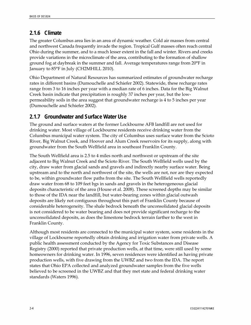
2.1.6 Climate The greater Columbus area lies in an area of dynamic weather. Cold air masses from central and northwest Canada frequently invade the region. Tropical Gulf masses often reach central Ohio during the summer, and to a much lesser extent in the fall and winter. Rivers and creeks provide variations in the microclimate of the area, contributing to the formation of shallow ground fog at daybreak in the summer and fall. Average temperatures range from 20°F in January to 85°F in July (CH2MHILL 2010).
Ohio Department of Natural Resources has summarized estimates of groundwater recharge rates in different basins (Dumouchelle and Schiefer 2002). Statewide, these recharge rates range from 3 to 16 inches per year with a median rate of 6 inches. Data for the Big Walnut Creek basin indicate that precipitation is roughly 37 inches per year, but the low-permeability soils in the area suggest that groundwater recharge is 4 to 5 inches per year (Dumouchelle and Schiefer 2002).
2.1.7 Groundwater and Surface Water Use The ground and surface waters at the former Lockbourne AFB landfill are not used for drinking water. Most village of Lockbourne residents receive drinking water from the Columbus municipal water system. The city of Columbus uses surface water from the Scioto River, Big Walnut Creek, and Hoover and Alum Creek reservoirs for its supply, along with groundwater from the South Wellfield area in southeast Franklin County.
The South Wellfield area is 2.5 to 4 miles north and northwest or upstream of the site adjacent to Big Walnut Creek and the Scioto River. The South Wellfield wells used by the city, draw water from glacial sands and gravels and indirectly nearby surface water. Being upstream and to the north and northwest of the site, the wells are not, nor are they expected to be, within groundwater flow paths from the site. The South Wellfield wells reportedly draw water from 68 to 109 feet bgs in sands and gravels in the heterogeneous glacial deposits characteristic of the area (House et al. 2008). These screened depths may be similar to those of the IDA near the landfill, but water-bearing zones within glacial outwash deposits are likely not contiguous throughout this part of Franklin County because of considerable heterogeneity. The shale bedrock beneath the unconsolidated glacial deposits is not considered to be water bearing and does not provide significant recharge to the unconsolidated deposits, as does the limestone bedrock terrain farther to the west in Franklin County.
Although most residents are connected to the municipal water system, some residents in the village of Lockbourne reportedly obtain drinking and irrigation water from private wells. A public health assessment conducted by the Agency for Toxic Substances and Disease Registry (2000) reported that private production wells, at that time, were still used by some homeowners for drinking water. In 1996, seven residences were identified as having private production wells, with five drawing from the UWBZ and two from the IDA. The report states that Ohio EPA collected and analyzed groundwater samples from the five wells believed to be screened in the UWBZ and that they met state and federal drinking water standards (Waters 1996).

2—PROJECT BACKGROUND
ES022411142701MKE 2-5
2.2 Previous Site Studies This section presents conclusions taken from previous investigations relevant to the RD. A full presentation of these studies can be found in the Remedial Investigation Report (CH2M HILL 2010) and in the Test Pit and Soil Sampling Results for the Former Lockbourne Air Force Base Landfill Site Investigation (CH2M HILL 2011a).
2.2.1 Supplemental Site Investigation (2011) Soils from the onsite borrow source area were deemed suitable for use as landfill cover soils based on geotechnical testing. Concentrations of COCs in soil may exceed industrial/commercial use levels; therefore some borrow source material may not be suitable cover material. Verification sampling will be conducted during the remedial action to demonstrate that COCs in onsite soils meet acceptable limits for use as landfill cover material.
Waste encountered in the east bank of the West Ditch consists primarily of construction and demolition debris with some lime and fly ash. The maximum depth of waste encountered there was 12 feet bgs.
Waste delineation activities provided additional information regarding the horizontal and vertical extent of waste in the waste excavation areas as shown in the design drawings. The horizontal and vertical extent of waste excavation areas were modified based on test pit information collected during the investigation.
The 2011 supplemental investigation memorandum is provided as Appendix J.
2.2.2 Additional Site Investigation (2008) The following observations and conclusions were made during additional site investigation (CH2M HILL 2009):
Waste encountered during trenching included municipal solid waste, construction and demolition debris, lime sludge, and black material that was similar in appearance to coal ash. Sheet 4 of the design drawings shows the test pits advanced during the 2008 investigation.
The data generated during the electromagnetic survey were consistent with results expected for trench-and-fill landfill techniques and correlated with previous electromagnetic surveys of the site.
Twenty temporary landfill gas monitoring points were installed at the site. Two rounds of methane sampling were conducted. Landfill gas measurements indicated that methane concentrations were below 1.25 percent. The threshold level for methane is 5 percent at or within the facility boundary and 1.25 percent in occupied structures per Ohio EPA. There are, however, no occupied structures onsite.

3. Summ
ary of Selected Remedy
and Performance Standards
ES022411142701MKE 3-1
SECTION 3
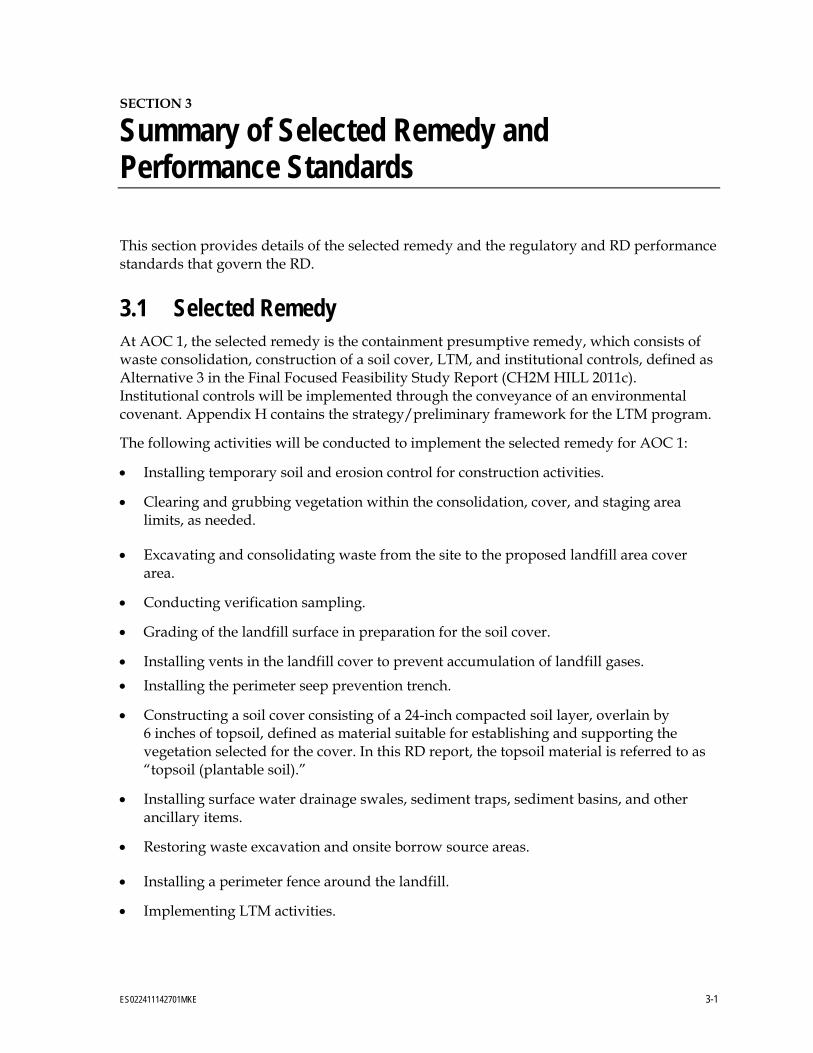
Summary of Selected Remedy and Performance Standards
This section provides details of the selected remedy and the regulatory and RD performance standards that govern the RD.
3.1 Selected Remedy At AOC 1, the selected remedy is the containment presumptive remedy, which consists of waste consolidation, construction of a soil cover, LTM, and institutional controls, defined as Alternative 3 in the Final Focused Feasibility Study Report (CH2M HILL 2011c). Institutional controls will be implemented through the conveyance of an environmental covenant. Appendix H contains the strategy/preliminary framework for the LTM program.
The following activities will be conducted to implement the selected remedy for AOC 1:
Installing temporary soil and erosion control for construction activities.
Clearing and grubbing vegetation within the consolidation, cover, and staging area limits, as needed.
Excavating and consolidating waste from the site to the proposed landfill area cover area.
Conducting verification sampling.
Grading of the landfill surface in preparation for the soil cover.
Installing vents in the landfill cover to prevent accumulation of landfill gases. Installing the perimeter seep prevention trench.
Constructing a soil cover consisting of a 24-inch compacted soil layer, overlain by 6 inches of topsoil, defined as material suitable for establishing and supporting the vegetation selected for the cover. In this RD report, the topsoil material is referred to as “topsoil (plantable soil).”
Installing surface water drainage swales, sediment traps, sediment basins, and other ancillary items.
Restoring waste excavation and onsite borrow source areas.
Installing a perimeter fence around the landfill.
Implementing LTM activities.

BASIS OF DESIGN
3-2 ES022411142701MKE
Implementing institutional controls through an environmental covenant that will restrict the future use of AOC 1 in a manner to prevent exposure to onsite groundwater, intrusive activities, and contact with waste.
At AOC 2, the selected remedy is an institutional control that will be implemented through the conveyance of an environmental covenant, defined as Alternative 2 in the Final Focused Feasibility Study Report (CH2M HILL 2011c), to restrict exposure to groundwater.
3.2 Remedial Design Performance Standards Although the Decision Document (CH2MHILL 2012) selected the site applicable or relevant and appropriate requirement (ARARs), the RD references various regulations as guidance. The Compliance Plan (Section 7) identifies which RD criteria are ARARs, waivers, and guidance.
3.2.1 Landfill Cover The landfill cover was designed to meet the Ohio EPA rules that were in place when the landfill ceased operation in 1979 (Ohio Administrative Code [OAC] 3745-27-10, effective July 29, 1976). The rules (1976 rules) were clarified by the Ohio EPA in two guidance documents: “Measureable Criteria for Questionable Pre-1990 Landfill Caps,” Ohio EPA Guidance no. 0123 (March 27, 1995) and “Measureable Criteria for Questionable Pre-1990 Landfill Caps,” Ohio EPA Guidance no. 0251 (March 24, 1995). The 1976 rules allow the minimum slope for the soil cover to be 1 percent. However, this design includes 5 percent slopes with a minimum allowable slope of 2.5 percent. The 24-inch soil cover will serve both as a barrier layer and vegetative layer described in the 1976 rules. In accordance with the above referenced guidance, the soil cover will have a maximum hydraulic conductivity of 1 × 10⁻⁶ centimeters per second as measured in the laboratory from samples collected in accordance with American Society for Testing and Materials (ASTM) D1556. (Field permeability of 1 × 10⁻⁵ centimeters per second as measured by either Boutwell or Single Double Ring Infiltrometer testing is also allowed.) The topsoil (plantable soil) will be seeded with a standard landfill grass mix on the cover area and with native grass species over other disturbed areas.
In addition to Ohio EPA guidance, the cover was designed to address potential risk to human health and the environment as presented in the Decision Document (CH2MHILL 2012).
3.2.2 Surface Water Management 3.2.2.1 During Construction Stormwater management during construction was designed using the State of Ohio Storm Water Program OAC 3745-39, which states that with land disturbance greater than 10 acres, temporary sediment controls are required. Design guidance in the State of Ohio’s Rainwater and Land Development Manual was used for sediment basin and sediment trap sizing.
Construction stormwater general permits require that a Stormwater Pollution Prevention Plan be developed to control pollutant sources. The remedial action contractor will be responsible for meeting the substantive requirements of the permit since this project is a
3—SUMMARY OF SELECTED REMEDY AND PERFORMANCE STANDARDS
ES022411142701MKE 3-3
Comprehensive Environmental Response, Compensation, and Liability Act action. The contractor will develop the stormwater pollution prevention plan. A combination of erosion control practices will be used at the site throughout construction, as described in Section 4.
3.2.2.2 Post-Construction Drainage swales will meet standard federal regulations for landfill surface water management (40 Code of Federal Regulations [CFR] 258.26 Run-on/runoff control systems), which requires control of the 24-hour duration 25-year return period storm.
Post-construction stormwater management was designed using the State of Ohio Storm Water Program, OAC 3745-39, which states that best management practices will include permanent vegetation and riprap-lined channels to control erosion. According to the general permit, if the project does not increase the amount of impervious area, no post-construction detention is required. The project does not include paving of pervious areas, and so no permanent detention was included.
3.2.3 Groundwater Monitoring The LTM strategy is included in Appendix H for demonstration purposes. The strategy will be updated after initial groundwater data have been collected as part of the remedial action. The initial groundwater sampling event will be described in a Sampling and Analysis Plan as part of the Remedial Action Work Plan. USACE will conduct the initial groundwater sampling event prior to remedial action construction to establish the groundwater monitoring program and to prepare the LTM Plan. The LTM Plan will be completed in accordance with Ohio EPA Guidance no. 0117, “Ground Water Monitoring Requirements for Closed Facilities” (May 9, 2005) following initial sampling and analysis.
3.2.4 Landfill Gas Monitoring Landfill gas monitoring is addressed in the LTM strategy. It was designed using field measurements of gas generation recorded during the 2008 site investigation (CH2M HILL 2009) and the site-specific gas generation calculations in Appendix B.1.
3.2.5 Institutional Controls Institutional controls are addressed in the LTM strategy. They will be implemented through environmental covenants that will restrict the future use of AOC 1 in a manner to prevent exposure to onsite groundwater, intrusive activities, and contact with waste. At AOC 2, institutional controls will be implemented through an environmental covenant to restrict exposure to groundwater. The landowner, the Columbus Regional Airport Authority, is agreeable to placing industrial/commercial use restrictions for AOC 1 and AOC 2.

4. Basis of Design

ES022411142701MKE 4-1
SECTION 4
Basis of Design
This section presents the components of the remedial action and documents the engineering analyses, calculations, and evaluations made to construct the landfill cover and maximize its long-term integrity.
4.1 Work Planning The contractor will prepare a Remedial Action Work Plan and other planning documents as needed to implement the RD, including a Health and Safety Plan (including an air monitoring plan), Sampling and Analysis Plan, Stormwater Pollution Prevention Plan, LTM Plan, and QA/QC Plan. A preliminary version of the QA/QC Plan is included as an appendix to this report. The contractor will revise the draft QA/QC Plan with project-specific information. The contractor will prepare a Sampling and Analysis Plan that will present the approach to conduct initial groundwater sampling and determine the following:
Onsite borrow source material is suitable (site human health COC concentrations below USEPA soil screening levels for industrial/commercial land use or USACE-approved background levels) for use as select fill, cover material, and or topsoil (plantable soil)
Offsite borrow source material is suitable (concentrations of semivolatile organic compounds, volatile organic compounds, pesticides, PCBs, and target analyte list metals below USEPA soil screening levels for residential land use or USACE-approved background levels) for use as select fill, cover material, and or topsoil (plantable soil)
Onsite soil outside the proposed cover area have site human health COC concentrations below USEPA soil screening levels for industrial/commercial land use or USACE-approved background levels
The plan also will outline data quality objectives, analytical methodologies, reporting limits, QA/QC activities pertaining to sampling analysis, laboratory requirements, and data assessment activities of the groundwater and verification sampling programs. The contractor will develop the LTM strategy after initial sampling is conducted.
4.2 Mobilization Contractor mobilization will consist of the following as needed:
Constructing temporary facilities, such as construction trailer, utilities, staging area, security fencing, and equipment decontamination facilities
Delivering equipment
Placing erosion and sediment control (ESC) features for staging areas if needed, such as silt fencing (site ESC measures are described below)

BASIS OF DESIGN
4-2 ES022411142701MKE
Equipment is expected to be transported by road. The temporary utilities will be active during construction of the cover.
4.3 Site Layout, Access, and Security 4.3.1 Site Layout and Access The soil cover extends over 23.3 acres. Sheet 5 of the design drawings (Appendix C) shows the limits of the proposed cover area. Waste consolidation will occur as shown on Sheets 7, 8, 9, and 10 of the design drawings.
The access roads that extend from the Columbus Regional Airport Authority property to the site will remain. Temporary access roads will be added during construction to address transport of excavated waste materials and borrow source material across the site. A permanent access road will be constructed near the southern boundary of the former radio transmitter station property with a double swinging gate for access to the landfill after closure (Sheet 15 of the design drawings). No additional access roads are proposed for access to monitoring wells and passive gas vents. Access to these features may be gained by driving or walking over the established vegetated final cover.
4.3.2 Site Security To prevent damage to the cover from vandalism or trespassing, temporary and permanent perimeter fencing and a gate will be installed as shown on Sheet 15 of the design drawings. During construction, the access gate located on Vause Road will be repaired and augmented so that it may be closed and secured during the remedial action. A temporary fence or concrete barriers will be installed on either side of the access gate so that vehicle traffic cannot bypass the gate. Temporary fencing may be required around waste excavation and borrow areas and will be addressed by the contractor in the Remedial Action Work Plan.
Permanent signage and fencing will be included along the perimeter of the waste consolidation boundary as shown on Sheet 15 of the design drawings.
4.4 Site Preparation Site preparation consists of collecting current topographic elevations; locating underground utilities; and clearing and grubbing in accordance with the technical specifications in Appendix D.
4.4.1 Survey An existing topographic survey of the ground surface prior to excavation and a topographic survey after excavation will be completed for preparation of record drawings.
4.4.2 Utility Locate The contractor is responsible for locating the utilities onsite before excavation, using the Ohio Utilities Protection Service (call 8-1-1 or 1-800-362-2764) and other resources.

4—BASIS OF DESIGN
ES022411142701MKE 4-3
4.4.3 Monitoring Well Abandonment Monitoring wells within the clearing and grubbing limits will be abandoned in accordance with the Technical Guidance Manual for Ground Water Investigations (Ohio EPA 1999 et seq.).
4.4.4 Clearing and Grubbing Clearing and grubbing consist of removing debris, trees, shrubs, and brush; removing or grinding of stumps and roots; and felling and removing of dead trees, partially dead trees and limbs, and trees and limbs that pose a hazard to workers. Debris will be disposed of under the landfill cover. Grubbed material will be mulched onsite and either placed on the surface to reduce erosion until vegetation is established or reduced to fine particles and mixed with topsoil (plantable soil). Excess mulch may be placed in the landfill. The area to be cleared and grubbed covers 69 acres.
Soil that meets the geotechnical and analytical requirements for topsoil (plantable soil) within AOC 1 can be stockpiled by the contractor for reuse in accordance with the technical specifications.
4.5 Construction Surface Water Management This section describes the ESC measures to be used during remedial action construction to manage surface water. ESC will be performed in three phases: clearing and grubbing and the construction of initial ESC measures; excavating the Waste Excavation Areas; and establishing final grade and permanent restoration. Appendix B.6 presents surface water calculations used to support the RD.
4.5.1 Erosion and Sediment Control Measures Runoff will be routed from disturbed areas to sediment basins or sediment traps through the use of temporary diversions and permanent swales. The sediment basins and traps will provide sediment control by collecting surface water runoff from uncontaminated areas and allowing that water to pool and sediments to settle out. See Section 4.8 for requirements for contact water management.
Once vegetation is established on the final grade, the basins will be modified to route water to rock-lined channels, as shown on Sheet 15 of the design drawings. Channels will be lined with rock for long-term erosion control.
4.5.1.1 Sediment Barriers Silt fences will be used to impede the flow and to provide for solids removal to reduce the transport of the sediment. These controls will be placed along the contours on long slopes and at the perimeters of the disturbance area, in places where temporary diversion berms cannot be used. Sheets 6 and 8 of the design drawings show the conceptual locations of silt fences. Silt fences will be maintained until site restoration is complete or until grading measures have removed the need for silt fence.

BASIS OF DESIGN
4-4 ES022411142701MKE
4.5.1.2 Geotextile Fabric The construction entrance will consist of stabilized stone underlain with a geotextile fabric at the construction site entrance. This will reduce the amount of soil removed from the construction site.
4.5.1.3 Temporary Diversion Berms Temporary diversion berms, consisting of a ditch and a berm, will intercept and route sediment-laden water to a sediment basin. Seeding and mulching should be utilized on slopes less than 3 percent and erosion matting for slopes greater than 3 percent.
4.5.1.4 Sediment Traps Two sediment traps will be used along the eastern edge of the cleared and grubbed area. The temporary diversion berms will convey runoff from disturbed areas to the sediment traps, where sediment will settle or filter out before the water is discharged offsite. A limit of 280 nephelometric turbidity units cannot be exceeded during construction on storm water effluents per pending (as of April 2012) USEPA guidelines and must be monitored during construction. A discussion on sampling methods and frequencies must be included in the Remedial Action Work Plan. Sedimentation basins are currently designed per State of Ohio requirements including 48-hour drawdown, 1,800 cubic feet per acre of drainage area, and 1,000 cubic feet of sediment storage per acre of drainage area.
4.5.1.5 Sediment Basins Four sediment basins will treat runoff from the disturbed area. Like sediment traps but larger, sediment basins treat water by removing sediment before water is discharged offsite. A limit of 280 nephelometric turbidity units cannot be exceeded during construction on storm water effluents per pending (as of April 2012) USEPA guidelines and must be monitored during construction. A discussion on sampling methods and frequencies must be included in the Remedial Action Work Plan. Sedimentation basins are currently designed per State of Ohio requirements including 48-hour drawdown, 1,800 cubic feet per acre of drainage area, and 1,000 cubic feet of sediment storage per acre of drainage area.
4.5.2 Erosion and Sediment Control Inspections During Construction During construction, ESC measures will be inspected weekly and within 24 hours of a storm of 0.25 inch of rain in a 24-hour period. An inspection report will document the names and titles of personnel making the inspection, date of inspection, the scope of the inspection, observations relating to the effectiveness of controls, and procedures to fix deficiencies, dates that repairs were completed, and repairs.
4.5.3 Erosion and Sediment Control Maintenance During Construction ESC measures will be maintained in working order to minimize the potential for erosion. Required maintenance identified in inspection reports will be completed as soon as practicable. Sediment barriers, such as silt fences, will be replaced as needed or as identified in weekly inspection reports. If results of an inspection (as outlined in the Surface Water Pollution Prevention Plan) completed during the remedial action indicate that erosion controls are insufficient, additional controls will be installed. Indications that controls are insufficient may include, but are not limited to, observations of sediment accumulation or water turbidity

4—BASIS OF DESIGN
ES022411142701MKE 4-5
downstream of control structures, recurrence of ground surface damage, appearance of eroded surfaces, or damage to controls. Maintenance procedures for insufficient controls identified during inspections are covered in the Surface Water Pollution Prevention Plan.
4.5.3.1 Water Application Multiple sources of water (East and West Ditches, sediment basins, fire hydrants in the surrounding area) can to provide water for dust control. The contractor will consider green and sustainable methods for dust control (GSR Report [Appendix G]).
4.5.3.2 Vegetation Application The contractor will complete weekly inspections to check placement/establishment of seed, fertilizer, or mulch from the topsoil (plantable soil). The soil to be seeded will be prepared and seeded as required by the technical specifications. Seeded surfaces will be inspected following storms that result in measurable quantities of rainfall (for example, 0.25 inch of rain in a 24-hour period). Maintenance will include application of lime and fertilizer when soil testing confirms the need. At least 1 year from the time of planting, and at least 85 to 90 percent growth density (as measured during visual inspection by USACE), is required for the seeding to be considered established.
4.5.3.3 Silt Fence Inspections will be done to ensure that the integrity of barriers is maintained and to quantify the sediment accumulation behind barriers after each storm. Sediment will be removed by shovel or mechanical excavators when accumulation approaches 50 percent of the height of the barrier. Damaged controls (through removal of sediments or from degradation by weather and storms) will be removed and replaced as necessary.
4.5.3.4 Drainage Channels Maintenance of drainage channels, both grass- and rock-lined, will consist of routine inspection to ensure that vegetation is not damaged, stones are not dislodged, and scouring of supporting materials has not occurred.
4.5.3.5 Sediment Basins and Traps Sediment basins and traps will be inspected weekly and after measurable rainfall (for example, 0.25 inch of rain in a 24-hour period). The sediment storage area will be cleaned out when sediment has filled the storage depth. Sediment traps will be reshaped to the original configuration. Sediment traps and basins are shown on Sheets 11 and 12 of the design drawings. Details for each basin are shown on Sheets 20 and 22 of the design drawings.
4.6 Current Landfill Conditions Waste materials, vegetation, and topography vary over the current landfill and the area proposed for waste consolidation.
Waste material in northern part of the landfill was placed in trenches up to 10 feet bgs, but most waste was observed in the top 4 feet. Municipal solid waste, lime sludge, black ash, and construction and demolition debris were observed during test pit installation. The

BASIS OF DESIGN
4-6 ES022411142701MKE
average thickness of the waste layer is about 4 feet. The terrain consists of ridges and valleys 5 to 10 feet in width. The difference in elevation between the ridges and the valleys averages roughly 3 feet. Lime sludge was seen on the surface of at least half of the area. Vegetation cannot grow on the surface where lime sludge is present. The access point in the northern area is a rough, grass covered path, underlain with construction and demolitions debris wide enough for a vehicle to enter.
In the southern part of the landfill, waste reportedly was placed in mounds and then at a later date covered with soil. Municipal solid waste, construction and demolition debris, and black ash were observed during test pit installation. Most of the area was inaccessible during previous investigations because of the dense vegetation. The depth of waste varies from ground surface to 8 feet bgs.
4.7 Volume of Waste Sheet 5 of the design drawings shows the limits of the proposed cover area. The cover will encompass 23.3 acres in AOC 1. Based on historic records, aerial photography, electromagnetic surveys, and previous test pit investigations, the northern area of AOC 1 contains the most in-place waste and the most municipal solid waste. Waste outside the proposed landfill perimeter will be excavated and consolidated within the cover limits.
The horizontal limit of waste was defined using the farthest extent of electromagnetic survey detections, which were verified through test pit excavations. Where electromagnetic survey detections did not show waste but test pits encountering waste had been advanced in the field, the horizontal limit of waste was determined based on topography and field observations. The depth of waste in the waste excavation areas were determined based on depth to waste information from test pit installation activities (CH2M HILL 2009; 2011a). In areas where the bottom of waste was not encountered, the depth of waste was estimated by adding 1 foot to the maximum test pit depth achieved. The volume of waste to be excavated and placed within the proposed cover area is 153,263 cubic yards. Waste Excavation Areas 1 through 6 are shown on Sheets 7, 8, and 9 of the design drawings and are further discussed below.
Soil removed during clearing and grubbing is not accounted for in the volume of waste quantity. The voids created in the cover area during clearing and grubbing are considered negligible and will be offset by swell in materials from Waste Excavation Areas. Appendix B.2 contains calculations estimating waste consolidation volumes.
4.7.1 Waste Excavation Area 1 Waste Excavation Area 1 contains lime sludge, black ash, and construction and demolition debris. On average, the waste extends to 3 to 5 feet bgs, but in places it is as deep as 8 feet. The waste material is mostly covered by soil and vegetation. The terrain is generally flat with mounds of waste material. Waste Excavation Area 1 is estimated to contain 54,720 cubic yards of waste.
4.7.2 Waste Excavation Area 2 Waste Excavation Area 2 contains municipal solid waste, black ash, and construction and demolition debris. On average, the waste extends to about 3 feet bgs, but in places it is as deep

4—BASIS OF DESIGN
ES022411142701MKE 4-7
as 6 feet. When the base runway was upgraded, concrete spoil was placed in the area. The municipal solid waste appears to be isolated to a small area in the eastern part of the excavation area. Waste Excavation Area 2 is estimated to contain 42,460 cubic yards of waste.
4.7.3 Waste Excavation Area 3 The waste material in Waste Excavation Area 3 includes construction and demolition debris. On average the waste extended to 4.5 feet bgs. The area contains pieces of concrete larger than 4 feet across by 6 inches thick and 4 feet long. Debris includes parking curbs and other construction and demolition debris. The demolition debris seems to consist mostly of concrete with little metal or wood. The area is partially covered in trees averaging about 1 foot in diameter. Waste Excavation Area 3 is estimated to contain 11,532 cubic yards of waste.
Buried construction and demolition debris extends into the former radio transmitter station property (Sheet 4 of the design drawings). That debris will not be consolidated under the landfill cover, because the area is not part of the Lockbourne AFB Landfill FUDS property and is not eligible for restoration by the FUDS program. The boundary of the former radio transmitter station property will be surveyed and staked before construction to prevent encroachment during excavation work.
Part of Waste Excavation Area 3 extends into AOC 2 (Sheet 4 of the design drawings). The waste extending into AOC 2 will be excavated and consolidated under the landfill cover.
Excavation in Waste Excavation Area 3 may extend into the wetland along the northern boundary of the proposed cover area (Sheet 8 of the design drawings). The wetland boundary will be surveyed and staked before construction begins. If waste excavation is necessary in the wetland, measures will be implemented to limit wetland impacts as much as practicable. Section 8 includes information on addressing wetland impacts.
4.7.4 Waste Excavation Area 4 Waste Excavation Area 4 contains construction and demolition debris and municipal solid waste. On average the waste extends to 4 feet bgs; the maximum depth observed was 7 feet. Several test pits were installed north of a berm along what appeared to be an old road. Waste Excavation Area 4 is estimated to contain 6,568 cubic yards of waste.
Waste Excavation Area 4 extends into a wetland. Based upon the estimated limits of the area (Sheet 8 of the design drawings), 0.34 acre of wetlands will be disturbed during the remedial action. The wetland boundary will be surveyed and staked before construction begins. Section 8 includes information addressing wetland impacts. Measures will be implemented to limit wetland impacts as much as practicable.
4.7.5 Waste Excavation Area 5 Waste Excavation Area 5 consists primarily of construction and demolition debris, lime sludge, and black fill. Lime sludge was observed on the surface, but most of the area is covered in grass or low brush. Waste Excavation Area 5 is estimated to contain 19,368 cubic yards of waste.
The American Electric Power (AEP) transmission line is located along the western edge of Waste Excavation Area 5 (Sheet 5 of the design drawings). There is a 50-foot easement in

BASIS OF DESIGN
4-8 ES022411142701MKE
either direction perpendicular to the centermost transmission line. Construction cannot occur within 40 feet of the power line tower. Appendix I specifies the AEP restrictions.
4.7.6 Waste Excavation Area 6 Construction and demolition debris encountered along the crest of the east bank of the West Ditch extends to depths of 10 to 12 feet bgs. Surficial waste appears to have rolled down the slope of the West Ditch. Waste Excavation Area 6 is estimated to contain 18,615 cubic yards of waste. Upstream of Waste Excavation Area 6, the West Ditch contains a reinforced concrete structure (Sheet 3 of the design drawings) formerly used by Lockbourne AFB as a flow control structure for surface water runoff. The structure acts as a dam pool and influences roughly 3,050 linear feet of the stream. In order to restore West Ditch to natural flow conditions (as agreed to by the Columbus Regional Airport Authority through previous surface water permitting actions with Ohio EPA), the concrete structure will be removed. Debris from the structure will be consolidated under the proposed cover or disposed of offsite. Surficial waste materials encountered in the bank near the structure will be placed under the cover.
Excess sediments that have accumulated behind the concrete structure will be removed, sampled, analyzed, and disposed of in accordance with state and federal regulations. The contractor will prepare a Demolition Plan detailing the demolition of the concrete structure, bank restoration, and sampling and disposal strategies for the sediments.
4.8 Contact Water Management The contractor must manage contact water during construction. The contractor will prepare a Contact Water Management Plan before beginning construction, as outlined in the technical specifications. The contact water management will include best management practices (BMPs) including minimization of the area of waste exposed at one time and the elimination of mingling contact and surface water runoff. Specific management practices will be included in the Remedial Action Work Plan. The contractor will provide for collection, sampling, and analysis of contact water. Treatment, transport, and disposal also may be necessary.
4.9 Waste Consolidation and Backfill 4.9.1 Waste Consolidation An estimated 160,374 cubic yards of waste has been identified for consolidation under the proposed cover from Waste Excavation Areas 1 through 6, as shown on Sheets 7, 8, and 9 of the design drawings. Large objects shall be buried at least 5 feet minimum from the proposed top of subgrade surface to allow for bridging and to minimize localized settlement.
The proposed top of waste grading shown on Sheet 10 of the design drawings allows for the consolidation of 155,500 cubic yards; therefore, the final slopes are expected to be greater than 5 percent. Sheet 18 of the design drawings lists control points for the top of waste, top of 24-inch cover, and the top of topsoil (plantable soil). The control points may be modified

4—BASIS OF DESIGN
ES022411142701MKE 4-9
during construction based on the actual waste placed within the cover area. The cover slopes currently are designed at 5 percent; the minimum slope will not be less than 2.5 percent or greater than 4H:1V. The contractor will be required to verify the slope stability of the final grading determined for the proposed cover.
If drums or hazardous wastes are encountered during the waste consolidation effort, hazards associated with the excavation of drums or hazardous waste will be determined before offsite disposal. Hazardous wastes or drums will be evaluated in accordance with the technical specifications (Appendix D).
4.9.2 Soil Sampling Onsite and offsite borrow source material will be sampled to demonstrate that the material will meet material requirements presented in the technical specifications (Appendix D).
Onsite borrow source material meeting the geotechnical requirements will be sampled for human health COCs, as appropriate, to meet the site reuse requirements. Human health COCs include polynuclear aromatic hydrocarbons (benz[a]anthracene, benzo[a]pyrene, benzo[b]fluoranthene, benzo[k]fluoranthene, dibenzo[a,h]anthracene, and indeno[1,2,3-cd]pyrene), PCB-1248, and lead. Concentrations of the human health COCs are required to be below USEPA soil screening levels for industrial/commercial land use or USACE-approved background levels for use as onsite borrow source material.
Offsite borrow source material meeting the geotechnical requirements will be sampled for semivolatile organic compounds, volatile organic compounds, pesticides, PCBs, and target analyte list metals. Concentrations of these analytes must be below the USEPA soil screening levels for residential land use or USACE-approved background levels.
4.9.3 Select Fill Select fill is soil used for backfill of waste excavation areas or general site grading. The onsite borrow source identified on Sheet 12 of the design drawings will provide 37,468 cubic yards of select fill to restore Waste Excavation Areas 3, 4, and 5 to the grades shown on Sheets 15 of the design drawings. Parts of Waste Excavation Areas 1 and 2, along with parts of the proposed borrow source area, will be regraded to promote surface water drainage and eliminate ponding. Further detail on select fill requirements is presented in the QA/QC Plan (Appendix F) and the technical specifications (Appendix D).
4.9.4 Landfill Cover Section Soil excavated from the onsite borrow area will be used for the landfill cover as described below. The reuse of onsite materials will depend on verification sampling (demonstration of COC concentrations below industrial/ commercial land use or background criteria) conducted as part of the remedial action. Appendix B.2 contains soil balance volume calculations. Excavation 5 feet deep in a source area of 16.5 acres will yield 133,100 cubic yards of soil, enough soil to meet the fill and cover material requirements listed below. If borrow material onsite is not suitable in sufficient quantities, material will be hauled in from offsite after verification sampling to demonstrate that chemical concentrations are below residential land use or background criteria. Borrow soils excavated from elevations beneath the UWBZ may require additional dewatering by the contractor.

BASIS OF DESIGN
4-10 ES022411142701MKE
4.9.4.1 Top of Waste The subgrade for the landfill cover will consist of excavated waste consolidated from areas outside of the cover limits. The material will be placed and compacted and act as fill material to achieve the top of waste grades before placement of the soil cover.
The top of waste will be graded in preparation for cover construction. The upper 1 foot of the waste surface will consist of waste material no greater than 6 inches in size. Select fill may be used to create a suitable surface for construction of the landfill cover. Large waste debris encountered during waste excavation or through demolition of the concrete structure must be broken and reduced in size before placement under the landfill cover. Large debris must be placed at least 2 feet below the final top of waste surface. Compaction will be measured by proof-rolling, as provided in the technical specifications (Appendix D).
4.9.4.2 Compacted Soil Cover The compacted soil cover is the 24-inch barrier and 6-inch vegetative layer (described below). The onsite borrow source area identified on Sheet 12 of the design drawings will provide the 69,244 cubic yards of soil needed for the 24-inch cover layer. Cover material requirements are discussed below and in the technical specifications.
The soil cover will consist of 24 inches of compacted soil cover. The cover layer will be of a low permeability material that stores moisture to help support vegetative growth and acts as a barrier layer to reduce vertical percolation of precipitation into the waste. The compacted soil cover will be placed and compacted as four 6-inch lifts. The soil cover must be compacted to achieve at least 95 percent compaction of a standard Proctor (ASTM D698) at optimum moisture content and achieve a field permeability of 1 × 10⁻⁵ centimeters per second or a laboratory permeability of 1 × 10⁻⁶ centimeters per second of Shelby tube samples. Further detail on soil cover requirements is presented in the QA/QC Plan (Appendix F) and the technical specifications (Appendix D).
4.9.4.3 Topsoil (Plantable Soil) Topsoil (plantable soil) is defined as material suitable for establishing and supporting the vegetation selected for the cover. In this RD, the topsoil material is referred to as “topsoil (plantable soil).” To complete the 6-inch topsoil layer, 21,164 cubic yards of soil will be needed. Topsoil (plantable soil) material requirements are discussed below and in the technical specifications (Appendix D).
Topsoil (plantable soil) will consist of 6 inches of soil with pH in the range of 6.0 to 7.5. If suitable soils are not present onsite in sufficient quantity, they will need to be imported from offsite. If the topsoil (plantable soil) onsite is not within the pH range of 6.0 to 7.5, the contractor can perform additional testing to determine if soils outside of the range can be used with the seeding requirements in the technical specifications (Appendix D).
The topsoil (plantable soil) layer will be placed with low ground-pressure equipment and compacted lightly, as required for access and stability and to support vegetation. The uppermost 2 inches of the layer will be scarified to provide a base for seeding and treated with limestone and fertilizer, as necessary. Further details of topsoil (plantable soil) requirements are presented in the QA/QC Plan (Appendix E) and technical specifications (Appendix D).

4—BASIS OF DESIGN
ES022411142701MKE 4-11
4.10 Cover System Design 4.10.1 Slope Stability Slope stability was calculated to show that the landfill cover grades will have a factor of safety against a sliding failure of at least 1.5 for the static condition. The standard of practice is to provide a factor of safety of 1.0 against dynamic failure. A critical cross section was used for both static and dynamic stability of drained and undrained materials.
4.10.1.1 Methods of Analysis Slope stability was analyzed using Rocscience’s program SLIDE, version 6.0. SLIDE analyzes the stability of slip surfaces using vertical slice limit equilibrium methods (such as Bishop, Janbu, Spencer). Individual slip surfaces were analyzed, and search methods were applied to locate the critical slip surface for the given slope. The site was analyzed for rotational (circular) and translational block failures using Bishop’s and Janbu’s methods. These methods are based on the principle of limiting equilibrium. That is, the method calculates shear strengths that would be required to just maintain equilibrium and then computes a factor of safety by dividing the available shear strength by the shear strength required to maintain stability. Critical surface search routing is used to determine the least stable failure surface. SLIDE iterates through a large number of potential failure surfaces and calculates the factor of safety of each surface. The lowest factor of safety is reported.
4.10.1.2 Selection of Engineering Parameters The critical engineering parameters for slope stability analysis of the site are the shear strengths of the soils comprising the east bank of the West Ditch. Triaxial testing was completed on remolded samples during the supplemental test pit investigation (CH2M HILL 2011a). Table 4-1 lists the engineering parameters used in the slope stability analysis. Both the current design slopes of 5 percent and the maximum allowable cover slope of 4H:1V were analyzed in the analysis. The contractor shall verify the slope stability of the final grading for the proposed cover during the remedial action. Appendix B.3 contains further details on references and source data.
4.10.1.3 Results The east bank of the West Ditch was selected as the critical cross section for slope stability analysis because of its steep 2H:1V slope and the presence of a short 4H:1V slope in the final grading. Waste located along the crest of the east bank of the West Ditch to depths of 10 to 12 feet (Waste Excavation Area 6) will be consolidated under the landfill cover. After excavation, a 30-foot-wide bench will exist at the crest of the slope. Appendix B.3 contains the slope stability analysis. The results of the analysis (Table 4-2) show a static condition factor of safety for both rotational and translational block methods exceeded the required 1.5 in addition to exceeding the required 1.0 factor of safety for dynamic conditions.
4.10.2 Settlement Settlement was calculated for the overall impact of the consolidated waste on the landfill subgrade. Overall elastic settlement and primary and secondary consolidation settlement were evaluated. Waste mass settlement was estimated based on typical expected settlement

BASIS OF DESIGN
4-12 ES022411142701MKE
values for the waste types encountered in the Waste Consolidation Areas. In this case, consolidation settlement will govern as the conservative case for analysis.
TABLE 4-1 Summary of Material Properties for Slope Stability Analysis Former Lockbourne AFB Landfill Basis of Design
Cover Material Base Material
Top Soila
Cover Soilb Wastea
Upper In Situ Clay Soilb
Upper Water Bearing Zonea
Lower In Situ Clay Soila
Density d (pounds per cubic foot) (dry)
75 100 80 100 100 100
Density, s (pounds per cubic foot) (saturated)
85 105 85 105 110 105
Thickness (ft) (or as shown) 0.5 2 Varies Varies Varies Varies
Drained Friction Angle (degrees) 30 24 26 24 30 24
Drained Cohesion (pounds per square foot)
25 225 150 225 0 225
Undrained Friction Angle (degrees) 30 0 26 0 30 0
Undrained Cohesion (pounds per square foot )
25 600 150 800 0 Varies based on depth
aEstimated based on references presented in the calculation in Appendix B.3 for two locations of the landfill cover; the highest and lowest consolidated waste fill heights. bLaboratory test results presented in the calculation in Appendix B.3.
TABLE 4-2 Summary of Results for Slope Stability Analysis Former Lockbourne AFB Landfill Basis of Design
Final Cover Stability, East Bank of West Ditch
Scenario
Rotational Rotational, Dynamic Minimum Factor of Safety
Required
Minimum Factor of Safety Required,
Dynamic Bishop Janbu Bishop Janbu
5% Rotational, Drained 1.99 1.77 1.72 1.56
1.5 1.0 5% Rotational, Undrained 2.41 2.39 2.14 2.10
4H:1V Rotational, Drained 1.91 1.81 1.68 1.59
4H:1V Rotational, Undrained 1.59 1.51 1.29 1.22
Block Block, Dynamic
5% Block, Drained 2.52 2.47 2.08 2.01
1.5 1.0 5% Block, Undrained 3.70 3.60 2.97 2.88
4H:1V Block, Drained 1.94 1.84 1.51 1.43
4H:1V Block. Undrained 1.89 1.80 1.51 1.43

4—BASIS OF DESIGN
ES022411142701MKE 4-13
4.10.2.1 Selection of Engineering Parameters The critical engineering parameters for settlement analysis are the unit weight of the waste materials, cover soils and in situ soils, consolidation parameters, including the preconsolidation pressure, compression index, and recompression index for the subsurface soils, and the depth to incompressible rock. The material properties listed in Table 4-3 were used to estimate total settlement.
TABLE 4-3 Universal Soil Loss Equation Values Former Lockbourne AFB Landfill Basis of Design
Activity C P K R
Closure with permanent vegetation, 95 to 100% cover 0.007 1 0.375 125
Source: Estimating Load Reduction for Agriculture and Urban BMPs Revised Soil Loss Equation Erosion Prediction Ohio. http://ohiodnr.com
4.10.2.2 Method of Analysis Overall settlement of the in situ soils under the load of the waste fill in the area of the proposed limit of waste consolidation was calculated using primary and secondary consolidation estimates. Clay soils were assumed to exist for the full depth, from the ground surface of the new elevation of the West Ditch crest to bedrock. Settlement was evaluated to determine whether differential settlements, due to the addition of waste as a surcharge load to the existing topography, would cause ponding on the final cover slopes. The settlement of the consolidated waste mass itself and the waste mass below grade was estimated using published settlement rates over time for landfills. It was assumed that the below grade waste would settle 6 percent of its total thickness under the load of the consolidated waste. It was then assumed that 10 percent of the consolidated waste mass depth itself would settle. Per the references listed in the calculation, settlement of pure municipal solid waste after closure is expected to be between 4 and 6 percent. Because the composition of the waste is unclear, the larger estimated thickness and settlement values were used.
4.10.2.3 Results The results of the analysis resulted in a maximum settlement under the highest waste filled area of 2.43 feet. The estimated maximum grade change on the final cover system due to foundation consolidation settlement is 0.05 percent, with a 0.50 percent grade change due to the settlement of the waste mass after waste consolidation and regrading. At a maximum, this will reduce the proposed 5 percent slope to 4.5 percent. The decrease in the final cover slope will not have a significant impact on final cover drainage. Appendix B.4 contains the settlement calculations.
4.10.3 Soil Cover Loss The final slope of the cover is designed to be 5 percent. Cover soil erosion can occur as a result of detachment and movement of soil particles due to raindrop impact and surface runoff.

BASIS OF DESIGN
4-14 ES022411142701MKE
4.10.3.1 Selection of Engineering Parameters and Method of Analysis The potential for soil erosion from the final slopes was analyzed using the Universal Soil Loss Equation. The equation predicts average annual soil loss as the product of six quantifiable factors.
A = (R) (C) (K) (LS) (P)
where A = computed soil loss in tons/acre/year R = rainfall energy factor (for Franklin County) C = cropping management factor K = soil erodibility factor (based on soil types) LS = slope/length/topographic factor (calculated from design berm spacing and
configuration) P = erosion control practice factor
4.10.3.2 Results Computations for the 5 percent slopes were made to assess the potential for erosion during construction and throughout post-closure, after vegetation has been established. The analyses presented in Appendix B.5 confirmed that the finished slopes will have an average annual soil loss of 0.97 ton per acre, less than 2 tons per acre per year recommended in Design and Construction of Covers for Solid Waste Landfills (U.S. Environmental Protection Agency [USEPA] 600/2-79-165, August 1979). Soil loss during construction was calculated for the area with the steepest and longest slopes on the west side of the landfill. That area is estimated to experience soil loss of 5 tons per acre per year during construction.
4.11 Passive Vents Gas generation estimates were calculated using the USEPA’s LandGEM Landfill Gas Emission Model, version 3.02. LandGEM is based on a first order decomposition rate equation for quantifying emissions of landfilled municipal solid waste. Based on visual assessment of waste during previous investigations, it was assumed that 10 to 20 percent of the waste present at the site is municipal solid waste (organic fraction). LandGEM was used to estimate the total emission from the municipal solid waste fraction of the waste, as other wastes encountered at the site do not generate gas. The model computed that 5 to 10 standard cubic feet per minute of gas is generated (as of 2011). The level of methane in units of standard cubic feet per minute was not detected above the reporting limit in 2011. Appendix B.1 contains details of the LandGEM modeling.
Even though levels of methane are calculated and field verified as negligible through measurements taken in 2008 (CH2M HILL 2009), passive gas vents will be constructed in the landfill cover to accommodate gas migration. Gas vent locations are shown on Sheet 16 of the design drawings. The vents are spaced at roughly one per acre across the surface of the landfill. Each vent will consist of 4-inch polyvinyl chloride (PVC) schedule 80 riser pipes that will penetrate the final cover system and vent gas directly to the atmosphere. Below the cover soils, the vent will extend into a 12- by 12- by 6-inch gravel collection trench with an 8-ounce-per-square-yard geotextile placed on top of the gravel prior to cover soil placement. The riser

4—BASIS OF DESIGN
ES022411142701MKE 4-15
pipe will be connected into a tee with two 5-foot schedule 80 slotted collection pipes (all PVC) running in the center of the gravel collection layer. Details of a typical gas vent are presented on Sheet 20 of the design drawings.
Passive gas vents and trenches will be constructed before and concurrently with placement of the 24-inch cover soil so as not to damage the cover system.
4.12 Seep Prevention Trench A seep prevention trench located along the cover perimeter within the waste mass will prevent migration of seeps through the landfill cover to outside the landfill. The trench will be filled with the clean, crushed American Association of State Highway and Transportation Officials (AASHSTO) #57 stone and sloped at 1 percent toward manholes around the perimeter of the landfill. The trench will be wrapped with an 8-ounce-per-square-yard geotextile to prevent migration of fines from the surrounding soils and waste material into the trench. The 48-inch high-density polyethylene (HDPE) access manholes will allow a vacuum truck or similar equipment to pump out water if seeps are observed around the toe of the cover or as needed during LTM. A continuous perforated pipe will be installed around the landfill in the seep prevention trench and drainage, and a 4-inch sampling port for water level measurements and inspections will be provided in each manhole lid. Sheets 15 and 20 of the design drawings show the details of the seep prevention trench.
Based on the average daily flow rates estimated by the Hydrologic Evaluation of Landfill Performance model (Appendix B.7), it is anticipated that the waste mass may become saturated in the long term. Since water may accumulate in the manholes, the LTM Plan will include water level measurements of the manholes during cover inspection events, but at least annually.
4.13 Post-Construction Surface Water Management Peak flow rates for runoff of surface water from the site were calculated using the Soil Conservation Service curve number method. Runoff rates for drainage swales were calculated using methodology found in 40 CFR 258 landfill requirements for the 24-hour duration 25-year return period storm. Runoff rates and sizing for temporary sediment basins outlet control were calculated using guidance taken from the State of Ohio Storm Water Program OAC 3745-39. Appendix B.6 contains the calculations for surface water runoff.
The contractor must manage contact water—water that has been in contact, however briefly, with waste present in excavations or as part of the consolidated waste mass—during construction, as discussed above.
4.13.1 Erosion and Sediment Control Measures 4.13.1.1 Temporary Cover As sections of the cover are completed to final grade, temporary mulching or erosion blankets will be used to stabilize the soil surface until vegetation can be established. The cover will shield the surface from erosion by rainfall. Erosion blankets will be used to

BASIS OF DESIGN
4-16 ES022411142701MKE
stabilize areas with slopes steeper than 3H to 1V until vegetation can be established. Stabilization reduces the formation of rills and gullies on slopes, thus minimizing soil loss.
4.13.1.2 Permanent Vegetative Cover Permanent vegetative cover will be used on soil surfaces, which are at final grade. Soils will be seeded with a native seed mixture, depending on the temperature at time of planting. Details regarding vegetative cover are provided in Section 4.15 and in the technical specifications (Appendix D).
4.13.2 Surface Water Management Surface water runoff from the northwest side of landfill (along the power line easement) will be conveyed within a grassed swale along the landfill perimeter and through overland sheet flow, as shown on Sheet 14 of the design drawings. Runoff will then flow through the grassed-lined swale, across part of the AEP easement, and finally through the rock-lined channel for release to the West Ditch. Grading in this part of the easement will be 1 to 2 feet below grade to convey water from the northeastern part of the landfill to the West Ditch (CH2M HILL 2011d).
Runoff from the northeast side of the landfill will be conveyed through a grassed swale along the landfill perimeter and discharged to an overland flow path that conveys surface water to wetlands on the northeastern part of the site. A sediment basin will be temporarily used to settle sediment from construction activities. Sheet 11 of the design drawings shows the details of drainage flows to and from the sediment basin. The sediment basin will be removed after construction and stabilization of the landfill cover. Runoff will be conveyed through grassed swales to existing topography that conveys water to the wetlands.
Surface water from Waste Excavation Area 5 along the west side of the landfill will be routed through temporary diversion berms during construction and drain to sediment basins. The basins will drain to one of two rock-lined trapezoidal channels that discharge into the West Ditch. Runoff will be over the landfill cap to the 30-foot-wide grassed ledge created along the West Ditch after excavation of the waste material. Water will then flow north or south along the ledge to a rock-lined trapezoidal channel that discharges to the West Ditch.
Surface water from the east and southeast side of the landfill will be conveyed in a grassed swale along the perimeter of the north and east parts of the landfill before discharge into the West Ditch. During construction, runoff from the waste excavation areas south of the landfill will drain to a swale and be conveyed in a rock-lined trapezoidal channel before discharge to the West Ditch.
Runoff from the east side of the borrow source area and waste excavation areas will be directed to drainage channels before being discharged off the east perimeter of the site. Waste excavation areas will be reshaped to continue to promote drainage to the east, whereas the borrow source areas will be regraded to promote drainage to the west. Areas draining to the east will drain overland off the site. Areas draining to the west will drain to grassed swales and rock-lined channels before discharging to the West Ditch.

4—BASIS OF DESIGN
ES022411142701MKE 4-17
Surface water from the south borrow source area will be directed to the West Ditch in a rock-lined trapezoidal channel. Depending upon final grading, the same rock channel will be used following construction to drain runoff to the West Ditch.
Excavation along the east bank of the West Ditch will occur down to elevation 720 feet to accommodate landfill cover construction. The 720-foot excavation elevation is about 20 feet above the normal surface water flow elevation in the West Ditch. The elevation of the crest of west bank in this section of the West Ditch is at approximately 713 feet in elevation. During flood events, water may rise in the West Ditch and overflow the west bank of the West Ditch. Since the east bank is approximately 7 feet higher than the west bank, the landfill cover will be unaffected by flooding that might occur along the West Ditch.
4.13.3 Post-Construction Erosion and Sediment Control Inspections Inspections of ESC measures described in Section 4.13.2 are discussed in the LTM strategy provided in Appendix H.
4.13.4 Post-Construction Erosion and Sediment Control Maintenance ESC measures will be maintained in working order to minimize the potential for erosion. Required maintenance identified in inspection reports will be completed as soon as practicable. If inspection reveals that controls are insufficient, additional controls will be installed. ESC measures will be maintained and inspected by the contractor for a minimum of one year beyond completion of punch list items or until suitable vegetation is established as determined by the USACE.
4.14 Post-Construction Survey A topographic survey will be conducted following cover implementation to verify drainage requirements and payment quantities. The post-construction survey shall include items necessary to document the as-built condition of the remedial action; this may include but is not limited to drainage features, landfill waste limits, cover limits, cover grades, borrow areas, monitoring wells, and gas vents.
4.15 Site Restoration Following completion of cover placement, the topsoil (plantable soil) will be seeded with a standard landfill grass mix on the landfill cover and with native grass species over other areas disturbed during construction. Vegetation will be stabilized using the lime, fertilizer, and seeding mixes and application rates in the technical specifications. If the cover system is placed at a time when application of the permanent seed mixtures is not possible, alternative stabilization measures, such as temporary seed mixes or mulching, will be employed in accordance with the technical specifications (Appendix D).
4.16 Reporting A construction completion report will be prepared to document construction activities and present design variances.

BASIS OF DESIGN
4-18 ES022411142701MKE
4.17 Demobilization As part of demobilization, the contractor will remove equipment, excess material, construction facilities, and ESCs. Street cleaning may need to be completed before and during demobilization.
4.18 Institutional Controls USACE will implement institutional controls as environmental covenants in coordination with Columbus Regional Airport Authority.
4.19 Long-Term Management LTM consists of groundwater monitoring, landfill gas monitoring, inspections, and maintenance. LTM will begin once construction is complete, as defined by completion of the landfill cover, establishment of vegetation, and initial groundwater sampling with COC analysis. LTM activities will assess potential offsite migration of the COCs in groundwater; monitor that landfill gas does not pose an explosion hazard; and ensure that the landfill cover prevents contact with the waste and reduces surface water infiltration. The groundwater monitoring program will evaluate the continued attenuation of COCs in groundwater and assess the need for additional corrective action to ensure protection of public health and welfare. The general procedures and LTM Strategy for inspection and monitoring, described in Appendix H, are included for demonstration purposes. The guidelines should be developed and presented in the LTM Plan to reflect actual inspection procedures and sampling. The LTM Plan will be finalized following cover implementation and initial groundwater sampling and analysis.

5. Construction Documents

ES022411142701MKE 5-1
SECTION 5
Construction Documents
5.1 Design Drawings The design drawings (Appendix C) include the following sheets:
Sheet No. Title
1 Title Sheet, Vicinity and Location Maps, and Index to Drawings
2 Abbreviations, Designations, and Civil Legend
3 Existing Site Plan
4 Limits of Waste from Previous Investigations
5 Construction Overview
6 Phase One Erosion and Sediment Control Plan
7 Waste Excavation Grading Plans and Sections (1 of 3)
8 Waste Excavation Grading Plans and Sections (2 of 3)
9 Waste Excavation Grading Plans and Sections (3 of 3)
10 Top of Waste Grading Plan
11 Phase Two Erosion and Sediment Control Plan
12 Borrow Excavation Grading Plan and Sections
13 Top of 24” Cover Soil Grading Plan
14 Phase Three Erosion and Sediment Control Plan
15 Final Grading Plan and Site Restoration
16 Passive Gas Vent Layout Plan
17 Site Sections
18 Construction Staking Tables (1 of 2)
19 Construction Staking Tables (2 of 2)
20 Details
21 Details
22 Standard Details
5.2 Technical Specifications The technical specifications (Appendix D) include the following:

BASIS OF DESIGN
5-2 ES022411142701MKE
DIVISION 01—GENERAL REQUIREMENTS
01 11 00 Summary of Work* 01 14 00 Work Restrictions* 01 20 00.00 20 Price and Payment Procedures* 01 22 00.00 10 Measurement and Payment* 01 26 00 Contract Modification Procedures* 01 31 13 Project Coordination 01 31 19 Project Meetings 01 32 01.00 10 Project Schedule 01 33 00 Submittal Procedures* 01 35 29.13 Safety and Emergency Response Procedures for Contaminated Sites* 01 50 00 Temporary Construction Facilities and Controls 01 51 00 Field Engineering/Surveying 01 57 20.00 10 Environmental Protection 01 57 21.00 Contact Water Management 01 57 23 Temporary Stormwater Pollution Control 01 61 00 Common Product Requirements
* Requirements related to this specification will be detailed in the contractor's base contract and task order for the project. DIVISION 02—EXISTING CONDITIONS
02 32 00 Subsurface Drilling, Sampling, and Testing 02 56 14 Cover Soil Layer 02 61 00 Consolidation of Waste Material 02 66 00 Select Fill and Topsoil (Plantable Soil) for Landfill Cover 02 81 00 Transportation and Disposal of Hazardous Materials
DIVISION 31—EARTHWORK
31 00 00 Earthwork 31 11 00 Clearing and Grubbing
DIVISION 32—EXTERIOR IMPROVEMENTS
32 31 13 Chain Link Fences and Gates 32 92 19 Seeding
DIVISION 33—UTILITIES
33 05 11 High Density Poly-Ethylene and Polyvinyl Chloride Pipe 33 24 13 Groundwater Monitoring Wells

6. Green & Sustainable Design Elements

ES022411142701MKE 6-1
SECTION 6
Green and Sustainable Design Elements
This section discusses the overall GSR approach to the project. GSR was considered and incorporated as appropriate throughout the RD process. Appendix G presents the GSR Report for the site. GSR can be defined as follows:
The practice of considering all environmental effects of remedy implementation and incorporating options to maximize net environmental benefit of cleanup actions. (DoD memorandum, “Consideration of Green and Sustainable Remediation Practices in the Defense Environmental Restoration Program,” August 10, 2009)
Further, GSR practices are those that do the following:
Minimize total energy use and maximize use of renewable energy. Minimize air pollutants and greenhouse gas emissions. Minimize water use and impacts to water resources. Reduce, reuse, and recycle material and waste. Protect land and ecosystems.
These GSR practices can be considered at two levels or phases in a project such as this. The first phase is at the strategic level, when the overall RD approach is developed. This was done in developing the Final Focused Feasibility Study Report (CH2M HILL 2011c) and the Decision Document (CH2MHILL 2012). These generally are big picture considerations involving the general remedial approach and net impacts on the environment. The second phase is at the RD level. These practices typically are more detailed as to the specifics of how the remedial action is implemented, constructed, operated, and monitored.
The development of GSR elements for the project was guided by several BMPs developed by USACE for the project (Appendix G). In addition, USACE has a draft guidance document on incorporating GSR and a list of 64 BMPs. The USEPA’s BMPs cover mostly RD-level GSR elements, whereas USACE’s cover both strategic level and RD-level GSR elements (USEPA 2009).
The BMPs were reviewed, then narrowed down to those that are applicable and those that are cost-effective and implementable for the site. The practical BMPs have been incorporated into the RD, as discussed in the following section.
6.1 Strategic Level GSR Elements Although not specifically defined as GSR elements in the focused feasibility study and the Decision Document, the following GSR elements were incorporated into the RD:
Select a soil cover comparable to a Resource Conservation and Recovery Act (RCRA) type of cap. The proposed final cover will meet an equivalent performance standard as a RCRA cap, but using onsite materials for the soil cover.
BASIS OF DESIGN
6-2 ES022411142701MKE
Balance future land use considerations by allowing for multiple reuse options.
Balance the dimensions of the cover versus the area to be excavated, thus maximizing reuse of the site for industrial/commercial purposes.
Complete site restoration activities quickly, such as seeding and other erosion control items.
6.2 Remedial Design Level GSR Elements The following RD-level GSR elements have been incorporated into the RD package:
Propose a cut and fill borrow source onsite for cover soil, select fill, and topsoil (plantable soil) materials.
Use native species for revegetation.
Quickly and efficiently implement seeding and erosion restoration items at the end of the construction so as to limit erosion impacts.
Remove the West Ditch reinforced concrete structure, reducing the need for two construction efforts at the same site and thus minimizing the use of equipment and resources.
Consolidate the reinforced concrete structure debris under the landfill cover, minimizing waste generation requiring offsite disposal.
Minimize dust during construction activities by spraying water or by laying biodegradable mats, tarps, or materials.
Select and place rock-lined channel protection at the outlets of swales and pipes.
The following GSR language is included in the technical specifications.
Employ sustainable practices to the maximum extent practicable during performance of the work. Sustainability practices to be used in performing the work may include the following:
Minimize vehicle miles driven including mobilization mileage, crew travel mileage, equipment and materials delivery mileage (bulk shipments), and maintenance/ repair mileage.
Limit vehicle idling. Use alternative fuels for equipment and vehicles. Use vehicles meeting new USEPA clean diesel standards, or upgrade to new
emissions controls (such as diesel oxidation catalysts, diesel particulate filters, and closed crankcase ventilation filtration systems) to reduce particulate matter, carbon monoxide, and nitrogen oxides in exhaust.
Minimize packaging waste. Recycle packaging waste.

6—GREEN AND SUSTAINABLE DESIGN ELEMENTS
ES022411142701MKE 6-3
Use recycled or recycled-content material (such as paper towels, trash bags or plastic sheeting, or materials packaging) as applicable.
Reuse materials where applicable. Use local resources and materials, including local sources of water for dust suppression. Use reasonable measures to minimize and suppress fugitive emissions of dust,
vapors, and other site materials during site work. Complete an evaluation of Occupational Safety & Health Administration’s Hazardous
Waste Operations and Emergency Response Standard (29 CFR 1910.120/29 CFR 1926.65) applicability, to support efficient resource use.
6.3 Green and Sustainable Remediation Report The following items were included as recommendations in the final GSR report:
1. Evaluate the pros and cons of complete versus partial removal of the West Ditch concrete structure.
Response—Partial removal was considered in the 60 percent remedial design submittal. However, complete removal is now planned because of potential stability problems with leaving part of the structure behind.
2. Determine if there are technical issues that would preclude leaving stumps in place in the area that will be covered.
Response—Potential for development of preferential pathways and for additional differential settlement is increased if stumps are left within the footprint of the landfill. Therefore, areas of disturbance will be grubbed in accordance with the technical specifications (Appendix D).
3. Evaluate the idea to dig out an area to allow pooling of surface water for use during construction.
Response—Temporary ponds (sediment basins) are incorporated into the RD for sediment control, but the ponded water is not proposed for reuse in the RD. The contractor can consider the East or West Ditch as a water source for dust control.
4. Perform a detailed technical and feasibility evaluation to maximize potential use of mulch generated by vegetation clearing for other aspects of the remedial action construction.
Response—The reuse of onsite soils and mulch as the basis for creation of topsoil (plantable soil) for the cover will be evaluated by the contractor and used if deemed suitable. Importation of topsoil (plantable soil) is proposed if onsite soils are not deemed suitable.
5. Evaluate use of Hydrosleeves for groundwater sampling to eliminate/reduce purge water.

BASIS OF DESIGN
6-4 ES022411142701MKE
Response—The method of groundwater sampling will be established after groundwater data have been collected as part of LTM. Hydrosleeves will be evaluated as a potential sampling method during development of the final LTM Plan.
6. Evaluate potential alternatives for dust control.
Response—The contractor will choose means and methods for dust control. Language has been added to the technical specifications encouraging the use of green and sustainable methods for dust control during the remedial action.

7. Compliance Plan

ES022411142701MKE 7-1
SECTION 7
Compliance Plan
Table 7-1 summarizes the ARARs for the site. Waivers are being applied to ARARs 1, 2, and 4 (as listed in Table 7-1). As noted, the landfill cover was designed to meet the Ohio EPA rules in place when the landfill ceased operation in 1979. The 1976 rules were clarified by the Ohio EPA in two guidance documents: “Measureable Criteria for Questionable Pre-1990 Landfill Caps” (Guidance no. 0123, March 27, 1995); and “Measureable Criteria for Questionable Pre-1990 Landfill Caps” (Guidance no. 0251, March 24, 1995). Table 7-2 indicates where in the BOD document each ARAR is addressed and incorporated into the RD. Table 7-3 indicates other regulations that were referenced and used for further guidance in the RD, but the regulations or guidance documents listed are not ARARs.

BASIS OF DESIGN
7-2 ES022411142701MKE
TABLE 7-1 Summary of ARARs Former Lockbourne AFB Landfill Basis of Design
ARARs Description of Regulation Comments
1 OAC 3745-27-08 Construction Specifications for Sanitary Landfills
Specifies the minimum requirements for soil and clay layers, granular drainage layer, geosynthetics, leachate management system, gas monitoring system, etc. Describes minimum standards for construction requirements for sanitary landfill facilities.
In coordination with Ohio EPA, USACE will be applying a waiver to this ARAR.
2 OAC 3745-27-10 Groundwater monitoring program for a sanitary landfill facility
Requires groundwater monitoring program for all sanitary landfill facilities. Requires that the system consist of a sufficient number of wells that are located so that samples indicate both upgradient (background) and downgradient water samples. Details minimum requirements that the system must be designed to meet. Details sampling and analysis procedures. Specifies procedures for assessment and correction of contamination.
In coordination with Ohio EPA, USACE will be applying a waiver to this ARAR.
3 OAC 3745-27-13 (H) Sections 7 and 8 Disturbances Where Hazardous or Solid Waste Facility was Operated
Describes substantive limitations on any proposed filling, grading, excavating, building, drilling, or mining on land where a hazardous waste facility or solid waste facility was operated and how the activities will be accomplished.
4 OAC 3745-27-11 (G) and (H) Final Closure of Sanitary Landfill Facilities
Requires closure of a landfill in a manner which minimizes the need for post-closure maintenance and minimizes post-closure formation and release of leachate and explosive gases to air, soil, groundwater, or surface water. Specifies acceptable cap design; barrier layer, granular drainage layer, soil and vegetative layer. Provides for use of comparable materials to those specified with approval of Director.
In coordination with Ohio EPA, USACE will be applying a waiver to this ARAR.
5 OAC 3745-17-08 (B) Restriction of emission of fugitive dust
Requires reasonably available control measures to prevent fugitive dust from becoming airborne.
6 40 CFR 230.10 Guidelines for Specification of Disposal Sites for Dredged or Fill Material
Requires appropriate and practicable steps are taken that minimize potential adverse impacts of the discharge of dredged or fill material on the aquatic ecosystem.

SECTION 7 COMPLIANCE PLAN
ES022411142701MKE 7-3
TABLE 7-2 ARAR Compliance Evaluation Matrix Former Lockbourne AFB Landfill Basis of Design
ARARs Description of Regulation Location and Description of
Compliance Discussion
1 OAC 3745-27-08 Construction Specifications for Sanitary Landfills
Specifies the minimum requirements for the soil and clay layers, granular drainage layer, geosynthetics, leachate management system, gas monitoring system, etc. Describes minimum standards for construction requirements for sanitary landfill facilities.
Specific requirements of this ARAR are waived. Equivalent standards of performance related to this ARAR are shown in the BOD throughout Sections 3 and 4, technical specifications and QA/QC Plan.
2 OAC 3745-27-10 Groundwater monitoring program for a sanitary landfill facility
Requires groundwater monitoring program for all sanitary landfill facilities. Requires that the system consist of a sufficient number of wells that are located so that samples indicate both upgradient (background) and downgradient water samples. Details minimum requirements that the system must be designed to meet. Details sampling and analysis procedures. Specifies procedures for assessment and correction of contamination.
Specific requirements of this ARAR are waived. Equivalent standards of performance related to this ARAR are shown in the BOD Section 3.2.3, design drawings and LTM Strategy.
3 OAC 3745-27-13 (H) Sections 7 and 8 Disturbances Where Hazardous or Solid Waste Facility was Operated
Describes substantive limitations on any proposed filling, grading, excavating, building, drilling, or mining on land where a hazardous waste facility or solid waste facility was operated and how the activities will be accomplished.
RD considerations related to this ARAR are shown in the BOD Section 4.9 and 4.10, technical specifications and OA/QC Plan.
4 OAC 3745-27-11 (G) and (H) Final Closure of Sanitary Landfill Facilities
Requires closure of a landfill in a manner which minimizes the need for post-closure maintenance and minimizes post-closure formation and release of leachate and explosive gases to air, soil, groundwater, or surface water. Specifies acceptable cap design; barrier layer, granular drainage layer, soil and vegetative layer. Provides for use of comparable materials to those specified with approval of Director.
Specific requirements of this ARAR are waived. Equivalent standards of performance related to this ARAR are shown in the BOD Section 3.2, technical specifications and QA/QC Plan.
5 OAC 3745-17-08 (B) Restriction of emission of fugitive dust
Does not allow anyone to cause or permit any fugitive dust source to be operated; or any materials to be handled, transported, or stored; or a building or its appurtenances or a road to be used, constructed, altered, repaired, or demolished without taking or installing reasonably available control measures to prevent fugitive dust from becoming airborne.
RD considerations related to this ARAR are shown in the technical specifications and QA/QC Plan.
6 40 CFR 230.10 Guidelines for Specification of Disposal Sites for Dredged or Fill Material
Requires appropriate and practicable steps are taken that minimize potential adverse impacts of the discharge of dredged or fill material on the aquatic ecosystem.
RD considerations related to this ARAR are included in the BOD, Section 8.2.3.4.
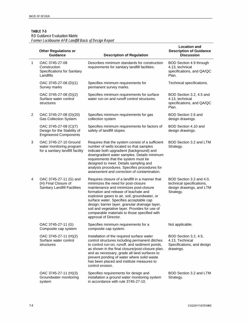
BASIS OF DESIGN
7-4 ES022411142701MKE
TABLE 7-3 RD Guidance Evaluation Matrix Former Lockbourne AFB Landfill Basis of Design Report
Other Regulations or Guidance Description of Regulation
Location and Description of Guidance
Discussion
1 OAC 3745-27-08 Construction Specifications for Sanitary Landfills
Describes minimum standards for construction requirements for sanitary landfill facilities.
BOD Section 4.9 through 4.13, technical specifications, and QA/QC Plan.
OAC 3745-27-08 (D)(1) Survey marks
Specifies minimum requirements for permanent survey marks.
Technical specifications.
OAC 3745-27-08 (D)(2) Surface water control structures
Specifies minimum requirements for surface water run-on and runoff control structures.
BOD Section 3.2, 4.5 and 4.13, technical specifications, and QA/QC Plan.
2 OAC 3745-27-08 (D)(20) Gas Collection System
Specifies minimum requirements for gas collection system
BOD Section 2.6 and design drawings.
OAC 3745-27-08 (C)(7) Design for the Stability of Engineered Components
Specifies minimum requirements for factors of safety of landfill slopes.
BOD Section 4.10 and design drawings.
3 OAC 3745-27-10 Ground water monitoring program for a sanitary landfill facility
Requires that the system consist of a sufficient number of wells located so that samples indicate both upgradient (background) and downgradient water samples. Details minimum requirements that the system must be designed to meet. Details sampling and analysis procedures. Specifies procedures for assessment and correction of contamination.
BOD Section 3.2 and LTM Strategy.
4 OAC 3745-27-11 (G) and (H) Final Closure of Sanitary Landfill Facilities
Requires closure of a landfill in a manner that minimizes the need for post-closure maintenance and minimizes post-closure formation and release of leachate and explosive gases to air, soil, groundwater, or surface water. Specifies acceptable cap design; barrier layer, granular drainage layer, soil and vegetative layer. Provides for use of comparable materials to those specified with approval of Director.
BOD Section 3.2 and 4.0, technical specifications, design drawings, and LTM Strategy.
OAC 3745-27-11 (G) Composite cap system
Specifies minimum requirements for a composite cap system.
Not applicable.
OAC 3745-27-11 (H)(2) Surface water control structures
Installation of the required surface water control structures including permanent ditches to control run-on, runoff, and sediment ponds, as shown in the final closure/post-closure plan, and as necessary, grade all land surfaces to prevent ponding of water where solid waste has been placed and institute measures to control erosion.
BOD Section 3.2, 4.5, 4.13, Technical Specifications, and design drawings.
OAC 3745-27-11 (H)(3) Groundwater monitoring system
Specifies requirements for design and installation a ground water monitoring system in accordance with rule 3745-27-10.
BOD Section 3.2 and LTM Strategy.
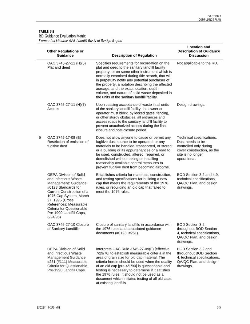
SECTION 7 COMPLIANCE PLAN
ES022411142701MKE 7-5
TABLE 7-3 RD Guidance Evaluation Matrix Former Lockbourne AFB Landfill Basis of Design Report
Other Regulations or Guidance Description of Regulation
Location and Description of Guidance
Discussion
OAC 3745-27-11 (H)(5) Plat and deed
Specifies requirements for recordation on the plat and deed to the sanitary landfill facility property, or on some other instrument which is normally examined during title search, that will in perpetuity notify any potential purchaser of the property, a notation describing the affected acreage, and the exact location, depth, volume, and nature of solid waste deposited in the units of the sanitary landfill facility.
Not applicable to the RD.
OAC 3745-27-11 (H)(7) Access
Upon ceasing acceptance of waste in all units of the sanitary landfill facility, the owner or operator must block, by locked gates, fencing, or other sturdy obstacles, all entrances and access roads to the sanitary landfill facility to prevent unauthorized access during the final closure and post-closure period.
Design drawings.
5 OAC 3745-17-08 (B) Restriction of emission of fugitive dust
Does not allow anyone to cause or permit any fugitive dust source to be operated; or any materials to be handled, transported, or stored; or a building or its appurtenances or a road to be used, constructed, altered, repaired, or demolished without taking or installing reasonably available control measures to prevent fugitive dust from becoming airborne.
Technical specifications. Dust needs to be controlled only during cover construction, as the site is no longer operational.
OEPA Division of Solid and Infectious Waste Management: Guidance #0123 Standards for Current Construction of a 1976 Cap System, March 27, 1995 (Cross References: Measurable Criteria for Questionable Pre-1990 Landfill Caps, 3/24/95)
Establishes criteria for materials, construction, and testing specifications for building a new cap that meets the requirements of the 1976 rules, or rebuilding an old cap that failed to meet the 1976 rules.
BOD Section 3.2 and 4.9, technical specifications, QA/QC Plan, and design drawings.
OAC 3745-27-10 Closure of Sanitary Landfills
Closure of sanitary landfills in accordance with the 1976 rules and associated guidance documents (#0123, #251).
BOD Section 3.2, throughout BOD Section 4, technical specifications, QA/QC Plan, and design drawings.
OEPA Division of Solid and Infectious Waste Management Guidance #251 (#111) Measurable Criteria for Questionable Pre-1990 Landfill Caps
Interprets OAC Rule 3745-27-09(F) [effective 7/29/76] to establish measurable criteria in the area of grain size for old cap material. The criteria herein should be used when the quality of an old cap [pre-4/1/90] is questionable and testing is necessary to determine if it satisfies the 1976 rules. It should not be used as a document which initiates testing of all old caps at existing landfills.
BOD Section 3.2 and throughout BOD Section 4, technical specifications, QA/QC Plan, and design drawings.

BASIS OF DESIGN
7-6 ES022411142701MKE
TABLE 7-3 RD Guidance Evaluation Matrix Former Lockbourne AFB Landfill Basis of Design Report
Other Regulations or Guidance Description of Regulation
Location and Description of Guidance
Discussion
OAC 3745-27-12- (E)(5)(a) Explosive Gas migration for a sanitary landfill facility
LFG threshold limits:
100% of the lower explosive limit (5% methane) at or within the facility boundary.
25% of the lower explosive limit (1.25% methane) in occupied structures. Note: no occupied structures onsite.
BOD Section 2.6.
Ohio EPA Guidance #0117, “Ground Water Monitoring Requirements for Closed Facilities” dated May 9, 2005.
Provide guidance for implementation of groundwater monitoring as part of the LTM Plan.
BOD Section 3.2 and the LTM Strategy.
State of Ohio Rainwater and Land Development Manual for sediment basin and sediment trap sizing.
Sediment basin and sediment trap sizing criteria.
BOD Section 4.5 and 4.13 and design drawings.
40 CFR 258 for drainage swale sizing
Surface water channel sizing criteria. BOD Section 4.5 and 4.13 design drawings.
US EPA 600/2-79-165 “Design and Construction of Covers for Solid Waste Landfills” August 1979
Annual soil loss less than 2 tons/acre/year. BOD Section 4.10

8. Remedial Action Construction Plan

ES022411142701MKE 8-1
SECTION 8
Remedial Action Construction Plan
This section describes the Remedial Action Construction Plan and presents the anticipated schedule for cover construction. The RD package contains the following major remedial activities:
Preconstruction activities, including planning and surveying.
Mobilization activities, including setup of project trailers, preparation of equipment and material laydown areas, temporary utility hookups, and setup of health and safety controls
Site preparation activities, including installation and placement of ESC measures, clearing and grubbing, and abandonment of select monitoring wells
Waste excavation and consolidation
Soil sampling
Site grading, backfill, and cover installation
Seeps prevention trench installation
Passive gas vents installation
Site restoration
Monitoring well installation and groundwater sampling
Post-construction survey
Reporting
Demobilization
8.1 Schedule Appendix A contains the proposed construction schedule.
8.2 Preconstruction Activities 8.2.1 Planning A preconstruction field conference will be held during startup after selection of the contractor and subcontractors and before construction commences. The preconstruction conference will be used to accomplish the following:
Define the roles and responsibilities of the parties involved. Define the construction schedule.

BASIS OF DESIGN
8-2 ES022411142701MKE
Coordinate remedial activities with project stakeholders. Review the work area limits and safety protocols. Review equipment and material lay down requirements. Review traffic routing for hauling of materials and equipment. Define utility requirements during the remedial construction. Conduct a site reconnaissance. Define verification sampling. Review reinforced concrete structure removal plan. Review site security.
This phase of the project may be used to review methods for documenting and reporting QA/QC inspection data and for distributing and storing documents and reports. The preconstruction conference will be documented in meeting minutes that list attendees and describe items discussed, clarifications made, and instructions issued.
Contractor submittals will be reviewed including the:
Remedial Action Work Plan (includes Sampling and Analysis Plan)
Construction Health and Safety Plan
QA/QC Plan (contractor will update the plan presented in Appendix F)
Construction Site Plan (including security, waste management, and materials handling)
Traffic Control Plan
Contact Water Management Plan
Sampling and Analysis Plan (applies to excavation, borrow and during monitoring well installation)
Stormwater Pollution Prevention Plan (includes ESC measures)
These documents must be approved by USACE and finalized before construction begins.
8.2.2 Utility Locate The contractor is responsible for locating the utilities on the site before excavation, using the Ohio Utilities Protection Service (call 8-1-1 or 1-800-362-2764) and other resources. Before implementing intrusive activities within each area to be covered, underground utilities will be located and marked. The contractor will be responsible for repairs if utilities are damaged.
8.2.3 Surveying 8.2.3.1 Topographic An as-built survey, depicting grade elevations before construction of the soil cover system, will be conducted in accordance with the requirements described in the technical specifications.

8—REMEDIAL ACTION CONSTRUCTION PLAN
ES022411142701MKE 8-3
8.2.3.2 Former Radio Transmitter Station Property Waste Excavation Area 3 is adjacent to the former radio transmitter station property (Sheet 5 of the design drawings). The waste that extends into the former radio transmitter station property will not be excavated and consolidated under the landfill cover, because the site is not eligible for restoration under the FUDS program. The boundary of the transmitter station property will be surveyed and staked before construction to prevent encroachment during excavation work; control points for the property line are provided in the design drawings (Sheet 6 and 19).
8.2.3.3 American Electric Power Transmission Tower and Easement The AEP transmission line is located in the middle of the eastern part of Waste Excavation Area 5 as shown on Sheet 5 of the design drawings. There is a 50-foot easement in either direction perpendicular to the centermost transmission line. Construction activities cannot occur within 40 feet of the transmission tower. Appendix I specifies the AEP restrictions.
8.2.3.4 Wetlands and Water Bodies The northern part of the borrow source area and Waste Excavation Area 3 are located near the wetlands identified in 2011. Waste Excavation Area 4 includes excavation in a wetland identified in 2011. Additional wetland areas may be present. The wetland determination will occur in coordination with USACE and Ohio EPA prior to construction.
Following the wetland and water body determination, the boundaries will be surveyed and staked before construction begins. When waste must be excavated within the wetland, the excavation limits will be surveyed and staked. Measures will be implemented to limit wetland impacts as much as practicable. Wetland disturbance must meet the substantive provisions of applicable or relevant and appropriate water quality requirements such as those in Sections 401 and 404 of the Clean Water Act.
8.3 Mobilization In mobilizing for construction, the contractor will make arrangements with utility service companies for temporary services, including light, power, telephone, sanitary facilities, and water. The contractor will provide a field trailer office and prepare approved equipment and material laydown areas in accordance with the technical specifications. Health and safety controls will be identified and implemented in accordance with the construction documents.
8.4 Site Preparation Site preparation will begin with the installation of ESC measures, as depicted on the design drawings. These measures may include placement of silt fencing downgradient of disturbed work areas, installation of temporary and permanent stormwater management features in the project area, and stabilizing the construction entrances. Once the ESC measures are in place, construction can commence within the work area limits. Clearing and grubbing must occur as outlined in the technical specifications and design drawings. Certain areas on the site pose limitations regarding intrusive activities, as noted above. Monitoring wells will be abandoned.

BASIS OF DESIGN
8-4 ES022411142701MKE
8.5 Waste Excavation and Consolidation The subgrade for the landfill cover will be made up of excavated waste consolidated from areas outside the cover limits. The material will be placed and compacted and act as fill to achieve top of waste grades before placing the compacted soil cover.
The top of waste will be graded in preparation for cover construction. The upper 1 foot of the waste surface will consist of materials with a particle size no greater than 6 inches. Select fill may be used to create a suitable surface for constructing the landfill cover.
8.6 Soil Sampling Onsite soil will be sampled for suitability for reuse as select fill, cover material, or topsoil (plantable soil) and to evaluate COC concentrations in soil that will remain in place outside the landfill cover areas. If an offsite borrow source is needed, offsite soil will be sampled for suitability for reuse as select fill, cover material, or topsoil (plantable soil).
8.7 Site Grading and Backfill Site grading and backfill will include waste excavation and consolidation and borrow source excavation in preparation for cover installation.
8.8 Soil Cover Construction The cover will include the following components:
24 inches of compacted soil cover with a laboratory hydraulic conductivity of less than 1 × 10⁻⁶ cm/s
6 inches of topsoil (plantable soil) having an organic and nutrient content sufficient to support permanent, healthy, native vegetative growth
8.9 Seep Prevention Trench A seep prevention trench will be installed along the cover perimeter within the waste mass to prevent migration of liquid (seeps) through the landfill and landfill cover to areas beyond the landfill cover boundary. The trench will be filled with the clean, crushed AASHSTO #57 stone and sloped at 1 percent toward manholes around the perimeter of the landfill. The trench will be wrapped with an 8-ounce-per-square-yard geotextile to prevent migration of fines from the surrounding soils and waste material into the trench. The 48-inch HDPE access manholes allow a vacuum truck or similar equipment to pump out water if seeps are observed around the toe of the cover. A continuous perforated pipe will be installed around the landfill in the seep prevention trench with a 4-inch sampling port for water level measurements. Inspections will be provided in each manhole lid. Sheets 15 and 20 of the design drawings show the details of the seep prevention trench.

8—REMEDIAL ACTION CONSTRUCTION PLAN
ES022411142701MKE 8-5
8.10 Passive Gas Vents Passive gas vents will be constructed in the landfill cover to facilitate gas migration. Proposed gas vent locations are shown on Sheet 16 of the design drawings. The gas vents are spaced at approximately one per acre across the surface of the landfill.
8.11 Site Restoration 8.11.1 Waste Excavation and Borrow Source Area Borrow areas are to be graded in accordance with the design drawings and to be seeded in the same fashion as the soil cover. No topsoil (plantable soil) is required in the borrow source area.
8.11.2 Soil Cover Following completion of cover placement, the topsoil (plantable soil) will be seeded with a standard landfill grass mix on the cover area and with native grass species over other areas disturbed during construction. Vegetation will be stabilized using the lime, fertilizer, and seeding mixes and application rates as specified in the technical specifications. If cover system placement is completed at a time when application of the permanent seed mixture is not permissible, alternative stabilization measures, such as temporary seed mixes or mulching, will be employed in accordance with the technical specifications.
8.11.3 Wetlands and Water Bodies Before the remedial action can be implemented, coordination with USACE and Ohio EPA must occur because the proposed remedial action will affect wetlands and water bodies (CH2M HILL 2011b). Based upon the excavation area shown on Sheet 8 of the design drawings and observed wetlands in 2011, 0.34 acre of wetlands will be disturbed during the remedial action. The actual acreage disturbed may differ based on the actual wetland and water body determinations and actual waste extents encountered during excavation. The contractor will be responsible for determining restoration or mitigation requirements with the USACE, Huntington District depending on the extent of wetland and water body impacts.
8.12 Monitoring Well Installation and Groundwater Sampling Groundwater sampling and analysis will be conducted to evaluate potential receptors and develop the LTM groundwater monitoring program. The proposed groundwater sampling will be presented in the Remedial Action Work Pan, specifically the Sampling and Analysis Plan. Following groundwater sampling, the LTM Plan will be finalized. However, the LTM Plan will continually be reviewed and revised, as appropriate as part of the five-year reviews.
8.13 Post-Construction Survey and Reporting Following completion of the construction, a construction completion report will be prepared to document construction activities and will include as-built drawings and design variances.
BASIS OF DESIGN
8-6 ES022411142701MKE
The construction completion report must be certified by a professional engineer registered in the State of Ohio.
8.14 Demobilization Upon completion of construction activities associated with the controlled fill placement and cover system construction in each area, the contractor will conduct a final inspection of the cover system with USACE. During the inspection, a punch list will be developed to document work elements that must be repaired, restored, or corrected before project closeout.
General site cleanup will occur at this time. Temporary ESCs will be checked and left in place for those areas of the site in which full vegetative stabilization has not been established. Final completion of the project will not occur until adequate vegetation is established.

9. Cost Estimate

ES022411142701MKE 9-1
SECTION 9
Cost Estimate
Appendix E contains a Class II estimate, accurate within -15 to +20 percent of the actual cost. The cost estimate [provided to USACE only] is for federal government use only and is on file at the USACE, Louisville District offices. The estimate was prepared using the following methods:
Comparison with similar work performed by contractors, with labor, equipment and material adjustments based on observed or perceived site conditions, RD, and information provided by local engineers/facility operators
Historical labor costs for engineering, construction management, etc. based on CH2M HILL experience
The engineer’s estimate is only an estimate of construction costs for budgeting purposes. The estimate is limited to conditions current at its issuance. It is not a guaranty of actual price or cost. Uncertain market conditions such as local labor or contractor availability, wages, other work, material market fluctuations, price escalations, force majeure events, and developing bidding conditions may affect the accuracy of the estimate. CH2M HILL is not responsible for cost or contractual variances from the estimate.

10. Quality Assurance/Quality Control

ES022411142701MKE 10-1
SECTION 10
Quality Assurance / Quality Control
The Construction QA/QC Plan (Appendix F) establishes the guidelines and requirements used to meet client objectives and achieve applicable standards. The object of the plan is to document requirements, procedures and methodology for QA/QC during construction of the remedial action.

11. References

ES022411142701MKE 11-1
SECTION 11
References
Agency for Toxic Substances and Disease Registry. May 2000. “Public Health Assessment. Rickenbacker Air National Guard Base (USAF) (a/k/a Rickenbacker Air Force Base),Columbus, Franklin County, Ohio.” Department of Health and Human Services, Centers for Disease Control and Prevention. http://www.atsdr.cdc.gov/hac/pha/pha.asp?docid=660&pg=0.
CH2M HILL. 2009. Former Lockbourne Air Force Base Landfill Site Investigation Report FUDS Site: G05 OH0007.
CH2M HILL. 2010. Former Lockbourne Air Force Base Landfill Remedial Investigation Report FUDS Site: G05 OH0007.
CH2M HILL. 2011a. Test Pit and Soil Sampling Results for the Former Lockbourne Air Force Base Landfill Site Investigation: FUDS Property G05 OH0007.
CH2M HILL. 2011b. Wetland and Waterbody Delineation Former Lockbourne AFB Landfill FUDS Property G05 OH0007.
CH2M HILL. 2011c. Former Lockbourne Air Force Base Landfill Focused Feasibility Study Report FUDS Property: G05 OH0007.
CH2M HILL. 2011d. Phone conversation between Scott G. Hutsell and Barbara Dunlop/AEP on August 2.
CH2M HILL. 2012. Former Lockbourne Air Force Base Landfill Decision Document FUDS Property: G05 OH0007.
Dumouchelle, D. H., and M. C. Schiefer. 2002. Use of Streamflow Records and Basin Characteristics to Estimate Ground-Water Recharge Rates in Ohio. Division of Water Bulletin 46. Ohio Department of Natural Resources.
Ecology and Environment. 1986. Site Screening Investigation, Former Lockbourne AFB Landfill.
Ellis Environmental Group, LC. 2003. Remedial Investigation Report, Former Lockbourne Air Force Base.
Engineering Science. 1992. Final Site Investigation Report, Rickenbacker Air National Guard Base, Columbus, OH.
House, Patricia L., Karen T. Ricker, and Larry C. Brown, Ohio State University Extension Fact Sheet. 2008. Water Resources of Franklin County. AEX-480.25.
IT. 1995. Supplemental Phase II Environmental Baseline Survey Investigation. Rickenbacker Air National Guard Base, Columbus, OH.
IT. 1998. Final Phase II RI Report. Rickenbacker Air National Guard Base, Columbus, OH.