
Final Project Report on HDSL2 Modem Modeling and...
9
Final Project Report on HDSL2 Modem Modeling and Simulation Patrick Jackson Reza Koohrangpour May 12, 1999 EE 382C: Embedded Software Systems Spring 1999 Abstract HDSL was developed as a low cost alternative to T1. The key value of HDSL is its ease of installation. Like T1, it operates over two twisted pair. The second generation, HDSL2, is currently being developed as a single-pair HDSL solution. This is a technically challenging endeavor, requiring advanced coding and signal processing techniques. The HDSL2 draft standard gives a significant degree of designer flexibility by including programmable components and specifying implementation details only when necessary. We have implemented a highly configurable and extensible HDSL2 simulation in the Ptolemy environment for the purpose of tradeoff analysis and as a reference design. This paper describes the capabilities and limitations of our simulation.
Transcript of Final Project Report on HDSL2 Modem Modeling and...
Final Project Report
on
HDSL2 Modem Modeling and Simulation
Patrick Jackson
Reza Koohrangpour
May 12, 1999
EE 382C: Embedded Software Systems
Spring 1999
AbstractHDSL was developed as a low cost alternative to T1. The key value
of HDSL is its ease of installation. Like T1, it operates over two twistedpair. The second generation, HDSL2, is currently being developed as asingle-pair HDSL solution. This is a technically challenging endeavor,requiring advanced coding and signal processing techniques. The HDSL2draft standard gives a significant degree of designer flexibility byincluding programmable components and specifying implementationdetails only when necessary. We have implemented a highly configurableand extensible HDSL2 simulation in the Ptolemy environment for thepurpose of tradeoff analysis and as a reference design. This paperdescribes the capabilities and limitations of our simulation.
1 Introduction
High-bit-rate Digital Subscriber Line (HDSL) was developed in the early 1990s as a
low cost alternative to T1. T1 provides a symmetric throughput of 1.544 Mbps over two
twisted pairs. Phone companies use T1 in point-to-point links, particularly between
central offices, between central offices and cellular base stations, and between end-users.
T1 is an old technology that is expensive and difficult to install, requiring repeaters and
stringent line qualification. HDSL also operates on two twisted pairs at a T1 payload rate
but was designed to make installation much easier. HDSL tolerates most loop
impairments and obviates the need for repeaters on standard lines. Another important
factor that makes HDSL easier to deploy is its spectral compatibility with pre-existing
services. These properties make it possible for T1 services to be provisioned with HDSL
on a large percentage of existing twisted pair loops with no line conditioning and without
segregating services. Standards groups are currently working on the HDSL2 (HDSL 2nd
generation) specification to provide a single-pair HDSL solution. Evolving HDSL to a
single-pair implementation has proven to be very challenging, requiring advanced coding
and signal processing techniques [1].
The HDSL2 standard is currently in the draft stage. The draft standard [2] gives a
significant degree of designer flexibility by including programmable components and
specifying implementation details only when necessary. Because the new standard allows
for such flexibility we have implemented a highly configurable and extensible HDSL2
simulation. The primary contribution of the simulation is to enable tradeoff analysis. The
most computationally intensive components of HDSL2 are programmable. Our
simulation provides a platform to easily vary these component parameters and observe

the resource requirements and performance consequences associated with such changes.
A secondary contribution is to supply a reference design of the system. Because the draft
standard specifies only details that are crucial to conformance, an example
implementation of the key components is useful to developers.
The purpose of this paper is to describe our simulation, identifying both its
capabilities and limitations. First, we summarize the operation of the HDSL2 modem,
emphasizing the configurable components. We then describe our simulation by stating
which parts we have implemented and how they can be configured. Finally, we conclude
by discussing the limitations of our simulation and enhancements that could be done to
the project.
2 Modem Operation
2.1 Startup Mode
As the draft standard describes, the modem operates in two modes, startup mode
and data mode. While in startup mode, the transmitter sends a predefined sequence of
data to allow the adaptive equalizer in the receiver to train on the channel. Fig. 1 is a
diagram of the components that comprise a startup mode session [3]. We begin with a
description of the transmitter, followed by the receiver.
ScramblerDataIn
Bit-to-LevelMapper
SpectralShaper
DescramblerDataOut
Level-to-BitMapper
DecisionFeedbackEqualizer
ReceiverFront End
LinearEqualizer
EchoCanceller Hybrid
Fig. 1 Startup Mode of an HDSL2 Modem
The first component to process the training sequence is the scrambler. The
scrambler attempts to randomize the data to be sent. The bit-to-level mapper converts the
bit sequence to the appropriate output level. During startup mode, a simple two-level
pulse amplitude modulation (PAM) scheme is used. The shaper performs the filtering on
the symbol sequence needed to produce a continuous-time signal for transmission over
the channel [4].
Impedance mismatches between the hybrid and the twisted pair cause a portion of
the transmitted signal to be reflected back to the receiver. The echo canceller is an
adaptive transversal filter that learns the response of the hybrid and generates a replica of
the reflected signal to be subtracted from the received waveform. The receiver front end
performs timing recovery and sampling [5].
The linear equalizer and the decision feedback equalizer (DFE) process the
incoming signal to reverse the linear amplitude and phase distortion caused by the
channel. This distortion, known as inter-symbol interference, causes adjacent symbols to
overlap and interfere with one another. The linear equalizer is a feedforward filter and the
DFE is a feedback filter. The filters are jointly adapted during startup mode while the
training sequence is being processed [6][7].
The equalized pulse samples are fed to the level-to-bit mapper. This component
reconstructs the bit stream by quantizing the samples from the PAM levels received.
Finally, the desrambler simply returns the bit stream to its prescrambled form, producing
the output.
After training, the receiver sends configuration data back to the transmitter. This
configuration data consists of precoder coefficients found by the decision feedback

equalizer and the convolutional encoder parameters that the receiver expects the
transmitter to use. We give a description of these components in the following section.
The modem then switches to data mode.
2.2 Data Mode
Fig. 2 shows the components that make up the data mode session.
ScramblerDataIn
Bit-to-LevelMapper
SpectralShaper
DescramblerDataOut
Level-to-BitMapper
TrellisDecoder
ReceiverFront End
LinearEqualizer
EchoCanceller Hybrid
TomlinsonPrecoder
TrellisEncoder
TomlinsonModulo
TransmitFramer
ReceiveFramer
Fig. 2 Data Mode of an HDSL2 Modem
The transmit framer encapsulates the input data to send as HDSL2 frames [2]. The
scrambler makes the data look more random, as in startup mode. In the trellis encoder,
the bit stream is first converted to a sequence of 3-bit parallel words. The least significant
bit (earliest in time) of each word is encoded with a programmable convolutional
encoder [2], while the remaining two bits are passed through unaltered. The encoder adds
redundancy to the data so that errors can be detected and corrected. The convolutional
encoder produces two bits for every one it is given, resulting in a 4-bit word. The 4-bit
encoded symbols are sent to the mapper to be converted to one of 16 PAM levels.
The Tomlinson precoder performs the feedback equalization done by the DFE in
the startup mode receiver. Performing this function in the transmitter prohibits decision
errors caused by the channel from being propagated through the feedback filter. Another
reason this needs to be done in the transmitter is because the feedback loop requires a
zero-delay decision. The Viterbi decoding algorithm, discussed later, introduces decision
delay and so can not be implemented within the DFE. Placing this decision after
equalization allows us to use both encoding and feedback equalization and realize the
combined gains they provide. A modulo operation is performed in the precoder feedback
loop to ensure that the transmitted signal stays within an acceptable range. This will
result in an expanded symbol set at the receiver [6][7].
The spectral shaper, receiver front end, echo canceller, and linear equalizer all
provide functionality equivalent to startup mode. The equalized symbols are passed to the
trellis decoder. The decoder uses the Viterbi algorithm to search for the data sequence
generated by the encoder that is closest to the received sequence. There are two methods
used to calculate the difference between the received and expected sequence- hard and
soft decoding. Briefly, hard decoding first quantizes each received symbol before
calculating the difference from the expected symbol, while the soft method excludes the
quantization step to improve precision. Another important factor is the length of the
sequence used for comparison, the window length. A full discussion of the Viterbi
decoding algorithm is given in [8]. The Tomlinson modulo operator recovers the original
symbols from the expanded symbol set produced by the precoder [6][7]. The symbols are
then converted back to a bit stream by the level-to-bit mapper. The receive framer
processes the resultant bit stream, extracting the received data.
3 Modeling and Simulation
To limit the scope of our simulation, we included only the portions of the modem
that are needed to perform trade-off analysis of the programmable components. The
necessary parts are: scrambler, descramber, mappers, linear equalizer, DFE, Tomlinson
precoder, trellis encoder, and trellis decoder.
We chose Ptolemy [9] as the platform to develop our simulation. Ptolemy is a
flexible and extensible graphical development environment that is freely distributed by
the University of California at Berkeley. Ptolemy supports dataflow programming, which
is a natural representation for signal processing algorithms. In short, dataflow
applications are specified with graphs in which the nodes represent computations and the
directed arcs between the nodes carry data. A special case of dataflow supported by
Ptolemy called synchronous dataflow (SDF) requires each node to produce and consume
a constant amount of data with each execution [11]. This makes a compile time
determination of execution order and memory requirements possible. These properties
give SDF systems very predictable run-time behavior.
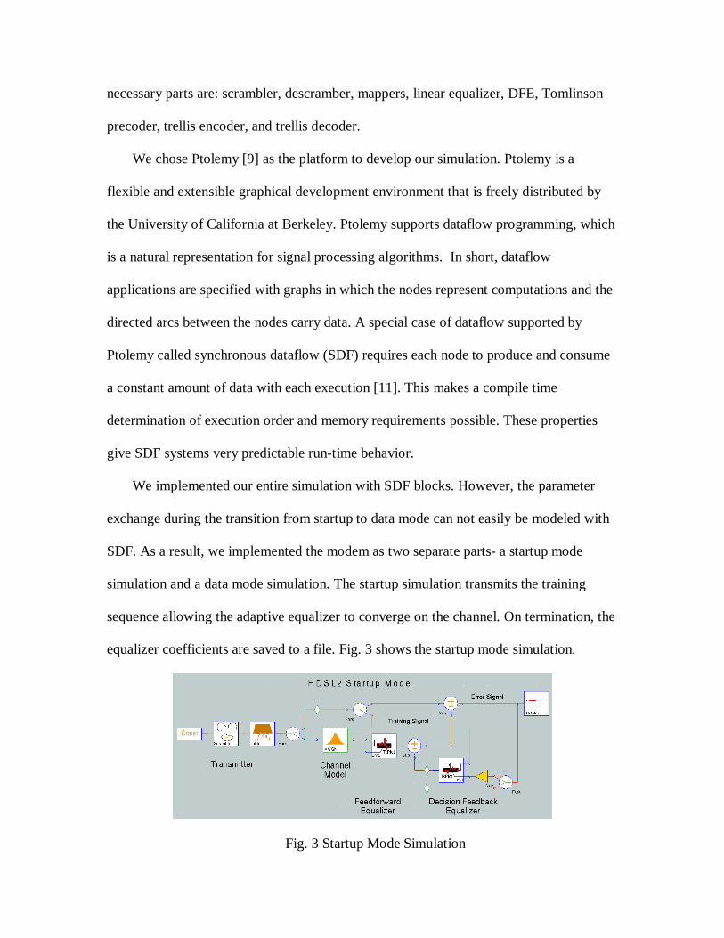
We implemented our entire simulation with SDF blocks. However, the parameter
exchange during the transition from startup to data mode can not easily be modeled with
SDF. As a result, we implemented the modem as two separate parts- a startup mode
simulation and a data mode simulation. The startup simulation transmits the training
sequence allowing the adaptive equalizer to converge on the channel. On termination, the
equalizer coefficients are saved to a file. Fig. 3 shows the startup mode simulation.
Fig. 3 Startup Mode Simulation

The data mode simulation uses the equalizer coefficients stored by the startup
execution to program the Tomlinson precoder. This simulates the transmission of these
parameters before the switch to data mode. Fig. 4 shows the data mode simulation
provisioned to count the number of bit errors encountered with a random binary input
stream over a channel with linear distortion and additive Guassian white noise.
Fig. 4 Data Mode Simulation
Fig. 5 shows the data mode configuration window. The window allows the user to
set, at run time, all the parameters necessary to perform trade-off analysis of the
programmable components. This is a particularly useful feature when developing the
Viterbi decoder because we expect it to represent approximately 85-90% of the
computational resources of the system.
Fig. 5 Data Mode Simulation Configuration Window

4 Limitations and Future Work
Several enhancements could be made to the simulation. An obvious improvement is
the combine the startup and data mode into a single simulation. Ptolemy supports the
mixing of SDF with a finite state machine (FSM) model of computation. With this
combination the startup to data mode transition logic could be added on top of the current
SDF blocks as an FSM process. Another consideration is the channel model. The model
used is a very simplified, stationary system. A time-varying model that simulates
crosstalk interference from other services as described in [2] would be more realistic. Our
simulation also assumes a synchronized transmitter and receiver so that both the spectral
shaper and the receiver front end can be left out. These would be useful additions.
Finally, the Tomlinson modulo operation is done before the trellis decoder in our receiver
simulation. For optimal performance, the modulo needs to be done in the decoder.
5 References
[1] J.W. Lechleider, “High Bit Rate Digital Subscriber Lines: A Review of HDSL Progress,” IEEEJournal on Selected Areas in Communications, vol. 9, no. 6, pp. 769-784, Aug. 1991.
[2] M. Rude, "Draft for HDSL2 Standard," ADC Telecommunications contribution, T1E1.4/99-006, Jan.1999.
[3] R. Goodson, K. Schneider, and J. Moore, “Proposal for Single-Loop HDSL Using Simple CodedPAM,” ADTRAN contribution, T1E1.4/96-037, Apr. 1996.
[4] R. Gaikwad and R. Baraniuk, “Optimal Transmit Spectra for HDSL2,” Rice University contribution,T1E1.4/98-162R1, Jun. 1998.
[5] E.A. Lee and D.G. Messerschimitt, Digital Communication, 2nd Edition, Kluwer Academic Publishers,ISBN 0-7923-9391-0, 1994.
[6] G.J. Pottie and M.V. Eyuboglu, “Combined Coding and Precoding for PAM and QAM HDSLSystems,” IEEE Journal on Selected Areas in Communications, vol. 9, no. 6, pp. 861-870, Aug. 1991.
[7] A.K. Aman, R.L. Cupo, and N.A. Zervos, “Combined Trellis Coding and DFE through TomlinsonPrecoding,” IEEE Journal on Selected Areas in Communications, vol. 9, no. 6, pp. 876-883, Aug.1991.
[8] A.J. Viterbi, "Convolutional Codes and Their Performance in Communications Systems," IEEETransactions on Communications, COM-19, pp. 750-772, Oct. 1971.
[9] J. Buck, S. Ha, E.A. Lee, and D.G. Messerschimitt, “Ptolemy: A Framework for Simulating andPrototyping Heterogeneous Systems,” International Journal of Computer Simulation, special issue onSimulation Software Development, vol. 4, 1994.
[10] E.A. Lee and D.G. Messerschmitt, “Synchronous Dataflow,” Proceedings of the IEEE, vol. 75, no. 9,1987.