Final Draft - Helmholtz-Zentrum Geesthacht Zentrum für … · · 2011-08-25Final Draft of the...
33
Final Draft of the original manuscript: Graff, S.; Brocks, W.; Steglich, D.: Yielding of Magnesium: From Single Crystal to Polycrystalline Aggregates In: International Journal of Plasticity (2007) Elsevier DOI: 10.1016/j.ijplas.2007.07.009
Transcript of Final Draft - Helmholtz-Zentrum Geesthacht Zentrum für … · · 2011-08-25Final Draft of the...

Final Draft of the original manuscript: Graff, S.; Brocks, W.; Steglich, D.: Yielding of Magnesium: From Single Crystal to Polycrystalline Aggregates In: International Journal of Plasticity (2007) Elsevier DOI: 10.1016/j.ijplas.2007.07.009
YIELDING OF MAGNESIUM: FROM SINGLE CRYSTAL TO POLYCRYSTALLINE AGGREGATES
Stéphane Graff, Wolfgang Brocks, Dirk Steglich
GKSS Research Centre, Institute for Materials Research,
D-21502 Geesthacht, Germany
[email protected] [email protected]
ABSTRACT - Hexagonal close-packed (hcp) metals show a deformation behavior, which is quite different from that of materials with cubic crystalline structure. As a consequence, rolled or extruded products of magnesium and its alloys exhibit a strong anisotropy and an unlike yielding in tension and compression. In this work, the microstructural mechanisms of deformation in pure magnesium are modeled by visco-plastic constitutive equations of crystal plasticity. Single crystals and textured polycrystals are analyzed numerically. By means of virtual mechanical tests of representative volume elements mesoscopic yield surfaces are generated. The linking of micro- and mesoscale provides a procedure for the simulation of the yielding and hardening behavior of arbitrarily textured solids with hcp structure such as extruded bars or rolled plates.
Keywords: hcp, magnesium, crystal plasticity, slip systems, twinning, yield surface
INTRODUCTION
Magnesium alloys have attracted attention in recent years as lightweight materials for the
transportation industry. Indeed, the low density of magnesium (1.74 g/cm3) and its
relatively high specific strength make it an excellent candidate for applications in
transportation industry, where saving of structural weight and reduction of fuel
consumption are common challenges, see e.g. Göken et al. (2002), Kainer (2003),

Neelameggham et al. (2005). A broad application of magnesium wrought alloys in
modern vehicles and consumer goods requires reliable simulation tools for predicting the
forming capabilities, the structural behavior under mechanical loads and the lifetime of
the component. The respective constitutive models have to account for several anomalies
of the mechanical behavior. Magnesium and its alloys show a pronounced strength
differential effect at low homologous temperatures: the tensile strength is much higher
than the strength in compression. Furthermore, magnesium exhibits a low ductility as
well as strong deformation anisotropy - both demand for non state-of-the-art simulation
techniques.
The mentioned mechanical anomalies of magnesium originate from its micromechanical
deformation mechanisms, which are determined by its hexagonal close-packed (hcp)
crystallographic structure. Metals with hcp crystalline structures hold a reduced number
of available slip systems compared to body-centered cubic (bcc) and face-centered cubic
(fcc) lattices, making plastic deformation more difficult. With the asymmetric
distribution of slip systems over the crystallographic reference sphere, various primary
and secondary slip and twinning mechanisms can and have to be be activated at the same
time. In contrast, in fcc metals usually only systems of one family become active.
Therefore, modelling of the macroscopic deformation of hcp materials requires a careful
investigation of the micromechanisms. Understanding the mechanisms of dislocation
gliding and deformation twinning for single crystals and polycrystalline aggregates
constitutes the fundament for modeling of the macroscopic mechanical behavior. To this
end, microstructural experimental observations, mechanical tests and numerical modeling
are combined.
Mechanical tests on single crystals of hcp metals for various crystallographic orientations
are sophisticated, and the respective literature is scarce. Wonsiewicz and Backofen
(1967) as well as Kelley and Hosford (1968a, b) conducted thorough channel-die (plane
strain) compression tests on Mg single crystals displaying its complex deformation
behavior and revealing the active slip and twinning systems. The data of Kelley and
Hosford are used in the present contribution to identify the model parameters of
constitutive equations based on crystal plasticity. After a short review of the crystal
plasticity model used, the identification of the respective model parameters is

emphasized. In the second part of the contribution, the parameters are applied for
predicting the mesoscopic behavior of polycrystalline representative volume elements
(RVEs). In this way the microscopic features developing during plastic deformation of
Mg are linked to the mesoscale and allow for the prediction of yielding behavior of
arbitrarily textured solids, for example extruded bars or rolled plates. RVE calculations
can be used to generate macroscopic yield surfaces.
Due to limitations in computational power, simulations of the structural behavior of
(macroscopic) polycrystalline structures cannot be performed effectively with models of
crystal plasticity. They require phenomenological constitutive equations, e. g. a plastic
potential and a flow rule to be used in the framework of rate dependent or rate
independent plasticity. The presented method can be used to calibrate parameters of a
plastic potential, namely the one recently proposed by Cazacu and Barlat (2004), which
accounts for anisotropy and tension/compression asymmetry.
MODELLING OF HCP METALS BY CRYSTAL PLASTICITY
Deformation Mechanisms in Magnesium
Planes and orientations of the hexagonal lattice are described here with the Miller-
Bravais indices related to a coordinate system of three basal vectors, , and the
longitudinal axis, c, which is the axis of hexagonal symmetry, see Fig. 1. Within this
system, four axes are used rather than three orthogonal ones. Dislocations in a hexagonal
lattice may be grouped in three families,
a1,a
2,a
3
a , c and a + c , depending on the
orientation of the slip plane and the slip directions, with the respective Burgers vectors of
lengths a, c and a2 + c2 . The basal plane is characterized by its normal vector
, the prismatic planes by n n = 0001 = 1100 and the pyramidal planes by
n = 1011 (π1), n = 1122 (π2) and n = 1012 (π3). The corresponding slip
directions are equivalent to m = 1120 for basal, prismatic and π1 slip. Straining in
direction of the c-axis can only be accommodated by c + a -systems, with a slip
direction of 3211 for the three pyramidal slip systems, π1, π2 and π3. Beside the
deformation caused by slip along crystallographic planes, deformation twinning is an
important deformation mechanism for hcp metals. It might be of tensile or compressive

nature, depending whether it results in an elongation or reduction or of the c-axis length.
Which of the possible mechanisms will occur depends on the material, the temperature
and on the strain rate. In the following, the authors focus on pure magnesium at room
temperature. Deformation will be applied in a quasistatic way, such that strain rate effects
are negligible.
The knowledge about the relevant deformation mechanism in magnesium has improved
over the years. In the first half of the last century the deformation mechanisms at low
homologous temperatures were found to be mainly basal slip and pyramidal twinning,
see Beck (1939). Later studies, realized in the 50’s and 60’s by Hauser et al. (1956),
Reed-Hill and Robertson (1957) as well as Yoshinaga et al. (1963) revealed prismatic
a slip systems to be another active slip mode at room temperature. Basal and prismatic
slip constitute only four independent shear systems which is not enough for
accommodating arbitrary plastic strain. The amount of observed (pyramidal) twinned
volume was found not to be sufficient for explaining the ductility of Mg at low
temperatures as discussed by Tegart (1964). Slip systems having a deformation
component in the c -direction were considered to play a role in plastic deformation:
Stohr and Poirier (1972), Obara et al. (1973) and later Ando and Tonda (2000) have
identified pyramidal
a + c as an active deformation mechanism at low homologous
temperatures.
Modeling activities for better understanding the features of plastic deformation in
magnesium alloys started recently and concentrate on the alloy AZ31 and its variation
AZ31B as the most common wrought magnesium alloys. Agnew et al. (2001) studied,
within others, the relation between mechanical behavior and texture evolution of AZ31B.
In order to reproduce similar textures than those observed experimentally, they had to
account for
a + c slip. Furthermore, the authors concluded that prismatic
a slip
should kept marginal for avoiding undesired effects in the simulated texture. Thus, they
have considered only basal, pyramidal a + c and tensile twinning on the π3-plane to
describe the mechanical behavior simulations of AZ31B. This limitation turned out to be
satisfying for simulating uniaxial compression tests of a plate for both, in-plane and
through-thickness orientations. In later studies, Agnew et al. (2003) and Agnew and
Duygulu (2005) added prismatic
a slip to the previous set of deformation modes. Non-
basal slip in
a direction has been shown to be necessary for modeling the in-plane
anisotropy of AZ31B rolled plates at low temperatures.
Staroselsky and Anand (2003) described the macroscopic mechanical behavior in tension
and compression as well as the respective texture evolution of AZ31B extruded rods and
rolled plates without considering any slip system having a deformation component
oriented in
c direction. The considered deformation mechanisms, basal, prismatic,
pyramidal
a and tensile twinning along the π3-plane, were enough to get good
agreement between experiment and simulation. The systematic texture simulations of
AZ31 conducted by Styczynski et al. (2004) showed that the best agreement between
simulated and experimental textures is obtained by considering basal, prismatic,
pyramidal
a + c and tensile twinning, which is the same as in Agnew et al. (2003) and
Agnew and Duygulu (2005). Yi et al. (2006) also studied magnesium alloy AZ31 for
understanding the relation between texture evolution and flow curves. The authors
selected all three
a slip modes: basal, prismatic, pyramidal, as well as tensile twin and
pyramidal
a + c -slip.
As a resume, the significant deformation mechanisms acting in Mg and its alloys are still
subjected to discussion. Generally, the use of any a and one a + c slip system family
additionally to basal and tensile twinning seems to be necessary. Since pyramidal
a
slip is equivalent to a combination of basal and prismatic a cross-slip, this particular
system will not be considered in the following calculations. The remaining primary
systems, i.e. basal
a , prismatic a , pyramidal a + c plus tensile twinning on
1012 are chosen here to model the mechanical behavior in the framework of crystal
plasticity. These families include three basal, three prismatic, six pyramidal and six
twinning systems. Table 1 summarizes the deformation modes (families of systems) used
in the following.

Table 1: Deformation modes considered in the present work
Name Number of Slip Systems
Plane Slip Direction
Basal
a 3 0001 1120
Prismatic
a 3 1100 1120
Pyramidal
a + c (π2) 6 1122 1123
Tensile Twin (π3) 6 1012 1011
Constitutive Formulations
The kinematical theory for the mechanics of crystals has been established in the
pioneering work of Taylor (1938) and the theory by Hill (1966), Rice (1971) , Hill and
Rice (1972). The model of crystal plasticity used here employs the framework of Peirce
et al. (1982) and Asaro (1983a, b). The implementation in the commercial finite element
code ABAQUS is based on the user-material routine of Huang (1991).
The lattice of a crystalline material undergoes elastic stretching, rotation and plastic
deformation. The latter is assumed to arise solely from crystalline slip. The total
deformation gradient F is decomposed as
, (1) F = F* ⋅ Fp
where pF denotes plastic shear of the material to an intermediate reference configuration
in which lattice orientation and spacing are the same as in the initial configuration, and
denotes stretching and rotation of the lattice. Superscript * always indicates
the lattice part of the kinematic quantities in the following.
* *= ⋅F V R*
The rate of change of pF is related to the slip rate ( )αγ of the α slip system by
p p 1 ( ) ( ) ( )α α α
α
γ−⋅ = ∑F F m n , (2)
where the sum ranges over all activated slips systems, and the unit vectors ( )αm , ( )αn are
the slip direction and the slip-plane normal, respectively, in both initial and intermediate
reference configurations, which transform to
(3) m*(α ) = F* ⋅ m(α ) , n*(α ) = n(α ) ⋅ F*−1
in the current deformed configuration, where
. (4) n*(α ) ⋅ m*(β ) = n(α ) ⋅ F*−1 ⋅ F* ⋅ m(β ) = n(α ) ⋅ m(β ) = δαβ
The velocity gradient in the current configuration is given by
. (5) 1−= ⋅ = +L F F D Ω
The symmetric stretching rate, D, and the skew vorticity or spin tensor, Ω, can be
decomposed into lattice and plastic parts
, (6) D = D* + Dp , Ω = Ω* + Ωp
with
* * * * 1 p p ( ) *( ) *(, )α α α
α
γ−+ = ⋅ + = ∑D F F D m nΩ Ω . (7)
The elastic properties are assumed to be unaffected by slip, i.e. the stress is determined
solely by F*. Thus, the stretching rate, D, is related to the Jaumann derivative of
Cauchy's stress tensor, T, by
T∇*
+ T 1 : D*( )= C : D* , (8)
where C is the tensor of elastic moduli. The Jaumann rate in eq. (8) is the corotational
stress rate on axes that rotate with the crystal lattice, which is related to the corotational
stress rate on axes rotating with the material by
. (9) ( ) (*
* * *∇ ∇
= − ⋅ + ⋅ = + − ⋅ − ⋅ −T T Ω T T Ω T Ω Ω T T Ω Ω )*
The crystalline slip is assumed to obey Schmid's law, i.e. the slipping rate ( )αγ depends
on T solely through Schmid's resolved shear stresses,
τ (α ) = n*(α ) ⋅ρ0
ρT ⋅ m*(α ) , (10)
where ρ0 and ρ are the mass densities in the reference and current states. The rate of

change of the resolved shear stresses is
( )*
( ) *( ) * * * *( ):α ατ∇⎡
= ⋅ + − ⋅ + ⋅ ⋅⎢⎣ ⎦
n T T 1 D D T T D m α⎤⎥ . (11)
According to Peirce et al. (1982), the constitutive equation of slip is assumed as a
viscoplastic power law,
( ) ( ) ( )
( ) ( ) ( )0 Y Y
signnα α α
α α α
γ τ τγ τ τ
⎛ ⎞= ⎜
⎝ ⎠⎟ , (12)
where ( )0αγ is a reference strain rate. ( )
Yατ characterizes the current strength of the α slip
system, and n is the rate sensitivity exponent. Strain hardening is characterized by the
evolution of the strengths
( )( ) ( )Y hα α
αββ
τ γ γ= ∑ , (13)
with hαβ being the self (α = β) and latent (α ≠ β) hardening moduli depending on Taylor's
cumulative shear strain on all slip systems,
( )
0
t
dα
α
γ γ= ∑∫ τ . (14)
Slip systems are grouped into four families (Table 1) where twinning is treated like slip,
see below. Interactions of the different active systems are handled with respect to the
families of systems, not the individual system. It is furthermore assumed that
( )γαα hh = and ( )γαβαβ hqh = , (15)
so that the hardening law can be written as
t
( ) ( ) ( )Y 0
0
h( ) q dα ααβ
α≠β
⎛ ⎞τ = τ + γ γ + γ τ⎜
⎝ ⎠∑∫ β
⎟ . (16)
with as integration constant. Hardening parameters as well as the values of
the interaction parameters q
( )0 Y (0)ατ τ=
αβ have to be calibrated by a fitting procedure considering
both, test results of single crystals as well as polycrystals.

Three different hardening laws are applied in the following, namely
• linear hardening,
h γ( )= h0 , (17)
• Voce hardening (Agnew et al., 2001, Yi et al., 2006),
⎟⎟⎠
⎞⎜⎜⎝
⎛−⎟⎟
⎠
⎞⎜⎜⎝
⎛−=
∞∞ τγ
ττ
γ 000 exp1)(
hhh , (18)
with τ∞ being the saturation stress,
• and particularly for deformation twinning,
⎪⎪⎩
⎪⎪⎨
⎧
>⎟⎟⎠
⎞⎜⎜⎝
⎛
≤
= −
ref
m
ref
ref
forh
forh
hγγ
γγ
γγ
γ 1
0
0
)( . (19)
The integrated functions of eqns. (17) – (19) presenting the different hardening
characteristics are shown in Figure 2. The specific hardening law of eq. (19) was used for
the description of deformation twinning in order to model the observed phenomenon of a
sudden stress increase due to saturation of twinning after a certain amount of strain has
been reached. Twinning is assumed to be geometrical irreversible and the respective
systems can be activated by either tension or compression of the c-axis, depending on
whether the deformation results in an elongation or a shortening of the c-orientation.
Physically it is connected with a lattice rotation of a finite domain. This effect is difficult
to realize within the framework of crystal plasticity. Hence, twinning is handled here as
additional slip mechanisms of the type 1012 1011 and the reorientation of
crystallographic planes due to rotation is not taken into account. This way of
representation for twinning assumes that, as twinning has saturated, further plastic
deformation issues only in the “untwinned” material. Furthermore, it is assumed that
both, slip and twinning, can operate simultaneously at a material point. Deformation
twinning modeled as crystallographic slip is supposed to follow Schmid’s law, see eqs.
(12) - (14). Its hardening law is assumed as in eq. (19), and the polar character of
twinning is taken into account with the restriction,
, (20) τ Y(α ) → ∞ for τ (α ) ≤ 0
allowing extension of the c-orientation (tensile twinning) only.
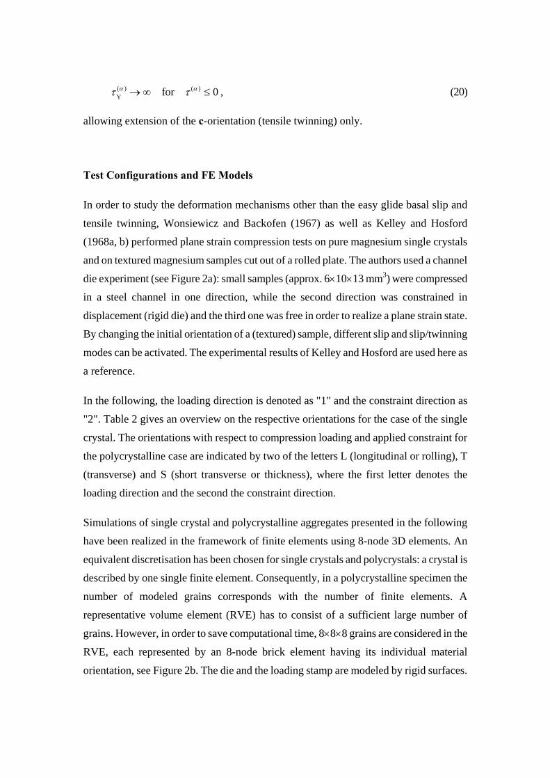
Test Configurations and FE Models
In order to study the deformation mechanisms other than the easy glide basal slip and
tensile twinning, Wonsiewicz and Backofen (1967) as well as Kelley and Hosford
(1968a, b) performed plane strain compression tests on pure magnesium single crystals
and on textured magnesium samples cut out of a rolled plate. The authors used a channel
die experiment (see Figure 2a): small samples (approx. 6×10×13 mm3) were compressed
in a steel channel in one direction, while the second direction was constrained in
displacement (rigid die) and the third one was free in order to realize a plane strain state.
By changing the initial orientation of a (textured) sample, different slip and slip/twinning
modes can be activated. The experimental results of Kelley and Hosford are used here as
a reference.
In the following, the loading direction is denoted as "1" and the constraint direction as
"2". Table 2 gives an overview on the respective orientations for the case of the single
crystal. The orientations with respect to compression loading and applied constraint for
the polycrystalline case are indicated by two of the letters L (longitudinal or rolling), T
(transverse) and S (short transverse or thickness), where the first letter denotes the
loading direction and the second the constraint direction.
Simulations of single crystal and polycrystalline aggregates presented in the following
have been realized in the framework of finite elements using 8-node 3D elements. An
equivalent discretisation has been chosen for single crystals and polycrystals: a crystal is
described by one single finite element. Consequently, in a polycrystalline specimen the
number of modeled grains corresponds with the number of finite elements. A
representative volume element (RVE) has to consist of a sufficient large number of
grains. However, in order to save computational time, 8×8×8 grains are considered in the
RVE, each represented by an 8-node brick element having its individual material
orientation, see Figure 2b. The die and the loading stamp are modeled by rigid surfaces.

Friction between the sample and the rigid surfaces is accounted for, assuming a Coulomb
friction coefficient of 0.05 for all tests. In case of the polycrystalline specimen, surfaces
in extension direction have not been constrained. All simulations assume isotropic
elasticity with Young’s modulus E=45000 MPa and Poisson ratio 3.0=ν . Since the
experiments have been performed with quasistatic loading, the strain rate sensitivity
exponent n in equation (12) is set equal to 50, making the simulation results almost rate
independent. The reference strain rate for each slip system, ( )0αγ , is chosen to be
compatible with the time scale in the FE simulations, and set to 10-3.
Table 2: Definition of the different orientations used with the plane-strain compression tests on single crystals by Kelley and Hosford (1968a)
test loading (1) constraint (2)
A 0 0 0 1 1 0 1 0
B 0 0 0 1 1 2 1 0
C 1 0 1 0 0 0 0 1
D 1 2 1 0 0 0 0 1
E 1 0 1 0 1 2 1 0
F 1 2 1 0 1 0 1 0
G 0 0 0 1 at 45° 1 0 1 0
In order to evaluate the mechanical response of single and polycrystals the following
definitions of true stresses and true (logarithmic) strains are respectively used,
011 11 11
11 0 011 11
ln ln 1⎛ ⎞ ⎛+ Δ Δ
= = +⎜ ⎟ ⎜⎝ ⎠ ⎝
l l ll l
ε⎞⎟⎠
, (21)
1111 0
0 1
1⎛ Δ
= +⎜⎝ ⎠1
⎞⎟
f lFA l
σ . (22)
Here, and are the RVE’s original length in loading direction and original section
with respect to loading direction, respectively. denotes the absolute value of the load
011l 0A
F
and is the friction correction coefficient introduced by Kelley and Hosford
(1968a,b). The above expression for true stresses is obtained in assuming constant
volume of the RVE during plastic deformation.
0.89=f
As in the channel die case, the simulations of uniaxial tension and compression tests in L,
T and S-direction were performed on polycrystalline aggregates of 8×8×8 solid elements
showing the same crystallographic orientations than presented in Fig. 5a. Periodic
boundary conditions were applied on the surfaces of the RVE. In order to simulate yield
loci and strain hardening in the (L,T)-plane, the plastic deformation of the same
polycrystalline aggregate is investigated under plane stress conditions performing radial
in-plane loading paths with different ratios of T L =arctanσ σ ρ , where ρ is the angle to
the rolling direction (L) of the plate. For each loading path, several unloading steps have
been realized in order to separate elastic and plastic mesoscopic strain.
Deformation of Single Crystals, Textured Polycrystals, and Parameter Identification
Establishing a model is the first significant step, determining its parameters is the second
and often more complex one. The more advanced and sophisticated material models are,
the more parameters do they include. Their identification requires inverse techniques, in
which numerical simulations are calibrated by test data. Various procedures exist for this
process, comprising manual fitting, trial and error, numerical optimization and neural
networks, see e.g. the review articles of Mahnken (2004), Brocks and Steglich (2006).
The determination of numerous parameters raises a lot of fundamental questions, namely
on the uniqueness of a parameter set, the sensitivity of the mechanical response to
variations of these parameters and the design of adequate tests capable of identifying
certain model parameter. Neither of these problems can be elaborated here, as the focus
is on the performance of the model and as test data had to be taken from literature. Based
on these data, parameter identification has been executed as a systematic trial and error,
yielding results that look reasonably but cannot claim to be the best possible fit. Though
optimization methods appear as appropriate for obtaining a "best fit", they lack any
physical background and evidence. Parameter identification in practice requires insight
knowledge of constitutive theories as well as experimental mechanics. Optimization

algorithms and software cannot replace this expertise.
Apart from the material constants for isotropic elasticity, namely Young’s modulus and
Poisson's ratio, the constitutive model presented above comprises three kinds of
parameters per slip system, α,
• two parameters of the viscoplastic law, ( )0αγ and n, eq. (12),
• between two and four hardening parameters, depending on the respective hardening law, τ0, τ∞, h0, γref, m, eqs. (17), (18), (19),
• parameters of latent hardening, describing the interaction between the various slip systems, qαβ, eq. (16).
For simplification, it has been assumed, that direct and latent hardening are identical for
all slip systems of each of the four basic mechanisms, namely basal slip, prismatic slip,
pyramidal slip and twinning. Linear hardening, eq. (17), with two parameters, τ0, h0, is
assumed for basal slip, Voce hardening, eq. (18), with three parameters, τ0, τ∞, h0, for
prismatic and pyramidal slip, and the combination of linear, τ0, h0, and power law
hardening, eq. (19), with two parameters, γref, m, for tensile twinning. This adds up to 2 +
2×3 + 4 = 12 parameters for direct hardening, see Table 3. Latent hardening is described
by 4 × 4 = 16 interaction parameters, qαβ, see Table 4.
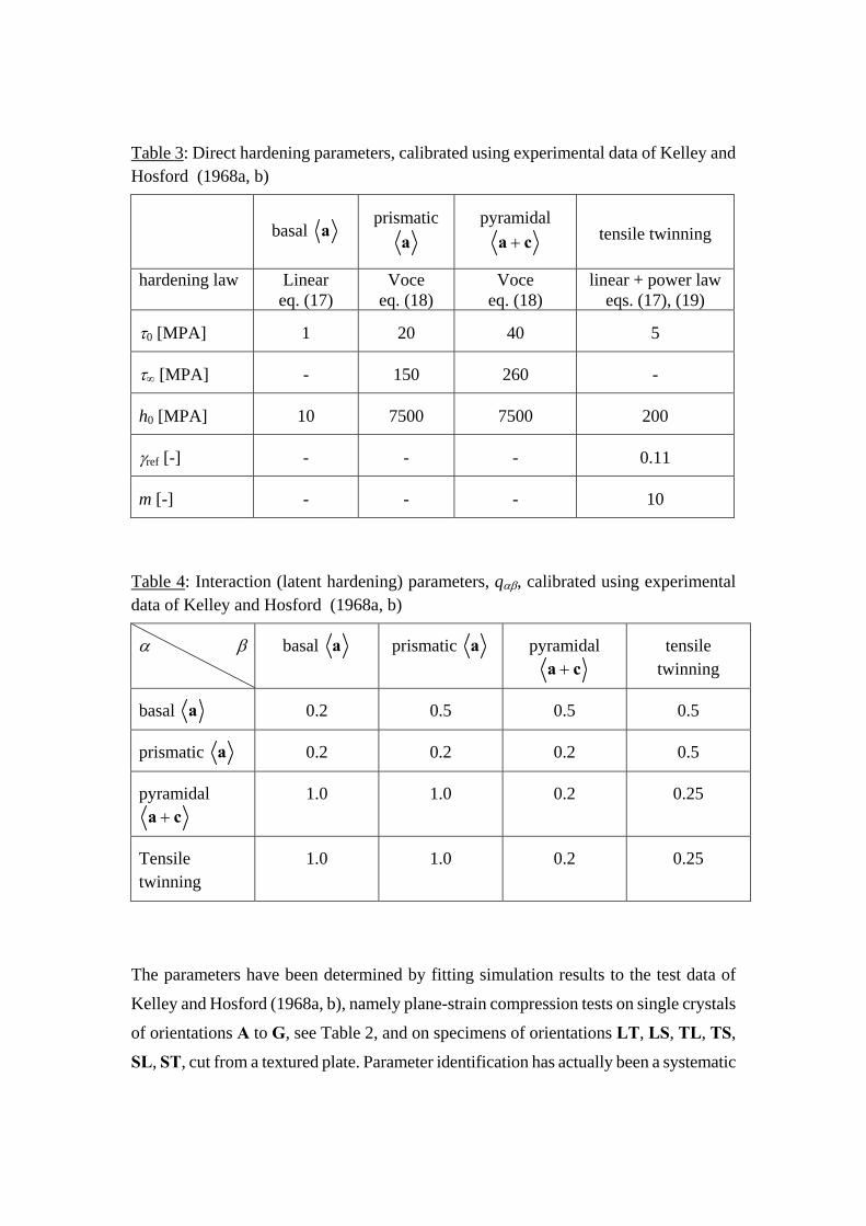
Table 3: Direct hardening parameters, calibrated using experimental data of Kelley and Hosford (1968a, b)
basal
a
prismatic
a
pyramidal
a + c tensile twinning
hardening law Linear eq. (17)
Voce eq. (18)
Voce eq. (18)
linear + power law eqs. (17), (19)
τ0 [MPA] 1 20 40 5
τ∞ [MPA] - 150 260 -
h0 [MPA] 10 7500 7500 200
γref [-] - - - 0.11
m [-] - - - 10
Table 4: Interaction (latent hardening) parameters, qαβ, calibrated using experimental data of Kelley and Hosford (1968a, b)
α β basal
a prismatic a pyramidal a + c
tensile twinning
basal
a 0.2 0.5 0.5 0.5
prismatic
a 0.2 0.2 0.2 0.5
pyramidal
a + c
1.0 1.0 0.2 0.25
Tensile twinning
1.0 1.0 0.2 0.25
The parameters have been determined by fitting simulation results to the test data of
Kelley and Hosford (1968a, b), namely plane-strain compression tests on single crystals
of orientations A to G, see Table 2, and on specimens of orientations LT, LS, TL, TS,
SL, ST, cut from a textured plate. Parameter identification has actually been a systematic

procedure of trial and error, benefiting from a deeper insight into deformation
mechanisms being active in the respective orientations of the single crystals. Different
deformation modes are activated in the single crystal tests depending on the respective
orientations of specimens. This allows for selectively identifying the hardening
parameters for a particular slip mechanism, provided that the respective mechanism is
exclusively activated in the model. This requires that the latent hardening parameters
have values different from zero. The discussion of the simulation results below will
elucidate this more clearly. The actual values of the latent hardening parameters cannot
be concluded from the single crystal tests, however, but calls for the polycrystal test
results. Due to the small number of grains used in the respective simulations and the
merely qualitative mapping of the texture, only approximate predictions of the
specimens' deformation behavior can be expected.
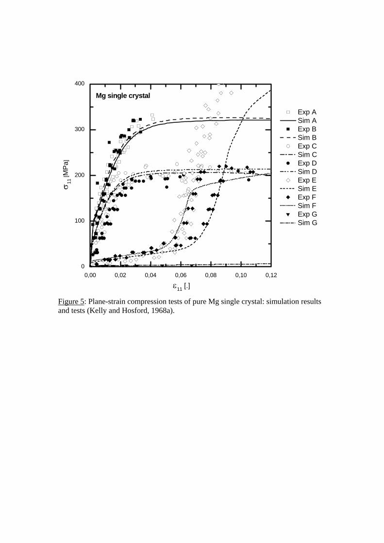
A comparison of simulation and test results for single crystals of orientations A to G, see
Table 2, is shown in Fig. 5. Beside a general qualitative agreement between experimental
and simulated results, the simulations capture the following specific features:
• Nearly identical stress-strain curves with high yield stress and strong hardening for
orientations A and B, where the loading direction is 0 0 0 1 ;
• Nearly identical stress-strain curves with - compared to A and B - lower yield stress
for orientations C and D, where the constraint direction is 0 0 0 1 ;
• Anomalous hardening behavior of orientations E and F with relatively low yield
stress and almost no hardening at strains smaller than 6%, followed by a sudden
increase in stress,
• Saturation stress of orientation E exceeding that of A and B.
• Saturation stress of orientation F about that of C and D.
• Very low stress level for orientation G.
The simulated stress increase in orientation F is delayed compared to that obtained in the
tests. As the simulations aimed at a unique set of model parameters, this deviation
between test results and model predictions has been accepted. Note also, that the

occurrence of stress rising for orientation E is not unambiguous in the tests, either.
Considering the general assumptions made with respect to the hardening laws and the
considerably large number of hardening parameters summarized in Table 3, the
accordance between test and simulation results is considered as quite good.
The numerical simulations allow also for an analysis of the slip mechanisms causing the
deformation of the single crystal samples. Fig. 6 shows the evolution of the relative
activities of the various slip systems with increasing strain for each test. Relative activity
indicates the contribution of a specific deformation mode to the plastic strain increment,
as the latter is set to 1. Assuming non-zero values for the latent hardening parameters, the
activation of the deformation modes for the different orientations occurs selectively.
Only the curves A and B show more than one family of slip mechanisms acting at the
same time, namely prismatic and pyramidal slip. Curves C and D are dominated by
prismatic slip and curve G by basal slip over the whole range of strain. For orientations E
and F the transition from twinning to pyramidal slip occurs within a very small range of
strains. Orientations E and F favor plastic deformation resulting in an elongation of the c-
axis. Because of its low critical resolved shear stress (CRSS), τ0, tensile twinning is
easily activated, and as saturation according to the power law eq. (19) occurs, elastic
deformation increases the stresses until they reach the CRSS of pyramidal glide, which
explains the sudden increase of stresses at about 0.06 strain in Fig. 5. This selectivity in
the activation of slip mechanisms facilitates an efficient determination of the CRSS and
the hardening parameter values of the different slip systems.
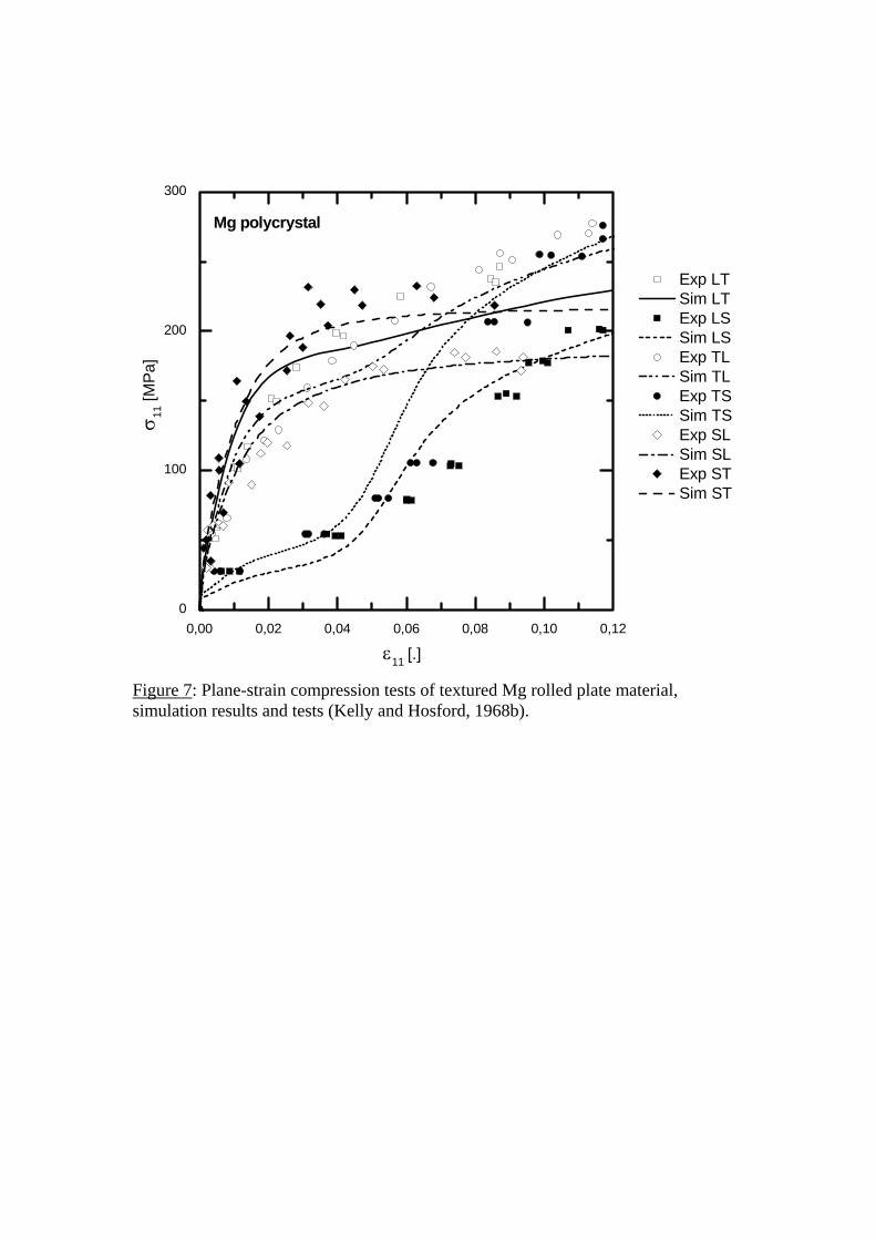
The comparison of Kelley and Hosford's (1968b) plane-strain compression tests on
polycrystalline samples with orientations LT, LS, TL, TS, SL, ST, cut out of Mg rolled
plates with the simulation results is depicted in Fig. 7. The two letters denote the
orientation with respect to the loading and the constraint direction, respectively; L is the
longitudinal or rolling direction, T the transverse and S the short transverse or thickness
direction. The general trend is well reproduced for all curves except for curve LT where
hardening is too small compared to the experimental data. Due to the rolling process, the
c-axes of the grains are orientated approximately parallel to the thickness direction of the
plate with a slightly higher deviation in rolling than in transverse direction. This
pronounced texture results in some qualitative similarities, of the flow curves between
single crystals, Fig. 5, and polycrystals, Fig. 7. Polycrystals of orientations LT, TL, ST,
SL show a monotonous hardening as the single crystals of orientations A, B, C, D. Those
of orientations TS and LS exhibit the same striking hardening behavior as the single
crystals of orientations E and F, namely relatively low yield stresses and little hardening
at strains smaller than 4%, followed by a sudden increase in stress. Some differences of
the hardening behavior of the polycrystals to that of single crystals are worth mentioning,
however. The texture difference between the L and T orientation of the polycrystals is
minor, see Fig. 4, which levels the differences between the respective curves in Fig. 7.
The saturation stresses reached in the polycrystal specimens of orientations ST and SL
are lower than those of the single crystals of orientations A, B , C and D, respectively,
and the differences in the stresses of LS and TS are smaller than those between E and F.
The curves A, B, C, D in Fig. 5 saturate, whereas the curves LT and TL in Fig. 7 do not.
The specific shapes of the flow curves can be understood by the analysis of activated slip
systems discussed below.
Despite the qualitative similarities in the hardening behavior between single crystals and
textured polycrystals, the test data from polycrystals have great importance for the
calibration of the material parameters, particularly the latent hardening parameters, qαβ.
Due to the varying orientations of grains in the RVE, more than one deformation mode
has to be activated at the same time. This is manifested by Fig. 7, which shows the
“integral” activity of the respective slip systems in the RVE. The above statement even
holds on the level of a material point, where (different from the single crystal case)
several slip mechanism are active. Hence, the latent hardening parameters affect the
macroscopic response of the sample significantly and have to be identified from the tests
on polycrystals rather than on single crystals.
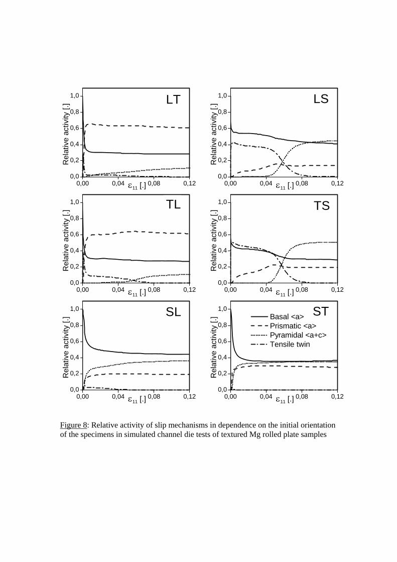
The relative activation of slip systems shown in Fig. 8 helps in understanding the flow
curves of Fig. 7. In the specimens of orientations LT and TL, about 60% of the plastic
deformation results from prismatic slip with Voce hardening (τ0 = 20 MPa,
τ∞ = 150 MPa), nearly 30% from basal slip with linear hardening (τ0 = 1 MPa). For the
specimens of orientations SL and ST, pyramidal (Voce hardening, τ0 = 40 MPa,
τ∞ = 260 MPa) and basal slip (linear hardening) contribute nearly equally by about 40%
and prismatic slip (Voce hardening, τ0 = 20 MPa , τ∞ = 150 MPa) by about 20%. The low
yield strength and hardening for the orientations LS and TS is due to the activation of
tensile twinning (τ0 = 5 MPa), which contributes to the plastic deformation by about
40%, and the sudden increase of stresses beyond 5% strain results from the saturation of
twinning going along with the activation of pyramidal slip.
Yield Surfaces of Polycrystals
Simulations of the structural behavior of polycrystals cannot be performed effectively
with crystal plasticity models on the microscale but require phenomenological
constitutive equations for yielding and hardening under multiaxial stress states. These
equations are established on a meso level. In micromechanical modeling, the transfer
from the micro to the mesoscale is performed by representative volume elements (RVEs),
which are designed to represent typical periodic microstructures of polycrystalline
materials.
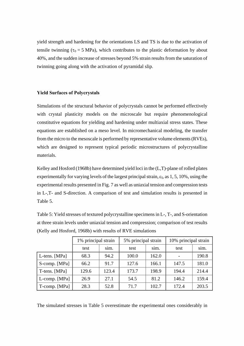
Kelley and Hosford (1968b) have determined yield loci in the (L,T)-plane of rolled plates
experimentally for varying levels of the largest principal strain, εI, as 1, 5, 10%, using the
experimental results presented in Fig. 7 as well as uniaxial tension and compression tests
in L-,T- and S-direction. A comparison of test and simulation results is presented in
Table 5.
Table 5: Yield stresses of textured polycrystalline specimens in L-, T-, and S-orientation
at three strain levels under uniaxial tension and compression; comparison of test results
(Kelly and Hosford, 1968b) with results of RVE simulations
1% principal strain 5% principal strain 10% principal strain test sim. test sim. test sim.
L-tens. [MPa] 68.3 94.2 100.0 162.0 - 190.8 S-comp. [MPa] 66.2 91.7 127.6 166.1 147.5 181.0 T-tens. [MPa] 129.6 123.4 173.7 198.9 194.4 214.4 L-comp. [MPa] 26.9 27.1 54.5 81.2 146.2 159.4 T-comp. [MPa] 28.3 52.8 71.7 102.7 172.4 203.5
The simulated stresses in Table 5 overestimate the experimental ones considerably in

almost all loading configurations and at all strain levels. This appears very much like a
systematic error, too pronounced for being wiped off. The effect of boundary conditions
and friction has been investigated by the authors and found to be of less significance.
Any other explanation for the observed misfit is still missing. Nevertheless, the two most
notable aspects of the yield behavior for magnesium plates are reproduced by the
simulations, namely anisotropy and tension/compression asymmetry. In view of a
number of approximations and imponderabilities in the simulations, particularly with
respect to the parameter identification and the mapping of the texture, as well as possible
uncertainties in the evaluation of the test data, the coincidence of experimental and
numerically simulated tests is satisfying and encouraging for the generation of
qualitatively realistic yield surfaces of the plate material.
Fig. 9 shows subsequent yield surfaces for mesoscopic stresses under increasing
equivalent plastic strain from pε = 0.01 to 0.10 with an increment of 0.01. Though the
authors are aware that von Mises equivalent strain is obviously not an appropriate
measure for characterizing the mesoscopic hardening, they chose it nevertheless lacking
a more adequate one. At low values of plastic strain the RVE exhibits a strong anisotropy
and a high asymmetry of yielding between tension and compression while, with
increasing plastic strain the anisotropy and yielding asymmetry reduce considerably.
The evolution of the accumulated shear strain of the four slip systems in the RVE is
presented in Fig.10 in dependence on the angle, ρ , of the loading path. The contributions
of basal and prismatic slip oscillate with a period of approximately 180° and a phase shift
of about 90° to each other. Both deformation modes act equally in tension and
compression. The phase shift of 90° points out that both, basal and prismatic slip act in
a direction and compete with each other. Even though the texture of a rolled plate is
not actually favorable for basal slip, it is, in average over the whole range [ ]0 ,360∈ ° °ρ ,
the most active deformation mode due to its extremely low CRSS. Interestingly, the
relative contribution of basal slip to the accumulated shear strain tends to decrease with
increasing strain while that of the prismatic slip tends to increase. This is probably also
related to difference in CRSS for both deformation mechanisms implying that basal slip
is more active at the beginning of the deformation, where stresses are lower, than at the
end, and prismatic slip becomes more active at higher strains. As expected, tensile twin is

activated between 120° < ρ < 330°, only, where compression is present and, due to the
texture, elongation in c-direction is favored. The highest twinning activity is concentrated
in the range between 180° < ρ < 270°, where compression states exist in both
longitudinal and tangential direction of the plate. Pyramidal slip is significantly active in
the range between 0° < ρ < 90°, where shortening along the c-axis is favored. Following
the same principle as in orientations E and F in Fig. 5, as well as LS and TS in Fig. 7,
pyramidal slip +a c between 120° < ρ < 330°, is absent at low strains and activated at
higher strains once twinning saturates.
Phenomenological Yield Potential
As stated above, phenomenological constitutive equations for yielding and hardening are
required for simulations of the macroscopic structural behavior. The numerially
generated isocontours shown in Fig. 9, have hence to be fitted by an analytical expression
of the yield potential and an evolution equation for this yield potential has to be
established. A phenomenological yield potential for textured magnesium has to account
for both anisotropy and tension/compression asymmetry. Hill (1948, 1950) has
generalized the von Mises (1913) criterion for anisotropic materials. It predicts yield loci,
however, which are centered about the origin, and is hence not suited for hcp metals
deforming primarily by twinning. Accounting for the asymmetry of yielding in tension
and compression, that is shifting the center of the yield surface out of the origin of the
deviatoric plane, requires including the third invariant of the stress tensor (Drucker,
1949),
( )3
0 0 022 3≡ − = Yf J cJ 3τ . (23)
Cazacu and Barlat (2004) have shown, that this yield criterion describes well the
asymmetry of yielding due to activation of twinning. and are generalizations of the
second and third invariant of the stress tensor for orthotropic materials, containing 6 and
11 model parameters, respectively, in the general three-dimensional case. The total
number of model parameters reduces to 7 in the plane stress case. Different from the
yield criteria of von Mises and Hill, convexity of the yield surface is not a priori ensured
and has therefore to be introduced as an additional side condition, while identifying the
02J 0
3J

respective parameters, in order to fulfill Drucker’s postulate of material stability
(Drucker, 1964). The respective investigations based on the micromechanically yield
surfaces of Fig. 9 are in progress.
CONCLUSIONS
A crystal plasticity model has been used to study the deformation mechanisms of an hcp
metal. Simulations of plane-strain compression tests and uniaxial tension and
compression tests revealed that the experimentally observed phenomena of magnesium
and its alloys, namely a strong anisotropy and a significant tension/compression
asymmetry, can be understood considering four deformation mechanisms and their
activation: three basal slip systems, three prismatic slip systems, six pyramidal slip
systems and six tensile twinning systems. Twinning has clearly been identified for being
responsible for the tension-compression asymmetry which is observed in textured rolled
plates. Material parameters have been calibrated based on single crystal and polycrystal
experiments.
Once the material parameters of crystal plasticity have been identified, they can be used
for predicting the mechanical response of arbitrarily textured polycrystalline materials by
building aggregates of single crystals. The respective transfer from the microstructure to
a phenomenological representation of yielding of polycrystalline samples has been
successfully verified. Establishing a phenomenological yield potential and a respective
hardening rule for hcp materials is the future step in the modeling chain. The presented
methodology links investigations on the micro-level with simulation techniques used on
the lengthscale of engineering structures. Hence it can be understood as a link between
micro- and macromechanics.
Acknowledgement
The authors acknowledge W. Hosford’s support while providing the primary data of his
pioneering experimental work on pure magnesium.
REFERENCES:
Agnew, S. R., Duygulu, ö., 2005. Plastic anisotropy and the role of non-basal slip in magnesium alloy AZ31B 21. Int. J. Plasticity 21, 1161-1193.
Agnew, S. R., Tomé, C. N., Brown, D. W., Holden, T. M., Vogel, S. C., 2003. Study of slip mechanisms in a magnesium alloy by neutron diffraction and modeling. Scripta Materialia 48, 1003-1008
Agnew, S. R., Yoo, M. H., Tomé, C. N., 2001. Application of texture simulation to understanding mechanical behavior of Mg and solid solution alloys containing Li or Y. Acta Mater. 49, 4277-4289
Ando, S., Tonda, H., 2000. Non-basal slip in magnesium-lithium alloy single crystals, Mater. Trans. JIM 41, 1188-1191
Asaro, R.J., 1983, Crystal plasticity. J. Appl. Mech. 50, 921-934
Asaro, R. J., 1983. Micromechanics of crystals and polycrystals. Adv. Appl. Mech. 23, 1-115
Beck, A., 1939. Magnesium und seine Legierungen, Springer, Berlin
Brocks, W. , Steglich, D. (2006). Hybrid methods. In: Comprehensive Structural Inte-grity - Fracture of Materials from Nano to Macro, Volume 11: Mechanical Characteri-zation of Structural Materials, Elsevier, to be published
Cazacu, O., Barlat, F., 2004. A criterion for description of anisotropy and yield differential effects in pressure insensitive materials. Int. J. Plasticity 20, 2027-2045
Drucker, D. C., 1949. Relation of experiments to mathematical theories of plasticity. J. Appl. Mech. 16, 349-357
Drucker, D. C., 1964. On the postulate of stability of material in the mechanics of continua. Journal de Mécanique 3, 235-249
Göken, J., Bohlen, J., Letzig, D., Brokmeier, H.-G., Kainer, K.-U., 2002. Mg-Feinbleche für den Ultraleichtbau in der Verkehrstechnik. In: Kaufmann H., Uggowitzer, J. P., Wahlen, A., (Eds.), 2 Ranshofener Leichtmetalltage 2002 - Vom Werkstoff zum Bauteilsystem, LKR-Verlag, 229-240
Hauser, F. E., Landon, P. R., Dorn, J. E., 1956. Deformation and fracture mechanisms of polycrystalline magnesium at low temperatures. Transactions of the ASM 48, 986-1002
Hill, R., 1966. Generalized constitutive relations for incremental deformation of metal
crystals by multislip. J. Mech. Phys. Solids 15, 95-102
Hill, R., 1948. A theory of the yielding and plastic flow of anisotropic metals, Proc. R. Soc. Lond. A 193, p. 281-297
Hill, R., 1950. The Mathematical Theory of Plasticity, Oxford University Press (Chapter XII), 317-340
Hill, R., Rice, J. R., 1972. Constitutive analysis of elastic-plastic crystals at arbitrary strain. J. Mech. Phys. Solids 20, 401-413
Huang, Y., 1991. A user-material subroutine incorporating single crystal plasticity in the ABAQUS finite element program, Report MECH-178. Div. Applied Science, Harvard University, Cambridge (MA)
Kainer, K.-U., (Ed.), 2003. Magnesium Alloys and Their Applications, Wiley-VCH, Weinheim
Kelley, E. W., Hosford, W. F., 1968a. Plane-strain compression of magnesium and magnesium alloy crystals. Transactions of the metallurgical society of AIME 242, 5-13
Kelley, E.W., Hosford, W.F., 1968b. The deformation characteristics of textured magnesium. Transactions of the metallurgical society of AIME 242, 654-661
Mahnken, R. (2004). Identification of material parameters for constitutive equations. In: Encyclopedia of Computational Mechanics (ed. E. Stein, R. de Borst and Th.J.R. Hughes) John Wiley & Sons, Chichester , 637-655
Neelameggham, N. R., Kaplan, H. I., Powell, B. R., (Eds.), 2005. Magnesium Technology 2005, Publication of TMS
Obara, T., Yoshinga, H., Morozumi, S., 1973. 1122 1123 slip system in magnesium.
Acta Metall. 21, 845-853
Peirce, D., Asaro, R. J., and Needleman, A., 1982. An analysis of nonuniform and localized deformation in ductile single crystals. Acta Met. 30, 1082-1119
Reed-Hill, R. E., Robertson, W. D., 1957. Deformation of magnesium single crystals by non basal slip. Journal of metals. Transactions AIME, 496-502
Rice, J. R., 1971. Inelastic constitutive relations for solids: an internal variable theory and its application to metal plasticity. J. Mech. Phys. Solids 19, 433-455
Staroselsky, A., Anand, L., 2003. A constitutive model for hcp materials deforming by

slip and twinning: application to magnesium alloy AZ31B. Internationnal Journal of Plasticity 19, 1843-1864
Styczynski, A., Hartig, Ch., Bohlen, J., Letzig, D., 2004. Cold rolling textures in AZ31 wrought magnesium alloy. Scripta Materialia 50, 943-947
Stohr, J. F., Poirier, J. P., 1972. Etude en microscopie electronique du glissement pyramidal (11-22) (11-23) dans le magnesium, Phil. Mag. 25, 1313-1329
Taylor, G. I., 1938. Plastic strain in metals. J. Inst. Metals 62, 307-324
Tegart, W. J. McG., 1964. Independent Slip Systems and Ductility of Hexagonal Polycrystals. Phil. Mag. 9, 339-341
von Mises, R., 1913. Die Mechanik der festen Körper im plastischen deformablen Zustand. Nachr. Ges. Wiss., Göttingen, 582-592
von Mises, R., 1928. Mechanik der plastischen Formänderung von Kristallen. Z. angew. Math. u. Mech. 8, 161-185
Wonsiewicz, B. C., Backofen, W. A., 1967. Plasticity of magnesium crystals. Transactions of the metallurgical society of AIME 239, 1422-1431
Yi, S. B., Davies, C. H. J., Brokmeier, H.-G., Bolmaro, R. E., Kainer, K.-U., Homeyer, J., 2006. Deformation and texture evolution in AZ31 magnesium alloy during uniaxial loading. Acta Materialia 54, 549-562
Yoshinaga, H., Horiuchi, R., 1963. On the nonbasal slip in magnesium crystals. Trans. JIM 5, 14-21

FIGURES
Figure 1: Slip planes in hcp material: basal and prismatic planes (left), pyramidal (π1:
0111 , π2:
1122 , π3:
1012 ) planes (right)
Figure 2: Hardening laws used in the present investigations

Figure 3: Plane-strain compression test: principle (a) and FE model of a polycrystal (b)
TRANSVERSEDIRECTION
ROLLINGDIRECTION
a) b)
Figure 4: Experimental (Kelly and Hosford, 1968b) (a) and simulated (0001) pole figures (b) of pure magnesium rolled plate material
0,00 0,02 0,04 0,06 0,08 0,10 0,120
100
200
300
400
σ11
[MP
a]
ε11 [.]
Exp A Sim A Exp B Sim B Exp C Sim C Exp D Sim D Exp E Sim E Exp F Sim F Exp G Sim G
Mg single crystal
Figure 5: Plane-strain compression tests of pure Mg single crystal: simulation results and tests (Kelly and Hosford, 1968a).

0,00 0,04 0,08 0,120,0
0,2
0,4
0,6
0,8
1,0
0,00 0,04 0,08 0,120,0
0,2
0,4
0,6
0,8
1,0
0,00 0,04 0,08 0,120,0
0,2
0,4
0,6
0,8
1,0
0,00 0,04 0,08 0,120,0
0,2
0,4
0,6
0,8
1,0
0,00 0,04 0,08 0,120,0
0,2
0,4
0,6
0,8
1,0
0,00 0,04 0,08 0,120,0
0,2
0,4
0,6
0,8
1,0
0,00 0,04 0,08 0,120,0
0,2
0,4
0,6
0,8
1,0
R
elat
ive
activ
ity [.
]
ε11 [.]
Rel
ativ
e ac
tivity
[.]
ε11 [.]
Rel
ativ
e ac
tivity
[.]
ε11 [.]
Rel
ativ
e ac
tivity
[.]
ε11 [.]
Rel
ativ
e ac
tivity
[.]
ε11 [.]
Rel
ativ
e ac
tivity
[.]
ε11 [.]
G
FE
D
A
C
B
Basal <a> Prismatic <a> Pyramidal <a+c> Tensile twin
Rel
ativ
e ac
tivity
[.]
ε11 [.]
Figure 6: Relative activity of slip mechanisms in dependence of the initial crystallographic orientation of the specimens in simulated channel die tests of Mg single crystals
0,00 0,02 0,04 0,06 0,08 0,10 0,120
100
200
300
Mg polycrystal
σ 11
[MPa
]
ε11 [.]
Exp LT Sim LT Exp LS Sim LS Exp TL Sim TL Exp TS Sim TS Exp SL Sim SL Exp ST Sim ST
Figure 7: Plane-strain compression tests of textured Mg rolled plate material, simulation results and tests (Kelly and Hosford, 1968b).
0,00 0,04 0,08 0,120,0
0,2
0,4
0,6
0,8
1,0
0,00 0,04 0,08 0,120,0
0,2
0,4
0,6
0,8
1,0
0,00 0,04 0,08 0,120,0
0,2
0,4
0,6
0,8
1,0
0,00 0,04 0,08 0,120,0
0,2
0,4
0,6
0,8
1,0
0,00 0,04 0,08 0,120,0
0,2
0,4
0,6
0,8
1,0
0,00 0,04 0,08 0,120,0
0,2
0,4
0,6
0,8
1,0
R
elat
ive
activ
ity [.
]
ε11 [.]
LS
STSL
TSTL
LT
Rel
ativ
e ac
tivity
[.]
ε11 [.]
Rel
ativ
e ac
tivity
[.]
ε11 [.]
Rel
ativ
e ac
tivity
[.]
ε11 [.]
Rel
ativ
e ac
tivity
[.]
ε11 [.]
Basal <a> Prismatic <a> Pyramidal <a+c> Tensile twin
Rel
ativ
e ac
tivity
[.]
ε11 [.]
Figure 8: Relative activity of slip mechanisms in dependence on the initial orientation of the specimens in simulated channel die tests of textured Mg rolled plate samples

-300 -200 -100 0 100 200 300-300
-200
-100
0
100
200
300
σ T [M
Pa]
σL [MPa]
isostraincontours
Figure 9: Iso-contours of current mesoscopic yield stress of a textured polycrystalline RVE under plane-stress biaxial loading ( pε =0.01, …, 0.1)

0 90 180 270 3600,0
0,2
0,4
0,6
0,8
Basal <a> Prismatic <a> Pyramidal <a> Tensile twin εP = 0.01
εP = 0.05
εP = 0.10
R
elat
ive
accu
mul
ated
she
ar s
train
[.]
ρ [degree]
Figure 10: Contributions of crystallographic deformation modes at 0.01, 0.05, and 0.1 equivalent plastic strain for plane-stress biaxial loading of a textured polycrystalline RVE