Final Design
16
Chapter 4 Site Investigation Manual - 2002 Final Design Ethiopian Roads Authority Page 4-1 4. FINAL DESIGN 4.1 General Investigations for obtaining the geotechnical data that are necessary for designing a particular project should be based on the information obtained during the feasibility study and preliminary design. Data obtained during the feasibility study and preliminary design should be interpreted and the findings applied to optimize the investigations for design in terms of cost and time. Subsurface exploration procedures cannot be reduced to a few guidelines that fit all conditions. Widely diverse geologic environments, local equipment, personal preferences and time and budget constraints have all contributed to the development of different approaches. As mentioned in Chapter 2, investigations for design are often conducted in two stages (feasibility and preliminary stage, final stage), depending on the terms of reference. Where two stages are chosen or specified, the frequency of sampling and testing during the preliminary stage is significantly less that that for the final design. An indication of the types of tests and testing frequency for preliminary design is given in Table 4-1. Normally, the feasibility study and preliminary design have identified a final alignment, and the final stage of design is therefore aimed at defining precisely the earthworks, pavements and structures including their foundations, as well as the sources of materials. However, it is time-consuming and costly to mobilize a full fleet of field personnel and equipment twice to do the investigations. Thus, conversely, the preliminary stage investigation may often be the main investigation program. The final investigation program in this instance will be limited and directed only towards confirming design evaluations (particularly when there have been design changes subsequent to the main exploration program), for fine-tuning the decision analysis and for any specific problem areas along the alignment. If the investigations are to be done in two stages, with more or less equal emphasis, the specified sampling frequency for each stage is to be followed. However, if major emphasis is on the preliminary stage, then the frequency as recommended for the final stage needs to be adopted (see Table 4-1). The field exploration should be of such extent as to have sufficient data for final design. The explorations and testing, should serve the obvious needs of civil and structural design. The final design phase data must have sufficient accuracy, coverage and applicability to support design analysis and decisions. It should also permit reasonably accurate final estimates of material quantities and construction costs. In general, structural foundations have individually planned explorations. If feasible, depending on the size of the structure and project schedule, these investigations may also be combined with the main program.
-
Upload
haftamu-tekle -
Category
Documents
-
view
3 -
download
0
description
manual
Transcript of Final Design
Chapter 4Site Investigation Manual - 2002 Final Design
Ethiopian Roads Authority Page 4-1
4. FINAL DESIGN
4.1 General
Investigations for obtaining the geotechnical data that are necessary for designing aparticular project should be based on the information obtained during the feasibility studyand preliminary design. Data obtained during the feasibility study and preliminary designshould be interpreted and the findings applied to optimize the investigations for design interms of cost and time.
Subsurface exploration procedures cannot be reduced to a few guidelines that fit allconditions. Widely diverse geologic environments, local equipment, personal preferencesand time and budget constraints have all contributed to the development of differentapproaches.
As mentioned in Chapter 2, investigations for design are often conducted in two stages(feasibility and preliminary stage, final stage), depending on the terms of reference.Where two stages are chosen or specified, the frequency of sampling and testing duringthe preliminary stage is significantly less that that for the final design. An indication ofthe types of tests and testing frequency for preliminary design is given in Table 4-1.
Normally, the feasibility study and preliminary design have identified a final alignment,and the final stage of design is therefore aimed at defining precisely the earthworks,pavements and structures including their foundations, as well as the sources of materials.
However, it is time-consuming and costly to mobilize a full fleet of field personnel andequipment twice to do the investigations. Thus, conversely, the preliminary stageinvestigation may often be the main investigation program. The final investigationprogram in this instance will be limited and directed only towards confirming designevaluations (particularly when there have been design changes subsequent to the mainexploration program), for fine-tuning the decision analysis and for any specific problemareas along the alignment.
If the investigations are to be done in two stages, with more or less equal emphasis, thespecified sampling frequency for each stage is to be followed. However, if majoremphasis is on the preliminary stage, then the frequency as recommended for the finalstage needs to be adopted (see Table 4-1).
The field exploration should be of such extent as to have sufficient data for final design.The explorations and testing, should serve the obvious needs of civil and structuraldesign. The final design phase data must have sufficient accuracy, coverage andapplicability to support design analysis and decisions. It should also permit reasonablyaccurate final estimates of material quantities and construction costs.
In general, structural foundations have individually planned explorations. If feasible,depending on the size of the structure and project schedule, these investigations may alsobe combined with the main program.
Chapter 4Final Design Site Investigation Manual - 2002
Page 4-2 Ethiopian Roads Authority
The investigations for any typical project can broadly be categorized as:
• Earthwork and subgrade soils• Construction materials• Foundations of structures
4.2 Earthworks and Subgrade Soils
Investigation of earthworks and subgrade soils may be divided into two generalcategories:
• Common Investigations• Special investigations
4.3 Common Investigations: New Roads
4.3.1 SAMPLING AND FREQUENCY
Common investigations should cover basic data collection, such as depth and nature ofsoils (subgrade and embankment materials), and should be limited to test pits and handaugers. The common investigations can be for new roads and/or existing roads.
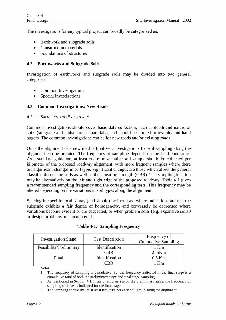
Once the alignment of a new road is finalized, investigations for soil sampling along thealignment can be initiated. The frequency of sampling depends on the field conditions.As a standard guideline, at least one representative soil sample should be collected perkilometer of the proposed roadway alignment, with more frequent samples where thereare significant changes in soil type. Significant changes are those which affect the generalclassification of the soils as well as their bearing strength (CBR). The sampling locationmay be alternatively on the left and right edge of the proposed roadway. Table 4-1 givesa recommended sampling frequency and the corresponding tests. This frequency may bealtered depending on the variations in soil types along the alignment.
Spacing in specific locales may (and should) be increased where indications are that thesubgrade exhibits a fair degree of homogeneity, and conversely be decreased wherevariations become evident or are suspected, or when problem soils (e.g. expansive soils0or design problems are encountered.
Table 4-1: Sampling Frequency
Investigation Stage Test DescriptionFrequency of
Cumulative SamplingFeasibility/Preliminary Identification
CBR1 Km
2 -5KmFinal Identification
CBR0.5 Km1 Km
Notes:1. The frequency of sampling is cumulative, i.e. the frequency indicated in the final stage is a
cumulative total of both the preliminary stage and final stage sampling.2. As mentioned in Section 4.1, if major emphasis is on the preliminary stage, the frequency of
sampling shall be as indicated for the final stage.3. The sampling should insure at least two tests per each soil group along the alignment.
Chapter 4Site Investigation Manual - 2002 Final Design
Ethiopian Roads Authority Page 4-3
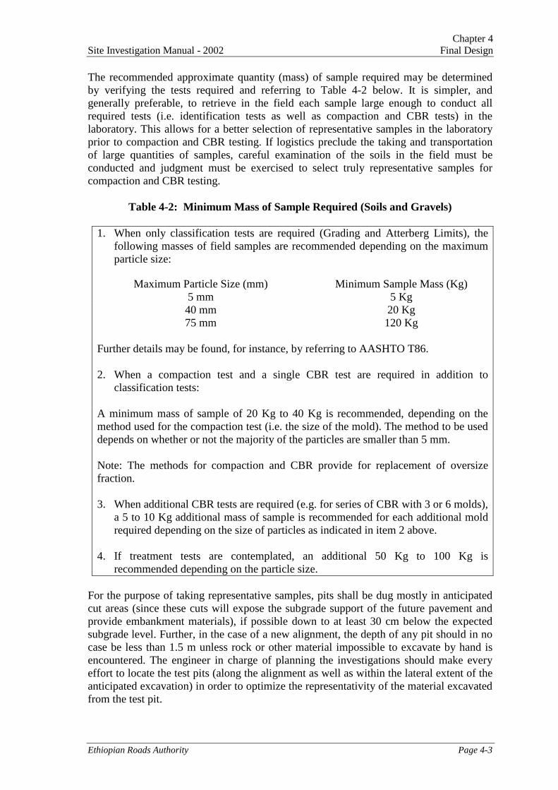
The recommended approximate quantity (mass) of sample required may be determinedby verifying the tests required and referring to Table 4-2 below. It is simpler, andgenerally preferable, to retrieve in the field each sample large enough to conduct allrequired tests (i.e. identification tests as well as compaction and CBR tests) in thelaboratory. This allows for a better selection of representative samples in the laboratoryprior to compaction and CBR testing. If logistics preclude the taking and transportationof large quantities of samples, careful examination of the soils in the field must beconducted and judgment must be exercised to select truly representative samples forcompaction and CBR testing.
Table 4-2: Minimum Mass of Sample Required (Soils and Gravels)
1. When only classification tests are required (Grading and Atterberg Limits), thefollowing masses of field samples are recommended depending on the maximumparticle size:
Maximum Particle Size (mm) Minimum Sample Mass (Kg)5 mm 5 Kg40 mm 20 Kg75 mm 120 Kg
Further details may be found, for instance, by referring to AASHTO T86.
2. When a compaction test and a single CBR test are required in addition toclassification tests:
A minimum mass of sample of 20 Kg to 40 Kg is recommended, depending on themethod used for the compaction test (i.e. the size of the mold). The method to be useddepends on whether or not the majority of the particles are smaller than 5 mm.
Note: The methods for compaction and CBR provide for replacement of oversizefraction.
3. When additional CBR tests are required (e.g. for series of CBR with 3 or 6 molds),a 5 to 10 Kg additional mass of sample is recommended for each additional moldrequired depending on the size of particles as indicated in item 2 above.
4. If treatment tests are contemplated, an additional 50 Kg to 100 Kg isrecommended depending on the particle size.
For the purpose of taking representative samples, pits shall be dug mostly in anticipatedcut areas (since these cuts will expose the subgrade support of the future pavement andprovide embankment materials), if possible down to at least 30 cm below the expectedsubgrade level. Further, in the case of a new alignment, the depth of any pit should in nocase be less than 1.5 m unless rock or other material impossible to excavate by hand isencountered. The engineer in charge of planning the investigations should make everyeffort to locate the test pits (along the alignment as well as within the lateral extent of theanticipated excavation) in order to optimize the representativity of the material excavatedfrom the test pit.
Chapter 4Final Design Site Investigation Manual - 2002
Page 4-4 Ethiopian Roads Authority
If deep cuts are proposed through materials indicated to be variable by test pits and astudy of the geological maps, consideration is to be given to drilling the cuts at the finaldesign stage when the potential hard stone sources are being investigated.
The position (in plan and elevation) of each test pit must be accurately determined andrecorded. This implies that geotechnical and topographical tasks must be coordinated inthe field. In every test pit, all layers, including topsoil, shall be accurately described andtheir thicknesses measured. All layers of more than 30 cm (except topsoil) shall besampled. This will promote a proper assessment of the bulk of the materials excavated incuts and to be used in embankments. The sample shall be taken over the full depth of thelayer by taking a vertical slice of material.
Care shall be taken, when retrieving samples, to secure and preserve a small butsufficient quantity of soil for the purpose of measuring the moisture content in thelaboratory, unless provisions are made to measure the moisture content in the field.Measuring the in-situ moisture content is particularly desirable at the anticipatedsubgrade level.
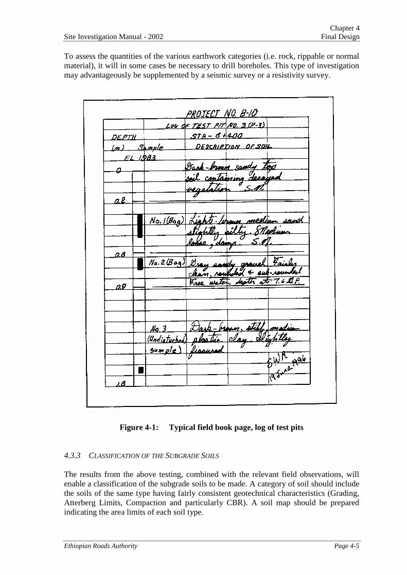
The log of each test pit shall be accurately drawn and included in the Soils and MaterialsReport. A sample test pit log data sheet is shown in Figure 4-1. Photographs should alsobe taken of the test pit location, as well of the soils horizons in the test pit. This will helpboth the engineers in charge of reporting the investigations and in charge of interpretingthe results. Selected, representative photographs should also be included in the Soils andMaterials Report.
4.3.2 RECOMMENDED TESTS ON SOIL SAMPLES
For new road alignments, the following tests shall normally be conducted, as a minimum,on the collected soil samples (see also Appendix B):
1. Grain Size Analysis (AASHTO T88)2. Atterberg Limits (AASHTO T89, T90)3. Moisture Content (AASHTO T265)4. Compaction Test (AASHTO T180)5. CBR and Swell (AASHTO T193)
The compaction test requires preparation of at least four (preferably five) molds forcompaction and at least one mold for CBR. The CBR shall normally be measured afterfour days of soaking, except in arid areas (annual rainfall less than 500 mm). In aridareas, the CBR may be measured at OMC (optimum moisture content) or after a reducedsoaking period, depending on the equilibrium moisture content predicted under thepavement in the area (see ERA Pavement Design Manual - 2002). The compaction testsshall be conducted on samples compacted to 95% of the MDD achieved by AASHTOTest Method T180. The CBR tests shall be conducted at three levels (normally 90%,95%, and 100%) of compaction, and at each level, two conditions of moisture. Thisprocedure is to determine design CBR and to know the effect of the relative compactionand moisture.
Chapter 4Site Investigation Manual - 2002 Final Design
Ethiopian Roads Authority Page 4-5
To assess the quantities of the various earthwork categories (i.e. rock, rippable or normalmaterial), it will in some cases be necessary to drill boreholes. This type of investigationmay advantageously be supplemented by a seismic survey or a resistivity survey.
Figure 4-1: Typical field book page, log of test pits
4.3.3 CLASSIFICATION OF THE SUBGRADE SOILS
The results from the above testing, combined with the relevant field observations, willenable a classification of the subgrade soils to be made. A category of soil should includethe soils of the same type having fairly consistent geotechnical characteristics (Grading,Atterberg Limits, Compaction and particularly CBR). A soil map should be preparedindicating the area limits of each soil type.
Chapter 4Final Design Site Investigation Manual - 2002
Page 4-6 Ethiopian Roads Authority
Usually, the number of soil categories will not exceed 4 or 5 for a given road project. It isadvisable to avoid introducing short sections along the alignment with numerous changesin the soil categories as this can make the construction operations overly complicated.
Additional guidance regarding the soil categories defining a road project may be found inthe ERA Pavement Design Manual - 2002. For pavement design, the road sections mustbe defined in accordance with subgrade strength classes, as follows:
Table 4-3: Subgrade Strength Class vs. CBRs
Subgrade Strength Class Range(CBR %)
S1 2S2 3 – 4S3 5 – 7S4 8 – 14S5 15 – 29S6 30+
Almost all types of soil, ranging from sandy clays through to broken rock, can be usedfor embankment construction and pavement support, the main limitation being the easewith which the material can be handled and compacted. However, materials with CBRsless than 2 are usually very difficult to work and, as subgrade, would lead touneconomical pavement structures. Such soils, except if unavoidable, are usuallyconsidered unsuitable. If they must be used, they must be covered by select subgradematerials or capping layers.
The ERA Pavement Design Manual - 2002 also gives guidance regarding estimatedsubgrade strength classes depending on the plasticity of soils and the depth of the watertable. This estimated correlation can usefully be referred to as a means to ascertain theresults of the above tests.
4.3.4 TREATMENT TESTS (WHEN APPROPRIATE)
If the above compaction and CBR tests show that the available natural materials do notmeet the quantity or quality (as per specifications) requirements for subgrade and/orpavement layers, treatment tests shall be carried out on the relevant large samples.
Treatment may be considered to use the materials, with cement or lime, as roadbasematerials, subbase, or capping or selected fill layers.
The selection of the type of treatment (cement or lime) is based on the plasticity andparticle size distribution of the material to be treated. The laboratory testing procedures toassess the suitability of the materials after cement/lime stabilization are mentioned inAppendix B.
Chapter 4Site Investigation Manual - 2002 Final Design
Ethiopian Roads Authority Page 4-7
4.4 Common Investigations: Existing Roads
This paragraph applies to sections of existing gravel roads that are to be upgraded, thegeometric standards of which are good enough to maintain the existing alignment. Theprocedure and frequency of sampling described herein for new roads applies to theseroads as well.
• Where more than 10 cm of existing gravel wearing course is in place on the road andwhere the shape is adequate, samples of subgrade are to be submitted to laboratorytests (1) to (4) listed above (i.e. identification and compaction test).
• In addition, the Field Moisture Content and Field Dry Density of each sample shall bemeasured; this is to decide whether to leave the subgrade undisturbed or to recompactit. Methods are suggested for the purpose of these measurements in Section 4.1 of thismanual. However, an entire project should not rely entirely on nuclear methods, andverification of the results should be made using in particular the Sand-Cone Method(AASHTO T 191) for in-situ density and AASHTO T 217 for moisture content.
• If the degree of field compaction is found to be consistently satisfactory (preferably atleast 95% of the maximum dry density achieved by AASHTO T180), then CBRsshall be measured in the laboratory at Field Dry Density on representative samples ofthe subgrade. These measurements may be supplemented by direct measurements ofthe subgrade strength using DCP testing (see Appendix C). If the degree ofcompaction is not satisfactory, the subgrade will need recompaction and the CBRsshall then be measured at 95% M.D.D. (AASHTO T180).
• The design moisture content to be adopted in the design of new pavement is to bedetermined based on the project conditions, taking into consideration the depth towater table and rainfall characteristics.
Direct measurements of the subgrade strength may also be taken under existingpavements, as indicated in ERA's Pavement Design Manual - 2002.
4.5 Materials
The Field Investigation Program, in stages, as described in Chapter 3, also applies tomaterials investigation. If the major emphasis of the investigation is on the preliminarystage, the frequency of sampling as intended for the final stage needs to be adopted.
Information gathered during the preliminary stage should enable haulage diagrams to beprepared which show estimated resource volumes and existing minimum haulagedistances. Resource deficiencies will thus be identified.
During the final stage, investigations should be carried out as required at additionalexpected sources to ensure minimum haulage and ample selection of material of suitablequality.
Pavement material searches are generally restricted to a 10 km corridor centering on theroad. The cost of constructing access tracks to pit/quarry sites offset from the road mayvery well be prohibitive to development, so viable sources will require some kind ofexisting track, unless the terrain is very subdued.
Chapter 4Final Design Site Investigation Manual - 2002
Page 4-8 Ethiopian Roads Authority
From the viewpoint of their use in the finished road, materials for road construction (newroad construction or rehabilitation) include:
- Embankment materials: in this chapter, brief considerations are given for the caseswhen common investigations for earthworks and subgrade have revealed conditionsresulting in a need for additional embankment materials (e.g. poor subgradeconditions requiring replacement, or imbalance of quantities or excessive haulagedistances)
- Pavement layers materials: these materials include mainly naturally occurringgranular materials and crushed rock materials
- Rock is also used for concrete, masonry and other miscellaneous uses
- Sand and water also constitute construction materials: sand may be mechanicallymixed with other unbound naturally occurring or crushed materials to improve theircharacteristics, as fine aggregate for bituminous mixes or in cement concrete mix;water is used in earthworks, pavement layers and concrete, as well.
From the viewpoint of the logistics involved in the investigations and testing, however,the materials object of this chapter will be simply classified as:
• Naturally occurring soil and gravel materials
• Crushed stone aggregates (quarry materials)
• Water
Costs relating to the haulage and processing of pavement materials have a considerableimpact upon the economics of the road construction or upgrading. Therefore, during finaldesign, detailed construction material sources and evaluations must be undertaken.
Investigations along road lengths requiring reconstruction should be directed towards thelocation of regularly spaced sources of pavement materials. Emphasis must be givenduring the field studies to the identification of material sources that meet the followingcriteria:
- The material sources must be located as close as possible to the project road.
- The material sources must be located at frequent intervals along the road.
- The material sources should have little overburden and low extraction costs.
- Quarry sites must be located at sites suitable for the erection of crushing plants.
- Blasting should be minimized to produce stone fragments ready for crushing.
- Materials should require minimal processing to achieve a suitable specification.
4.5.1 EXISTING PAVEMENT MATERIALS
Where an existing road is to be upgraded (or rehabilitated) on the same alignment, theexisting pavement materials may provide materials for improved subgrade, subbase orother pavement layers.
Chapter 4Site Investigation Manual - 2002 Final Design
Ethiopian Roads Authority Page 4-9
This may be the case, for instance, for an existing gravel road being upgraded to pavedroad. In such a case, measurements of the thickness and width of the gravel wearingcourse shall be recorded every 100 m. One sample per kilometer of existing gravelwearing course shall be taken where the layer is at least 15 cm thick. Each sample shallbe submitted to tests as per the specifications corresponding to the intended use of thematerial. Normally, the tests to be carried out for gravel material are:
- Sieve analysis- Atterberg limits- Moisture content- Compaction test- CBR test
Other examples of reuse of existing pavement materials include (i) recycling reclaimedasphalt pavement materials and/or reclaimed aggregate materials with new asphalt and(ii) recycling surface materials with new asphalt and aggregate chips for the surfacecourse.
4.5.2 SOIL AND GRAVEL BORROW PITS
Information obtained at the Preliminary Design stage (see Chapter 3) will enable aselection of the most suitable borrow areas to be made. Chapter 3 also summarizes thevarious possible uses of soil and gravel materials as pavement layers materials.Consideration shall be given, during final design, to the following factors:
- Quality of the materials, so as to comply with the specifications for intended use- Location of the proposed borrow areas, so as to minimize haul and obtain the most
economic use of materials- Ease of working (land acquisition, clearance of the site, access, overburden, thickness
of exploitable horizon, etc.)
Natural gravel deposits offering potential for use for road construction may includeoutcrops of closely fractured (rippable) basalt, limestone gravels and possible alluvialdeposits, including riverbeds.
Highly fractured basalt outcrops may represent an easily excavated source of pavementaggregate, but the presence of seams of highly plastic clay may render the materialunsuitable for road base. Also, apparently strong basalt gravels may contain minerals thatare prone to rapid deterioration in service. As a result, closely fractured basalt depositsshould be carefully investigated and tested in a central laboratory to fully establish theirsoundness and engineering characteristics.
Field Investigations and Sampling Procedures
Pits shall be dug at every point on a grid (50 m grid during the preliminary stage and 25m grid during the final stage), through the full depth of the layer(s) proposed for use.
The position of each proposed borrow pit shall be indicated on a key plan. A site plan ofeach proposed borrow pit shall be prepared, showing the position of each test pit, thecharacteristic features of the site and the means of access and location.
Chapter 4Final Design Site Investigation Manual - 2002
Page 4-10 Ethiopian Roads Authority
In every test pit, all layers, including top soil and overburden, shall be accuratelydescribed and their thicknesses measured and recorded. All layers proposed for use shallbe sampled. The log of each test pit shall be accurately drawn and included in the Soilsand Materials Report.
The sample shall be taken over the full depth of the layer proposed for use, by taking avertical slice of material.
The quantity of material in each sample must be sufficient to carry out the testingrequired. The required quantity may be assessed from Table 4-2.
4.5.3 SAMPLES OF SAND
Sand for any type or class of concrete and for mortars requires washed and processedmaterial composed of quartz or other hard durable particles. The sand particles shall bepredominantly angular in shape and be free of soft particles. Also, the material shall benon-plastic in nature.
Sand borrow areas, such as streambed deposits, should be located for use in concrete forbridge and drainage structures. Samples need to be gathered by test pits in representativeareas. Sand may also be used as part of the mix for bituminous mixes, and may also beconsidered as an additive for mechanical stabilization.
4.5.4 EMBANKMENT MATERIALS
In most cases, side borrow will prove sufficient for raising grades in areas notcharacterized by highly plastic soils. Otherwise, borrow areas should be located inadjacent areas with sufficient high caliber borrow materials (e.g., CBR over 5). This mayprove necessary, in particular, in areas of expansive soils. Samples should be gathered bytest pits dug in representative areas.
The tests required on samples of embankment materials have been defined in Chapter 3.
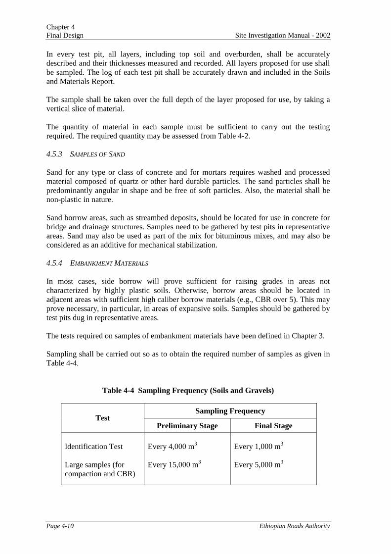
Sampling shall be carried out so as to obtain the required number of samples as given inTable 4-4.
Table 4-4 Sampling Frequency (Soils and Gravels)
Sampling FrequencyTest
Preliminary Stage Final Stage
Identification Test
Large samples (forcompaction and CBR)
Every 4,000 m3
Every 15,000 m3
Every 1,000 m3
Every 5,000 m3
Chapter 4Site Investigation Manual - 2002 Final Design
Ethiopian Roads Authority Page 4-11
Testing
In addition to the testing indicated above, gravel material shall be subjected to some or allof the following tests: (a) Los Angeles Abrasion, (b) Aggregate Crushing Value, and (c)Flakiness Index, depending on its intended use (i.e. as subbase, roadbase, wearingcourse), to verify conformity with the corresponding division of the Specifications.
Tests for Sand
Tests to be undertaken on representative samples of sand include:
- Sieve analysis
- Sand equivalent
- Soundness
The results of the above tests should be compared to the specific project requirements forthe intended use (e.g. concrete, bituminous mix, etc.).
4.5.5 QUARRY MATERIALS
General
Information obtained during the feasibility study will guide in selecting the most suitablequarry sites, on the basis of rock quality, location, access and ease of working.
If possible and if necessary, the quantities of quarry materials may be ascertained bygeophysical methods. Geophysical methods are strongly recommended in particular ifconditions impose a limitation to the number of core borings.
Rock quarries furnish materials for roadbase, gravel surfacing, bituminous surfacing,asphalt wearing surface, and aggregates for concrete. They also furnish large rocks thatcan be used for masonry or scour protection.
Crushed hard rock (basalt and limestone) will often be important sources for roadbasematerials required for new road construction, as well as for upgrading existing roads. Insome cases, it may even prove economical to use crushed materials for subbase. In amajority of cases, it will be more convenient to use crushed aggregates for roadbase,rather than naturally occurring gravels that may contain too many plastic fines.
Each potential source of crushed rock should be examined to determine the rock jointingcharacteristics and weathering profile within the outcrop. Based on the results of the fieldand laboratory investigations, quarry sites with the best excavation characteristics (welljointed) and uniform strength properties should be selected for development. Typically,in many parts of the country, sources of crushed hard rock are available at regularintervals along the alignment.
Investigations, Drilling and Sampling
Each selected potential quarry site shall be investigated as follows:
Chapter 4Final Design Site Investigation Manual - 2002
Page 4-12 Ethiopian Roads Authority
- Test holes shall be dug or drilled on a 30 m grid (average) to prove overburden andascertain quantities.
- Boreholes shall be drilled to prove quantity and quality of rock. It is recommendedthat, normally, the core’s diameter be 76 mm (coring bits required: HWG, formerlyHX). In any case, the minimum coring diameter shall be 55 mm (NWG, formerlyNX), so as to recover stone in sufficient quantity for testing. The log of eachborehole shall be accurately recorded, drawn and included in the Soil and MaterialsReport.
- Consideration should be given to the use of a bulldozer or other mechanicalexcavator to prove the availability of solid rock. Such an excavation may also beshown to bidders during a conducted site visit. This will also allow a better selectionof the locations of borings and facilitate access.
- Samples of fresh rock shall be obtained by hand, or pneumatic drilling from existingfaces and outcrops. Great care shall be taken to avoid sampling from a superficialhorizon of weathered rock and to ensure that the samples are representative of thestone to be used.
- In addition, whenever possible, deeper samples shall be obtained by blasting.
Depending on the consistency of the rock and whether it is an existing or a new quarry, 5to 10 samples are required per quarry during the final stage of the investigation, asagainst 3 samples during the preliminary investigation.
A site plan of each potential quarry shall be prepared, showing the characteristic featuresof the site (outcrops, existing faces, etc.) and the means of access and location.
The position and level of each borehole and each sampling point shall be accuratelydetermined and recorded on the site plan, after the quarries have been drilled.
Each sample shall contain sufficient material to carry out the tests indicated below. Thequantity of material required is on the order of 200 Kg.
Testing
Testing is aimed at verifying the suitability of the rock for the intended use and forconformance with the corresponding division of the Specifications, such as crushed stonesubbase and crushed stone roadbase.
Each sample shall be subjected to the following tests:
1. Los Angeles Abrasion (AASHTO T 96)2. Aggregate Crushing Value (BS 812, Part 110)3. Sodium Sulphate or Magnesium Sulphate Soundness (AASHTO T 104)4. Plasticity Index on fines from the Los Angeles Abrasion test (AASHTO T 89, T 90)
and Plasticity Index on material passing the 425 micron sieve (the latter to verifysuitability of fine aggregate for asphalt concrete mix)
5. Specific Gravity and Absorption of Coarse Aggregate (AASHTO T 84)6. Bitumen Affinity (for stone proposed for use with bitumen, immersion tray test).
Chapter 4Site Investigation Manual - 2002 Final Design
Ethiopian Roads Authority Page 4-13
Moreover, one large sample obtained from each quarry (representative of the stone to beused) shall be crushed with a small crusher (and not broken by hand), to a maximum sizedepending on the proposed use of the stone (usually ranging from 20 to 40 mm). Thecrushed stone shall be submitted to tests (1) through (6) above and, in addition, to thefollowing tests:
(1) Grading to 0.075 mm sieve (AASHTO T 88)(2) Flakiness Index (BS 812, Part 105)(3) Sand Equivalent (AASHTO T 176)
Compaction and CBR tests may also be run for materials intended for use as unboundroadbase materials.
Notes:
1. While the above tests are deemed necessary to ensure the suitability of the materialsfor their purpose (e.g. the preparation of bituminous mixes), it is beyond the scope ofnormal investigations to actually produce specific job-related mixes. Rather, a job-mix formula should be prepared by the Contractor to satisfy the Specifications, e.g. interms of stability. As a result, testing procedures on bituminous mixes are not listedabove. However, references are indicated in Chapter 4.
2. Since the flakiness may be influenced to a significant extent by the crushing process,it may be advisable to repeat the process with some variation (e.g. control of thecrusher feed) to assess the sensitivity of the flakiness index to the process.
4.5.6 WATER
The needs for water during construction must be evaluated, in particular in areas where itis scarce, and additional search is to be planned as required.
Data from a review of topographic maps and the field reconnaissance of the previousstages of study can indicate if sources of surface water for use in construction should be aproblem. Major water sources need to be sampled and analyzed (chloride, sulfate, andorganic content) in order to check their suitability for use in construction of pavementand concrete structures. Consulting hydrogeological maps and literature (e.g. as listed inReferences) may be of use.
Water intended for use in Portland cement concrete shall meet the requirements ofAASHTO T 26.
Tests to be considered for water include:
- Chloride content- Sulphate content- Total dissolved salts- pH
It is usually unlikely the water will contain sufficient salt to prevent their use incompaction of pavement layers or in concrete mixes.
Chapter 4Final Design Site Investigation Manual - 2002
Page 4-14 Ethiopian Roads Authority
4.6 Foundations of Structures
During preliminary design, borings will be required at the anticipated locations of thebridge substructures, although the geometry of the bridge is still subject to change duringfinal design. Soil samples, disturbed and undisturbed as appropriate, should be retrievedfor laboratory testing. The possible foundation solutions should be identified during thepreliminary stage. During the final stage, limited exploration to verify the designassumptions is recommended.
For culverts, a detailed exploration with drilling rigs may not be required. Limitedexploration by way of test pits using hand augers should be sufficient.
4.6.1 SOIL, ROCK AND OTHER PROBLEM CONDITIONS
Geologic and environmental conditions can influence the performance of foundations andmay require special considerations during design. To the extent possible, the presenceand influence of such conditions should be evaluated as part of the subsurfaceexploration program. A representative, but not exclusive, listing of problem conditionsrequiring special consideration is presented below for general guidance.
Soil Problems
- Organic soil; highly plastic clay: low strength and high compressibility- Sensitive clay: potentially large strength loss upon large straining- Micaceous soil: potentially high compressibility- Expansive clay/silt: potentially large expansion upon wetting- Liquefiable soil: complete strength loss and high deformations due to earthquake
loading- Collapsible soil: potentially large deformations upon wetting
Rock Problems
- Laminated rock: low strength when loaded parallel to bedding- Expansive shale: potentially large expansion upon wetting; degrades readily upon
exposure to air/water- Soluble rock: soluble in flowing and standing water (limestone, gypsum)- Cretaceous shale: indicator of potentially corrosive ground water- Weak claystone: low strength and readily degradable upon exposure to air/water- Gneissic and Schistose rock: highly distorted with irregular weathering profiles and
steep discontinuities- Subsidence: typical in areas of underground mining or high ground water extraction- Sinkholes / solutioning: typical of areas underlain by carbonate rock strata (e.g.
limestone, dolomite, etc.)
Condition Problems
- Negative skin friction/expansion loading: additional compressive/uplift load on deepfoundations due to settlement/uplift of soil
- Capillary water: rise of water level in silts and fine sands leading to strength loss
Chapter 4Site Investigation Manual - 2002 Final Design
Ethiopian Roads Authority Page 4-15
4.6.2 SUBSURFACE EXPLORATION AND TESTING PROGRAMS
The elements of the subsurface exploration and testing programs shall be theresponsibility of the designer based on the specific requirements of the project andexperience with local geologic conditions.
General Requirements
As a minimum, the subsurface exploration and testing programs shall define thefollowing, where applicable:
• Soil strata
- Depth, thickness, and variability
- Identification and classification
- Relevant engineering properties (i.e. shear strength, compressibility, stiffness,permeability, expansion or collapse potential)
• Rock strata
- Depth to rock
- Identification and classification
- Quality (i.e. soundness, hardness, jointing and presence of joint filling, resistanceto weathering, if exposed, and solutioning)
- Compressive strength
• Ground water elevation
• Ground surface elevation
• Local conditions requiring special consideration
Exploration logs shall include soil and rock strata descriptions, penetration resistance forsoils (e.g. Standard Penetration Test (SPT) or Cone Penetration Test (CPT)), samplerecovery and RQD (Rock Quality Designation) for rock strata. The drilling equipmentand method, use of drilling mud, type of SPT hammer or cone penetrometer (i.e.mechanical or electrical), and any unusual subsurface conditions such as artesianpressures, boulders or other obstructions, or voids shall also be noted on the explorationlogs. A sample boring log is presented in Appendix B.
Minimum Depth
Where substructure units will be supported on spread footings (in the judgment of theengineer responsible for exploration), the minimum depth of the subsurface explorationshall extend below the anticipated bearing level a minimum of two footing widths (B) forisolated, individual footings where L<= 2 B, and four footing widths for footings whereL>5B (L = footing length). For intermediate footing lengths, the minimum depth ofexploration may be estimated by linear interpolation as a function of L between depths of2 B and 5 B below the bearing level. Greater depths may be required where warranted bylocal conditions.

Chapter 4Final Design Site Investigation Manual - 2002
Page 4-16 Ethiopian Roads Authority
Where substructure units will be supported on deep foundations, the depth of thesubsurface exploration shall extend a minimum of 6 meters below the anticipated pile orshaft tip elevation. Where pile or shaft groups will be used, the subsurface explorationshall extend at least two times the maximum pile group dimension below the anticipatedtip elevation, unless the foundations will be end bearing on or in rock. For piles bearingon rock, a minimum of 3 meters of rock core shall be obtained at each explorationlocation to insure the exploration has not been terminated on a boulder. For shaftssupported on or extending into rock, a minimum of 3 meters of rock core, or a length ofrock core equal to at least three times the shaft diameter for isolated shafts or two timesthe maximum shaft group dimension for a shaft group, whichever is greater, shall beobtained to insure that the exploration has not terminated on a boulder and to determinethe physical characteristics of rock within the zone of foundation influence for the design.
Minimum Coverage
A minimum of two soil borings shall be made for each substructure unit.
Laboratory Testing
Laboratory testing shall be performed as necessary to determine the engineeringproperties of samples, including unit weight, shear strength, compressive strength andcompressibility. In the absence of laboratory testing, engineering properties may beestimated based on published test results or local experience. The designer shall preparethe laboratory testing program. However, Chapters 3 and 4 give general guidelines forselecting the type of test, depending on the nature of the sample.