final copy of new mwd manual
149
Approved By Director Document & Revision No. JIN-DD-MWD-INDUCTION.MANUAL-01 Reviewed By GM Date of issue August 2011 Prepared by Base Coordinator Page 1 of 149 Title MWD/DD-INDUCTION.MANUAL DIRECTIONAL DRILLING INDUCTION MANUAL
-
Upload
anjan-kumar -
Category
Documents
-
view
404 -
download
62
Transcript of final copy of new mwd manual

Approved By Director
Document & Revision No. JIN-DD-MWD-INDUCTION.MANUAL-01
Reviewed By GM
Date of issue August 2011
Prepared by Base Coordinator
Page 1 of 149
Title MWD/DD-INDUCTION.MANUAL
DIRECTIONAL DRILLING
INDUCTION MANUAL

Approved By Director
Document & Revision No. JIN-DD-MWD-INDUCTION.MANUAL-01
Reviewed By GM
Date of issue August 2011
Prepared by Base Coordinator
Page 2 of 149
Title MWD/DD-INDUCTION.MANUAL
DIRECTIONAL DRILLING
INDUCTION MANUAL-01
Issue/Revision : JIN-DD-MWD.IND.MANUAL-01
Compiled By
Kamlesh Unadkat / Vaishali Sali Base Coordinator
Reviewed By
Umesh Thakur / Satish Jawanjal GM (Directional Drilling)
Approved By
Dr. I N Chatterjee Director

Approved By Director
Document & Revision No. JIN-DD-MWD-INDUCTION.MANUAL-01
Reviewed By GM
Date of issue August 2011
Prepared by Base Coordinator
Page 3 of 149
Title MWD/DD-INDUCTION.MANUAL
Table of Contents 1. Introduction to Jindal 7
2. Oil exploration & drilling 10
2.1 Forming oil 10 2.2 Locating Oil 11 2.3 Oil Drilling Preparation 12 2.4 Oil Rig Systems 14 2.5 Testing For Oil 19
3. Directional Drilling 21
3.1 Applications of Directional Drilling 21 3.1.1 Sidetracking 21 3.1.2 Inaccessible Locations 21 3.1.3 Salt Dome Drilling 22 3.1.4 Offshore Multiwell Drilling 23 3.2 Types of Directional Wells 23 3.2.1 “L” profile (Build and Hold) 24 3.2.2 “S” Type Well 24 3.2.3 “J” Type Well 25 3.2.4 Horizontal Well 25 3.3 Geometry of A Directional well 25
4. Drilling of Directional Well 28
4.1 Bottom Hole Assembly 29 4.2 Sizes of BHA Component 30 4.3 Parts of A BHA 30 4.3.1 Drill bit 30 4.3.2 Steerable Downhole Mud Motor 32 4.3.3 Float Sub 36 4.3.4 UBHO (Universal Bore Hole Orienting subs) 37 4.3.5 NMDC (Non Magnetic Drill Collar) 38
4.3.6 Heavy Weight Drill Pipes 38 4.3.7 Drill Collars 39 4.3.8 Stabilizers 39 4.3.9 Crossovers 40

Approved By Director
Document & Revision No. JIN-DD-MWD-INDUCTION.MANUAL-01
Reviewed By GM
Date of issue August 2011
Prepared by Base Coordinator
Page 4 of 149
Title MWD/DD-INDUCTION.MANUAL
5. Measurement 42
5.1 Inclination/ Azimuth/ Measured Depth 42 5.2 True North and Magnetic North 43 5.3 Earth’s Magnetic Field 44 5.4 Earth’s Magnetic Components 44
6. MWD 46
6.1 Introduction 46 6.2 What Is MWD? 46 6.3 Mud Pulse Telemetry 46 6.4 MWD Principles 48
6.4.1 Positive Mud Pulse Telemetry 48 6.4.2 Negative Mud Pulse Telemetry 48 6.4.3 Continuous Wave Telemetry 48 6.4.4 Electromagnetic Telemetry 48
6.5 MWD TOOL Components 51
6.5.1 Dummy Switch 51 6.5.2 Centralizer 51 6.5.3 Electronics Module 52 6.5.4 Gamma Tool 53 6.5.5 Battery 55 6.5.6 Pulsar Driver System 56 6.5.7 Stringer Assembly 57
6.6 MWD STRING 58 6.6.1 Gamma Job 58 6.6.2 Non-Gamma Job 58
6.7 Placing MWD tool in the BHA 60 6.8 KINTEC PIN CONNECTIONS 62 6.9 Working of MWD tool 62 6.10 MWD Tool Retrieval Equipment 64 6.11 TOOLFACE 65 6.12 Fluidic Vortex 66 6.13 Azimuth Correction Technique 67 6.14 Basic Hydraulics 69
6.14.1 System Pressure 69 6.14.2 Annular Velocity 70

Approved By Director
Document & Revision No. JIN-DD-MWD-INDUCTION.MANUAL-01
Reviewed By GM
Date of issue August 2011
Prepared by Base Coordinator
Page 5 of 149
Title MWD/DD-INDUCTION.MANUAL
6.14.3 Pressure Pulses 71 6.14.4 Drilling Fluid 71
6.15 Factors Affecting the Mud Pulse 72 6.16 Reliability 72
7. Tensor MWD Battery Manual 74 7.1 Procedure for Leaking or Vented Batteries 76 7.2 Procedure for Hot Batteries 77 7.3 Procedure for Exploding Batteries 77 7.4 Procedure for Lithium Fire 78 7.5 Lithium Battery Safety 78 7.6 Storage and Disposal Tips 80 7.7 Handling and Inspection Guidelines 81 7.8 Handling during Product Assembly 82
8. QMWD-SAP System 84
8.1 System Description 84 8.2 Toolface Offset Procedures 87 8.3 Summary of the Features Of Qmwd V 01.30 90 8.4 Summary of Features of Qmwdpc V 01.20 92 8.5 Summary of New Features in Qmwd V02.02 95
9. TRU-VU User Guide 97
9.1 Tru Vu Data Wise System Setup 97 9.2 Printing Plots 103 9.3 Calibration 112 9.4 Miscellaneous Notes 114 9.5 Tru-Vu Renewal Procedure 115
10. Drill Well User Guide 117
10.1 Configuration 117 10.2 Loading Parameters From A Device 120 10.3 Xxtalk Utility 120 10.4 Drillwell Main Screen 122 10.5 Tools Screen 125 10.6 Depth Tracking Setup 126 10.7 TFO Procedure 126 10.8 Wits Setup 128

Approved By Director
Document & Revision No. JIN-DD-MWD-INDUCTION.MANUAL-01
Reviewed By GM
Date of issue August 2011
Prepared by Base Coordinator
Page 6 of 149
Title MWD/DD-INDUCTION.MANUAL
11. Ring Out Test Sheet 145
12. Poppet Orifice Chart 147

Approved By Director
Document & Revision No. JIN-DD-MWD-INDUCTION.MANUAL-01
Reviewed By GM
Date of issue August 2011
Prepared by Base Coordinator
Page 7 of 149
Title MWD/DD-INDUCTION.MANUAL
1. INTRODUCTION
This is the official “Jindal Drilling MWD Training Guide.” This manual is designed
to help novice and seasoned oilfield worker make the transition into becoming an
MWD Engineer specializing in the use of probe based positive pulse telemetry
MWD system.
This manual is intended to be used with your in-field training to give you the best
possible chance for success.
The only dumb question is the one you didn’t ask and should have. By not asking
a question you may inadvertently miss an important point that could cause
trouble in field and cost thousands of dollars.
Guide to Safety
You must take adequate precautions before you start working on any operations.
A health and safety introduction will be conducted before you can go to any rig
sites.
You’ll be shown current handling and cleaning methods for all equipment that
your job requires you to use.
Ensure your equipment is in good working order to prevent accidents from
happening.

Approved By Director
Document & Revision No. JIN-DD-MWD-INDUCTION.MANUAL-01
Reviewed By GM
Date of issue August 2011
Prepared by Base Coordinator
Page 8 of 149
Title MWD/DD-INDUCTION.MANUAL
In case of an accident, report it to management immediately.
PERSONAL PROTECTIVE EQUIPMENT When working on an oil rig, appropriate attire, coverall is required. Any
clothing underneath the coverall should be fire retardant or at very least
breathable and slow burning.
The uniform should be clean and in good repair when you go to a job site. You should look professional when at any jobsite.
For safety reasons your hair must be cut short. If you have longer hair it must be
tied back or put in a pony tail and you should come clean shaven for work.
MWD uniforms consist of:
Fire retardant coveralls
CSA approved Hard hat
CSA approved steel toed Boots
Hearing protection
Gloves
TAKE PRIDE IN YOUR WORK AND WHERE YOU WORK! You are responsible for maintaining your equipment.

Approved By Director
Document & Revision No. JIN-DD-MWD-INDUCTION.MANUAL-01
Reviewed By GM
Date of issue August 2011
Prepared by Base Coordinator
Page 9 of 149
Title MWD/DD-INDUCTION.MANUAL
Ensure all tools and equipment is clean and in good working order, ensure your
toolboxes have adequate supplies to complete a job professionally – all the time.
Please keep any living/work area clean for yourselves and your co-workers.
Ensure you clean up any shacks properly before leaving a job site.
Work Smart – Work Safe MWD ENGINEER RESPONSIBILITIES
The MWD Engineer must know how a rig operates as the rig operations
affect the working of the MWD tool. In this knowing the BHA( bottom hole
assembly) in hole is a must.
An MWD Engineer must know how the different components of an MWD
string operate and how they contribute to drilling.
An MWD Engineer must reduce the problems and downtime.
An MWD Engineer must always remember that they are representing their
company in front of the client hence proper behavior is expected of the
operator always in their shift.

Approved By Director
Document & Revision No. JIN-DD-MWD-INDUCTION.MANUAL-01
Reviewed By GM
Date of issue August 2011
Prepared by Base Coordinator
Page 10 of 149
Title MWD/DD-INDUCTION.MANUAL
2. Oil exploration & Drilling 2.1 Forming oil Oil comes from organic matter that died and sank into the sand at the bottom of
the sea.
Over the years, the organisms decayed in the sedimentary layers. In these
layers, there was little or no oxygen present so microorganisms broke the
remains into carbon-rich compounds that formed organic layers which formed
the source rock. As new sedimentary layers were deposited, they exerted intense
pressure and heat on the source rock. The heat and pressure distilled the
organic material into crude oil and natural gas. The oil flowed from the source
rock and accumulated in thicker, more porous limestone or sandstone,
called reservoir rock. Oil and natural gas in the reservoir rocks got trapped
between layers of impermeable rock, or cap rock.
The different types of trap systems are:
Structural traps
Folds - Horizontal movements press inward and move the rock layers upward
into a fold.
Faults - The layers of rock crack, and one side shifts upward or downward.

Approved By Director
Document & Revision No. JIN-DD-MWD-INDUCTION.MANUAL-01
Reviewed By GM
Date of issue August 2011
Prepared by Base Coordinator
Page 11 of 149
Title MWD/DD-INDUCTION.MANUAL
Stratigraphic traps Pinch out - A layer of impermeable rock is squeezed upward into the reservoir
rock.
2.2 Locating Oil
Searching for oil over water using seismology
Whether employed directly by an oil company or under contract from a private
firm, geologists are the ones responsible for finding oil. Their task is to find the
right conditions for an oil trap -- the right source rock, reservoir rock and
entrapment. Modern oil geologists also examine surface rocks and terrain, with
the additional help of satellite images. However, they also use a variety of other

Approved By Director
Document & Revision No. JIN-DD-MWD-INDUCTION.MANUAL-01
Reviewed By GM
Date of issue August 2011
Prepared by Base Coordinator
Page 12 of 149
Title MWD/DD-INDUCTION.MANUAL
methods to find oil. They can use sensitive gravity meters to measure tiny
changes in the Earth's gravitational field that could indicate flowing oil, as well as
sensitive magnetometers to measure tiny changes in the Earth's magnetic field
caused by flowing oil. They can detect the smell of hydrocarbons using sensitive
electronic noses called sniffers. Finally, and most commonly, they
use seismology, creating shock waves that pass through hidden rock layers and
interpreting the waves that are reflected back to the surface.
In seismic surveys, a shock wave is created by the following:
Compressed-air gun - shoots pulses of air into the water (for exploration
over water)
Thumper truck - slams heavy plates into the ground (for exploration over
land)
Explosives - detonated after being drilled into the ground (for exploration
over land) or thrown overboard (for exploration over water)
The shock waves travel beneath the surface of the Earth and are reflected back
by the various rock layers. The reflections travel at different speeds depending
upon the type or density of rock layers through which they must pass. Sensitive
microphones or vibration detectors detect the reflections of the shock waves --
hydrophones over water, seismometers over land. Seismologists interpret the
readings for signs of oil and gas traps.
Once geologists find a prospective oil strike, they mark the location
using GPS coordinates on land or by marker buoys on water.

Approved By Director
Document & Revision No. JIN-DD-MWD-INDUCTION.MANUAL-01
Reviewed By GM
Date of issue August 2011
Prepared by Base Coordinator
Page 13 of 149
Title MWD/DD-INDUCTION.MANUAL
2.3 Oil Drilling Preparation
Once the site has been selected, scientists survey the area to determine its
boundaries, and conduct environmental impact studies if necessary. The oil
company may need lease agreements, titles and right-of way accesses before
drilling the land. For off-shore sites, legal jurisdiction must be determined.After
the legal issues are settled, the crew goes about preparing the land:
1. The land must be cleared and leveled, and access roads may be built.
2. Because water is used in drilling, there must be a source of water nearby.
If there is no natural source, the crew drills a water well.
3. The crew digs a reserve pit, which is used to dispose of rock cuttings and
drilling mud during the drilling process, and lines it with plastic to protect
the environment. If the site is an ecologically sensitive area, such as a
marsh or wilderness, then the cuttings and mud must be disposed of
offsite -- trucked away instead of placed in a pit.
Once the land has been prepared, the crew digs several holes to make way for
the rig and the main hole. A rectangular pit called a cellar is dug around the
location of the actual drilling hole. The cellar provides a work space around the
hole for the workers and drilling accessories. The crew then begins drilling the
main hole, often with a small drill truck rather than the main rig. The first part of
the hole is larger and shallower than the main portion, and is lined with a large-
diameter conductor pipe. The crew digs additional holes off to the side to
temporarily store equipment -- when these holes are finished, the rig equipment
can be brought in and set up.

Approved By Director
Document & Revision No. JIN-DD-MWD-INDUCTION.MANUAL-01
Reviewed By GM
Date of issue August 2011
Prepared by Base Coordinator
Page 14 of 149
Title MWD/DD-INDUCTION.MANUAL
Depending upon the remoteness of the drill site and its access, it may be
necessary to bring in equipment by truck, helicopter or barge. Some rigs are built
on ships or barges for work on inland water where there is no foundation to
support a rig (as in marshes or lakes).
In the next section, we'll look at the major systems of an oil rig.
2.4 Oil Rig Systems
PARTS OF A RIG
No diagram can ever explain a drilling rig completely unless you don’t see
one for yourself but in trying to familiarize you with the different parts here is a rig
schematic.
Parts of the rig are shown in the next page.

Approved By Director
Document & Revision No. JIN-DD-MWD-INDUCTION.MANUAL-01
Reviewed By GM
Date of issue August 2011
Prepared by Base Coordinator
Page 15 of 149
Title MWD/DD-INDUCTION.MANUAL
One can divide the rig into three major sections:
a) Power system
Large diesel engines - burn diesel-fuel oil to provide the main source of
power
Electrical generators - powered by the diesel engines to provide
electrical power b) Mechanical system - driven by electric motors

Approved By Director
Document & Revision No. JIN-DD-MWD-INDUCTION.MANUAL-01
Reviewed By GM
Date of issue August 2011
Prepared by Base Coordinator
Page 16 of 149
Title MWD/DD-INDUCTION.MANUAL
Hoisting system - used for lifting heavy loads; consists of a mechanical
winch (draw works) with a large steel cable spool, a block-and-tackle
pulley and a receiving storage reel for the cable.
Turntable - part of the drilling apparatus
c) Rotating equipment - used for rotary drilling
Swivel - large handle that holds the weight of the drill string; allows the
string to rotate and makes a pressure-tight seal on the hole
Kelly - four- or six-sided pipe that transfers rotary motion to the turntable
and drill string
Turntable or rotary table - drives the rotating motion using power from
electric motors
Drill string - consists of drill pipe (connected sections of about 30 feet (10
meters) and drill collars (DC) and heavy weight drill pipes (HWDP)
(larger diameter, heavier pipe that fits around the drill pipe and places
weight on the drill bit which helps in drilling)
Drill bit - end of the drill that actually cuts up the rock; comes in many
shapes and materials (tungsten carbide steel, diamond) that are
specialized for various drilling tasks and rock formations.
A few other parts are:
Derrick - support structure that holds the drilling apparatus; tall enough to
allow new sections of drill pipe to be added to the drilling apparatus as
drilling progresses

Approved By Director
Document & Revision No. JIN-DD-MWD-INDUCTION.MANUAL-01
Reviewed By GM
Date of issue August 2011
Prepared by Base Coordinator
Page 17 of 149
Title MWD/DD-INDUCTION.MANUAL
CIRCULATORY SYSTEM
The mud pump is like the heart of the rig whereas the mud is like the blood that
flow through the system. Pumps drilling mud (mixture of water, clay, weighting
material and chemicals, used to lift rock cuttings from the drill bit to the surface)
under pressure through the kelly, rotary table, drill pipes and drill collars A
diagrammatic representation of the circulatory system is:

Approved By Director
Document & Revision No. JIN-DD-MWD-INDUCTION.MANUAL-01
Reviewed By GM
Date of issue August 2011
Prepared by Base Coordinator
Page 18 of 149
Title MWD/DD-INDUCTION.MANUAL
Pump - sucks mud from the mud pits and pumps it to the drilling
apparatus
Pipes and hoses - connects pump to drilling apparatus
Mud-return line - returns mud from the hole
Shale shaker - shaker/sieve that separates rock cuttings from
the mud
Shale slide - conveys cuttings to the reserve pit
Reserve pit - collects rock cuttings separated from the mud
Mud pits - where drilling mud is mixed and recycled
Mud-mixing hopper - where new mud is mixed and then sent
to the mud pits
Blowout preventer - high-pressure valves (located under the land rig or on
the sea floor) that seal the high-pressure drill lines and relieve pressure when
necessary to prevent a blowout (uncontrolled gush of gas or oil to the surface,
often associated with
fire).
Approved By Director
Document & Revision No. JIN-DD-MWD-INDUCTION.MANUAL-01
Reviewed By GM
Date of issue August 2011
Prepared by Base Coordinator
Page 19 of 149
Title MWD/DD-INDUCTION.MANUAL
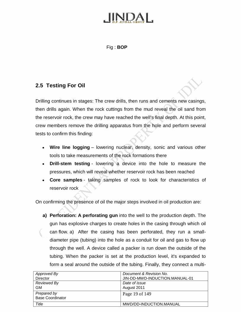
Fig : BOP
2.5 Testing For Oil
Drilling continues in stages: The crew drills, then runs and cements new casings,
then drills again. When the rock cuttings from the mud reveal the oil sand from
the reservoir rock, the crew may have reached the well's final depth. At this point,
crew members remove the drilling apparatus from the hole and perform several
tests to confirm this finding:
Wire line logging – lowering nuclear, density, sonic and various other
tools to take measurements of the rock formations there
Drill-stem testing - lowering a device into the hole to measure the
pressures, which will reveal whether reservoir rock has been reached
Core samples - taking samples of rock to look for characteristics of
reservoir rock
On confirming the presence of oil the major steps involved in oil production are:
a) Perforation: A perforating gun into the well to the production depth. The
gun has explosive charges to create holes in the casing through which oil
can flow. a) After the casing has been perforated, they run a small-
diameter pipe (tubing) into the hole as a conduit for oil and gas to flow up
through the well. A device called a packer is run down the outside of the
tubing. When the packer is set at the production level, it's expanded to
form a seal around the outside of the tubing. Finally, they connect a multi-

Approved By Director
Document & Revision No. JIN-DD-MWD-INDUCTION.MANUAL-01
Reviewed By GM
Date of issue August 2011
Prepared by Base Coordinator
Page 20 of 149
Title MWD/DD-INDUCTION.MANUAL
valve structure called a Christmas tree to the top of the tubing and cement
it to the top of the casing. The Christmas tree allows them to control the
flow of oil from the well. After the well is completed, the crew must start
the flow of oil into the well. For limestone reservoir rock, acid is pumped
down the well and out the perforations. The acid dissolves channels in the
limestone that lead oil into the well.
For sandstone reservoir rock, a specially blended fluid
containing proppants (sand, walnut shells, aluminum pellets) is pumped down
the well and out the perforations. The pressure from this fluid makes small
fractures in the sandstone that allow oil to flow into the well, while the proppants
hold these fractures open. Once the oil is flowing, the oil rig is removed from the
site and production equipment is set up to extract the oil from the well.

Approved By Director
Document & Revision No. JIN-DD-MWD-INDUCTION.MANUAL-01
Reviewed By GM
Date of issue August 2011
Prepared by Base Coordinator
Page 21 of 149
Title MWD/DD-INDUCTION.MANUAL
3. Directional Drilling
Directional drilling is a subsection of drilling which involves deviating a well bore
along a planned course to a subsurface target whose location is a given lateral
distance and direction from the vertical.
3.1 Applications of Directional Drilling 3.1.1 Sidetracking: Side-tracking was the original directional drilling technique.
Initially, sidetracks were “blind”. The objective was simply to get past a fish in
vertical hole. Oriented sidetracks are performed to hit a specific target. It may be
necessary due to an unsuccessful fishing job in a deviated well. Oriented
sidetracks are most widely used. They are performed when, for example, there
are unexpected changes in geological configuration (Figure 1-1).
Figure 1-1 Side tracking

Approved By Director
Document & Revision No. JIN-DD-MWD-INDUCTION.MANUAL-01
Reviewed By GM
Date of issue August 2011
Prepared by Base Coordinator
Page 22 of 149
Title MWD/DD-INDUCTION.MANUAL
3.1.2 Inaccessible Locations: Targets located beneath a city, a river or in
environmentally sensitive areas make it necessary to locate the drilling rig some
distance away. A directional well is drilled to reach the target (Figure 1-2).
Figure 1-2 Inaccessible locations
3.1.3 Salt Dome Drilling: Salt domes have been found to be natural traps of oil
accumulating in strata beneath the overhanging hard cap. There are severe
drilling problems associated with drilling a well through salt formations. These
can be somewhat alleviated by using a salt-saturated mud. Another solution is to
drill a directional well to reach the reservoir (Figure 1-3), thus avoiding the
problem of drilling through the salt.

Approved By Director
Document & Revision No. JIN-DD-MWD-INDUCTION.MANUAL-01
Reviewed By GM
Date of issue August 2011
Prepared by Base Coordinator
Page 23 of 149
Title MWD/DD-INDUCTION.MANUAL
Figure 1-3 Salt dome drilling
3.1.4 Offshore Multiwell Drilling: Directional drilling from a multiwell offshore
platform is the most economic way to develop offshore oil fields (Figure 1-4).
Onshore, a similar method is used where there are space restrictions e.g. jungle,
swamp. Here, the rig is skidded on a pad and the wells are drilled in “clusters".
Figure 1-4 Offshore multiwell drilling

Approved By Director
Document & Revision No. JIN-DD-MWD-INDUCTION.MANUAL-01
Reviewed By GM
Date of issue August 2011
Prepared by Base Coordinator
Page 24 of 149
Title MWD/DD-INDUCTION.MANUAL
3.2 Types of Directional Wells
A carefully conceived directional drilling program based on geological
information, knowledge of mud and casing program, target area etc., is used to
select a hole pattern suitable for the operation. However, experience has shown
that most deflected holes will fit one of the following types.
Directional Patterns
L profile well (Build And Hold)
S profile well (Build and Drop)
J profile well (Deep Kick-Off and Build)
Horizontal well (can be a sub category of J profile well)
– Single
– Extended reach drilling (ERD)
– Multilateral
3.2.1 “L” profile (Build and Hold)
The well is drilled at shallow depth and the inclination is locked in until the target
zone is penetrated.
Fig. “L” profile well Fig. “S” profile well

Approved By Director
Document & Revision No. JIN-DD-MWD-INDUCTION.MANUAL-01
Reviewed By GM
Date of issue August 2011
Prepared by Base Coordinator
Page 25 of 149
Title MWD/DD-INDUCTION.MANUAL
3.2.2 “S” Type Well
The well is deflected at a shallow depth until the maximum required inclination is
achieved. The well path is then locked in and, finally, the inclination is reduced to
a lower value or, in some cases, the well is returned back to vertical by gradually
dropping off the angle.
3.2.3 “J” Type Well
The well is deflected at a much deeper position and after achieving the desired
inclination the well is locked in until the target zone is penetrated.
Fig: “J” type well Fig: Horizontal well

Approved By Director
Document & Revision No. JIN-DD-MWD-INDUCTION.MANUAL-01
Reviewed By GM
Date of issue August 2011
Prepared by Base Coordinator
Page 26 of 149
Title MWD/DD-INDUCTION.MANUAL
3.2.4 Horizontal Well
The well is deflected at a deeper depth and the angle of inclination achieved is
90 degree.
3.3 Geometry of a Directional Well A directional well is drilled from the surface to reach a target area along the
shortest possible path. Owing to changing rock properties, the hole path rarely
follows a single plane but, instead, changes its inclination and direction
continuously. Thus, the deviated well should be viewed in three dimensions, such
that hole inclination and hole direction are specified at each position. Terms that
are commonly used in directional drilling are defined below.

Approved By Director
Document & Revision No. JIN-DD-MWD-INDUCTION.MANUAL-01
Reviewed By GM
Date of issue August 2011
Prepared by Base Coordinator
Page 27 of 149
Title MWD/DD-INDUCTION.MANUAL
Fig: S profile showing different parts.
A simple build/hold/drop well profile, known as an "S" well, is shown in Figure
above.
The kickoff point (KOP) is the beginning of the build section. A build section is
frequently designed at a constant buildup rate (BUR) until the desired hole angle
or end-of-build (EOB) target location is achieved.
Hole angle, or inclination, is always expressed in terms of the angle of the
wellbore from vertical.
The direction or azimuth of the well is expressed with respect to some reference
plane, usually true north. The location of a point in the well is generally
Approved By Director
Document & Revision No. JIN-DD-MWD-INDUCTION.MANUAL-01
Reviewed By GM
Date of issue August 2011
Prepared by Base Coordinator
Page 28 of 149
Title MWD/DD-INDUCTION.MANUAL
expressed in Cartesian coordinates with the wellhead or the rig's rotary kelly
bushing (RKB) usually as the reference location.
True vertical depth (TVD) is expressed as the vertical distance below RKB.
Measured depth (MD) The distance measured along the actual course of the bore
hole from the surface reference point to the survey point.
Departure / drift is the distance between two survey points as projected onto the
horizontal plane.
The EOB specification also contains another important requirement, which is the
angle and direction of the well at that point. The correct angle and direction are
critical in allowing the next target to be achieved; also, it may be necessary to
penetrate the pay zone at some optimum angle for production purposes.
A tangent/hold section is shown after the build section. The purpose of the
tangent is to maintain angle and direction until the next target is reached.
In the example well, a drop section is shown at the end of the tangent. The
purpose of a drop is usually to place the wellbore in the reservoir in the optimum
orientation with respect to formation permeability or in-situ formation stress;
alternatively, a horizontal extension may be the preferred orientation in the case
of a pay zone that contains multiple vertical fractures or that has potential for gas
or water coning.

Approved By Director
Document & Revision No. JIN-DD-MWD-INDUCTION.MANUAL-01
Reviewed By GM
Date of issue August 2011
Prepared by Base Coordinator
Page 29 of 149
Title MWD/DD-INDUCTION.MANUAL
4. DRILLING OF DIRECTIONAL WELL
Directional wells are drilled with specialized equipments which are placed in the
Bottom Hole Assembly. There are many specialized equipments which are used
to drill directional wells. Some of the combinations of the specialized directional
equipments are:
1. Steerable Downhole Mud Motor (SDMM) & Measurement While Drilling
(MWD).
2. Whipstock & MWD.
3. Jetting & MWD.
In all these combinations the former refers to directional equipment which
actually deviates the well from the vertical. The latter refers to a measurement
system which detects the change in orientation of the well caused due to the
former. Earlier a magnetic single shot or multiple shot was used to determine the
direction and orientation of the well. However a MWD system has completely
replaced the magnetic single or multiple shot as it gives readings in real time.
Largely, a combination of SDMM and MWD system is used in the drilling
industry.
Approved By Director
Document & Revision No. JIN-DD-MWD-INDUCTION.MANUAL-01
Reviewed By GM
Date of issue August 2011
Prepared by Base Coordinator
Page 30 of 149
Title MWD/DD-INDUCTION.MANUAL
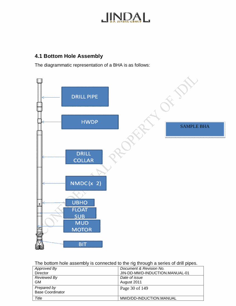
4.1 Bottom Hole Assembly The diagrammatic representation of a BHA is as follows:
The bottom hole assembly is connected to the rig through a series of drill pipes.
SAMPLE BHA

Approved By Director
Document & Revision No. JIN-DD-MWD-INDUCTION.MANUAL-01
Reviewed By GM
Date of issue August 2011
Prepared by Base Coordinator
Page 31 of 149
Title MWD/DD-INDUCTION.MANUAL
4.2 SIZES OF BHA COMPONENT
Sizes of BHA components for different hole section
Hole section
CASING SIZE SDMM TUBULARS MULESHOE
THREAD CONNECTIONS
26” 20” 9 5/8” 8” 5” 7 5/8” R 7 5/8” R 17 ½ “ 13 3/8“ 9 5/8” 8” 5” 6 5/8” R 7 5/8” R 12 ¼” 9 5/8”” 8” 8” 5” 6 5/8” R 6 5/8” R 8 ½” 7” 6 ¾” 6 ¾” 3 ½” 4 ½” R 4” IF 6“ 5” 4 ¾” 4 ¾” 2 7/8” 3 ½” R 3 ½” IF
All sizes in inches
4.3 PARTS OF A BHA
4.3.1 Drill bit
The drilling bit will perform the cutting of the formation. There are different types
of drill bits which are suitable for different formations and downhole applications.
Every bit has an IADC (International Association of Drilling Contractors)
Approved By Director
Document & Revision No. JIN-DD-MWD-INDUCTION.MANUAL-01
Reviewed By GM
Date of issue August 2011
Prepared by Base Coordinator
Page 32 of 149
Title MWD/DD-INDUCTION.MANUAL
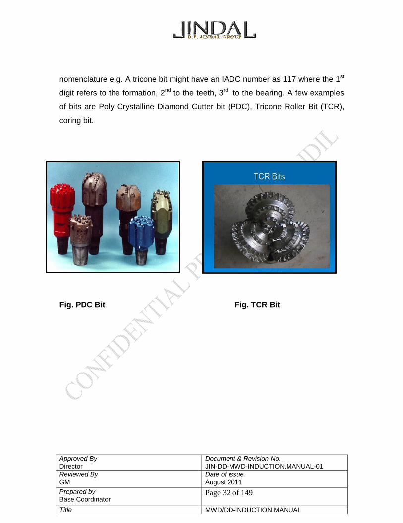
nomenclature e.g. A tricone bit might have an IADC number as 117 where the 1st
digit refers to the formation, 2nd to the teeth, 3rd to the bearing. A few examples
of bits are Poly Crystalline Diamond Cutter bit (PDC), Tricone Roller Bit (TCR),
coring bit.
Fig. PDC Bit Fig. TCR Bit

Approved By Director
Document & Revision No. JIN-DD-MWD-INDUCTION.MANUAL-01
Reviewed By GM
Date of issue August 2011
Prepared by Base Coordinator
Page 33 of 149
Title MWD/DD-INDUCTION.MANUAL
4.3.2 Steerable Downhole Mud Motor
Fig. Steerable Down Hole Mud Motor

Approved By Director
Document & Revision No. JIN-DD-MWD-INDUCTION.MANUAL-01
Reviewed By GM
Date of issue August 2011
Prepared by Base Coordinator
Page 34 of 149
Title MWD/DD-INDUCTION.MANUAL
Steerable Downhole Mud Motor
The above figure shows a steerable downhole mud motor connected to a bit.
Motor Selection
• These are the three common motor configurations which provide a broad range
of bit speeds and torque outputs required satisfying a multitude of drilling
applications.
• High Speed / Low Torque - 1:2 Lobe
• Medium Speed / Medium Torque – 4:5 Lobe
• Low Speed / High Torque – 7:8 Lobe
High Speed / Low Torque (1:2) motor typically used when:
• Drilling with diamond bits.
• Drilling with tri-cone bits in soft formations.
• Directional drilling using single shot orientations.
• Medium Speed / Medium Torque (4:5) motor typically used for: • Conventional and directional drilling
• Diamond bit and coring applications
• Sidetracking wells
Low Speed / High Torque (7:8) motor typically used for:
• Most directional and horizontal wells.
• Medium to hard formation drilling.
• PDC bit drilling applications
Components of PDM Motors
• Dump Sub Assembly
• Power Section

Approved By Director
Document & Revision No. JIN-DD-MWD-INDUCTION.MANUAL-01
Reviewed By GM
Date of issue August 2011
Prepared by Base Coordinator
Page 35 of 149
Title MWD/DD-INDUCTION.MANUAL
• Drive Assembly
• Adjustable Assembly
• Sealed Bearing Section
Dump Sub Assembly
• Hydraulically actuated valve located at the top of the drilling motor
• Allows the drill string to fill when running in hole.
• Drain when tripping out of hole
• When the pumps are engaged, the valve automatically closes and directs
all drilling fluid flow through the motor.
Power Section
• Converts hydraulic power from the drilling fluid into mechanical power to drive
the bit
• Stator – steel tube containing a bonded elastomer insert with a lobed, helical
pattern bore through the center.
• Rotor – lobed, helical steel rod
• When drilling fluid is forced through the power section, the pressure drop across
the cavities will cause the rotor to turn inside the stator.
• Pattern of the lobes and the length of the helix dictate the output characteristics
• Stator always has one more lobe than the rotor.
• Stage – one full helical rotation of the lobed stator.
Dump Sub • Allows Drill String Filling and Draining
• Operation
- Pump Off - Open
- Pump On - Closed
• Discharge Plugs
• Connections

Approved By Director
Document & Revision No. JIN-DD-MWD-INDUCTION.MANUAL-01
Reviewed By GM
Date of issue August 2011
Prepared by Base Coordinator
Page 36 of 149
Title MWD/DD-INDUCTION.MANUAL
• With more stages, the power section is capable of greater differential pressure,
which in turn provides more torque to the rotor.
The stator elastomer can be made of different materials, such as NBR, HNBR,
EPDM etc. The elastomer is chosen considering the type of operation involved.
For higher temperature and pressure conditions, where oil based mud is used;
better elastomers such as HNBR is used.
Drive Assembly
• Converts Eccentric Rotor Rotation into Concentric Rotation– Universal Joint
Adjustable Assembly
• Can be set from zero to three degrees
• Field adjustable in varying increments to the maximum bend angle
• Provides a wide range of potential build rates in directional and horizontal wells
Sealed Bearing Section
Drive Assembly Sealed Bearing
Section

Approved By Director
Document & Revision No. JIN-DD-MWD-INDUCTION.MANUAL-01
Reviewed By GM
Date of issue August 2011
Prepared by Base Coordinator
Page 37 of 149
Title MWD/DD-INDUCTION.MANUAL
• Transmits axial and radial loads from the bit to the drillstring
• Thrust Bearing • Radial Bearing
• Oil Reservoir • Balanced Piston
• High Pressure Seal •Bit Box Connection
Operation modes
Rotating mode- In this mode the entire drill string is rotated with the help of rotary
table. The drill bit is rotating due to the combined action of mud motor and the
rotary table speed.
Sliding mode- In this mode the entire drill string is not rotated. The drill bit is only
rotating due to the mud motor. The bend of the mud motor is made to face in a
specified direction or angle. Drilling carried out in this way is called sliding.
4.3.3 Float Sub
Fig. Float sub and float valve

Approved By Director
Document & Revision No. JIN-DD-MWD-INDUCTION.MANUAL-01
Reviewed By GM
Date of issue August 2011
Prepared by Base Coordinator
Page 38 of 149
Title MWD/DD-INDUCTION.MANUAL
Float sub houses the float valve which acts as a non return valve and
prevents the backflow of mud into our tool during a sudden pressure shoot
up.
4.3.4 UBHO (Universal Bore Hole Orienting subs)
Fig. UBHO
UBHO’s are also called mule shoe subs as they house the mule shoe.
The muleshoe is inserted for the alignment of the MWD string. At the
bottom of the MWD tool is a cut with mates with the landing key in the
muleshoe. The key helps in orienting the MWD string with the bent in the
mud motor.

Approved By Director
Document & Revision No. JIN-DD-MWD-INDUCTION.MANUAL-01
Reviewed By GM
Date of issue August 2011
Prepared by Base Coordinator
Page 39 of 149
Title MWD/DD-INDUCTION.MANUAL
4.3.5 NMDC (Non Magnetic Drill Collar)
Fig. NMDC
NMDCs house the MWD tool. Usually 2 non magnetic drill collars are used
in the BHA in order to reduce the magnetic interference between the
earths magnetic field and the magnetic field from the other magnetic
components in the drill.string. NMDC’s are made up of stainless steel.
4.3.6 Heavy Weight Drill Pipes
Fig. A stand of HWDP comprising 3 HWDPs
As the name suggests the HWDP’s are heavier than normal drill pipes and
impart weight to the BHA. But we must be careful as to how many weights
are used as the weight given to the bit will be difficult to control

Approved By Director
Document & Revision No. JIN-DD-MWD-INDUCTION.MANUAL-01
Reviewed By GM
Date of issue August 2011
Prepared by Base Coordinator
Page 40 of 149
Title MWD/DD-INDUCTION.MANUAL
4.3.7 Drill Collars
Drill Collars also contribute weight to the BHA which in turn provides the
pressure to the bit required for drilling. Drill collars are larger than normal
drill pipes.
There are a few more important components in the BHA that have not been
shown in the schematic diagram
4.3.8 Stabilizers
Stabilizers provide stiffness to the BHA and they are of the same size of
the hole being drilled or 1/8”, ¼”, ½” underguaged. The placement of
stabilizers is extremely critical in a BHA as it would help in the building,
holding and dropping sections of a well.
There are majorly two types of stabilizers:
1) Near bit stabilizers: They are screw on stabilizers and are
screwed on the bearing assembly of the mud motor.
2) String stabilizers: As the name suggests the string stabilizers
are present in the string or the BHA usually at 30 or 60 feet
from the bit.
Stabilizers can also be classified by the nature of the blades.
1) Integral blades: Stabilizers which are manufactured along with the blades
2) Welded blades: Such stabilizers have welded blades.
Note: The blades can be spiral or straight.

Approved By Director
Document & Revision No. JIN-DD-MWD-INDUCTION.MANUAL-01
Reviewed By GM
Date of issue August 2011
Prepared by Base Coordinator
Page 41 of 149
Title MWD/DD-INDUCTION.MANUAL
Integral Blades Welded Blades
Fig. String stabilizer Reasons for Using Stabilizers
• Placement / Gauge of stabilizers control directional
• Stabilizers help concentrate weight on bit
• Stabilizers minimize bending and vibrations
• Stabilizers reduce drilling torque less collar contact
• Stabilizers help prevent differential sticking and key seating.
4.3.9 Crossovers
Drill pipe, drill collar and other specialized drill string items do not have
standardized threads. In order to assemble two drill string elements having
different connections a cross over is used.
Types of cross overs:
A) Box by box
B) Box by pin
C) Pin by pin

Approved By Director
Document & Revision No. JIN-DD-MWD-INDUCTION.MANUAL-01
Reviewed By GM
Date of issue August 2011
Prepared by Base Coordinator
Page 42 of 149
Title MWD/DD-INDUCTION.MANUAL
Fig. Showing A, B, C types of crossovers.

Approved By Director
Document & Revision No. JIN-DD-MWD-INDUCTION.MANUAL-01
Reviewed By GM
Date of issue August 2011
Prepared by Base Coordinator
Page 43 of 149
Title MWD/DD-INDUCTION.MANUAL
5. Measurement 5.1 INCLINATION/ AZIMUTH/ MEASURED DEPTH
Any form of measuring instrument has to measure the values of azimuth,
inclination and measured depth to know the location of the well bore that has
been drilled by the directional driller. These values let a directional driller know
whether he is in the right path or not
Hole Direction/ Azimuth is the angle, measured in degrees, of the
horizontal component of the borehole or survey instrument axis from a
known north reference. This reference is true north and is measured
clockwise by convention. Hole direction is measured in degrees and
expressed in either azimuth form (0° to 360°) or quadrant form (NE, SE,
NW, SW)

Approved By Director
Document & Revision No. JIN-DD-MWD-INDUCTION.MANUAL-01
Reviewed By GM
Date of issue August 2011
Prepared by Base Coordinator
Page 44 of 149
Title MWD/DD-INDUCTION.MANUAL
Inclination is the angle, measured in degrees, by which the wellbore or
survey instrument axis varies from a true vertical line.
Measured depth refers to the actual length of hole drilled from the surface
location (drill floor) to any point along the wellbore.
5.2 True North and Magnetic North
Geographic North or True North is one end of the line drawn through the center
of the earth’s rotational axis. Magnetic North is one end of the line drawn
through the center of the earth’s magnetic field. The lines lie near each other but
they are not aligned. They diverge and provide two different points of reference.

Approved By Director
Document & Revision No. JIN-DD-MWD-INDUCTION.MANUAL-01
Reviewed By GM
Date of issue August 2011
Prepared by Base Coordinator
Page 45 of 149
Title MWD/DD-INDUCTION.MANUAL
5.3 Earth’s Magnetic Field
The outer core of the earth contains iron, nickel and cobalt and is ferromagnetic
so the earth can be imagined as having a large bar magnet at its center, lying
(almost) along the north-south spin axis. The magnetic field lines emerging from
the magnetic North are parallel to the surface of the Earth at the equator and
point steeply at the poles.
5.4 Earth’s Magnetic Components

Approved By Director
Document & Revision No. JIN-DD-MWD-INDUCTION.MANUAL-01
Reviewed By GM
Date of issue August 2011
Prepared by Base Coordinator
Page 46 of 149
Title MWD/DD-INDUCTION.MANUAL
• B = Total field strength of the local magnetic field
• Bv = Vertical component of the local magnetic field.
• Bh = Horizontal component of the local magnetic field.
Magnetic Dip Angle/ Magnetic Inclination Angle
Lines of magnetic force radiate from earth’s core. The angles at which magnetic
force lines penetrate the earth surface determine the strength of magnetic field.
Magnetic Declination
It is the difference in degrees between magnetic north and true north at a given
location.An uncorrected azimuth called the raw reading is first corrected for
magnetic declination and then for others.

Approved By Director
Document & Revision No. JIN-DD-MWD-INDUCTION.MANUAL-01
Reviewed By GM
Date of issue August 2011
Prepared by Base Coordinator
Page 47 of 149
Title MWD/DD-INDUCTION.MANUAL
6. Measurement While Drilling
6.1 Introduction As we know most of the wells today are deviated wells. Thus while drilling such
wells it is important to know the exact orientation and location of the wells. A
Measurement While Drilling system provides the orientation of the well in real
time.
6.2 What Is MWD? Measurement While Drilling (MWD) systems measure formation properties
(natural gamma rays), wellbore geometry (inclination, azimuth), drilling system
orientation (toolface), and mechanical properties of the drilling process.
Traditionally MWD has fulfilled the role of providing wellbore inclination and
azimuth in order to maintain directional control in real time.
6.3 Mud Pulse Telemetry
The MWD tool is normally placed in the bottom hole assembly of the drillstring,
as close to the drill bit as possible. The MWD tool is an electromechanical device
which makes the measurements described above, and then transmits data to
surface by creating pressure waves within the mud stream inside the drillpipe.
These pressure waves or pulses are detected at the surface by very sensitive
devices (standpipe pressure transducers with pre-amplifiers) which continuously
monitor the pressure of the drilling mud. These data are passed on to
sophisticated decoding computers which deconvolute the encoded data from
downhole. This whole process is virtually instantaneous, thus, enabling key
decisions to be made as the wellbore is being drilled. Other, more exotic
transmission systems do exist e.g. drillpipe acoustic, electromagnetic and
hardwire telemetry. But the vast majority of all commercial systems utilize mud
pulse telemetry by generating either a pulse or a modulated carrier wave which is
propagated through the drilling fluid at roughly the speed of sound in mud (i.e.

Approved By Director
Document & Revision No. JIN-DD-MWD-INDUCTION.MANUAL-01
Reviewed By GM
Date of issue August 2011
Prepared by Base Coordinator
Page 48 of 149
Title MWD/DD-INDUCTION.MANUAL
4000-5000 ft./sec or 1200-1500 m/sec). Mud pulse telemetry MWD tools use
positive pulse, negative pulse or carrier wave (mud siren) schemes to transmit
measured parameters from downhole to surface in realtime to aid in formation
evaluation, directional control, drilling efficiency and drilling safety. Downhole
information is registered by the MWD sensors and then passed on to the MWD
tool microprocessor. The microprocessor then routes this information to the
surface by activating the tool transmission system. Mud pulse telemetry involves
the modulation of the flow of mud through the drillstring by means of a
mechanical valve or rotary valve mounted within the MWD tool. At the surface,
the data are decoded and depth correlated. The data are then output to hard
copy and graphical display, much like a wireline logging system. The true value
of MWD can thus be appreciated by its provision of real time dynamics and
directional drilling data augmented by real time formation evaluation
measurements, which are considered equivalent and often times superior to
sophisticated wireline logs.
As MWD tools and measurements have become more reliable and cost
effective, the practice of replacing both standard (e.g. gamma ray, resistivity) logs
and triple combo (which also include neutron porosity and formation density
measurements) wireline logs has become common place.
Approved By Director
Document & Revision No. JIN-DD-MWD-INDUCTION.MANUAL-01
Reviewed By GM
Date of issue August 2011
Prepared by Base Coordinator
Page 49 of 149
Title MWD/DD-INDUCTION.MANUAL
6.4 MWD Principles Three Basic Telemetry Types:
6.4.1 Positive Mud Pulse Telemetry
Positive mud pulse telemetry (MPT) uses a hydraulic poppet valve to
momentarily restrict the flow of mud through an orifice in the tool to generate an
increase in pressure in the form of a positive pulse or pressure wave which
travels back to the surface and is detected at the standpipe.
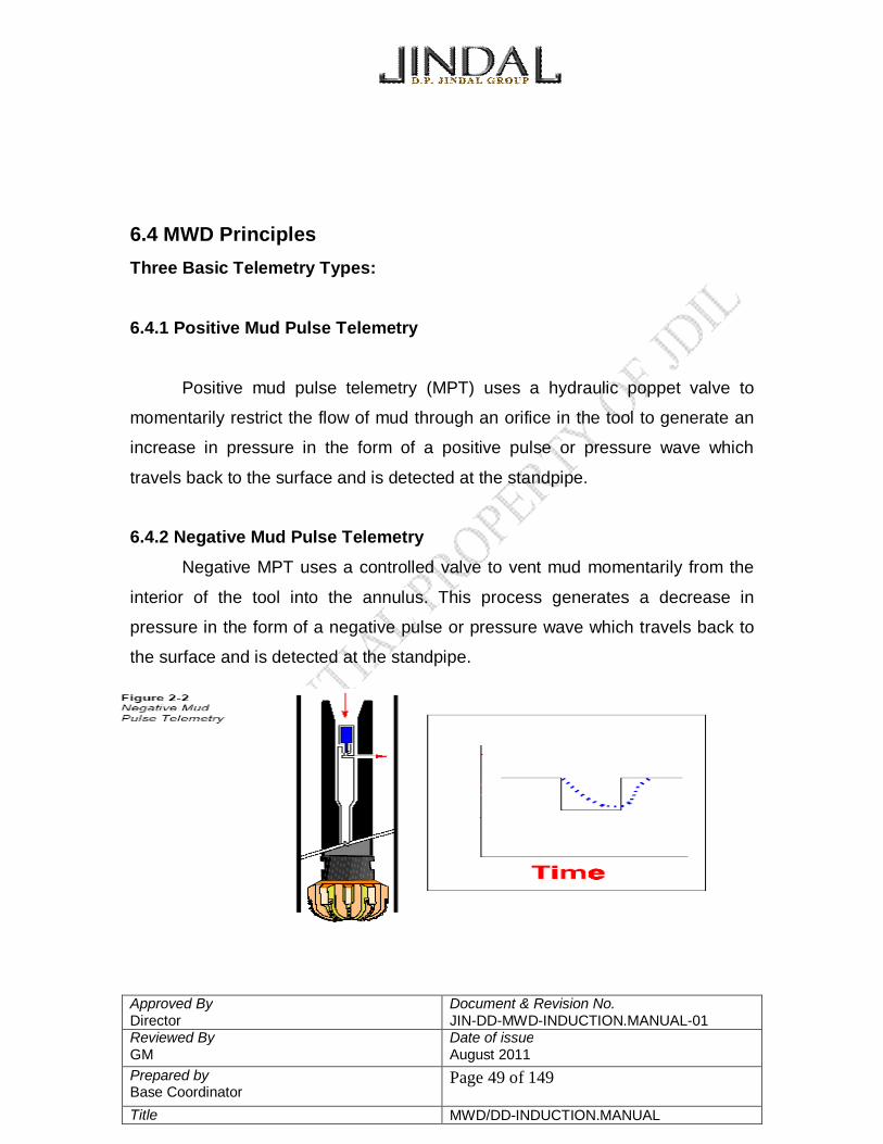
6.4.2 Negative Mud Pulse Telemetry
Negative MPT uses a controlled valve to vent mud momentarily from the
interior of the tool into the annulus. This process generates a decrease in
pressure in the form of a negative pulse or pressure wave which travels back to
the surface and is detected at the standpipe.

Approved By Director
Document & Revision No. JIN-DD-MWD-INDUCTION.MANUAL-01
Reviewed By GM
Date of issue August 2011
Prepared by Base Coordinator
Page 50 of 149
Title MWD/DD-INDUCTION.MANUAL
6.4.3 Continuous Wave Telemetry
Continuous wave telemetry uses a rotary valve or “mud siren” with a
slotted rotor and stator which restricts the mud flow in such a way as to generate
a modulating positive pressure wave which travels to the surface and is detected
at the standpipe.
6.4.4 Electromagnetic Telemetry
The electromagnetic telemetry (EMT) system uses the drill string as a
dipole electrode, superimposing data words on a low frequency (2 - 10 Hz)
carrier signal. A receiver electrode antenna must be placed in the ground at the
surface (approximately 100 meters away from the rig) to receive the EM signal.
Offshore, the receiver electrode must be placed on the sea floor. Currently,
besides a hardwire to the surface, EMT is the only commercial means for MWD
data transmission in compressible fluid environments common in underbalanced
drilling applications. While the EM transmitter has no moving parts, the most

Approved By Director
Document & Revision No. JIN-DD-MWD-INDUCTION.MANUAL-01
Reviewed By GM
Date of issue August 2011
Prepared by Base Coordinator
Page 51 of 149
Title MWD/DD-INDUCTION.MANUAL
common application in compressible fluids generally leads to increased
downhole vibration. Communication and transmission can be two-way i.e.
a) downhole to uphole: Mud telemetry
b) uphole to downhole. The EM signal is attenuated with increasing well
depth and with increasing formation conductivity.
Approved By Director
Document & Revision No. JIN-DD-MWD-INDUCTION.MANUAL-01
Reviewed By GM
Date of issue August 2011
Prepared by Base Coordinator
Page 52 of 149
Title MWD/DD-INDUCTION.MANUAL
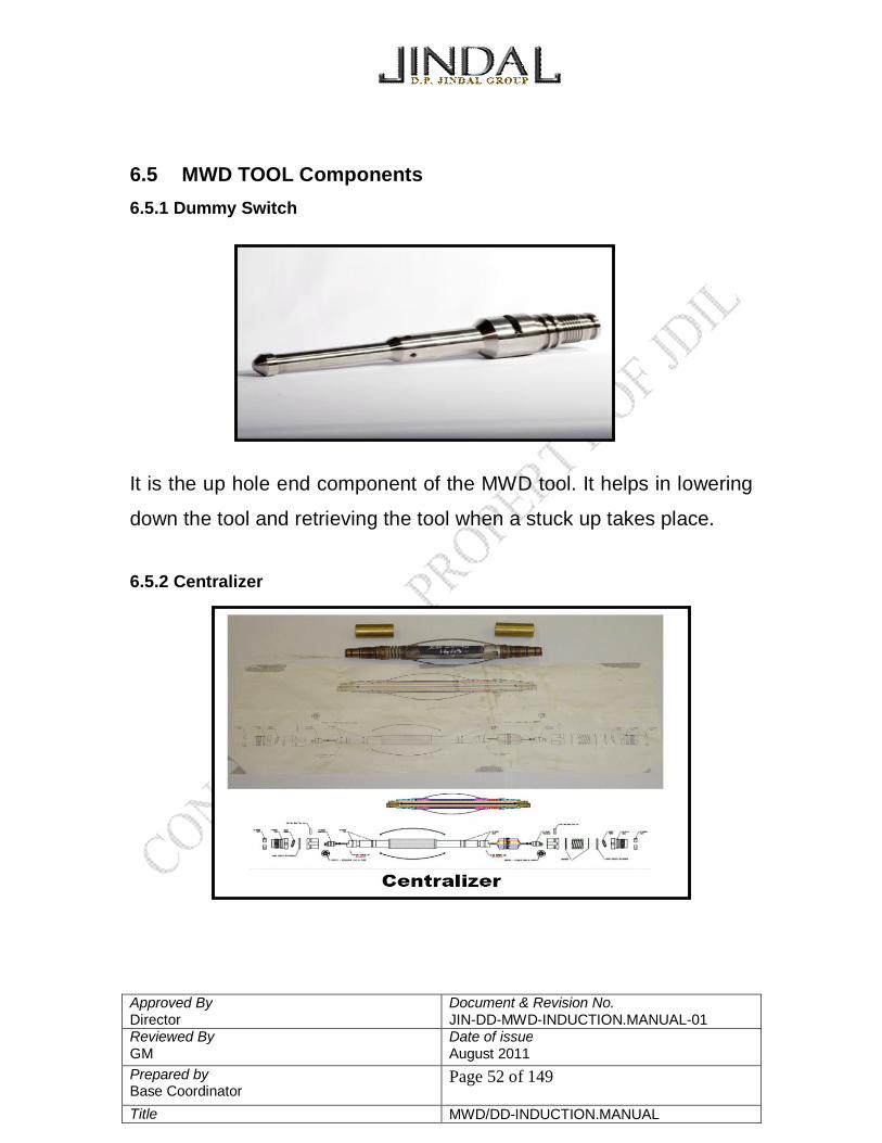
6.5 MWD TOOL Components 6.5.1 Dummy Switch
It is the up hole end component of the MWD tool. It helps in lowering
down the tool and retrieving the tool when a stuck up takes place.
6.5.2 Centralizer

Approved By Director
Document & Revision No. JIN-DD-MWD-INDUCTION.MANUAL-01
Reviewed By GM
Date of issue August 2011
Prepared by Base Coordinator
Page 53 of 149
Title MWD/DD-INDUCTION.MANUAL
Centralizer has the function of keeping the MWD tool centered inside the Monel.
It prevents excessive lateral vibrations and also provides electrical connections
between battery, electronics and pulsar driver.
6.5.3 Electronics Module
The electronics module can be easily identified as it is the longest component in
the MWD string. Electronics module is also known as the Direction and
Inclination (DnI) module and it is the brain of the string. It is majorly composed of
a circuit with three important sensors temperature, accelerometers and
magnetometers being at 1.6 feet away from the downhole end of the DnI module.
Sensors
A) Temperature
Our tool works efficiently within the range 0- 150 degree Celsius hence it is
important that the DnI module houses a temperature sensor. The temperature
sensor is activated earlier than the accelerometers and magnetometers are.
B) Accelerometer
Accelerometers are used to measure the earth’s local gravitational field.
Each accelerometer consists of a magnetic mass (pendulum) suspended in an
electromagnetic field. Gravity deflects the mass from its null position. Sufficient
Approved By Director
Document & Revision No. JIN-DD-MWD-INDUCTION.MANUAL-01
Reviewed By GM
Date of issue August 2011
Prepared by Base Coordinator
Page 54 of 149
Title MWD/DD-INDUCTION.MANUAL
current is applied to the sensor to return the mass to the null position. This
current is directly proportional to the gravitational force acting on the mass. The
gravitational readings are used to calculate the hole inclination, toolface, and the
vertical reference used to determine dip angle.
There are 3 accelerometers aligned in the 3 axis directions to read the
gravity field individually in the X, Y, Z direction and then the effective gravity field
is calculated.
C) Magnetometer
Magnetometers are used to measure the earth’s local magnetic field. Each
magnetometer is a device consisting of two identical cores with a primary winding
around each core but in opposite directions. A secondary winding twists around
both cores and the primary winding. The primary current (excitation current)
produces a magnetic field in each core. These fields are of equal intensity, but
opposite orientation, and therefore cancel each other out such that no voltage is
induced in the secondary winding. When the magnetometer is placed in an
external magnetic field which is aligned with the sensitive axis of the
magnetometer (core axis), an unbalance in the core saturation occurs and a
voltage directly proportional to the external field is produced in the secondary
winding. The measure of voltage induced by the external field will provide precise
determination of the direction and magnitude of the local magnetic field relative to
the magnetometer’s orientation in the borehole.
There are 3 magnetometers aligned in the 3 axis directions to read the
magnetic field individually in the X, Y, Z direction and then the effective magnetic
field is calculated.

Approved By Director
Document & Revision No. JIN-DD-MWD-INDUCTION.MANUAL-01
Reviewed By GM
Date of issue August 2011
Prepared by Base Coordinator
Page 55 of 149
Title MWD/DD-INDUCTION.MANUAL
6.5.4 Gamma Tool
The tool consists simply of a highly sensitive gamma ray detector in the form of a
scintillation counter. The scintillation counter is composed of a thalium activated
single sodium iodide crystal backed by a photomultiplier. When a gamma ray
strikes the crystal a small flash of light is produced. This flash is too small to be
measured using conventional electronics. Instead, it is amplified by a
photomultiplier, which consists of a photocathode and a series of anodes held at
progressively higher electrical potentials, all of which are arranged serially in a
high vacuum.
The Gamma tool can be easily identified in the string as it is the shortest
component of the string.
Approved By Director
Document & Revision No. JIN-DD-MWD-INDUCTION.MANUAL-01
Reviewed By GM
Date of issue August 2011
Prepared by Base Coordinator
Page 56 of 149
Title MWD/DD-INDUCTION.MANUAL
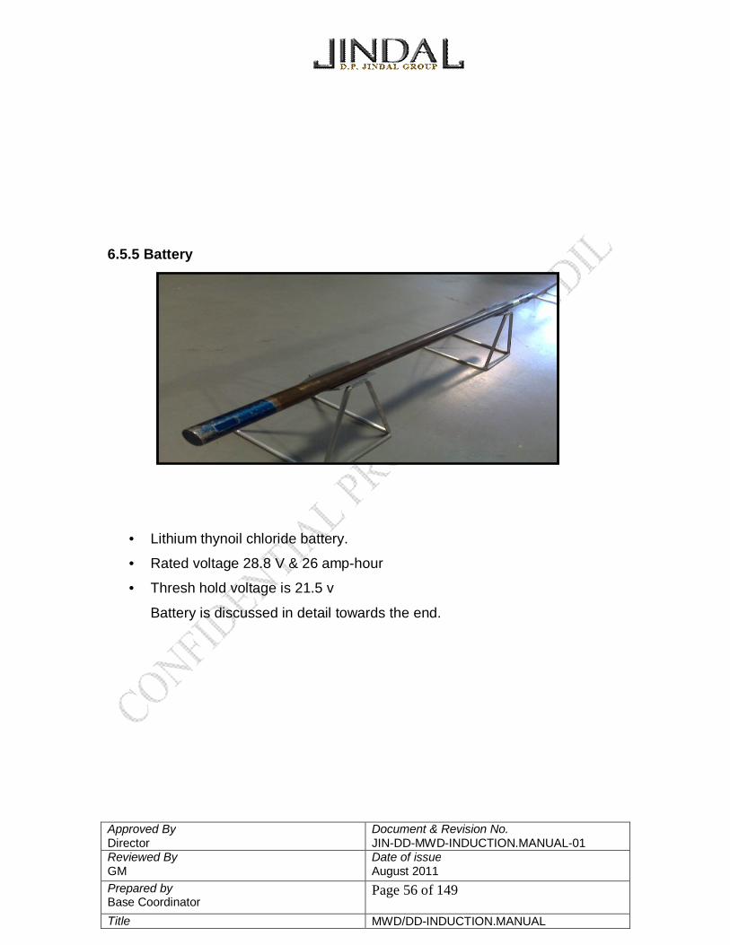
6.5.5 Battery
• Lithium thynoil chloride battery.
• Rated voltage 28.8 V & 26 amp-hour
• Thresh hold voltage is 21.5 v
Battery is discussed in detail towards the end.

Approved By Director
Document & Revision No. JIN-DD-MWD-INDUCTION.MANUAL-01
Reviewed By GM
Date of issue August 2011
Prepared by Base Coordinator
Page 57 of 149
Title MWD/DD-INDUCTION.MANUAL
6.5.6 Pulsar Driver System
The Pulsar driver can be identified easily in the MWD string as it has screen
housing at the down hole end. The pulsar driver system possessed by Jindal has
a BL 3 phase DC motor which is controlled by the Electronic module through the
electrical pin connections present in the various MWD tool components. The up
hole connections of pulsar driver system have 6 pin male connection. The down
hole end is connected to the stringer assembly.
The pulsar driver is divided into 3 major sections
A) Snubber assembly- mainly consists of the electric circuit
B) Oil fill housing- mainly houses the 3 phase BL DC motor and capacitor bank.
C) Screen housing- consists mainly of the bellow, servo shaft, servo poppet.

Approved By Director
Document & Revision No. JIN-DD-MWD-INDUCTION.MANUAL-01
Reviewed By GM
Date of issue August 2011
Prepared by Base Coordinator
Page 58 of 149
Title MWD/DD-INDUCTION.MANUAL
6.5.7 STRINGER ASSEMBLY
The different components used to assemble the stringer assembly are shown in
the diagram below. The components of the stringer assembly are 4, 5, 6, 7, 8, 6, 10, polypack and
servo orifice. The piston shaft is hollow and on top of the shaft is fixed lower piston cap, poly
pack, upper piston cap and servo orifice in sequence. This assembly is then
placed inside the helix/stinger. This combination is then screwed in the
planum/stringer barrel which has a spring inside. A poppet is now attached to the
end of the stringer shaft. Our stringer assembly is now prepared. The stringer
assembly is attached to the downhole end of the pulsar driver.

Approved By Director
Document & Revision No. JIN-DD-MWD-INDUCTION.MANUAL-01
Reviewed By GM
Date of issue August 2011
Prepared by Base Coordinator
Page 59 of 149
Title MWD/DD-INDUCTION.MANUAL
Fig Stringer Assembly

Approved By Director
Document & Revision No. JIN-DD-MWD-INDUCTION.MANUAL-01
Reviewed By GM
Date of issue August 2011
Prepared by Base Coordinator
Page 60 of 149
Title MWD/DD-INDUCTION.MANUAL
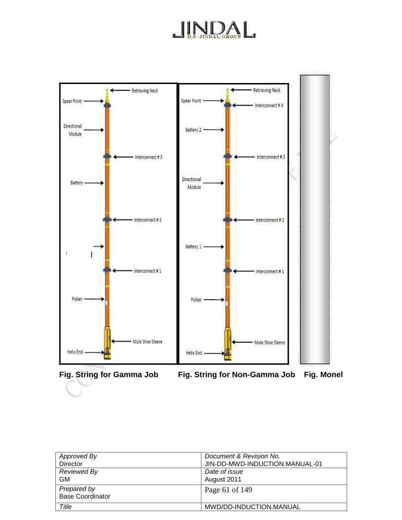
6.6 MWD STRING 6.6.1 Gamma Job
D/I Module – Centralizer – Battery Module – Centralizer – Gamma Module –
Centralizer – Pulsar Driver – Stringer Assembly
6.6.2 Non-Gamma Job Battery 2 – Centralizer – D/I Module – Centralizer – Battery 1 – Centralizer –
Pulsar Driver – Stringer Assembly
Approved By Director
Document & Revision No. JIN-DD-MWD-INDUCTION.MANUAL-01
Reviewed By GM
Date of issue August 2011
Prepared by Base Coordinator
Page 61 of 149
Title MWD/DD-INDUCTION.MANUAL
Fig. String for Gamma Job Fig. String for Non-Gamma Job Fig. Monel

Approved By Director
Document & Revision No. JIN-DD-MWD-INDUCTION.MANUAL-01
Reviewed By GM
Date of issue August 2011
Prepared by Base Coordinator
Page 62 of 149
Title MWD/DD-INDUCTION.MANUAL
6.7 Placing MWD tool in the BHA
Fig. showing
the placement
of MWD
1. Above the SDMM, a
Universal Bent Housing
Orienting (UBHO) sub is
torqued. A mule shoe is
oriented inside the
UBHO in such a way that the
landing key is in line with the
bend of the mud motor.
This process is called
scribing.
2. The mule shoe is then
fixed inside the UBHO with
the help of 2 set screws.
3. Non Magnetic Drill
Collars are torqued above
the UBHO.

Approved By Director
Document & Revision No. JIN-DD-MWD-INDUCTION.MANUAL-01
Reviewed By GM
Date of issue August 2011
Prepared by Base Coordinator
Page 63 of 149
Title MWD/DD-INDUCTION.MANUAL
4. The programmed MWD tool with the helix facing down hole are lifted from the
spear point of dummy switch and lowered into the NMDC. The helix of the MWD
tool sits inside the landing key of mule shoe (in the UBHO).
5. Further one more NMDC is torque, if required, followed by Drill collars and
Heavy weight drill pipe.
6.8 KINTEC PIN CONNECTIONS

Approved By Director
Document & Revision No. JIN-DD-MWD-INDUCTION.MANUAL-01
Reviewed By GM
Date of issue August 2011
Prepared by Base Coordinator
Page 64 of 149
Title MWD/DD-INDUCTION.MANUAL
6.9 Working of MWD tool
When the pumps are switched on the single axised accelerometer in the
snobber assembly of the Pulser Driver senses the vibrations and sends
the same message to the DnI through pin 7. The DnI awaits for a few seconds known as the transmit delay time before
it activates the pulsing action in the Pulsar Driver through pin 6. The to and fro motion of the servo poppet produces the pressure waves
which contains the data from the DnI module. The amplitude of these
pressure waves are very low and are required to be amplified in order to
be transmitted to the transducer at the surface.
PIN 1 GROUND 0 V PIN 2 BATTERY-1 28.8V PIN 3 BATTERY-2 28.8V PIN 4 B- BUS 27.9V PIN 5 Q-BUS 0-2.5V PIN 6 PULSE 05V PIN 7 FLOW 05V PIN 8 GAMMA 05V PIN 9 MOD-1 ---- PIN 10 MOD-2 ----

Approved By Director
Document & Revision No. JIN-DD-MWD-INDUCTION.MANUAL-01
Reviewed By GM
Date of issue August 2011
Prepared by Base Coordinator
Page 65 of 149
Title MWD/DD-INDUCTION.MANUAL
The amplification of the pressure amplitude is done by the stringer
assembly. When the tool is placed in the muleshoe, the servo poppet as
well as the stringer poppet are in the closed position. When mud flows through the NMDC housing the MWD tool, there is a
pressure difference because of which the stringer poppet retracts and
compresses the spring in the plenum. The stringer poppet is now in the
open position. The 3- phase DC motor controls the movement of the servo poppet. The
servo poppet when is in the open position provides a free path to the mud
to enter the plenum. Hence the pressure inside and outside are balanced. The spring will now try to reach its least energy position as all forces are
balanced except for the spring force. Hence the spring now expands
pushing the poppet back to its closed position. This causes an increase in
pressure & cause the pulse magnitude to increase. The servo poppet closes and the process is repeated. The servo orifice on the upper piston cap allows the mud to bleed during
the compression and expansion of the spring. The magnified pulse now travels through the mud in the drill string and is
read by the pressure transducer.

Approved By Director
Document & Revision No. JIN-DD-MWD-INDUCTION.MANUAL-01
Reviewed By GM
Date of issue August 2011
Prepared by Base Coordinator
Page 66 of 149
Title MWD/DD-INDUCTION.MANUAL
6.10 MWD Tool Retrieval Equipment
The outer diameter of our tool is 1.88” hence in the case of a stuck up it is
possible for us to retrieve the MWD string with the help of equipments above.
There are two types of assembly for tool retrieval depending upon the
angle of the well. Well the angle of inclination is less than 45 degrees we
use a overshot, sinker bar and cross over.
For angles more than 45 degrees we use a spring jar which provides
flexibility to the assembly.
The selection of overshot bell is integral and the difefernt sizes of overshot
bells are 1.75”, 2” and 2.25”

Approved By Director
Document & Revision No. JIN-DD-MWD-INDUCTION.MANUAL-01
Reviewed By GM
Date of issue August 2011
Prepared by Base Coordinator
Page 67 of 149
Title MWD/DD-INDUCTION.MANUAL
The assembly is run along with the CCL (casing collar locator) tool of the
wireline unit.
Go down with the wireline unit while monitoring tension and depth.
One it has reached the bottom, rather found the tool, move up and down
while monitoring the tension.
6.11 TOOLFACE The angle at which the steering tool is pointed is termed as the toolface.
Fig. Toolface
Toolfaces are used to change the hole direction. The low angles the
accelerometers are not as accurate as the magnetometers so low angle toolface
are based on magnetic readings. Using magnetic toolfaces means pointing the
steering tool in the direction of the target.

Approved By Director
Document & Revision No. JIN-DD-MWD-INDUCTION.MANUAL-01
Reviewed By GM
Date of issue August 2011
Prepared by Base Coordinator
Page 68 of 149
Title MWD/DD-INDUCTION.MANUAL
Once the direction/azimuth is achieved the toolface changes from magnetic
toolface to gravity toolface. The well bore has achieved direction and can be
moved left or right of the original direction.
6.12 Fluidic Vortex
The fluidic pulser generates a vortex within a chamber by momentarily
restricting the mud flow, thus creating a turbulent flow regime. The resulting
change in pressure loss can be switched on and off rapidly, circa 1millisecond,
and the resultant pressure wave created can be of high amplitude (145 psi).
MWD directional survey instrument is used to monitor the direction (magnetic)
and inclination (the angle of the tool's long axis from vertical) of the borehole.
In the MWD drilling environment, there are many sources of magnetic
interference that can cause inaccurate directional measurements. A
ferromagnetic steel object that is placed in a magnetic field will become
magnetized. The amount of induced magnetism is a function of the external field
strength and magnetic permeability of the object. In order to prevent magnetic
interference, the directional survey instrument is housed in a nonmagnetic
stainless steel collar. The MWD tool is usually arranged in a section of the
bottom-hole assembly (BHA) which is made up of a series of non-magnetic
collars to reduce the impact of the drilling assembly's steel components on the
magnetic field at the location of the survey sensor.
It is possible to optimize the position of the survey instrument by
estimating the pole strength for various BHA configurations, based upon
downhole field measurements. However, even if the correct non-magnetic collar

Approved By Director
Document & Revision No. JIN-DD-MWD-INDUCTION.MANUAL-01
Reviewed By GM
Date of issue August 2011
Prepared by Base Coordinator
Page 69 of 149
Title MWD/DD-INDUCTION.MANUAL
spacing is used, there could still be other sources of magnetic interference which
will cause erroneous directional readings. These include “hot spots” in the non-
magnetic steel or areas of mechanical damage caused by rethreading/welding or
manufacturing impurities. A continual quality assurance procedure ensures that
such anomalies are not present in MWD collars and stabilizers. More
significantly, other BHA components may be made of magnetic material and/or
already has magnetic anomalies that affect azimuth readings. Other sources of
magnetic interference may be caused by proximity to iron and steel
magnetic materials from previous drilling or production operations, magnetic
properties of the formation, and concentrations of magnetic minerals (iron pyrites,
etc) in excess of six percent.
6.13 Azimuth Correction Technique
It is often advantageous to reduce the number of non-magnetic drill collars
so that the directional and formation evaluation sensors can be located closer to
the bit. (This also eliminates the extra cost of using monel collars.) This will assist

Approved By Director
Document & Revision No. JIN-DD-MWD-INDUCTION.MANUAL-01
Reviewed By GM
Date of issue August 2011
Prepared by Base Coordinator
Page 70 of 149
Title MWD/DD-INDUCTION.MANUAL
in real-time decision making by allowing readings to be made as soon as
possible following formation penetration. To address this problem, a number of
methods have been devised for making corrections to magnetic surveys. The
following correction techniques are designed to reduce the influence of spurious
magnetic fields associated with the BHA:
Magnetic Azimuth Correction Algorithm
This is a proprietary method by which magnetic azimuth can be calculated
in the event that the z-axis magnetometer reading is corrupted by a spurious
longitudinal field resulting from an insufficient length of nonmagnetic BHA
components. The tool senses such a spurious field as a bias on the z-
magnetometer measurement. The method requires the operator to specify
expected values for total magnetic field and dip angle, and it then computes the
azimuth angle which is consistent with a magnetic field vector as close as
possible to the expected value. Accuracy of this azimuth angle is dependent on
the accuracy of the input nominal values for the earth's magnetic field and gravity
field. The corrected magnetic azimuth accuracy is dependent on the surface
location of the well and the direction and inclination that is being drilled. At higher
latitudes and higher inclinations and the farther the direction is from north or
south, the accuracy of the corrected azimuth will degrade. The operator will have
to decide whether to use the corrected azimuth or the uncorrected azimuth based
on concerns for azimuth accuracy.
Rotation Algorithm
This is a refinement to the Magnetic Azimuth Correction Algorithm above,
which makes use of downhole tool rotation to reduce errors caused by bias in x-
axis and y-axis magnetometers, in addition to the z-axis magnetometer bias.
Also, accelerometer bias errors on the x-axis and y-axis can be reduced with this
procedure. Such biases may be caused not only by calibration drift, but also by
magnetic hot spots in the drill collar or by magnetic junk affixed to the outside of

Approved By Director
Document & Revision No. JIN-DD-MWD-INDUCTION.MANUAL-01
Reviewed By GM
Date of issue August 2011
Prepared by Base Coordinator
Page 71 of 149
Title MWD/DD-INDUCTION.MANUAL
the collar. This method requires a minimum of three surveys at different tool face
angles, to define a circle centered at a point which represents the transverse
biases. This method can reduce errors caused by magnetic anomalies which
rotate as the survey tool is rotated. It does not reduce errors which do not rotate,
such as interference from an adjacent casing string.
6.14 Basic Hydraulics 6.14.1 System Pressure
System pressure is the pressure felt throughout the system. While drilling, the
cuttings must be removed either with the help of water, weighted mud, foam,
steam or air. The column of water or mud in the hole is called the drilling fluid and
they exert a hydraulic pressure against the formation. This is known as the
hydrostatic head or hydrostatic pressue. It is usually measured in pounds per
square inch
Bernoulli’s principle
Fig. Hydraulic system with a restriction

Approved By Director
Document & Revision No. JIN-DD-MWD-INDUCTION.MANUAL-01
Reviewed By GM
Date of issue August 2011
Prepared by Base Coordinator
Page 72 of 149
Title MWD/DD-INDUCTION.MANUAL
The diagram illustrates 3 different pressure regions. The pressure in or after the
restriction is higher. In the area of restriction the pressure is relatively low. After
the restricted area the pressure returns to normal.
6.14.2 Annular Velocity
It is the velocity the fluid is flowing with in closed pressure system such as the
annulus. Erosion on the metal surfaces of the MWD tool as well as around areas
where restriction occurs are directly related to annular velocity and the amount
od solids in the mud. There are two flow regimes Turbulent and Laminar.
Turbulent flow oocurs when the velocity reaches a critical point known as the
critical velocity. Below the critical velocity we have a laminar flow of mud.
Fig. Example of turbulent and laminar flow
A more turbulent flow gives better hole cleaning. But turbulent flows can cause
washout of the hole.

Approved By Director
Document & Revision No. JIN-DD-MWD-INDUCTION.MANUAL-01
Reviewed By GM
Date of issue August 2011
Prepared by Base Coordinator
Page 73 of 149
Title MWD/DD-INDUCTION.MANUAL
6.14.3 Pressure Pulses
Most tools today use bernoulli’s principle to communicate between tool and the
surface computer. The data from the tool is encoded as pressure pulses and
decoded at the surface. The high pressure pulses are formed due to the
restriction in the hydraulic system. A sensor at the surface converts the
mechanical pressure into electrical signals. The electrical signal is send to signal
converter and to a computer. The surface computer decodes the data and
displays it on the screen.
6.14.4 Drilling Fluid
In the oil and gas industry the drilling fluid is referred to mud exceptions being
foam and air. The fluid column (mud) acts as part of the communication system
also known as the qbus.
The mud system controls the quality of the mud and is critical for successfully
transmitting MWD data. Thick or more viscous mud affect pulses by creating less
sharp peaks. Sometimes when gas or mud enters the mud it gives symptoms
that look like pulse failure.
6.15 Factors Affecting the Mud Pulse There are a number of sources of interference in the MWD drilling
environment, although the main ones are as follows: 6.15.1 Mud Pump Noise
Excessive noise, either from the mud pumps or high torque mud motors
can, in rare instances, create unacceptable signal to noise ratios. In order to
prevent this, some MWD companies deploy surface measurement of pump
strobes in order to characterize a mud pump signature. This is then used in the

Approved By Director
Document & Revision No. JIN-DD-MWD-INDUCTION.MANUAL-01
Reviewed By GM
Date of issue August 2011
Prepared by Base Coordinator
Page 74 of 149
Title MWD/DD-INDUCTION.MANUAL
surface decoder as a pump subtraction filter. In many cases, the pump
subtraction filter can be used to detect premature pump damage before any other
physical signs are available.
6.15.2 Rig and Drill string Noise
Drill string vibration will, typically, generate high frequency noise which
can lead to a dramatic deterioration of the transmitted signal. Very often, by
simply making adjustments to the WOB and RPM, it is possible to avoid
damaging critical torsional and lateral resonance. A number of vibration
prediction programs are available which can estimate critical RPM for a given
drilling assembly. It is also possible to use high frequency surface measurement
devices, such as the Baker Hughes INTEQ ADAMS and DynaByte technology
provided by the Drilling Dynamics Group. (The Drilling Dynamics Group within
Baker Hughes INTEQ uses EXLOG (now part of Baker Hughes INTEQ), ARCO
and ELF patented surface measurement technologies).
6.16 Reliability Reliability is the probability of a product performing without failure, a
specified function under given conditions for a given period of time. A unit of
measure is Mean Time Between Failure (MTBF). In this respect, the reliability
standard is expressed as follows:
Reliability = MTBF = Operating Hours (Perfect Hours)
Failure
Factors Affecting Reliability:
• Shock and Vibration
• Telemetry System

Approved By Director
Document & Revision No. JIN-DD-MWD-INDUCTION.MANUAL-01
Reviewed By GM
Date of issue August 2011
Prepared by Base Coordinator
Page 75 of 149
Title MWD/DD-INDUCTION.MANUAL
• Downhole Temperature
• Drilling Practices
• Complexity of Tool
• Service Company Quality Assurance (TQM)
• Competition
• Training

Approved By Director
Document & Revision No. JIN-DD-MWD-INDUCTION.MANUAL-01
Reviewed By GM
Date of issue August 2011
Prepared by Base Coordinator
Page 76 of 149
Title MWD/DD-INDUCTION.MANUAL
7. TENSOR MWD BATTERY MANUAL
GE Power Systems supplies this manual for information and insight to our
clients on safe handling and transportation of Lithium battery products. This
manual contains information supplied by battery and battery pack manufacturers
and suppliers. The information contained within is easily obtained via the Internet
or by contacting the Battery Suppliers listed in the front of the manual.
http://www.spectrumbatteries.com/supp2.htm
http://www.spectrumbatteries.com/Prod_in/chart.htm http://www.batteryeng.com/safety.htm http://www.spectrumbatteries.com/Prod_in/passivation_information.htm http://www.batteryeng.com/func_perf.htm
PLEASE NOTE AND READ – THE ABOVE HYPERLINKS.
These hyperlinks can be used to access more detailed data about battery
manufacturers and battery pack assembly companies..
SAFE STORAGE AND HANDLING
In most cases, improper handling and storage, resulting in such problems
as overheating and short-circuiting cause damage to batteries. The common
safety practices have been outlined below; safety precautions to take with regard
to all aspects of battery storage and handling.
Storage:

Approved By Director
Document & Revision No. JIN-DD-MWD-INDUCTION.MANUAL-01
Reviewed By GM
Date of issue August 2011
Prepared by Base Coordinator
Page 77 of 149
Title MWD/DD-INDUCTION.MANUAL
1. Shelf Batteries should be stored in their original shipping boxes, if possible, to
keep them isolated from each other, preventing external short circuits. Do not
store batteries loosely, and do not place batteries on metal surfaces.
2. Temperatures and Environment
Batteries should be stored in a cool, dry, well-ventilated area with an
optimal storage temperature range of 0-25_C. If prolonged storage is anticipated,
batteries should be protected against excessive humidity. This will prevent
moisture from forming an electrical pathway between the feed-through terminal
and battery cover, which can lead to severe galvanic corrosion of the feed-
through pin, thus compromising the hermeticity of the battery.
3. Hazard Consideration
Lithium battery storage areas should be clearly marked and provided with
“Lith-X” fire extinguishing material. Batteries might burst if subjected to excessive
heating. In case of fire, only “Lith-X” fire extinguisher should be used, as water
will cause exposed lithium to ignite. Signs should clearly state – WATER IS NOT
TO BE USED IN CASE OF FIRE.
LITHIUM BATTERY SAFETY MANUAL The following paragraphs will discuss the safe handling of Lithium Thionyl Chloride (LTC) batteries under the abnormal hazardous conditions of:
1. Leaking or venting batteries, 2. Hot batteries,
3. Exploding batteries, 4. Lithium fires.
Personnel Protective Equipment Required:

Approved By Director
Document & Revision No. JIN-DD-MWD-INDUCTION.MANUAL-01
Reviewed By GM
Date of issue August 2011
Prepared by Base Coordinator
Page 78 of 149
Title MWD/DD-INDUCTION.MANUAL
Safety Glasses, Rubber Gloves, Helmet with full face shield, Flak Jacket
with gloves, Riot Shield, Respirator with canisters for Acid Gases or full-
face respirator with acid gas cartridges.
Other Equipment Required:
Infrared Temperature Probe, Sodium Carbonate (Soda Lime) or Sodium
Bicarbonate (Baking Soda), Vermiculite, Fire Extinguisher containing Lith-
X Graphite powder, extended Non-conductive pliers or tongs, Thermal
resistant gloves (welding gloves).
7.1 PROCEDURE FOR LEAKING OR VENTED BATTERIES
Leaking or vented batteries should be isolated from personnel and
equipment. If possible, the area should be vented to the outside. Prior to
handling, the temperature of the batteries should be checked with a remote-
sensing device such as an infrared temperature probe. If the batteries are at
ambient temperature, they should be handled with rubber gloves or non-
conductive pliers or tongs and placed in plastic bags containing Sodium
Carbonate. Spilled electrolyte should be absorbed with Sodium Carbonate and
placed in plastic bags. All bags should be placed in a sealed and labeled drum
with Vermiculite or other non-flammable cushioning material such as sand or
Sodium Carbonate to cushion the batteries. These materials should be disposed
as previously discussed under Safe Disposal in the Lithium Battery Safety
Manual.

Approved By Director
Document & Revision No. JIN-DD-MWD-INDUCTION.MANUAL-01
Reviewed By GM
Date of issue August 2011
Prepared by Base Coordinator
Page 79 of 149
Title MWD/DD-INDUCTION.MANUAL
7.2 PROCEDURE FOR HOT BATTERIES As soon as a hot battery is detected, all personnel should be
evacuated from the area. The temperature of the battery should be
monitored with a remote-sensing device such as an infrared temperature
probe. The area should remain evacuated until the battery has cooled to
ambient temperature. When the battery has returned to ambient temperature,
it can be handled by an operator wearing protective equipment (face shield,
flak jacket and gloves) with non-conductive pliers or tongs. The batteries
should be placed in plastic bags containing Sodium Carbonate and then
placed in labeled drums containing Vermiculite or other non-flammable
cushioning material such as sand or Sodium Carbonate. These materials
should be disposed of as previously discussed under Safe Disposal in the
Lithium Battery Safety Manual.
OR
If liquid nitrogen is available, the battery should be placed in liquid
nitrogen/or dry ice with a pair of tongs. Once frozen, the battery must be
dissected and the components neutralized in a soda ash water bath. Unused or
partially used Lithium must be set aside to hydrolyze.
If the battery is thawed and not dissected, the battery will return to its
original state of being hot (short-circuited) and may explode.
If the battery vents or explodes, it should be handled with the procedure
for vented or exploding batteries.
7.3 PROCEDURE FOR EXPLODING BATTERIES

Approved By Director
Document & Revision No. JIN-DD-MWD-INDUCTION.MANUAL-01
Reviewed By GM
Date of issue August 2011
Prepared by Base Coordinator
Page 80 of 149
Title MWD/DD-INDUCTION.MANUAL
If a battery explodes, all personnel should be evacuated from the area.
The area should be vented to the outside until the pungent odor is no longer
detectable. If the expelled material is on fire, it should be treated as described
below in the procedure for a Lithium fire. After the residue has cooled, it can be
absorbed with Sodium Carbonate and placed in plastic bags. All bags should be
placed in a sealed and labeled drum with Vermiculite or other non-flammable
cushioning material such as sand or Sodium Carbonate to cushion the s. These
materials should be disposed as previously described under Safe Disposal in the
Lithium Battery Safety Manual.
7.4 PROCEDURE FOR A LITHIUM FIRE Evacuate the premises. Personnel should avoid breathing the smoke from
a lithium fire, as it may be corrosive. Trained personnel wearing self-contained
breathing apparatus or a respirator with acid gas cartridges should use Lith-X fire
extinguishers to fight the fire. When the fire is extinguished and the residue
cooled, it can be absorbed with Sodium Carbonate and placed in plastic bags. All
bags should be placed in a sealed and labeled drum with Vermiculite or other
non-flammable cushioning material such as sand or Sodium Carbonate to
cushion the s. These materials should be disposed properly.
7.5 LITHIUM BATTERY SAFETY With proper use and handling, lithium batteries have demonstrated an
extensive safety record. The success and wide use of lithium batteries is partially
because they contain more energy per unit weight than conventional batteries.
However, the same properties, which result in a high energy density also,
contribute to potential hazards if the energy is released at a fast and uncontrolled

Approved By Director
Document & Revision No. JIN-DD-MWD-INDUCTION.MANUAL-01
Reviewed By GM
Date of issue August 2011
Prepared by Base Coordinator
Page 81 of 149
Title MWD/DD-INDUCTION.MANUAL
rate. In recognition of the high-energy content of lithium systems, safety has
been incorporated into the design and manufacture of all batteries. However,
abuse or mishandling of lithium batteries can still result in hazardous conditions.
The information provided here is intended to give users some guidelines to safe
handling and use of lithium batteries.
Abuse
In general, the conditions that cause damage to batteries and jeopardize
safety are summarized on the label of each. These conditions include:
• Short Circuit
• Charging
• Forced Over-discharge
• Excessive heating or incineration
• Crush, puncture, or disassembly
Very rough handling or high shock and vibration could result in damage.
NOT DESIGNED FOR CHARGING OR RECHARGING
PRODUCT NAME: Lithium Oxyhalide Primary Battery (MWD)
CHEMISTRY SYSTEM: Lithium/thionyl Chloride
CHEMICAL FORMULAS: Li/ SOCI2
TOXIC, CAUSTIC OR IRRITANT CONTENT
Important Note: The battery container should not be opened or incinerated since
the following ingredients contained within could be harmful under some
circumstances if exposed.
In case of accidental ingestion of a cell or its contents, obtain prompt medical
advice.
MATERIALS

Approved By Director
Document & Revision No. JIN-DD-MWD-INDUCTION.MANUAL-01
Reviewed By GM
Date of issue August 2011
Prepared by Base Coordinator
Page 82 of 149
Title MWD/DD-INDUCTION.MANUAL
Lithium is included in this section due to its vigorous reaction with water
forming a caustic hydroxide.
Lithium (Li)
Thionyl Chloride (SOCI2)
7.6 STORAGE AND DISPOSAL TIPS STORAGE: Store in a cool place but prevents condensation on the batteries.
Elevated temperatures can result in shortened battery life.
FIRE: If batteries are directly involved in a fire, DO NOT USE WATER, CO2, DRY CHEMICAL OR HALOGEN EXTINGUISHERS. A Lith-X (graphite base) fire
extinguisher or material is the only recommended extinguishing media for fires
involving lithium metal or batteries. If a fire is in an adjacent area, and batteries are
packed in their original containers, the fire can be fought based on fueling material,
e.g., paper, and plastic products. Avoid fume inhalation.
DISPOSAL: DO NOT INCINERATE or subject batteries to temperatures in excess of
212°F (100°C). Such abuse can result in loss of seal, leakage, and/or explosion.
Dispose of in accordance with appropriate Federal, State, and Local regulations.
Section 10 Version 2.00; February, 2002; BattM 16
HANDLING AND USE PRECAUTIONS
MECHANICAL CONTAINMENT: Encapsulation (some potting) will not allow for
expansion. Such enclosure can result in high-pressure explosion from heating due to
inadvertent charging or high temperature environments (i.e., in excess of 100°C).
SHORT-CIRCUIT: Batteries should always be packaged and transported in such a
manner as to prevent direct contact with each other. Short-circuiting will cause heat
and reduce capacity. Jewelry, such as rings and bracelets, should be removed or
insulated before handling the batteries to prevent inadvertent short-circuiting through

Approved By Director
Document & Revision No. JIN-DD-MWD-INDUCTION.MANUAL-01
Reviewed By GM
Date of issue August 2011
Prepared by Base Coordinator
Page 83 of 149
Title MWD/DD-INDUCTION.MANUAL
contact with the battery terminals. Burns to the skin may result from the heat
generated by a short- circuit.
CHARGING: These batteries are not designed to be charged or recharged. To do so
may cause the batteries to leak or explode.
OTHER: If soldering or welding to the terminals or case of the battery is required,
exercise proper precautions to prevent damage to the battery which may result in
loss of capacity, seal, leakage, and/or explosion. DO NOT SOLDER to the case.
Batteries should not be subjected to excessive mechanical shock & vibration.
7.7 HANDLING AND INSPECTION GUIDELINES
The most frequent forms of abuse can easily be identified and controlled in the
workplace. All spirally, wound batteries are internally protected against the hazards
associated with short circuits. This is accomplished by incorporating a fast acting fuse
under the terminal cap. It is our experience that inadvertent short circuits (resulting in
open fuses) are the largest single cause of field failures. Batteries with open fuses
(characterized by zero voltage) should be disposed of or returned to the
manufacturer for rework. Never attempt to remove the terminal cap or replace the
internal fuse.
Problems associated with shorting as well as other hazardous conditions can be
greatly reduced by observing the following guidelines:
• Cover all metal work surfaces with an insulating material.
• The work area should be clean and free of sharp objects that could puncture
the insulating sleeve on the battery.
• Never remove the shrink-wrap from a battery pack.

Approved By Director
Document & Revision No. JIN-DD-MWD-INDUCTION.MANUAL-01
Reviewed By GM
Date of issue August 2011
Prepared by Base Coordinator
Page 84 of 149
Title MWD/DD-INDUCTION.MANUAL
• All persons handling batteries should remove jewelry items such as rings,
wristwatches, pendants, etc. that could be exposed to the battery terminals.
• If batteries are removed from their original packages for inspection, they should
be neatly arranged to preclude shorting.
• Individual cells should be transported in plastic trays set on pushcarts. This will
reduce the chances of the batteries being dropped on the floor, causing physical
damage.
• All inspection tools (calipers, rulers, etc.) should be made from non-conductive
materials, or covered with a non-conductive tape.
• Batteries should be inspected for physical damage. Batteries with dented cases
or terminal caps should be inspected for electrolyte leakage. If any is noted, the
battery should be disposed of in the proper manner.
STORAGE
Batteries should be stored in their original containers. Store batteries in a
well ventilated, cool, dry area. Store batteries in an isolated area, away from
combustible materials. Never stack heavy objects on top of boxes containing
lithium batteries to preclude crushing or puncturing the case.
7.8 HANDLING DURING PRODUCT ASSEMBLY
• All personnel handling batteries should wear appropriate protective equipment
such as safety glasses.
• Do not solder wires or tabs directly to the battery. Only solder to the leads
welded to the battery by the manufacturer.

Approved By Director
Document & Revision No. JIN-DD-MWD-INDUCTION.MANUAL-01
Reviewed By GM
Date of issue August 2011
Prepared by Base Coordinator
Page 85 of 149
Title MWD/DD-INDUCTION.MANUAL
• Never touch a battery case directly with a hot soldering iron. Heat sinks should
be used when soldering to the tabs, and contact with the solder tabs should be
limited to a few seconds.
• Batteries should not be forced into (or out of) battery holders or housings. This
could deform the battery pack causing an internal short circuit, or fracturing the
glass to metal hermetic seal.
• All ovens or environmental chambers used for testing batteries should be
equipped with an over-temperature controller to protect against excessive heat.
• Do not connect batteries of different chemistries together.
• Do not connect batteries of different size together.
• Do not connect old and new batteries together.
• Consult manufacturer before encapsulating batteries during discharge.
Batteries may exceed their maximum rated temperature if insulated.

Approved By Director
Document & Revision No. JIN-DD-MWD-INDUCTION.MANUAL-01
Reviewed By GM
Date of issue August 2011
Prepared by Base Coordinator
Page 86 of 149
Title MWD/DD-INDUCTION.MANUAL
8. QMWD – SAP SYSTEM
8.1 System Description: The surface system measures mud pulses in the mud column using a
pressure transducer that decodes the MWD survey, tool faces and logging
information. In addition, the surface system tracks the depth of the drilling
assembly, saves data, and displays information for system operators. The SAI
(Safe Area Interface) acts as the system hub in the safe area and performs the
following functions:
The SAI contains a receiver board (qBUS Node 05) that digitizes and
decodes input from the surface sensors including the mud pulse pressure
transducer, hook load transducer, and depth encoder.
The SAI is connected to the hazardous area sensors through certified
intrinsic safety barriers.
The qNIC, now included in the SAI, performs interface functions between
the Safe Area Personal Computer and the qBus system on the SAI. The
SAPC must be running qMWD/W32 software.
The SAI transmits display information for the display side of the legacy
DRT as a display option. It is connected to the legacy DRT through
intrinsic safety barriers.
The SAI contains an RJ-45 to fiber optic Ethernet converter that is
connected to a router and PC in the safe area via RJ-45 Ethernet cables.
It may connect to a Rig Floor Display via fiber optic cable or copper cable
option.
The SAI connects to the MWD electronics for configuration.

Approved By Director
Document & Revision No. JIN-DD-MWD-INDUCTION.MANUAL-01
Reviewed By GM
Date of issue August 2011
Prepared by Base Coordinator
Page 87 of 149
Title MWD/DD-INDUCTION.MANUAL
The SAI downloads high-speed data from the PWR tool memory to the
PC.
NOTE: A hot-work permit must be obtained before dumping data from the
PWR tool.
The mud pulse pressure transducer is a 4-20 mA output device with a
range of 0-6,000 psi that senses the pressure in the mud column. Its
output is converted to pressure pulses and decoded by the SAI. It is
mounted into the standpipe.
The Rig Floor Display is designed and certified for use in Zone 1
environments and receives Ethernet data via a fiber optic cable or copper
cable. Power requirements are 120 or 240 VAC. A compass rose is
displayed that is similar to the qMWDPC/W32 software.
The legacy DRT (Driller’s Remote Terminal) is an intrinsically safe Receiver
and Display used with the Safe Area Supply Box. These legacy devices may be
used as Rig Floor Displays with the SAI. The legacy DRT receives power and
data from the SAI through intrinsic safety barriers via the SAI to RT cable, 250
feet (PN 384022). If depth data is required, the system can be run in one of two :
Configuration 1: Directional only with depth input from an outside source.
NOTE: If a depth system is required then depth input may be supplied a serial
connection to a WITS system (Well Information Transfer System).
Configuration 2: Depth tracking, with the J Box, hook load pressure transducer,
and depth encoder added to the system with accompanying cables.

Approved By Director
Document & Revision No. JIN-DD-MWD-INDUCTION.MANUAL-01
Reviewed By GM
Date of issue August 2011
Prepared by Base Coordinator
Page 88 of 149
Title MWD/DD-INDUCTION.MANUAL
The type of hook load & pressure transducer used depends on the point of
connection:
The hydraulic sensor type is connected to the hydraulic input of the weight
indicator on the rig floor. The hydraulic sensor is a 4-20 mA output device
with a range of 2,000 psi. The tension meter type, called a hook load
sensor, is connected to the drill line on the dead line anchor.
Both sensors detect whether the entire drill string or just the Kelly or top
drive is
o attached to the traveling block. Hook load sensors allow the system
measure
o Weight On Bit (WOB). Either type of hook load sensor may be used
in a
o hazardous area.
The Geolograph encoder tracks movement of the Geolograph line, which
moves up and down with the traveling block. Movement of the Geolograph
line is quated to measured depth. Output of the encoder is a 2-line,
quadrature-phased electrical
o signal, which allows the system to measure the amount and
direction of block
o travel.
Geolograph encoders are used in the hazardous area. However, the
preferred method for measuring depth is to place an encoder at the water
union of the drawworks drum. Drawworks encoders are always installed
on the right-hand side of the drawworks as viewed from the rotary table.

Approved By Director
Document & Revision No. JIN-DD-MWD-INDUCTION.MANUAL-01
Reviewed By GM
Date of issue August 2011
Prepared by Base Coordinator
Page 89 of 149
Title MWD/DD-INDUCTION.MANUAL
A drawworks encoder tracks the movement of the drum as the drilling line
is spooled off or on and converts the rotational motion to linear depth. Two
(2) magnetic pickups detect phase difference in the signal output as the
disk rotate, which creates a signal pulse that indicates direction of travel.
Like the Geolograph encoder, the drawworks encoder is also used in the
hazardous area.
8.2 Toolface Offset Procedure
With the tool assembled, to contain at least the survey electronics module
and the pulser module, connect the programming cable to the
programming plug and connect to the uphole end of the MWD tool. Set the
tool on V-blocks in a near horizontal position and orient the muleshoe key
slot so it faces UP.
Double click on the TFO Procedure Icon to start the Tool Face Offset
Procedure.
With both the downhole tool and the remote terminal connected to the
system, the program should quickly address both systems. If either of the
two modules is not connected, the routine will look for the absent node and
then enter into the routine with a warning screen. The Warning Screen will
identify which of the systems it could not locate and ask the operator if he
would like to Abort, Retry or Ignore. Depending on which routine the
operator wishes to follow, select the appropriate option.

Approved By Director
Document & Revision No. JIN-DD-MWD-INDUCTION.MANUAL-01
Reviewed By GM
Date of issue August 2011
Prepared by Base Coordinator
Page 90 of 149
Title MWD/DD-INDUCTION.MANUAL
If the operator wishes to ‘Zero the Gravity Toolface Angle’, once the tool is
located, then the operator can select the appropriate option and continue to
the screen that will allow this procedure.
DOUBLE CHECK TO INSURE THAT THE KEYWAY IS LOCATED IN THE
UP POSITION. This procedure is performed specifically in the DownHole
Tool. Select the first command to Zero the Gravity Toolface Angle. Notice
the number in the second line, Gravity Toolface Angle, which is below the
update line, will change to zero. Simultaneously, the value of the
Instrumentation Mounting Offset will be changed from its previous value to
the previous value of the Gravity Toolface Angle. Also, that the value of that
space will be added to the Total Toolface Correction.
At this point, if the operator knows the DAO (Driller’s Assembly Offset), then
enter this value into the system. The DAO value maps to the surface gears
Remote Terminal.
Quit this routine. IT IS IMPORTANT TO QUIT THE ROUTINE BEFORE
DISCONNECTING THE PROGRAMMING CABLE. OTHERWISE, THE
DiAA LABEL WILL REMAIN ON AND THE TOOL SENSORS WILL WORK
CONTINUOUSLY. If the batteries are connected to the tool and the
connection is broken before quitting the routine, the batteries will have to be
disconnected from the electronics to reset the tool. All corrections and
configuration files will remain stored in the processor, but the TFO
correction routine should be run again if any connections are broken and/or
re-torqued. The offset may be different.
DO NOT MAKE ANY ASSUMPTIONS.

Approved By Director
Document & Revision No. JIN-DD-MWD-INDUCTION.MANUAL-01
Reviewed By GM
Date of issue August 2011
Prepared by Base Coordinator
Page 91 of 149
Title MWD/DD-INDUCTION.MANUAL
Disconnect the programming cable and assemble the spear-point on the top
of the downhole tool.

Approved By Director
Document & Revision No. JIN-DD-MWD-INDUCTION.MANUAL-01
Reviewed By GM
Date of issue August 2011
Prepared by Base Coordinator
Page 92 of 149
Title MWD/DD-INDUCTION.MANUAL
8.3 Summary of the features of qMWD V 01.30
I. New Features A. qMWD
1. qMWDPC / RT - Drawworks encoder depth tracking
NOTE: Version qMPRX-D3 Vb1.61f or later must be installed in the MPRx 05 of
the RT for drawworks capability.
2. qMWDPC - Utilities for:
a. Drawworks encoder calibration
b. Geolograph encoder calibration
c. Hookload calibration
3. qMWDPC - Database size reducing features:
a. Allows user to set a minimum distance of pipe movement before a
new depth record is written
b. Allows user to set a lower and upper limit on the depths allowed to
write database records, (prevents records with 0 depth in database).
c. User has the option to mark multiple gammas at the same depth as
bad when written to the database, (can be undone in LogView)
d. User can set limits on gamma data which will cause out of range
gammas to be marked bad
4. qMWDPC – Audible alarms will be made for the following events:
a. Flow off – 2 dings
b. Flow on – 1 ding
c. Sync detected – 1 ding
d. End of survey – 1 ding

Approved By Director
Document & Revision No. JIN-DD-MWD-INDUCTION.MANUAL-01
Reviewed By GM
Date of issue August 2011
Prepared by Base Coordinator
Page 93 of 149
Title MWD/DD-INDUCTION.MANUAL
e. RT power failure – 3 dings
f. RT power restored – 1 ding
g. QDT_EDR Interface loss of communication with EDR – 3 dings
5. qMWDPC - A function has been provided to convert measured depth to TVD
and vice versa
6. qMWDPC - Surveys are now fully editable and new ones can be added. The
survey calculation window will automatically update TVD when a new survey is
entered or received from the RT; survey closures will automatically be calculated
and stored whenever a new survey is received. Tie-ins can now be edited in the
survey calculation window.
NOTE: LogView V02.01d updates only new surveys, so any edits made to
surveys that had already been loaded into a log database will not be updated. To
get these changes into the log database, the user will have to start a new log
database. LogView VB2.01e and later reads ALL surveys in when an update is
performed.
7. qMWDPC – the maximum number of TFAs possible based on print
width and print header type selected is now automatically computed for the users
selection
8. QDT_EDR Interface
a. Inclination and Azimuth will be output to the WITS port to 1 decimal
place.
b. Fixed problem that was preventing communications with the Pason
EDR in half-duplex mode
B. MWDRoll32
Win9x / WinNT 4.0 version of MWDRoll test

Approved By Director
Document & Revision No. JIN-DD-MWD-INDUCTION.MANUAL-01
Reviewed By GM
Date of issue August 2011
Prepared by Base Coordinator
Page 94 of 149
Title MWD/DD-INDUCTION.MANUAL
NOTE: MWDRoll32 MUST NOT be run at the same time as any qMWD app as it
changes the PC’s LnkA and this will have disastrous effects on any qMWD/W32
app running at the same time. MWDRoll32 does, however change it back when it
exits, so all qMWD/W32 apps will then run as normal.
C. MemoryIO/W32
If MemoryIO/W32 is on the PC where this CD is being installed it will
be automatically updated to V01.01.
NOTE: Do NOT attempt to re-load MemoryIO/W32 V01.00 on this PC after
loading qMWD V01.30 as it will cause qMWD/W32 apps to fail.
II. Bug Fixes and Enhancements
8.4 Summary of features of qMWDPC V 01.20

Approved By Director
Document & Revision No. JIN-DD-MWD-INDUCTION.MANUAL-01
Reviewed By GM
Date of issue August 2011
Prepared by Base Coordinator
Page 95 of 149
Title MWD/DD-INDUCTION.MANUAL
1. Survey will now print in meters when meters are selected as the unit.
2. Only good surveys will be printed by the survey print function.
3. Several bugs with ASCII logging files in association with logging in variable
units have been fixed
4. Reduced the size of the scroll view for the gamma window to prevent the user
being locked out for long periods when scrolling
5. Added Pumps Up Time and Pumps Down Time to pumps on and off event log
messages stored in C:\MWDEvent.Log to allow user to more easily track
circulating hours. Pump accumulators will be in the next release.
6. Extensive work to prevent the writing of bad records to the data base when
RT has a power failure has been done.
7. Temperature was not being stored with the gamma records
8. An invalid error message box was being displayed every time a database was
opened
in the year 2000. This will no longer be displayed.
9. Added the ability to display TVD in the Telemetry window
10. Corrected survey calculations to take absolute value of course length when
calculating dogleg severity.
III. Changes since Beta qMWD Vb1.30d
A. MWDRoll32
1. Puts gamma on the display
2. When Azimuth is 0 for inclination during the roll test, the beta of
MWDRoll32 was not treating readings near 359.9 as close to 0, but as 359.x
away from 0 and failing the tool. This has been fixed.

Approved By Director
Document & Revision No. JIN-DD-MWD-INDUCTION.MANUAL-01
Reviewed By GM
Date of issue August 2011
Prepared by Base Coordinator
Page 96 of 149
Title MWD/DD-INDUCTION.MANUAL
B. qMWD/W32
1. qMWDCnfg
a. will not attempt to send “DSTy” (Depth Sensor Type) to an MPRx with an ASW
earlier than 1.61f
b. fixed 4 problems with implementation of access control using capability codes
c. new defaults for access control settings have been supplied
2. qMWDPC
a. It will not start another copy of the calibration utilities if they are already running
b. The ‘Recalc’ button has been restored to the survey calculation window. A
checkbox has been provided to allow the user to prevent recalculation on every
survey edit (see help).
c. The accept/reject survey dialogs will no longer stack up. If a new survey has
been received before the displayed accept/reject dialog has been responded to,
the default action will be performed (see help)
d. Will no longer attempt to write an invalid record to the database, but will inform
the operator and log the error
e. A crash that occurred when the user pressed the Exit button in the depth
setting dialog before the operation was complete has been fixed.
f. Fixed the archive database template archive.db. The user was unable to open
an archive database when Kilodekanewtons were selected as the units of force
in qVarUnits. The error message was ‘No Current Record’.
3. TFO Procedure - Fixed error that was setting IMO in MPTx when user was
setting DAO in MPRx
4. QDT_EDR Interface - Fixed problem that was preventing communications with
the Pason EDR in half-duplex mode.

Approved By Director
Document & Revision No. JIN-DD-MWD-INDUCTION.MANUAL-01
Reviewed By GM
Date of issue August 2011
Prepared by Base Coordinator
Page 97 of 149
Title MWD/DD-INDUCTION.MANUAL
C.Recorder to Log Merge Utility Beta
A new version, Vb1.00b of this utility that allows plotting of recorded data
has been included for evaluation. This version will allow the user to create a new
data set consisting of recorded data only or to merge the recorded data with an
existing data set containing pulsed data. Please let us know how this utility works
and what we can do to improve it, if necessary.
8.5 Summary of New Features in qMWD V02.02 Common Features to V02.00 2-Bay and 3-Bay Systems A. Features available with upgraded PC software for all versions of firmware
1. qMWD/W32 software runs under Windows 2000 Pro SP4 and XP Pro SP2
2. qMWDCnfg/W32 has transparent plug and play, giving the customer the ability
to use any combination of downhole and receiver firmware seamlessly.
3. Configurations are written to a database.
4.Greatly enhanced configuration print with the option for a summary or complete
report.
5. The ability to send and receive WITS data via TCP/IP as well as via serial
COM.
6. Support for the qVision rig floor display.
7. The qW32 Server automatically finds the COM port that the qNIC is connected
to an accumulated Pumps Time Window that gives the user the ability to track
and edit pump times on a daily or per job basis.
9. The default for Flow Evaluation time is set to 25 seconds to prevent short flow
on and off cycles which may cause the downhole tool to quit sending surveys.

Approved By Director
Document & Revision No. JIN-DD-MWD-INDUCTION.MANUAL-01
Reviewed By GM
Date of issue August 2011
Prepared by Base Coordinator
Page 98 of 149
Title MWD/DD-INDUCTION.MANUAL
B. Features available with upgraded PC software and receiver firmware
1. The ability to work seamlessly with LogView II, the log data storage, downhole
data recorder retrieval and data editing application.
2. The ability to work seamlessly with RTView, the remote real-time log plotting
and final presentation log application with the ability to produce PDF files and to
print to any Windows compatible printer.
3. Any number of remote computers can display a real-time log with sensor data
depth offset with RTView.
4. A percent decode variable is computed by the receiver and displayed in
qMWDPC/W32.
5. The option to defeat or change the sliding window for the averaging of decode
quality and confidence values.
6. The ability to issue a command to the receiver to force it to stop decoding
pulses
C. Features available with upgraded surface software and firmware requiring upgraded downhole firmware
1. The option to detect drill string rotation and eliminate toolface updates when
rotating.
2. The option to set up the system to send and detect a sync sequence after
every complete Toolface/Logging sequence.
3. The option to repeat the same survey data sequence a number of times to
assist in survey decoding when drilling in lost circulation conditions.
4. The option to force the receiver to stop attempting to decode data and go into
resync mode at any time if the resync feature is enabled.
5. Short Flow Off Downlink allows the user to defeat the transmission of survey
data and to limit the number of Toolface/Logging sequences after a pump cycle

Approved By Director
Document & Revision No. JIN-DD-MWD-INDUCTION.MANUAL-01
Reviewed By GM
Date of issue August 2011
Prepared by Base Coordinator
Page 99 of 149
Title MWD/DD-INDUCTION.MANUAL
9. TRU-VU USER GUIDE
9.1 TRU VU DATA WISE SYSTEM SETUP Do not start up the computer, plugged into the TRU VU system.
On the laptop have the external comport (gold wire cable) plugged into the
bottom. USB comport. With the desktop you don't use the external cable,
you have two comports already. Put the TRU VU key in.
Now start up the computer and enter the TRU VU program by the short
cut on the desk top.
On the welcome to TRU VU screen: select "new" if you are starting a new
well.
Create a new well name , job #, or you can "browse" for a old well that you
want
To open in the database. "proceed" confirm "yes" if that’s the well you
want.
*for a new well have a "check mark" in the require initial setup file.
"browse"
Highlight "india" "proceed". This is a pre-configured setup so you don't
have to create one .
If this is a new well being created click "yes" for first time that the program
has been started.
*If this is a well that already has been started from before click "no"
because all your settings will be changed.

Approved By Director
Document & Revision No. JIN-DD-MWD-INDUCTION.MANUAL-01
Reviewed By GM
Date of issue August 2011
Prepared by Base Coordinator
Page 100 of 149
Title MWD/DD-INDUCTION.MANUAL
If this is an old well that you are re-opening, you can now plug in the Tru
vu system to your computer.
*the black serial "T" cable plugs into the back of the data wise box into
RS232 port which will plug into comport 1. The grey q-bus cable plugs into
the comport 2. The other end plugs into the q-bus port on the saps.
If it is a new well a TRU VU setup screen will come up. This is where you
add all your well information.
LOADER SCREEN
Goto: "browse", highlight on "india", "open", "load"
SURVEY SCREEN
You want "minimum radius of curvature"
Put in information for :"proposed direction(vs)", "proposed declination",
"dogleg" set
At 30, "survey to bit", "gamma to bit". (leave "wet connect to bit" and "gsi
to bit" at
Zero, (unless you know what they are or mean?)
Hit "set" after changing each one of them.
USER VARIABLES SCREEN
Do not touch.
DATABASE SCREEN
Change units to "metric".
Change granularity to ".2" increments
Leave your start depth at zero, because if you put a depth in there you will
not be able to enter a tie in survey, or any survey before that depth you
have entered.

Approved By Director
Document & Revision No. JIN-DD-MWD-INDUCTION.MANUAL-01
Reviewed By GM
Date of issue August 2011
Prepared by Base Coordinator
Page 101 of 149
Title MWD/DD-INDUCTION.MANUAL
CLICK ON "SAVE DATA" BEFORE YOU LEAVE THIS SCREEN. ASSOCIATIONS SCREEN
Make sure you are in "custom configuration"
Have: an "x" infront of these associations by highlighting them. Then click
on "connect to input" which will put a check mark infront of "connect to
input".
TRU VU DATA WISE SYSTEM SETUP AZM
MWD LISTENER TYPE 1
TAG 2 (AZM)
BLOCK INPUT
TRU VU CONDUIT
ENCODER/COUNTER 1
DIP
MWD LISTENER TYPE 1
TAG 7 (DIPA)
GAMMA
MWD LISTENER TYPE 1
TAG 8 (GAMA)
HOOKLOAD WHEN YOU CALIBRATE THE HOOKLOAD YOU WILL HAVE A

Approved By Director
Document & Revision No. JIN-DD-MWD-INDUCTION.MANUAL-01
Reviewed By GM
Date of issue August 2011
Prepared by Base Coordinator
Page 102 of 149
Title MWD/DD-INDUCTION.MANUAL
TRU VU CONDUIT "CHECK MARK" INFRONT OF "SCALE INPUT VALUE"
ALSO.
ANALOG 1
H TOTAL
MWD LISTENER TYPE 1
TAG 12 (MAGF)
INCLINATION
MWD LISTENER TYPE 1
TAG 3 (INC)
PUMPS OFF TIME (MWD)
MWD LISTENER TYPE 1
MUD PUMPS OFF TIME
PUMPS ON TIME (MWD)
MWD LISTENER TYPE 1
MUD PUMPS ON TIME
PUMP PRESSURE
MWD LISTENER TYPE 1
TAG 10 (PMPP)
TOOL TEMPERATURE
MWD LISTENER TYPE 1
TAG 4 (TEMP)
TOOL VOLTAGE
MWD LISTENER TYPE 1
TAG 13 (BATV)
TOOLFACE GRAVITY
MWD LISTENER TYPE 1

Approved By Director
Document & Revision No. JIN-DD-MWD-INDUCTION.MANUAL-01
Reviewed By GM
Date of issue August 2011
Prepared by Base Coordinator
Page 103 of 149
Title MWD/DD-INDUCTION.MANUAL
TAG 5 (GTFA)
TOOLFACE MAGNETIC
MWD LISTENER TYPE 1
TAG 6 (MTFA)
TRU VU DATA WISE SYSTEM SETUP DEVICES SCREEN
This should be all configured already in the "india" setup file. If not have these
set:
DEVICE:
CLICK ON MWD LISTENER TYPE 1
SETUP: ALWAYS "SAVE" YOUR DATA IF YOU LISTENER ONLY CHANGE ANY OF YOUR
CONNECTION: CONFIGURATIONS, BEFORE YOU GOTO COM 2 THE NEXT STEP.
HAVE: TIMEOUT COUNT SET AT [10]
SPEED [9600]
LISTENING ID [7]
PUMP STATUS [1]
DEBUG MODE [0]
*LEAVE THE REST ALONE.
NEXT DEVICE:
NETWORK
SETUP:
BLANK
CONNECTION:
[NONE]

Approved By Director
Document & Revision No. JIN-DD-MWD-INDUCTION.MANUAL-01
Reviewed By GM
Date of issue August 2011
Prepared by Base Coordinator
Page 104 of 149
Title MWD/DD-INDUCTION.MANUAL
NEXT DEVICE:
TRU VU DATABOX
SETUP:
8 ANALOGS/4 DIGITALS
CONNECTION:
ISA CARD/PCMCIA CARD
*HAVE DATABOX ENABLED [OFF]
NEXT DEVICE:
TRU VU CONDUIT
SETUP:
SERIAL MODE
CONNECTION:
COM 1
*HAVE TIMEOUT COUNT [10]
SPEED [9600]
TACHOMETER CLIP TIME [2 TO 65 SECONDS] [30]
COUNTER +/- JUMP MAXIMUM [5000]
These are the comports where the information is coming from. If you don't
have that symbol showing up. You have a com port not configured right. If there
is a grey symbol with a blue clock beside it, it means your system is not hooked
up to a com port or you have to unplug the TRU VU system from your com ports,
exit out all programs, and restart your computer. Open up the job you want and
then reconnect your TRU VU system to your com ports.
TRU VU DATA WISE SYSTEM SETUP

Approved By Director
Document & Revision No. JIN-DD-MWD-INDUCTION.MANUAL-01
Reviewed By GM
Date of issue August 2011
Prepared by Base Coordinator
Page 105 of 149
Title MWD/DD-INDUCTION.MANUAL
"F3" SCREEN "GRAPH 1" is where you want "gamma" on the left hand side in #1 and "rop" on
right hand side in #5. To setup the screen, click on the "wrench" now you will see
Slot #1 flashing this is where you enter "gamma" by going up to the top right and
Click on the down arrow below "depth" arrow. Scroll down until you see "gamma"
Highlight it. Now you will want to set the scale. Go down and click at the right "0"
Now you can enter your gamma maximum scale at "100". Now you will want to
set up ROP.
Goto #5 and click on it. Now it will flash. Go up and click on the down arrow
And scroll down till you see "ROP". Highlight it, and now set your scale by
clicking on the right "0" and put in "150" for a maximum rop scale. Then go up top
and click on the wrench again. Now it is set up.
If you need to edit the graph. Click on the "pencil" the gamma screen will
now be ready to be edited. With the mouse click on where you want to edit from
and scroll down slowly to where you want to stop editing from. Then go and click
on the "disk" picture to save the new edit or click the "trash can" to go back to the
original way it was. Then click on the pencil to finish editing. If you want to edit
"ROP" click on the pencil ,then click on the #"5" at the bottom. Now you are ready
to edit.
Click on the "disk" to save or "trash can" to restore to old data. When done
click on "pencil" to finish.
9.2 PRINTING PLOTS MD GAMMA, MD ROP PLOTS
Click on the "printer", now you will be in the "graph point" screen.
At the top you want to be in:

Approved By Director
Document & Revision No. JIN-DD-MWD-INDUCTION.MANUAL-01
Reviewed By GM
Date of issue August 2011
Prepared by Base Coordinator
Page 106 of 149
Title MWD/DD-INDUCTION.MANUAL
GRAPH 1: TRACES 1-3, API, 8", MD/TVD, 2 DATA TRACKS (SHOULD BE
TOP OF LIST.)
Be careful not to click on the "locked" bottom, it will lock you out from editing the
plotter setup. (there are notes on how to un-lock it on page 7).
In the general options screen you want:
Click on the "pencil" so you can edit the information.set your depths
AXIS: MD
Res: 1 to 500 or 700, user defined (larger the number the shorter the plot)
Big header path: c:\tvc\headers\header.big Header path: c:\tvc\headers\headers.md.txt Trailer path: c:\tvc\headers\headers.apg
If your not in these, click "browse" find them, highlight them. "Open" now it will be
There.
Casing symbol 0.25
Heavy div 5
Annotation 25
FRONT 10
CHECKED MARKED SURVEY -1
CHECKED MARKED COMMENTS -1
In the tracks and traces screen you want:
Click on these to highlight them, so then you can see what they are configured to.
TRACKS

Approved By Director
Document & Revision No. JIN-DD-MWD-INDUCTION.MANUAL-01
Reviewed By GM
Date of issue August 2011
Prepared by Base Coordinator
Page 107 of 149
Title MWD/DD-INDUCTION.MANUAL
#1: LINEAR GRID(0.000)
0 TO 2.5
LINEAR GRID MD
TRU VU DATA WISE SYSTEM SETUP
BLACK NONE CYAN
2 4
0
4
TRACES
#1: [GR1, TR1] (#1 LINEAR GRID (0.000)
[GR1, TR1] #1: LINEAR GRID(0.00)
0 0 UNAVERAGED
....,THICK BLUE
NONE
TRACKS
#2: AXIS ANNOTATION (2.500)
2.5 TO 3.25
AXIS ANNOTATION MD
BLACK NONE BLUE
0 0
0
0
TRACES
#2: [GR1, TR2] (#1: LINEAR GRID (0.000)
[GR1, TR2] #1: LINEAR GRID (0.000)

Approved By Director
Document & Revision No. JIN-DD-MWD-INDUCTION.MANUAL-01
Reviewed By GM
Date of issue August 2011
Prepared by Base Coordinator
Page 108 of 149
Title MWD/DD-INDUCTION.MANUAL
0 0 UNAVERAGED
. ., THICK BLACK
NONE
TRACKS
#3: LINEAR GRID (3.250)
3.25 TO 5.75
LINEAR GRID MD
BLACK NONE CYAN
2 4
0
4
TRACES
#3: [GR1, TR3] (#1: LINEAR GRID (0.000)
[GR1, TR3] #1: LINEAR GRID (0.000)
0 0 UNAVERAGED
. . . . ., THICK GREEN
NONE
TRACKS
#4: SURVEY COMMENT (5.750)
5.75 TO 8
SURVEY COMMENT DEFAULT
BLACK NONE GREEN
0 0
0
0
TRU VU DATA WISE SYSTEM SETUP PAGE 6

Approved By Director
Document & Revision No. JIN-DD-MWD-INDUCTION.MANUAL-01
Reviewed By GM
Date of issue August 2011
Prepared by Base Coordinator
Page 109 of 149
Title MWD/DD-INDUCTION.MANUAL
TRACES
#4: [GR1, TR5] (#3: LINEAR GRID (3.250)
[GR1, TR5] #3: LINEAR GRID (3.250)
0 0 UNAVERAGED
...., THICK BLUE
NONE
TRACKS
#5: COMMENT (5.750)
5.75 TO 8
COMMENT MD
BLACK NONE BLUE
0 0
0
0
TRACES
#5: [GR1, TR3] (#3: LINEAR GRID (3.250)
[GR1, TR3] #3: LINEAR GRID (3.250)
0 0 UNAVERAGED
. ..., THICK BLACK
NONE
TRACES
#6: [GR1, TR3] (#3: LINEAR GRID (3.250)
[GR1, TR3] #3: LINEAR GRID (3.250)
0 0 UNAVERAGED
. . . . ., THICK GREEN
NONE

Approved By Director
Document & Revision No. JIN-DD-MWD-INDUCTION.MANUAL-01
Reviewed By GM
Date of issue August 2011
Prepared by Base Coordinator
Page 110 of 149
Title MWD/DD-INDUCTION.MANUAL
NOW YOU CAN "CLICK" ON THE "PRINTER" SYMBOL TO PRINT THE PLOT.
TO PRINT PLOTS TVD GAMMA, TVD ROP PLOTS IN THE GENERAL OPTIONS SCREEN YOU WANT:
CLICK ON THE "PENCIL" SO YOU CAN EDIT THE INFORMATION.
SET YOUR DEPTHS
AXIS: TVD RES: 1 TO 500 OR 700, USER DEFINED (LARGER THE NUMBER THE
SHORTER THE PLOT)
BIG HEADER PATH: C:\TVC\HEADERS\HEADER.BIG HEADER PATH: C:\TVC\HEADERS\HEADERS.TVD.TXT TRAILER PATH: C:\TVC\HEADERS\HEADERS.APG
IF YOUR NOT IN THESE CLICK "BROWSE" FIND THEM, HIGHLIGHT THEM.
"OPEN" NOW IT WILL BE
THERE.
CASING SYMBOL 0.25
HEAVEY DIV 5
ANNOTATION 25
FRONT 10
CHECKED MARKED SURVEY -1
CHECKED MARKED COMMENTS -1

Approved By Director
Document & Revision No. JIN-DD-MWD-INDUCTION.MANUAL-01
Reviewed By GM
Date of issue August 2011
Prepared by Base Coordinator
Page 111 of 149
Title MWD/DD-INDUCTION.MANUAL
TRU VU DATA WISE SYSTEM SETUP PAGE 7
TRACKS: CHANGE "TRACK #1 TO TVD AXIS
CHANGE "TRACK #2 TO TVD AXIS
CHANGE "TRACK #3 TO TVD AXIS
KEEP #4 TO DEFAULT CHANGE "TRACK #5 TO TVD AXIS
*KEEP THE REST OF THE TRACES THE SAME..
*WHEN THE TRACKS AND TRACES ARE SET UP YOU ONLY HAVE TO CHANGE YOUR: DEPTHS, AXIS TO MD OR TVD, "HEADER PATH" TO MD OR TVD, AND YOUR TRACKS #1, #2, #3, AND #5 TO MD OR
TVD. TO PRINT OFF THE MD PLOT OR TVD PLOT.
If you accidentally locked the graph 1 so you can't edit it for the MD and TVD
plots.
Go to start, explore, c:\, tvc, graphs, click on "000" this will be the graph 1 with 8" Right click when highlighted=>open=>scroll down 7 rows till you see "locked = 1" It should be "locked = 0" make sure not to erase anything else. =>exit out.=>
save. F6 SURVEY STATION "Station edit" is where you add surveys.
"view" this is where you can view, edit surveys, and print them out.
Put in from: eg "0" to "23" with "standard survey worksheet" and press "printer" it
Print them out. If you press "trash" you will delete them. If you want a 3d view of

Approved By Director
Document & Revision No. JIN-DD-MWD-INDUCTION.MANUAL-01
Reviewed By GM
Date of issue August 2011
Prepared by Base Coordinator
Page 112 of 149
Title MWD/DD-INDUCTION.MANUAL
The plot.=> on the down arrow click on "3d views of survey data"=> "apply",=>
"print"
SURVEY TIE IN
Put in survey depth (in msl-survey depth) this is rig md depth - kb - survey offset
Eg
Station depth = 100m in a tie in survey depth and tvd should be
Inc = 0 the same. Get the "ns" and "ew" from d.d
Azm = 0 they should be zero for a new well??
Tvd = 100m Make Sure That Your Tie In Is The Same As
VS = 0 THE D.D TIE IN.
DL = 0
NS COOR. = 0
EW COOR. = 0
CLICK ON "DISK" MAKE SURE "TVD" HAS SAME VALUE AS "SURVEY DEPTH", ON YOUR TIE IN SURVEY.
If not goto "station edit" highlight the tie in survey=> goto the tvd box and enter
the
TVD in there. Click on "disk" THEN YOU CAN PUT IN YOUR NEXT REAL SURVEY.
"Targeting" this is where you can put your target information. Then it will tell you where you should be aiming for your inc and azm to get there. Shift f5 (reports): enter well info.=>"save"
Shift f7 (depth set): this is where you set your msl measured depth and msl bit
depth
Click on "set" to save.

Approved By Director
Document & Revision No. JIN-DD-MWD-INDUCTION.MANUAL-01
Reviewed By GM
Date of issue August 2011
Prepared by Base Coordinator
Page 113 of 149
Title MWD/DD-INDUCTION.MANUAL
CTRL F4 DATABASE:
You want specific database: set to "depth"
Job back up: in browse box type: c:\tvc\job# (the job # is what you called the
well at the start of the well.
Down at the bottom click on "add all" => "save" this will save all the database in
the
Job file in the "c:\ drive" in "tvc", in welldata.
If you put in: a:\tvc\job# in the browse box this will save that job data to a floppy.
TRU VU DATA WISE SYSTEM SETUP PAGE 8
EDITING
Operation: you can edit your database, eg. If you want to erase part of your
database. Highlight "delete record" and put in a:
Range start (start depth)
Range end (end depth)
"EDIT NOW"
IMPORT/EXPORT
For las file
Specific database "depth"
At the bottom click on what you want to export eg. Gamma, rop, depth will be
there already. In the browse box type in :
A:\JOB# "EXPORT" THIS WILL SEND IT TO THE FLOPPY
AUTOMATIC BACK UP

Approved By Director
Document & Revision No. JIN-DD-MWD-INDUCTION.MANUAL-01
Reviewed By GM
Date of issue August 2011
Prepared by Base Coordinator
Page 114 of 149
Title MWD/DD-INDUCTION.MANUAL
SPECIFIC DATABASE: "DEPTH"
FILENAME: (JOB#)
CHECK MARK "ENABLE AUTOMATIC BACK UP"
CHECK MARK "INCREMENTAL AUTO BACK UP"
SELECT "ADD ALL" IT WILL DO A JOB BACK UP EVERY: MIDNIGHT, 6 AM, NOON, 6 PM. CTRL F5 DEPTH TRACKING
Depth tracking: this is where you calibrate your draw works decoder.
Put the drum decoder on the drawworks.
9.3 CALIBRATION Select drilling line encoder or horses head.
Now get the driller to go up all the way with the kelly and pipe to the top of the
Next stand to the rig floor. You know the stands length. Come down to the TRU
VU System. Click on the kelly top "get" and put the "height" of the stand there.
Now get the driller to come all the way down to the floor. Measure the distance
from were the kelly screws into the pipe, down to the rig floor. Now goto TRU VU
At the kelly down click on "get" and put the "height" in there.
Now you are calibratied so click "save".
Now shift f7, enter the correct kelly down - minus the little that the top drive
Can't make it to the floor, from that stand. Enter the same depth for the bit depth.
All in MLS depths. Click on "set" to save. Now, the driller can make his
connection.
THERE ARE OTHER WAYS TO CALIBRATE THE DEPTH DECODER BUT THIS IS EASY AND ACCURATE.
The driller has to work the pipe anyway, so if you need to recalibrate acouple of

Approved By Director
Document & Revision No. JIN-DD-MWD-INDUCTION.MANUAL-01
Reviewed By GM
Date of issue August 2011
Prepared by Base Coordinator
Page 115 of 149
Title MWD/DD-INDUCTION.MANUAL
Times, or after any trips, it isn't very time consuming. Other wise, just edit your
depths and fix up your gamma, and rop logs.
The "drawworks encoder" works well if you have enough layers on the drum to
make it accurate.
TRU VU DATA WISE SYSTEM SETUP
HOOK CALIBRATION
SETUP (CTRL F7)
ASSOCIATIONS
GO DOWN TO X HOOKLOAD CLICK ON IT. "CHECK MARK" SCALE INPUT
VALUE.
eg: IN 75 TO 5 INPUT 8.365
OUT 137 TO 10 RESULT 16.12
75000 LBS IS THE ACTUAL HOOKLOAD FOR THE BLOCKS AND TOP DRIVE.
137000 LBS IS THE ACTUAL WEIGHT OF STRING, BLOCKS, AND TOP
DRIVE.
SO, I PUT 75 AND 137 FOR EASY FIGURING.
WITH HOOKLOAD OFF THE DEADLINE, THE UNIT WAS READING 4.3
AMPS (LINE DIAPHRAM CLAMP) SO I PUT IN ALITTLE MORE eg. 5 AMPS. PUT THE HOOKLOAD SENSOR ON THE DEADLINE. WITH SLIPS OUT 137000 LBS(137) @ 10. WITH THE SLIPS IN 75000 LBS(75) @ 5. WITH THIS CONFIGURATION I GOT
A INPUT = 8.365 AMPS.

Approved By Director
Document & Revision No. JIN-DD-MWD-INDUCTION.MANUAL-01
Reviewed By GM
Date of issue August 2011
Prepared by Base Coordinator
Page 116 of 149
Title MWD/DD-INDUCTION.MANUAL
AND A RESULT = 16.12 AMPS. "Save" it might not be accurate, but it worked on this rig. You can play around
with numbers to make it more accurate. All this does is tells you when you are
"on" or "off" bottom, your WOB (if configured) and your hookload.
IN "DEPTH TRACKING" (CTRL F5) => "MISCELLANEOUS":
SLIP SET POINT 15
STRING MOTION 0.1
ON BOTTOM STATUS 0.3
TOOL VOLTAGE LOW 30 (THIS IS FOR WIRELINE LOGS)
HIGH 99
ROP MODE: DEPTH OVER TIME(HOUR)
"SAVE"
This seems to work good for tracking depth.
As the hookload increases with weight from pipe, lower the slip set point from 15
to 14 and the "slips in" didn't come on when sliding or rotating with a lot of weight
on the bit.
9.4 MISCELLANEOUS NOTES: GAMMA FACTORS: IN INDIA, PROGRAM YOUR TOOL TO HAVE THESE
FOR GAMMA FACTORS DOWNHOLE.
8" monels - 6 6 3/4" monels - 5 4 3/4" monels - 1.5

Approved By Director
Document & Revision No. JIN-DD-MWD-INDUCTION.MANUAL-01
Reviewed By GM
Date of issue August 2011
Prepared by Base Coordinator
Page 117 of 149
Title MWD/DD-INDUCTION.MANUAL
With the "drawworks encoder", have it so when the blocks are going up so are
the counts, when the blocks go down so are the counts. This is done by the way
you put it on the drum. Test it in the shack first to see which way it should
goWireline logs.
TRU VU DATA WISE SYSTEM SETUP
On a wiper trip or bit trip, make sure, that on the way back to bottom, that the bit.
Depth doesn't go past your total depth. Otherwise you will be added new depths
and logs to the database. You can stop this by clicking on "shift f2" the "quick
bar" screen. On page 3, set "yes" to slips manual and make sure slips set says "yes". When on bottom set your total depth and bit depth, and change
slips manual back To "no". Now it will tell you when slips are set (in) or (out) by
the hookload reading.
Or
You can enter a smaller bit depth than your total depth. So it will never pass your
total depth. When on bottom just reset your bit depth. You shouldn't have to
recalibrate the encoder, just try resetting your depth first when on bottom.
9.5 TRU-VU RENEWAL PROCEDURE
FOR RENEWAL OF THE TRU-VU SOFTWARE PLEASE DO THE
FOLLOWING:
TALK TO MR TODD POMEROY OF TRU-VU SYSTEMS ,HOUSTON ON THE
FOLLOWING NO. 281-784-5533 OR 281-443-7209.

Approved By Director
Document & Revision No. JIN-DD-MWD-INDUCTION.MANUAL-01
Reviewed By GM
Date of issue August 2011
Prepared by Base Coordinator
Page 118 of 149
Title MWD/DD-INDUCTION.MANUAL
GIVE HIM YOUR TRU-VU KEY NO.( WHICH FOR THIS KIT IS 4074)
YOU CAN GET IT BY GOING TO TRU VU DATAWISE SCREEN HIT F8
(HAVING LOCK SIGN) . THEN HIT GET CODE. YOU WILL GET A TEN-DIGIT
CODE AS WELL AS YOUR TRU-VU KEY NO. . GIVE HIM BOTH. HE WILL
AGAIN GIVE YOU A TEN DIGIT NO. WHICH YOU WILL HAVE TO FEED IN TO
THE SAME WINDOW (GOTO F8), HIT GET CODE, FILL THE NEW CODE IN
THE EMPTY BOX, HIT ACCEPT AND HIT SAVE.
YOU WILL GET A RENEWAL MESSAGE

Approved By Director
Document & Revision No. JIN-DD-MWD-INDUCTION.MANUAL-01
Reviewed By GM
Date of issue August 2011
Prepared by Base Coordinator
Page 119 of 149
Title MWD/DD-INDUCTION.MANUAL
10. DRILL WELL USER GUIDE
10.1 CONFIGURATION: The Configuration Screen was designed to allow the Operator to program
the Transmitter and the Receiver. To access the Configuration Screen the
Operator must press the Tools button to change to the Tools Screen, then press
the Config button located on the Tools Screen.
The Configuration Screen will launch in a separate window. The “Setup”
menu allows the operator to choose which combination of Transmitter and
Receiver that he will be programming. Double Click on the Transmitter/ Receiver
combination of choice and a list of Configuration Parameter Groupings will be
presented.
To access the parameters for each grouping, double click on the grouping
choice.
Change the parameter(s) and press “APPLY”, to apply the parameter
changes. Once all the parameter changes are completed, the operator must
choose the device to which he wants to store the configuration parameters. The
choices are Rx (Receiver), Tx (Transmitter) or Both and are presented on the
Configuration Parameter Grouping screen. The operator should make sure that
he has chosen to “Store To” from the drop down menu. Once the choice of
device is made, press the “PROCEED” button and confirm the choice that was

Approved By Director
Document & Revision No. JIN-DD-MWD-INDUCTION.MANUAL-01
Reviewed By GM
Date of issue August 2011
Prepared by Base Coordinator
Page 120 of 149
Title MWD/DD-INDUCTION.MANUAL
made. If the choice is confirmed the process will continue. The Communication
(with device) Screen is presented next.
Note: If the Receiver is being configured the pumps should be off. See the
section on Receiver Configuration Mode for an explanation. If a parameter needs
to be changed while the pumps are on, use the xxTalk utility.
CONFIGURING THE RECEIVER
In the case above, the receiver is being configured. The “Status” box
indicates the present status of the configuration process. The box below this
shows the parameters and values that were sent to the Receiver for
configuration. The progress bar shows what percentage of the configuration
process has completed. Once the configuration has completed the Receiver is
immediately queried for the parameters that were just stored to it. These
parameters are sent back to the laptop to be verified. The parameters are verified
and shown in the box as in the figure above. A configuration file is displayed in
notepad, which the operator can immediately print. This file is also stored in
C:\Program Files\Camber Technology\DrillWell\MWDLogging In the directory Job#\BitRun#, where Job# is the Job Number that the Operator
entered when Drill Well was launched, and BitRun# is the BitRun number created
for the Job Number.
e.g C:\Program Files\Camber Technology\DrillWell\MWDLogging\25000\BitRun1

Approved By Director
Document & Revision No. JIN-DD-MWD-INDUCTION.MANUAL-01
Reviewed By GM
Date of issue August 2011
Prepared by Base Coordinator
Page 121 of 149
Title MWD/DD-INDUCTION.MANUAL
CONFIGURING THE TRANSMITTER
In order to configure the transmitter, the Laptop that is running Drill Well
must be connected to the Transmitter via the XL50 Translator Box. Connect the
XL50 Translator Box to the Laptop with either a serial cable or with the USB
cable provided.
Note: Do NOT connect both the Serial Cable and the USB cable at the same
time. Use one or the other. If the Operator chooses to use the USB cable he
must install the driver provided with it. He will also have to change the COM Port
which Drill Well is configured to work with (COM 1 is the default). Once the USB
driver is installed it works in the same manner as using a serial cable.
Connect one end of the serial cable to the XL50 and the other end to the
COMPORT of the Laptop. Connect the XL50 programming cable from the XL50
to the Transmitter.
Note: If the Laptop does not have a COM Port the Operator will need to connect
a USB to Serial Adapter or use the USB cable provided with the XL50. Once the
configuration parameters are set, choose to “Store To” the Transmitter and the
Communication Screen will be presented. The Serial Communication box shows
the Communication between Transmitter and Drill Well through the XL50. Once
the Transmitter is configured the parameters are immediately requested from the
Transmitter and verified against what was sent. Important Note: Don’t use the Power supply for the XL -50 Translator box when the tool is connected with the battery or else if you want to check only the electronics then it is possible to use the power supply for the Translator box. If you not follow the procedure it will cause serious problem in the tool
or XL – 50 Translator box.

Approved By Director
Document & Revision No. JIN-DD-MWD-INDUCTION.MANUAL-01
Reviewed By GM
Date of issue August 2011
Prepared by Base Coordinator
Page 122 of 149
Title MWD/DD-INDUCTION.MANUAL
CONFIGURING BOTH THE RECEIVER AND TRANSMITTER
If you choose to configure both the Receiver and Transmitter, the
Transmitter will be configured first, followed by the Receiver.
10.2 LOADING PARAMETERS FROM A DEVICE If you wish to load parameters from either the Receiver or Transmitter or
both, simply choose to “Load From” instead of “Store To”. The parameters will be
requested from the device. Once the parameters are returned from the device
they will be displayed in notepad. The file that is created is called Job#_Params
and is located in
C:\Program Files\Camber Technology\DrillWell\MWDLogging\Job#\BitRun#
e.g.
C:\ProgramFiles\CamberTechnology\DrillWell\MWDLogging\11111\BitRun1\11111_Params.txt RECEIVER CONFIGURATION MODE
The Receiver works in two modes, Broadcast and Chat. When the
receiver is decoding survey and toolface logging data it is operating in broadcast
mode. In order to configure the Receiver, it must be put into Chat Mode. When
the Receiver is in chat Mode it no longer broadcasts information, instead it is
waiting for commands from the Drill Well Software. Once the Configuration
process is complete the Drill Well Software will return the Receiver into
Broadcast mode.

Approved By Director
Document & Revision No. JIN-DD-MWD-INDUCTION.MANUAL-01
Reviewed By GM
Date of issue August 2011
Prepared by Base Coordinator
Page 123 of 149
Title MWD/DD-INDUCTION.MANUAL
10.3 xxTALK UTILITY The xxTALK Utility allows the Operator to communicate with both the Receiver
and Transmitter. This utility can be used to query and change individual
parameters in the Receiver or Transmitter without having to go through the
configuration process.
Note: In order to talk with the Transmitter the Laptop must be connected to the
XL50 using a straight thru serial cable or the USB cable, and the XL50 must be
connected to the Transmitter with the XL50 Programming cable.
To launch the xxTALK Utility press F4.
QUERYING A PARAMETER WITH xxTALK To query a parameter simply choose one of Both, Tx Only or Rx Only, enter the
parameter label in the QUERY box and press ENTER. In the picture above the
both the Receiver and the Transmitter are being queried for the value of the
Receiver Delay Time Parameter , rxdt. The Receiver and Transmitter reply after
approximately 5 seconds with their value for rxdt. Note: If an invalid parameter is entered, neither the Receiver nor Transmitter will
respond. See Appendix A for a list of common parameters.
CHANGING A PARAMETER WITH xxTALK To change a parameter with xxTALK chooses one of Both, Tx Only or Rx Only.
In the QUERY window type parameter label = value and press ENTER.

Approved By Director
Document & Revision No. JIN-DD-MWD-INDUCTION.MANUAL-01
Reviewed By GM
Date of issue August 2011
Prepared by Base Coordinator
Page 124 of 149
Title MWD/DD-INDUCTION.MANUAL
e.g. To change the value for the Receiver Delay Time , rxdt, to 45 seconds, type
rxdt = 45 and press ENTER. The Receiver and Transmitter reply after
approximately 5 seconds with their value for rxdt. Note: In order to change parameters in the Transmitter and some parameters in
the Receiver, the user capability code will have to be changed to permit this.
10.4 DRILLWELL MAIN SCREEN Rcvr Msg – Displays the current contents of the Receiver Status Register
STOP Button – Stops the Drill Well program
Status Temp
High (LED) – Turns Bright Red when the Receiver decodes a temperature down
hole that is greater than the high temperature threshold set by the operator.
Battery Use
Battery 1 (LED) -- Bright green when Battery 1 is in use, otherwise dark green.
Battery 2 (LED) – Bright green when Battery 2 is in use, otherwise dark green.
Low Battery (LED) – Bright red when either the Battery 1 or Battery 2 voltage
falls below the battery voltage threshold, otherwise dark red.
Communication
Serial Lnk (LED) – Bright Green when the Serial COM Port is set, otherwise
dark green
Serial Rd (LED) – Bright Green when data is being read from the Serial COM
Port otherwise dark green.
Serial Wr (LED) – Bright Green when data is being written to the Serial COM
Port otherwise dark green.

Approved By Director
Document & Revision No. JIN-DD-MWD-INDUCTION.MANUAL-01
Reviewed By GM
Date of issue August 2011
Prepared by Base Coordinator
Page 125 of 149
Title MWD/DD-INDUCTION.MANUAL
Pumps
On/Off (LED) – Bright Green when pumps are on. Dark Green when pumps are
off.
Time Up – Time that the pumps have been up (on) for.
Time Down – Time that the pumps have been down (off) for.
Guidance Rosebud
Outermost Half Ring – Read from the bottom starting at 180 Degrees to 0
Degrees. This is used to display the Inclination on a scale from 0 to 180 Deg.
Azimuth Ring – This ring is a full 360 Degrees and is used to display the
Azimuth. This is the ring next in from the Outermost Half Ring.
Toolface Display – This display takes up the remaining five rings into the center
of the Guidance Rosebud. There are 5 toolfaces displayed. The latest toolface
and 4 previous toolfaces. The latest toolface is displayed in the outermost of the
5 toolface display rings. In the picture above the latest toolface is displayed in
yellow. The 4 history toolfaces are displayed in red.
Centre of the Guidance Rose – The numerical value of the latest toolface is
displayed at the center of the Guidance Rose. When a new toolface is decoded
the value in this area will flash with a red background.
TELEMETRY DATA SCREEN
The Telemetry Data Screen contains 3 grids. The 3 grids display
Synchronization, Survey and Toolface Logging data respectively.

Approved By Director
Document & Revision No. JIN-DD-MWD-INDUCTION.MANUAL-01
Reviewed By GM
Date of issue August 2011
Prepared by Base Coordinator
Page 126 of 149
Title MWD/DD-INDUCTION.MANUAL
Synchronization Grid – The Synchronization Grid contains 3 columns SyTT,
SyQF, SyCF and displays a history of Synchronizations between the Receiver
and Transmitter.
SyTT – Synchronization Time
SyQF -- Synchronization Quality Factor
SyCF – Synchronization Confidence Factor
Survey Grid – The Survey Grid contains 14 columns and displays a history
of decoded surveys. The latest survey is shown at the bottom
of the grid.
SuTT -- Time Survey was decoded at.
SuSq -- The decoded survey sequence number.
Dpth – The Depth that the survey value is associated with.
WdQF – The Quality Factor of the decoded survey word.
WdCF – The Confidence Factor of the decoded survey word.
Inc – Decoded Survey Inclination
Azm – Decoded Survey Azimuth.
gTFA – Decoded Survey Gravity Tool Face
mTFA – Decoded Survey Magnetic Tool Face
DipA – Decoded Survey Dip Angle
MagF – Decoded Survey Total Magnetic Field
Temp – Decoded Survey Temperature
BatV – Decoded Survey Battery Voltage
Grav – Decoded Survey Total Gravity
Toolface Logging Sequence Grid – The Toolface Logging Sequence Grid
displays the decoded tool face logging sequence words. The latest word

Approved By Director
Document & Revision No. JIN-DD-MWD-INDUCTION.MANUAL-01
Reviewed By GM
Date of issue August 2011
Prepared by Base Coordinator
Page 127 of 149
Title MWD/DD-INDUCTION.MANUAL
decoded is shown in green. This grid will display the last 20 words decoded
before resetting.
WdTT – Time Word was decoded at.
Dpth -- Depth associated with the decoded word.
WdQF – Quality factor of decoded word.
WdCF – Confidence factor of decoded word.
TLSq – The decoded tool face logging sequence number.
gTFA – Decoded gravity tool face
mTFA – Decoded magnetic tool face
Gamma – Decoded gamma count.
Temp – Decoded Temperature
TmpW – High Temperature Warning Flag (True/False)
BatV – Decoded Battery Voltage.
BatW – Low Battery Voltage warning flag (True/False)
Bat2 – Battery 2 switch flag (On/Off)
10.5 TOOLS SCREEN The Tools Screen was designed to give the Operator access to the following
tools:
Chat – A utility which will allow the Operator to put the Receiver card into
Chat Mode in order to change parameters and
perform diagnostic procedures.
Config – Allows the Operator to configure both the Receiver and
Transmitter.
Send Msg – Allows the Operator to send a message to the Rig Floor
Computer.

Approved By Director
Document & Revision No. JIN-DD-MWD-INDUCTION.MANUAL-01
Reviewed By GM
Date of issue August 2011
Prepared by Base Coordinator
Page 128 of 149
Title MWD/DD-INDUCTION.MANUAL
Setup – Allows the Operator to change parameters that are frequently
changed, including HiPL,LoPL,DAO,and PALMode.
Firmware – Allows the Operator to change the Firmware on the
Receiver card (Future Addition)
TFO Procedure – Tool Face Offset Procedure
Allows the Operator to “High Side” the Transmitter.
WITS Setup – Allows the Operator to change the WITS Tag value of parameters
that are being sent to another system using the WITS protocol or being received
by Drill Well
from another system using the WITS Protocol.
10.6 Depth Tracking Setup The Depth Tracking Setup Screen allows the Operator to set how Drill
Well will get a value for bit depth. To access the Depth Tracking Screen press
the GO button beside Depth Tracking.
The choices are:
Manual – The Operator will manually enter the Bit Depth every time pumps go
off.
From WITS – Drill Well use the value for Bit Depth that is received via the WITS
protocol from the laptop COM Port. By default Drill Well expects the Bit Depth to
come via WITS. Choose one of the options and press the APPLY button.
10.7 TFO Procedure

Approved By Director
Document & Revision No. JIN-DD-MWD-INDUCTION.MANUAL-01
Reviewed By GM
Date of issue August 2011
Prepared by Base Coordinator
Page 129 of 149
Title MWD/DD-INDUCTION.MANUAL
The Tool Face Offset Procedure allows the operator to Zero the Gravity
Toolface Angle, Set the Instrumentation Mounting Offset in the Transmitter and
the Drill Assembly Offset in the Receiver. To access the TFO Procedure, press
the TFO Procedure button on the Tools Screen.
Note: In order to use this tool the laptop running Drill Well must be connected to
the XL50 translator box with a serial cable or USB cable, and the XL50 must be
connected to the Transmitter with the XL50 programming cable. The TFO
Procedure will automatically query the Transmitter for the value of it’s Gravity
Toolface Angle (gTFA), and Tool Face Offset (TFO).
Gravity Toolface Angle – gTFA from the Transmitter.
Instrumentation Mounting Offset (IMO) – Tool Face Offset in Transmitter.
Drill Assembly Offset – DAO value set in the Receiver.
Total Tool face Offset – IMO + DAO.
Set DAO – Allows the Operator to set the DAO in the Receiver.
Zero gTFA – Allows the Operator to Zero the Gravity Toolface Angle.
Set IMO – Allows the Operator to set the Toollface Offset in the Transmitter.
Print – Allows the Operator to Print the stored data from the Toolface Offset
Procedure.
Store – Stores Toolface Offset Procedure Data to a file.
Exit – Exits the TFO Procedure
Number of Updates – The number of times the TFO Procedure has queried the
Transmitter and received a response.
FOR EXAMPLE:
The Transmitter has the following values:

Approved By Director
Document & Revision No. JIN-DD-MWD-INDUCTION.MANUAL-01
Reviewed By GM
Date of issue August 2011
Prepared by Base Coordinator
Page 130 of 149
Title MWD/DD-INDUCTION.MANUAL
Gravity Tool Face Angle = 239.1 Degrees Instrumentation Mounting Offset = 325.05 Degrees The Receiver has the following value: Drill Assembly Offset = 23 Degrees The Total Toolface Offset is a sum of the IMO and DAO. Total Toolface Offset is 348.05 Degrees
Zeroing the Gravity Toolface Angle
This option will set the gTFA in the Transmitter to 0 degrees, by adding the
correction in reference to the position of the Transmitter. To Zero the Gravity Toolface Angle press the Zero gTFA button. Be patient and
allow between 5-10 updates before the Gravity Toolface Angle changes to 0
degrees. The Transmitter has the following values:
Gravity Tool Face Angle = 0 Degrees
Instrumentation Mounting Offset = 204.15
The IMO is calculated as follows: (gTFA + IMO) MOD 360 (239.1 + 325.05) MOD 360
564.15 MOD 360
MOD is short for MODULUS
MODULUS is mathematical operation which calculates the remainder from the
division of one number by another.
Thus, 564.15 MOD 360 = the Remainder when 564.15 / 360 = 204.15
The Total Toolface Offset is a sum of the IMO and DAO .
Total Toolface Offset is 227.15
To store the current values of the Gravity Toolface Angle,

Approved By Director
Document & Revision No. JIN-DD-MWD-INDUCTION.MANUAL-01
Reviewed By GM
Date of issue August 2011
Prepared by Base Coordinator
Page 131 of 149
Title MWD/DD-INDUCTION.MANUAL
Instrumentation Mounting Offset (IMO), Drill Assembly Offset and Total Toolface
Offset to a file, press the Store button.
To print this file, press the Print button to open the file in notepad and print the
file from here.
10.8 WITS Setup The WITS Setup Screen allows the Operator to change the WITS tag
value associated with a WITS input or output variable as it relates to Drill Well.
To access the WITS Setup screen press the WITS Setup button on the Tools
Screen.
The Operator can choose to change the WITS tag value for values that
Drill Well is sending out the COM Port or for values that Drill Well is reading in
from the COM Port.
For values that are being received or “WITSed IN”, the Operator can
change what WITS tag the variable will be recognized as. Once all changes are
made Press the APPLY button.
For values that are being sent or “WITSed OUT”, the Operator can
change what WITS tag the variable will be sent as, or enable or disable whether
the variable will be sent at all by checking or unchecking the WITS checkbox for
the variable.
ABBREVIATIONS
A ABat2thr Auto Bat2 Latching Threshold

Approved By Director
Document & Revision No. JIN-DD-MWD-INDUCTION.MANUAL-01
Reviewed By GM
Date of issue August 2011
Prepared by Base Coordinator
Page 132 of 149
Title MWD/DD-INDUCTION.MANUAL
AqT1 Acquistion Time for ModN = 1
AqT2 Acquistion Time for ModN = 2
AqT3 Acquistion Time for ModN = 3
AqT4 Acquistion Time for ModN = 4
AvAk Average Pulse Amplitude Coefficient
AvCn Number of WORDS averaged for Average Confidence Factor
AvQn Number of WORDS averaged for Average Quality Factor
B BcCR Receiver Broadcast Control Register
BcPSDD P/S Diagnostic Data
BcRxPD Receiver Diagnostic Data
BcRxSB Receiver Status Block
BcRxSM ASCII Receiver Status String
BcRxWD Receiver Waveform Data Block
BcSuSD Survey Sequence Data Block
BcSuSq Survey Sequence Number
BcSuWd Survey Decode Word Block
BcSynD Receiver Synch Data Block
BcTLSD T/L Sequence Data Block
BcTLSq T/L Sequence Number
BcTLWd T/L Decode Word Block
BcUFR MPRx_Update Flag Register
BEvT Battery Voltage Averaging & Evaluation Time
BR Serial Baud Rate Port
BR0 Serial Baud Rate Port 0

Approved By Director
Document & Revision No. JIN-DD-MWD-INDUCTION.MANUAL-01
Reviewed By GM
Date of issue August 2011
Prepared by Base Coordinator
Page 133 of 149
Title MWD/DD-INDUCTION.MANUAL
BR1 Serial Baud Rate Port 1
BSBcI Battery Status Broadcast Interval
BSfmt Battery Status Format String
BThr Battery Threshold
C CmTF Correct for Magnetic TFA Declination
CPQFk Coefficient
CrLf Carriage Return Line Feed
CTO CTO
D DFmt Directional Automatic Data Formatting String
DiAA Directional Automatic Data Acquisition Switch
DiAF Directional Automatic Data Formatting Switch
DipT Dip Angle Tolerance
DiSmpR Sensor Sampling Rate
DiSO Directional Sensor to Bit Offset
DLAuExDT Downlink Auto Extend Delay Times
DLSv Save Commands
DLTP Command Time Period
DLTy Command Set
DminAvgT Minimum Sensor Averaging Time
DSinv Inverted Sensor Mount
DSminOff Minimum Sensor Power-Off Time
DSPC Directional Sensor Power Control Switch
DUpT Directional Data Update Time

Approved By Director
Document & Revision No. JIN-DD-MWD-INDUCTION.MANUAL-01
Reviewed By GM
Date of issue August 2011
Prepared by Base Coordinator
Page 134 of 149
Title MWD/DD-INDUCTION.MANUAL
DwnL Downlinking Commands
E EvIM Evaluation Mode
F FDM Flow Detection Method
FEvT Flow Evaluation Time
FOffThr Flow Off Threshold
FOnThr Flow On Threshold
FSBcI Flow Status Broadcast Interval
FSfmt Flow Status Format String
G GaAA Gamma Automatic Data Acquisition Switch
GaAF Gamma Automatic Data Formatting Switch
GaSO Gamma Sensor to Bit Offset
GFmt Gamma Automatic Data Formatting String
GMax Maximum Gamma Sampling Time
GMin Minimum Gamma Sampling Time
GrvT Gravity Magnitude Tolerance
Gsf Gamma Scale Factor
GSPC Gamma Sensor Power Control Enable Switch
GUpT Gamma Data Update Time
GV0xr Generic Variable Cross Reference 0
GV1xr Generic Variable Cross Reference 1
GV2xr Generic Variable Cross Reference 2
GV3xr Generic Variable Cross Reference 3

Approved By Director
Document & Revision No. JIN-DD-MWD-INDUCTION.MANUAL-01
Reviewed By GM
Date of issue August 2011
Prepared by Base Coordinator
Page 135 of 149
Title MWD/DD-INDUCTION.MANUAL
GV4xr Generic Variable Cross Reference 4
GV5xr Generic Variable Cross Reference 5
GV6xr Generic Variable Cross Reference 6
GV7xr Generic Variable Cross Reference 7
GWuT Gamma Sensor Warmup Time
H HdCk Type of Header Check Bits
HiPL High Pulse Amplitude Limit
HiTWthr High Temperature Warning Flag
HiTWthr Receiver High Temperature Warning
HostID Host Node Designation
I IBSO Inclination at bit Sensor to Bit Offset
IMO Instrumentation Mounting Offset
IncT Inclination Switch Threshold
InvF Inverted Flow Switch
L LnkA Link Address
LnkL Link Line
Loc Site Location Label
LoPL Low Pulse Amplitude Limit
LoVWThr Low Battery Threshold Warning Voltage
M MagT Magnetic Field Tolerance

Approved By Director
Document & Revision No. JIN-DD-MWD-INDUCTION.MANUAL-01
Reviewed By GM
Date of issue August 2011
Prepared by Base Coordinator
Page 136 of 149
Title MWD/DD-INDUCTION.MANUAL
MDec Magnetic Declination
MFoGpwr2 Coefficient
ModN Mode Number
mTTy Magnetic Toolface Type Calculation
mwdCMode MWD Compatibility Mode
MxyT Delta Magnetic Field in the X and Y direction
N NDip Nominal Dip Angle
NGrv Nominal Gravity Magnitude
NMag Nominal Magnetic Field
NSyP Number of Synch Pulses
P PALf Pulse Amplitude Limits Factor
PALk Pulse Amplitude Limits Coefficient
PALmode Pulse Amplitude Limits Mode
PALratio Pulse Amplitude Limits Ratio
PEvT Pumps On/Off Evaluation Time
PmpT Pumps On Threshold
PSFtol Power Supply Fault Level Tolerance
PSWtol Power Supply Warning Level Tolerance
PTfs Pressure Transducer Rating
PTG Pressure Transducer Gain
PTO Pressure Transducer Offset
PTTy Pressure Transducer Current Range

Approved By Director
Document & Revision No. JIN-DD-MWD-INDUCTION.MANUAL-01
Reviewed By GM
Date of issue August 2011
Prepared by Base Coordinator
Page 137 of 149
Title MWD/DD-INDUCTION.MANUAL
PTyp Pulser Type
PW1 Pulse Width for ModN = 1
PW2 Pulse Width for ModN = 2
PW3 Pulse Width for ModN = 3
PW4 Pulse Width for ModN = 4
PWin Pulse Driver Signal Widths
R RcdFlwEv Record Flow
ReSO Resistivity Sensor to Bit Offset
RxDT Receiver Delay Time
RxFBwf Receiver Filter Bandwidth
RxSBcI Receiver Status Broadcast Interval
S SCBCC1 Serial Communciations Blcok Check Type
SCHdrs0 Serial Communciations Headers 0 On-Off
SCHdrs1 Serial Communciations Headers 1 On-Off
SHSz Survey Header Size
SSN1 Survey Sequence Number for ModN =1
SSN2 Survey Sequence Number for ModN =2
SSN3 Survey Sequence Number for ModN =3
SSN4 Survey Sequence Number for ModN =4
SSq1 Survey Sequence 1
SSq2 Survey Sequence 2
SSq3 Survey Sequence 3
SSq4 Survey Sequence 4

Approved By Director
Document & Revision No. JIN-DD-MWD-INDUCTION.MANUAL-01
Reviewed By GM
Date of issue August 2011
Prepared by Base Coordinator
Page 138 of 149
Title MWD/DD-INDUCTION.MANUAL
StAvgT Steering Mode Averaging Time
STk1 Phase Correction
STk2 Tx & Rx Clock Difference
StSR Directional Steering (T/L) Data Sampling Rate
StST Directional Steering (T/L) Data Sampling Time
SuAM Directional Survey Acquisition Mode
SuAvgT Survey Mode Sensor Averaging Time
SuDT Directional Survey Delay Time
SuSR Directional Survey Data Sampling Rate
SuST Directional Survey Data Sampling Time
SyTy Synch WORD format
SyWF Synch Window Factor
T TFOC Toolface Offset Correction
THSz Toolface/Logging Header Size
TLT1 T/L Tx Time Limit for ModN = 1
TLT2 T/L Tx Time Limit for ModN = 2
TLT3 T/L Tx Time Limit for ModN = 3
TLT4 T/L Tx Time Limit for ModN = 4
TmpT High Temperature Threshold
tmSBcI Telemetry Status Broadcast Interval
tmSBcM Transmitter Status Control Register
tmSfmt Transmitter Status Control Register
TmTF True Magnetic Toolface Angle
TSN1 T/L Sequence Number For ModN = 1

Approved By Director
Document & Revision No. JIN-DD-MWD-INDUCTION.MANUAL-01
Reviewed By GM
Date of issue August 2011
Prepared by Base Coordinator
Page 139 of 149
Title MWD/DD-INDUCTION.MANUAL
TSN2 T/L Sequence Number For ModN = 2
TSN3 T/L Sequence Number For ModN = 3
TSN4 T/L Sequence Number For ModN = 4
TSq1 Toolface/Logging Sequence 1
TSq2 Toolface/Logging Sequence 2
TSq3 Toolface/Logging Sequence 3
TSq4 Toolface/Logging Sequence 4
TxDT Transmitter Delay Time
Glossary: (last pages) Short Definitions: ACCELEROMETER A device for measuring the acceleration of a body in a
particular direction. Accelerometers are used in downhole tools to sense changes
of direction of the tool with respect to the Earth's gravity factor.
ACTUATOR A part of the MWD transmitter, it is the hydraulic component that
creates the pressure pulse.
AVERAGE ANGLE METHOD A mathematical model, approximating a wellbore,
based upon a simple average of adjacent station inclination angles and adjacent
station azimuth angles.
AZIMUTH Azimuth is the angle between the horizontal component of the
borehole direction at a particular point and the direction of north. The angle
should always be expressed in the 0-360 degree system. The angle may refer to
either magnetic, true (geographic), or grid north; whichever referred to must
always be clearly indicated (also known as bearing).

Approved By Director
Document & Revision No. JIN-DD-MWD-INDUCTION.MANUAL-01
Reviewed By GM
Date of issue August 2011
Prepared by Base Coordinator
Page 140 of 149
Title MWD/DD-INDUCTION.MANUAL
BOTTOM HOLE ASSEMBLY That portion of the drill string below the drill pipe;
including some but not necessarily all of the following:
bit, stabilizers, drill collars, reamers, drilling jars, heavy weight pipe, and assorted
subs.
CASING Steel pipe placed in the well as drilling progresses to prevent the wall of
the hole from caving in during drilling and to provide a means of extracting
petroleum if the well is productive.
CLOSURE ANGLE The direction of the closure distance.
CLOSURE DISTANCE Horizontal displacement from the surface location.
COURSE DEVIATION Displacement from vertical between two survey points.
COURSE LENGTH The difference in measured depth or the along hole depth
from one station to another.
DECLINATION The angular difference in azimuth readings of magnetic north
and true north. The magnetic declination varies with time and place. The
magnetic declination is by definition positive when magnetic north lies east of
true north, and negative when magnetic north lies west of true north.
DEPARTURE The east or west coordinate that describes the plan view location
of a target.
DIFFERENTIAL PRESSURE The difference between off-bottom pressure and
stall pressure of a mud motor.
DIRECTIONAL DRILLING Intentional deviation of a well bore from the vertical.
DIRECTIONAL SURVEY A logging method that records hole drift, or deviation
from the vertical, and direction of the drift (e.g. single shot, multishot, MWD).
DISPLACEMENT The horizontal displacement from surface distance.

Approved By Director
Document & Revision No. JIN-DD-MWD-INDUCTION.MANUAL-01
Reviewed By GM
Date of issue August 2011
Prepared by Base Coordinator
Page 141 of 149
Title MWD/DD-INDUCTION.MANUAL
DOGLEG The total angular change between the tangent to the bore hole at one
point and the tangent to the bore hole at another point. A dogleg may result from
changes of inclination and/or azimuth.
DOGLEG SEVERITY (DLS) The rate of angular change of the bore hole
direction between two consecutive bore hole survey stations, expressed in
degrees per 100 feet (o/100 feet).
DRILL COLLAR Heavy, thick walled tube used between the drill pipe and the bit
to weight the bit in order to improve its performance.
GALLING Abrasion to unprotected metal surfaces. When drill collar threads are
galled, they must be re-cut, or damage to a mating connection will result.
GO DEVIL To allow the survey instrument to free fall through the drilling fluid.
Recovery is by an overshot or pulling the string.
GRID CORRECTION The angular correction converting azimuth readings of true
north and grid north. The grid correction is by definition positive when true north
lies east of grid north, and negative when true north lies west of grid north.
GRID NORTH (GN) Within a rectangular grid system, the direction which is
parallel to the central meridian of longitude through the grid origin.
GYROSCOPE Comprises a spinning mass mounted within a gimbal system. In
absence of friction and unbalance the spinning mass would remain stationary in
inertial space and ideally act as a portable reference direction.
GYRO SURVEY INSTRUMENT A survey instrument which uses an oriented
gyroscope to determine the azimuth angle at the survey point.
HIGH SIDE The 12:00 position of the well bore or the top of the hole.
HIGH SIDE TOOL FACE Direction the bit is facing as referenced to the 12:00
position of the well bore. Also known as gravity tool face.

Approved By Director
Document & Revision No. JIN-DD-MWD-INDUCTION.MANUAL-01
Reviewed By GM
Date of issue August 2011
Prepared by Base Coordinator
Page 142 of 149
Title MWD/DD-INDUCTION.MANUAL
HORIZONTAL DISPLACEMENT The horizontal distance from a vertical line
through the well head to a selected point along the well bore.
INCLINATION The angle as measured between the well bore and vertical.
ISOGONIC CHART A chart showing lines of equal magnetic declination super-
imposed on a geographical map.
JETTING Through some soft formations, more than adequate deviation and
penetration rates can be achieved by using one large bit nozzle and the rest
small or blank. The large nozzle is oriented in the desired direction, the rotary
locked, and the pumps turned on. The washing action creates a pocket into
which the bit is spudded. Alternate periods of jetting and drilling ahead, using the
same BHA, establish the desired inclination and azimuth angles.
KICK-OFF POINT Point at which deliberate deviation is begun in a well bore.
LATITUDE The north or south coordinate that describes the plan view location of
a target.
MAGNETIC INTERFERENCE The influence of magnetic fields other than the
nominal earth's magnetic field on magnetic sensing instruments.
MAGNETIC NORTH (MN) The direction of the horizontal component of the
Earth's magnetic field at a particular point on the Earth's surface. A compass will
align itself in the direction of the field with the positive pole of the compass
pointing to the magnetic north.
MAGNETIC METHOD OF ORIENTATION The magnetic method of orientation is
a method of orienting tools, after they have been run into the hole in any random
direction, by simply rotating the drill pipe in a direction determined from a single
shot record. In this method, a special survey instrument containing a magnetic
pointer, in addition to the compass and angle unit, is positioned opposite three
pairs of magnetic inserts in the non-magnetic drill collar. The angular relationship
Approved By Director
Document & Revision No. JIN-DD-MWD-INDUCTION.MANUAL-01
Reviewed By GM
Date of issue August 2011
Prepared by Base Coordinator
Page 143 of 149
Title MWD/DD-INDUCTION.MANUAL
of the three magnet pairs to the BHA is determined when the BHA is made up.
From the pointer's direction, which is recorded on the survey picture, the azimuth
angle of the BHA can be determined.
MAGNETIC TOOL FACE The direction the bit if facing as referenced to
magnetic north.
MAGNETOMETER An instrument which measures the strength of a magnetic
field in a particular direction.
MEASURED DEPTH The entire course length of the well that has been drilled as
measured from the rotary kelly bushing.
MINIMUM CURVATURE (CIRCULAR ARC) The mathematical method
recommended to calculate horizontal and vertical coordinate out of the measured
values of along hole depth (ADH), inclination (I), and azimuth (A).
MUD MOTOR A hydromechanical device utilizing drilling fluids to rotate the bit
without rotating the drill string.
MULTISHOT SURVEY DEVICE A survey instrument capable of obtaining
several surveys either on a wireline or while pulling out of the hole.
(See SINGLE-SHOT SURVEY DEVICE).
NON-MAGNETIC DRILL COLLAR A drill collar made of a type of steel which
has a negligible influence upon a compass.
OVERSHOT Grapple device used to retrieve a survey instrument which has
been go-deviled into the hole.
POPPET VALVE A conical shaped device which extends on the end of the
actuator. It extends or retracts, restricting the flow of mud, thus creating the
pressure pulse.
PRESSURE PULSE The MWD downhole assembly generates pressure pulses
in the drilling mud by retracting and extending the poppet valve. The type of

Approved By Director
Document & Revision No. JIN-DD-MWD-INDUCTION.MANUAL-01
Reviewed By GM
Date of issue August 2011
Prepared by Base Coordinator
Page 144 of 149
Title MWD/DD-INDUCTION.MANUAL
pulse (zero or one) is determined by the time the plunger is allowed to remain in
the extended position.
PROPOSED DIRECTION The direction referenced to magnetic north that a well
bore must follow to reach its target.
PROTRACTOR Angle measured device designed to fit against curve of drill pipe
body. Used to measure adjustments of tool face direction.
REACTIVE TORQUE When a mud motor is running, two basic sets of forces are
involved. One set causes the shaft to turn. The other acts in the opposite
direction and tries to turn the body of the mud motor. These latter forces are the
reactive torque. Since reactive torque has an effect on MWD high side readings,
an effort should be made to survey while the bit is off-bottom, thus avoiding the
effects of reactive torque.
ROTOR The rotating component of a turbine stage, consisting of hub and a vane
which transmit torque to the main drive shaft.
SCRIBE LINE Reference line cut along the body of the sub or tool.
SINGLE SHOT SURVEY DEVICE A survey device which utilizes either a
magnetic compass on a gyroscope to measure the inclination and direction of the
well bore. The device takes a photograph of the compass or gyro after being
positioned in the well bore. The photograph is developed once the tool is
removed and the survey is read.
STABILIZER A short sub with blades attached which is of outside diameter equal
to, or slightly smaller than, the diameter of the hole being drilled. The blade
arrangement allows fluid returns while supporting the drill string against the walls
of the hole.
STATOR The stationary fluid guide of a turbine, positioned before its companion
rotor.

Approved By Director
Document & Revision No. JIN-DD-MWD-INDUCTION.MANUAL-01
Reviewed By GM
Date of issue August 2011
Prepared by Base Coordinator
Page 145 of 149
Title MWD/DD-INDUCTION.MANUAL
SURVEY INSTRUMENT Electromechanical or mechanical device to measure
either or both azimuth angle and inclination and to record these values
photographically or mechanically.
TONGS The large wrenches used for turning when making up or breaking out
drill pipe, casing, tubing, or other pipe. Power tongs are pneumatically or
hydraulically operated tools that serve to spin the pipe up tight, and to apply the
final makeup torque.
TOOL FACE The direction in which the motor or large jet is oriented. This
measurement can be made based on magnetic north or the high side of the hole.
TOOL JOINT A heavy coupling element for drill pipe made of special alloy steel.
Tool joints have coarse, tapered threads and seating shoulders designed to
sustain the weight of the drill stream, withstand the strain of frequent coupling
and uncoupling, and provide a leak proof seal.
TOTAL VERTICAL DEPTH True vertical depth to last drilled point in hole which
is the sum of all vertical depths. Used interchangeably with true vertical depth.
TRANSDUCER The transducer utilized by MWD is connected to the standpipe
and changes the pressure pulses generated by the downhole assembly into
electrical signals which can be processed by the surface electronics.
TRANSMITTER Part of the MWD downhole tool, the transmitter is the power
generation unit, both electrical and hydraulic. It also takes the electrical output of
the CDS and converts it to a pressure pulse.
TRUE VERTICAL DEPTH (TVD) The actual vertical depth as measured from the
rotary Kelly bushing.
TURBINE An axial mud flow device which converts linear hydraulic mud flow to
rotary mechanical power. This powers the transmitter and electronics in the
MWD tool.

Approved By Director
Document & Revision No. JIN-DD-MWD-INDUCTION.MANUAL-01
Reviewed By GM
Date of issue August 2011
Prepared by Base Coordinator
Page 146 of 149
Title MWD/DD-INDUCTION.MANUAL
TURBO DRILL Downhole mud motor based on the turbine principal.
UPHOLE MUD FILTER The uphole mud filter is placed in the joint of drill pipe
directly below the kelly and is designed to capture any sizeable debris which
could block or damage the downhole turbine or the poppet valve aperture.
VERTICAL SECTION Horizontal distance drilled towards the target, measured in
the plane of the proposed direction.
WIRELINE STEERING TOOL Steering tools used close to the bit which measure
and transmit survey data to the surface via a wireline.
WHIPSTOCK A wedge-shaped steel tool having a tapered concave groove down
one side to guide the whipstock bit into the wall of the hole.

Approved By Director
Document & Revision No. JIN-DD-MWD-INDUCTION.MANUAL-01
Reviewed By GM
Date of issue August 2011
Prepared by Base Coordinator
Page 147 of 149
Title MWD/DD-INDUCTION.MANUAL

Approved By Director
Document & Revision No. JIN-DD-MWD-INDUCTION.MANUAL-01
Reviewed By GM
Date of issue August 2011
Prepared by Base Coordinator
Page 148 of 149
Title MWD/DD-INDUCTION.MANUAL

Approved By Director
Document & Revision No. JIN-DD-MWD-INDUCTION.MANUAL-01
Reviewed By GM
Date of issue August 2011
Prepared by Base Coordinator
Page 149 of 149
Title MWD/DD-INDUCTION.MANUAL