
FINAL CONTROL ELEMENT. The final control element adjust the amount of energy/mass goes into or out...
76
FINAL CONTROL ELEMENT
-
date post
22-Dec-2015 -
Category
Documents
-
view
218 -
download
3
Transcript of FINAL CONTROL ELEMENT. The final control element adjust the amount of energy/mass goes into or out...

FINAL CONTROL ELEMENT

FINAL CONTROL ELEMENT
• The final control element adjust the amount of energy/mass goes into or out from process as commanded by the controller
• The common energy source of final control elements are:– Electric– Pneumatic– Hydraulic

ELECTRIC FINAL CONTROL ELEMENT
• Electric current/voltage
• Solenoid
• Stepping Motor
• DC Motor
• AC Motor

CHANGING CURRENT/VOLTAGE
• Current or voltage can be easily changed to adjust the flow of energy goes into the process e.g. in heating process or in speed control
• Heater elements are often used as device to keep the temperature above the ambient temperature. Energy supplied by the heater element isW = i2rt (i=current, r=resistance, t=time)
• Motor is often used as device to control the speed

CHANGING CURRENT/VOLTAGE
• Using– Potentiometer– Amplifier– Ward Leonard system– Switch (on-off action)

Changing Current/VoltageUsing Rheostat
Rheostat
Heater
R1
R2
I = V/(R1+R2)
Power at rheostat
P1 =I2R1
Power at heater
P2 =I2R2
Disadvantage loss of
power at rheostat
V
I

Example of Heating elements

Changing Current/VoltageUsing Amplifier
V
Potentiometer
R1
R2
amplifier
V+
V−
Heater
Disadvantage loss of power at potentiometer (very small) and at Amplifier

Changing Current/VoltageUsing Ward Leonard System
• Introduced by Harry Ward Leonard in 1891• Use a motor to rotate a generator at constant speed• The output of generator voltage is adjusted by changing
the excitation voltage• Small change in excitation voltage cause large change in
generator voltage• Able to produce wide range of voltage (0 to 3000V)• Ward Leonard system is popular system to control the
speed of big DC motor until 1980’s• Now a days semi conductors switches replaces this
system

Changing Current/VoltageUsing Ward Leonard System
MOTOR GENERATOR
excitation voltage

Changing Current/VoltageUsing Switch
• The switch is closed and opened repeatedly• No power loss at switch
VLOAD
Switch
t
VL
VL
V
Switch closed
Switch opened

DUTY CYCLE
• T is period time typical in millisecond order (fix)
• Ton is switch on time (adjustable)
• Toff is switch off time
Duty Cycle is:
(Ton/T) 100%
t
VL
V
Ton Toff
T
• Of course we can not use mechanical switches to carry on this task, electronic switches to be used instead.
• E.g. Transistor, Thyristor, or IGBT• This methods is often called as Pulse Width Modulation
(PWM)

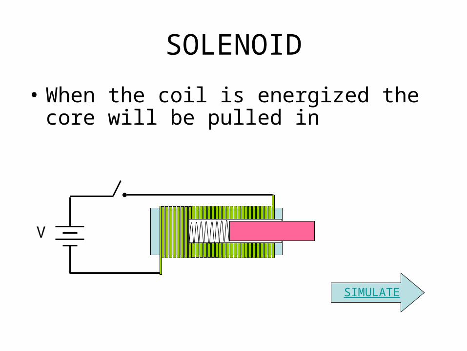
SOLENOID
• When the coil is energized the core will be pulled in
SOLENOID
corecoil
coil
core
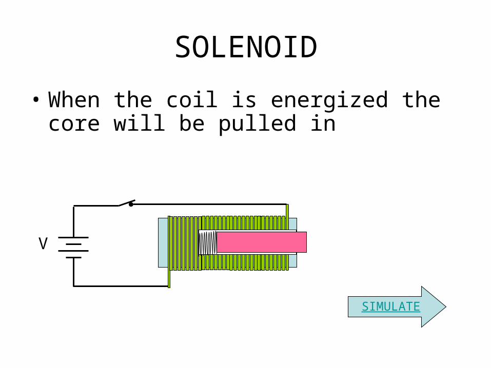
SOLENOID
• When the coil is energized the core will be pulled in
V
SIMULATE
SOLENOID
• When the coil is energized the core will be pulled in
V
SIMULATE
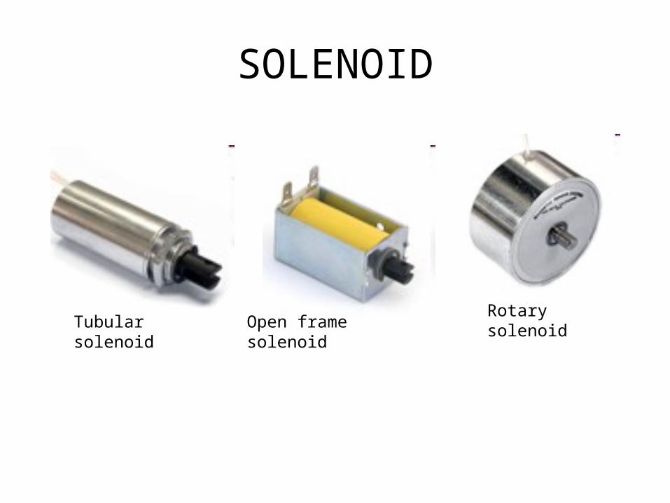
SOLENOID
Tubular solenoid Open frame solenoidRotary solenoid

Solenoid

Solenoid Usage
• pushing buttons,
• hitting keys on a piano,
• Open closed Valve,
• Heavy duty contactor
• jumping robots
• etc
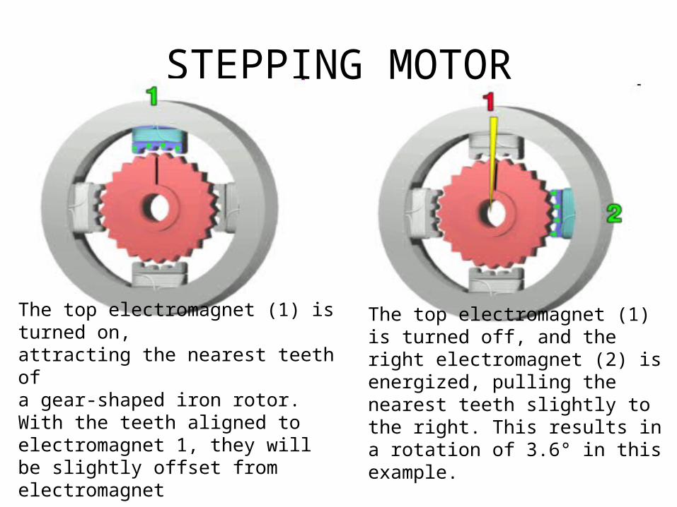
STEPPING MOTOR
The top electromagnet (1) is turned on, attracting the nearest teeth of a gear-shaped iron rotor. With the teeth aligned to electromagnet 1, they will be slightly offset from electromagnet
The top electromagnet (1) is turned off, and the right electromagnet (2) is energized, pulling the nearest teeth slightly to the right. This results in a rotation of 3.6° in this example.

STEPPING MOTOR
The bottom electromagnet (3) is energized; another 3.6° rotation occurs.
The left electromagnet (4) is enabled, rotating again by 3.6°.
When the top electromagnet (1) is again enabled, the teeth in the sprocket will have rotated by one tooth position; since there are 25 teeth, it will take 100 steps to make a full rotation in this example.

STEPPING MOTOR
• Practical stepping motor can be controlled for full step and half step.
• Common typical step size is 1.8o for full step and 0.90 for half step
• Full step is accomplished by energizing 2 adjacent electromagnet simultaneously.
• Half step is accomplished by energizing 1 electromagnet at a time.

Stepping motor
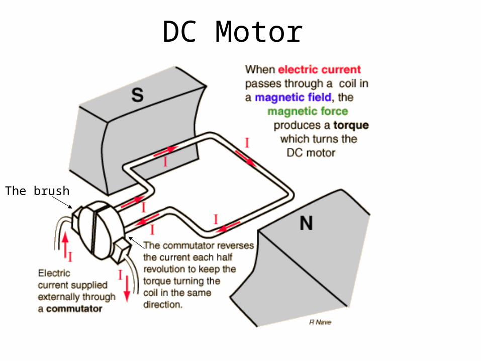
DC Motor
The brush
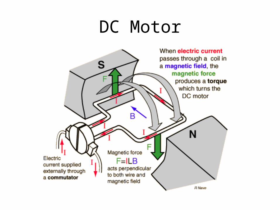
DC Motor
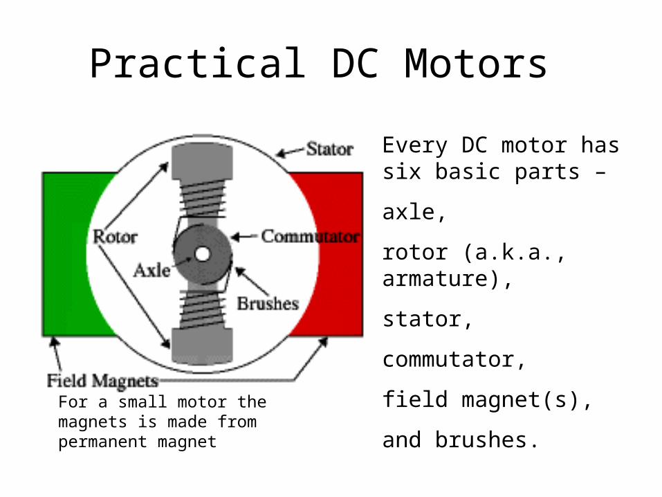
Practical DC Motors
Every DC motor has six basic parts –
axle,
rotor (a.k.a., armature),
stator,
commutator,
field magnet(s),
and brushes. For a small motor the magnets is made from permanent magnet

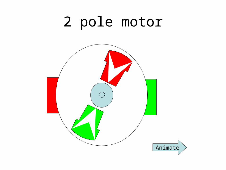
2 pole motor
Animate
2 pole motor
Animate

2 pole motor
Animate

2 pole motor
Animate

2 pole motor
Animate

2 pole motor
Animate

2 pole motor
Animate

2 pole motor
Animate

2 pole motor
Animate
continue

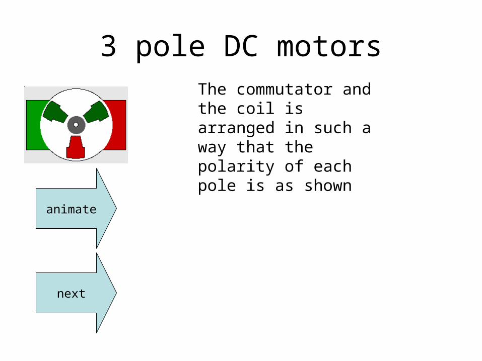
3 pole DC motors
+ −
The coil for each poles are connected serially.
The commutator consist of 3 sector, consequently one coil will be fully energized and the others will be partially energized.
1
3 2

3 pole DC motors
animate
next
The commutator and the coil is arranged in such a way that the polarity of each pole is as shown

3 pole DC motors
animate
next
The commutator and the coil is arranged in such a way that the polarity of each pole is as shown
animate
next
The commutator and the coil is arranged in such a way that the polarity of each pole is as shown
3 pole DC motors

animate
next
3 pole DC motorsThe commutator and the coil is arranged in such a way that the polarity of each pole is as shown

DC motors
• As the rotor is rotating, back emf (Ea) will be produced, the faster the rotor turn the higher Ea and the smaller Ia.
• The starting current of motors will be much higher then the rating current.
motorV Ea
Ia

DC motorsFor big motors the magnet is made from coil and core. The current flowing in the coil is called If and the current flowing in the armature is called Ia.
The armature winding and the field winding are connected to a common power supply
The armature winding and the field winding are often connected in series, parallel, or compound. The torque characteristic will be different for each connection.
The figure shows a parallel connection
Field winding Armature winding
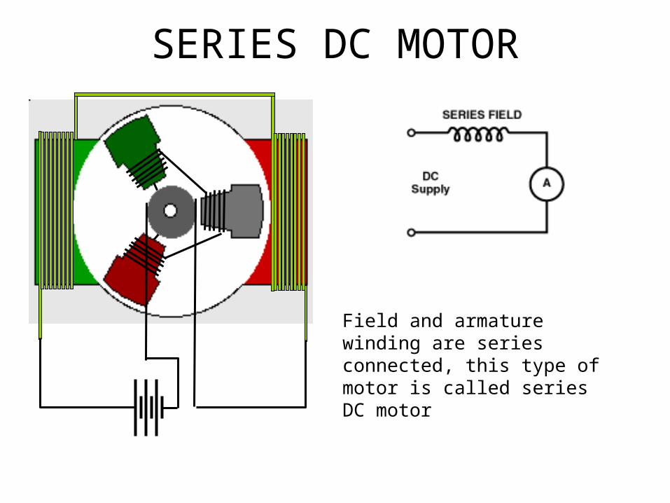
SERIES DC MOTOR
Field and armature winding are series connected, this type of motor is called series DC motor

DC motors
Field and armature winding are parallel connected, this type of motor is called shunt DC motor

DC MOTOR
Compound DC motor is DC motor having 2 field winding the first one is connected parallel to the armature winding and the other is connected series

DC MOTOR
Torque: T = KΦIa– K is a constant– Φ magnetic flux
– Ia is armature current
• Magnetic flux is constant if it is from permanent magnet
• It is depend on the If if it is produced by current

DC MOTOR TORQUE-SPEED CURVE
Torque: T = KΦIa

SERIES DC MOTOR TORQUE-SPEED CURVE
Torque:
T = KΦIa
T= KIa2

SHUNT DC MOTOR TORQUE-SPEED CURVE
Torque: T = KΦIa
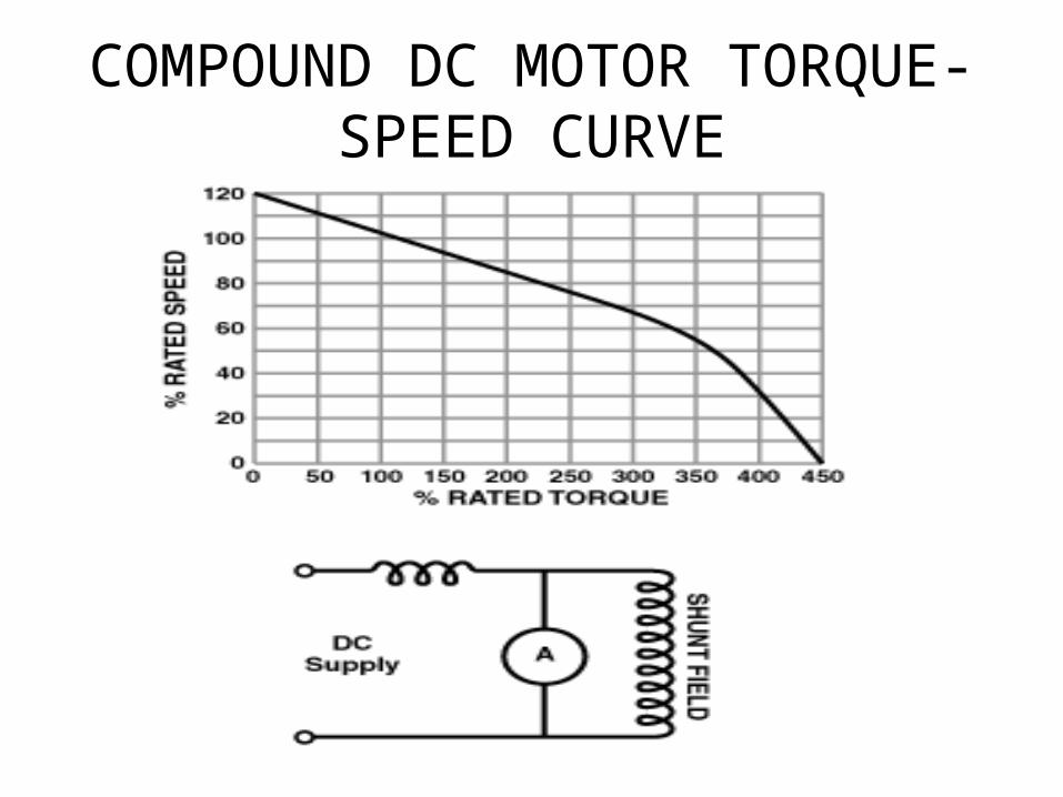
COMPOUND DC MOTOR TORQUE-SPEED CURVE

SYNCHRONOUS AC MOTORN
S
~
The rotating field.
When alternating current is applied to the field coil the magnetic field will also alternating. Therefore the permanent magnet will rotate
o
311-311

SYNCHRONOUS AC MOTORN
S
~
The rotating field.
When alternating current is applied to the field coil the magnetic field will also alternating. Therefore the permanent magnet will rotate
o
311-311

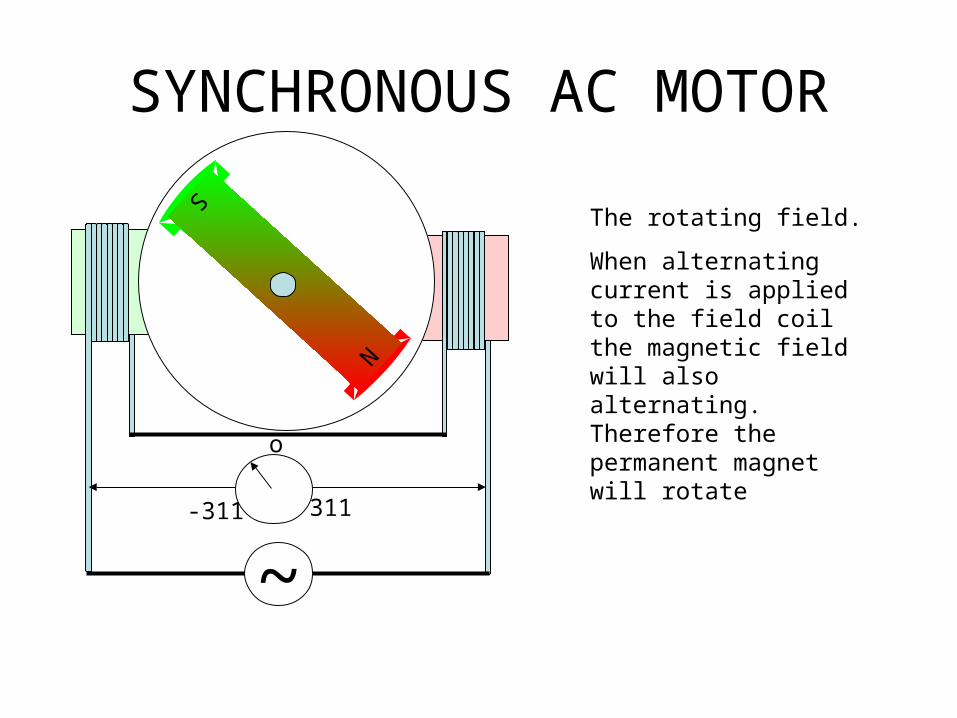
SYNCHRONOUS AC MOTOR
N
S
~
The rotating field.
When alternating current is applied to the field coil the magnetic field will also alternating. Therefore the permanent magnet will rotate
o
311-311

SYNCHRONOUS AC MOTOR
NS
~
The rotating field.
When alternating current is applied to the field coil the magnetic field will also alternating. Therefore the permanent magnet will rotate
o
311-311
SYNCHRONOUS AC MOTOR
N
S
~
The rotating field.
When alternating current is applied to the field coil the magnetic field will also alternating. Therefore the permanent magnet will rotate
o
311-311

SYNCHRONOUS AC MOTOR
N
S
~
The rotating field.
When alternating current is applied to the field coil the magnetic field will also alternating. Therefore the permanent magnet will rotate
o
311-311
SYNCHRONOUS AC MOTOR
N
S
~
o
311-311
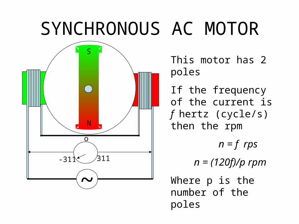
This motor has 2 poles
If the frequency of the current is f hertz (cycle/s) then the rpm
n = f rps
n = (120f)/p rpm
Where p is the number of the poles
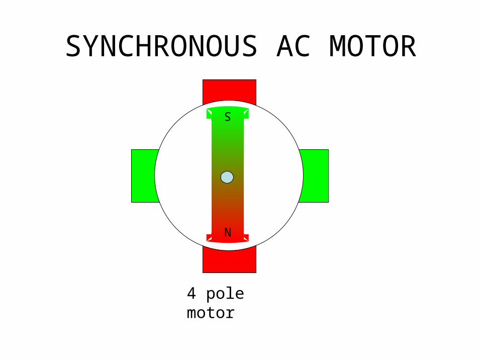
SYNCHRONOUS AC MOTOR
4 pole motor
N
S

THREE PHASE SYNCHRONOUS AC MOTOR
4 pole 3Φ motor
TSR
R S T
R S T
N
S

SYNCHRONOUS AC MOTOR

SYNCHRONOUS AC MOTOR USING EXTERNAL EXITER
R S T
The magnetic flux of permanent magnet is low for a bigger motor we have to use externally exited magnetic field

ASYNCHRONOUS AC MOTOR
Iinduced
• When instead of exited, the rotor coil is shorted an induced current will be generated and the rotor will be magnetized and start to turn.
• The faster the speed the smaller the induced current and finally the current will cease at synchronous speed and so does the rotation
• This motor will turn at speed less the its synchronous rotation that is why it called asynchronous motor
• This motor is also called induction motor

Calculating Motor Speed• A squirrel cage induction motor is a constant speed device. It cannot
operate for any length of time at speeds below those shown on the nameplate without danger of burning out.
• To Calculate the speed of a induction motor, apply this formula: Srpm = 120 x F
P Srpm = synchronous revolutions per minute.
120 = constantF = supply frequency (in cycles/sec)P = number of motor winding poles
• Example: What is the synchronous of a motor having 4 poles connected to a 60 hz power supply?
Srpm = 120 x F PSrpm = 120 x 60 4Srpm = 7200 4Srpm = 1800 rpm

Calculating Braking Torque
• Full-load motor torque is calculated to determine the required braking torque of a motor.To Determine braking torque of a motor, apply this formula:
T = 5252 x HP rpm
T = full-load motor torque (in lb-ft)5252 = constant (33,000 divided by 3.14 x 2 = 5252)HP = motor horsepowerrpm = speed of motor shaft
• Example: What is the braking torque of a 60 HP, 240V motor rotating at 1725 rpm?
T = 5252 x HP rpmT = 5252 x 60 1725T = 315,120 1725T = 182.7 lb-ft

Calculating Work• Work is applying a force over a distance. Force is any cause that
changes the position, motion, direction, or shape of an object. Work is done when a force overcomes a resistance. Resistance is any force that tends to hinder the movement of an object.If an applied force does not cause motion the no work is produced.
• To calculate the amount of work produced, apply this formula:• W = F x D• W = work (in lb-ft)
F = force (in lb)D = distance (in ft)
• Example: How much work is required to carry a 25 lb bag of groceries vertically from street level to the 4th floor of a building 30' above street level?
• W = F x DW = 25 x 30W = 750 -lb

Pneumatic Actuator

Pneumatic Actuator
Reverse-Acting Actuator


I/P Converter• A "current to pressure" converter (I/P) converts an analog
signal (4-20 mA) to a proportional linear pneumatic output (3-15 psig).
• Its purpose is to translate the analog output from a control system into a precise, repeatable pressure value to control pneumatic actuators/operators, pneumatic valves, dampers, vanes, etc.
I/PAir supply
30 psi
Current 4 to 20 mA
Pneumatic 3 to 15 psiSupplied to actuator

Sample of I/P Converter

Generation and distribution of pneumatic pressure
• Compressor is needed for pneumatic system
compressor
100 psi
PSPC
30 psi
Regulator valve
To I/P
Tank

Hydraulic Actuator
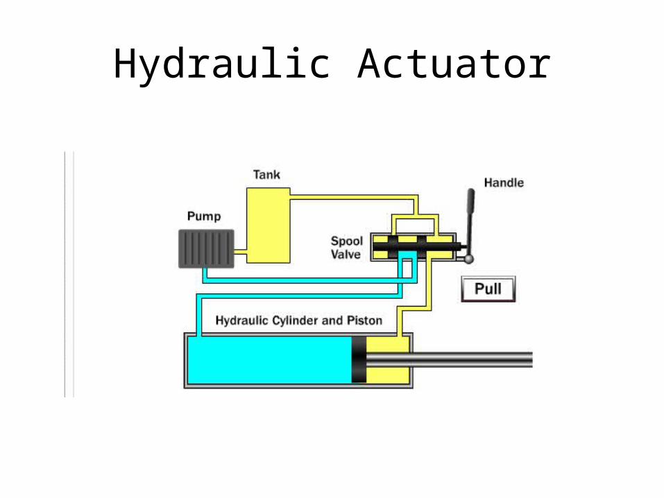
Hydraulic Actuator


Hydraulic Actuator
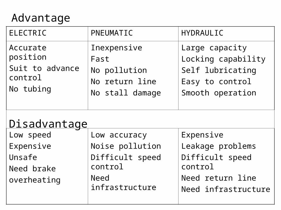
AdvantageELECTRIC PNEUMATIC HYDRAULIC
Accurate position
Suit to advance control
No tubing
Inexpensive
Fast
No pollution
No return line
No stall damage
Large capacity
Locking capability
Self lubricating
Easy to control
Smooth operation
Low speed
Expensive
Unsafe
Need brake
overheating
Low accuracy
Noise pollution
Difficult speed control
Need infrastructure
Expensive
Leakage problems
Difficult speed control
Need return line
Need infrastructure
Disadvantage


