Final Basis of Design Water - ScottsdaleAZ
11
Final Basis of Design Water FOR SCOTTSDALE COUNTRY INN & SUITES APN# 130-18-029 7316 (7312) E. Thomas Road Scottsdale, AZ 85251 City of Scottsdale Zoning Case # 16-ZN-2017 Case # 9-DR-2019, Rev 1 Submittal - July 10, 2019 Prepared for: GKI Architects 1823 E. Desert lane Phoenix, Arizona Prepared by: Mike Jackson, P.E. 1600 N Desert Drive, Suite 230 Tempe, AZ 85281 Phone: (480) 951-0517 Fax: (480) 951-2353 July 10, 2019 16-ZN-2017 7/10/2019 Revised July, 10 2019
Transcript of Final Basis of Design Water - ScottsdaleAZ
Final Basis of Design
Water
FOR
SCOTTSDALE COUNTRY INN & SUITES
APN# 130-18-029
7316 (7312) E. Thomas Road
Scottsdale, AZ 85251
City of Scottsdale Zoning Case # 16-ZN-2017
Case # 9-DR-2019, Rev 1
Submittal - July 10, 2019
Prepared for:
GKI Architects
1823 E. Desert lane
Phoenix, Arizona
Prepared by:
Mike Jackson, P.E.
1600 N Desert Drive, Suite 230
Tempe, AZ 85281
Phone: (480) 951-0517 Fax: (480) 951-2353
July 10, 2019
16-ZN-2017
7/10/2019
Revised July, 10 2019

1
TABLE OF CONTENTS
INTRODUCTION ........................................................................................................................... 2
EXISTING CONDITIONS .............................................................................................................. 2
PROPOSED CONDITIONS .......................................................................................................... 2
DESIGN CRITERIA ........................................................................................................................ 2
PROPOSED DESIGN FLOW........................................................................................................ 2
DOMESTIC METER SIZING .......................................................................................................... 2
HYDRAULIC ANALYSIS ............................................................................................................... 3
CONCLUSIONS ............................................................................................................................ 3
FIGURES
Figure 1: Utility Plan
Figure 2: Fire Flow Test
Figure 3: Fire Flow Calculations
7/10/2019
SCOTTSDALE COUNTRY INN & SUITES
9-DR-2019, REV 1
2
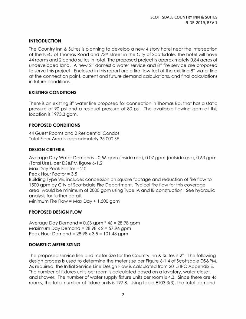
INTRODUCTION
The Country Inn & Suites is planning to develop a new 4 story hotel near the intersection
of the NEC of Thomas Road and 73rd Street in the City of Scottsdale. The hotel will have
44 rooms and 2 condo suites in total. The proposed project is approximately 0.84 acres of
undeveloped land. A new 2” domestic water service and 8” fire service are proposed
to serve this project. Enclosed in this report are a fire flow test of the existing 8” water line
at the connection point, current and future demand calculations, and final calculations
in future conditions.
EXISTING CONDITIONS
There is an existing 8” water line proposed for connection in Thomas Rd. that has a static
pressure of 90 psi and a residual pressure of 80 psi. The available flowing gpm at this
location is 1973.3 gpm.
PROPOSED CONDITIONS
44 Guest Rooms and 2 Residential Condos
Total Floor Area is approximately 35,000 SF.
DESIGN CRITERIA
Average Day Water Demands - 0.56 gpm (inside use), 0.07 gpm (outside use), 0.63 gpm
(Total Use), per DS&PM figure 6-1.2
Max Day Peak Factor = 2.0
Peak Hour Factor = 3.5
Building Type VB, includes concession on square footage and reduction of fire flow to
1500 gpm by City of Scottsdale Fire Department. Typical fire flow for this coverage
area, would be minimum of 2000 gpm using Type IA and IB construction. See hydraulic
analysis for further detail.
Minimum Fire Flow = Max Day + 1,500 gpm
PROPOSED DESIGN FLOW
Average Day Demand = 0.63 gpm * 46 = 28.98 gpm
Maximum Day Demand = 28.98 x 2 = 57.96 gpm
Peak Hour Demand = 28.98 x 3.5 = 101.43 gpm
DOMESTIC METER SIZING
The proposed service line and meter size for the Country Inn & Suites is 2”. The following
design process is used to determine the meter size per Figure 6-1.4 of Scottsdale DS&PM.
As required, the Initial Service Line Design Flow is calculated from 2015 IPC Appendix E.
The number of fixtures units per room is calculated based on a lavatory, water closet,
and shower. The number of water supply fixture units per room is 4.3. Since there are 46
rooms, the total number of fixture units is 197.8. Using table E103.3(3), the total demand

SCOTTSDALE COUNTRY INN & SUITES
9-DR-2019, REV 1
3
is 65 gpm. Based on the criteria in the DS&PM, add 10 gpm and multiply by 1.5 safety
factor. The final initial service line design flow is 112.5 gpm < 160 gpm as required.
HYDRAULIC ANALYSIS
The fire line calculations begin from the point where the static pressure was measured
and extend to the entrance of the building, then up to the farthest point of the sprinkler
system. The initial energy grade line at the starting point is de-rated to 72 psi (166.32 ft).
Friction, velocity, and elevation line losses are generated based on the sum of
maximum day plus fire flow demands for the building and height of the facility. Upon
entry into the building, a network of sprinklers are carried to the most distant point of the
building. Each sprinkler shall provide a minimum coverage of 200 SF. Estimating 15 gpm
per head, the total number of sprinklers is 175, with a demand of 2625gpm. To
calculate the head loss due to elevation difference, the height of the highest sprinkler
shall be 40 feet above finished floor. Refer to calculations in figure 3 for additional
calculations. The resultant pressure in the line calculated during operation is 36.78 psi.
CONCLUSIONS
The proposed project will provide for a new 2” water meter and domestic service and a
separate 8” fire line which will tie into the existing 8” water line in East Thomas Road. The
water lines in the Country Inn & Suites project will conform to the City of Scottsdale DS&PM
and 2015 IPC. Proposed water construction, materials, and appurtenances shall be per
DSPM, Chapters 6 & 7 and the City of Scottsdale Standard Detail Series 2300 and 2400.

Figure 1: Utility Plan

THOMAS ROAD
SD
SD
SD
SD
S
D
SS
S
WW
FF
=
12
34
.7
5
SD
SD
SD
SD
SD
S
D
GRAPHIC SCALE
LEGEND
W W
1600 N. DESERT DR
SUITE 230
TEMPE, AZ
85281
PH: 480.951.0517
www.imegcorp.com
Call at least two full working days
before you begin excavation.
Dial 8-1-1 or 1-800-STAKE-IT (782-5348)
In Maricopa County: (602) 263-1100
Arizona Blue Stake, Inc.
1
PR
EL
IM
IN
AR
Y G
RA
DIN
G P
LA
N
CO
UN
TR
Y IN
N &
S
UIT
ES
C1
IMEG CORP.
CIVIL ENGINEER ARCHITECT
GERALD KESLER
GKI ARCHITECTS
OWNER/DEVELOPER
KRISTA R CORPORATION
SITE DATA BENCHMARK
BASIS OF BEARING
VICINITY MAP
THIS PROJECT
BASIN 1
CB-1
STORMWATER MAINTENANCE PLAN
–
ENGINEER'S FEMA CERTIFICATION
DRAINAGE STATEMENT
UNDERGROUND STORAGE (UG-1) DETAIL
RETENTION VOLUMES
UG-1
DRYWELL
7/10/2019
CB-2
RETENTION PROVIDED
DRYWELL DISCHARGE
UTILITY NOTES
FW
S S

SCOTTSDALE COUNTRY INN & SUITES
9-DR-2019, REV 1
Figure 2: Fire Flow Test

DIA
DIA
DIA
5/11/2018
SIGNED: DATE:
AVAIL FLOW @ 20 PSI:
GPM
TOTAL GPM DURING TEST: 1973.3
11-May-18
5649.3
HYD # 1
C VAL
HYDRANT READINGS: DATE TAKEN: TIME:
2 PITOT 36 GPM
GPM 0.0
PROJECT #:
1973.3
ADDITIONAL INFO
HYD # 1 STATIC 90
THOMAS ROAD FLOW TESTADDRESS:
HYD # PITOT
CITY/ST/ZIP:
3.5 C VAL 0.9
CONTACT :
PHONE:
FAX:
MOBIL:
FRED GRAVES(480) 921-4393(480) 894-8740
7:00 AMRESIDUAL 80
DATE NEEDED:
TEMPE, AZ 85282
0.0
ENGINEERED FIRE SOLUTIONS, INC.1220 WEST GENEVA DRIVE
HYD #
ENGINEERED FIRE SOLUTIONS, INC. FLOW TEST SUMMARY SHEET
This flow test data is taken with pressure gauges which are calibrated for accuracy annually. We warrant that the results given are accurate for the time and date noted. We do not guarantee the results beyond this time due to daily or seasonal use, or water system changes. Careful consideration should be given to these issues when utilizing this information.
REQUESTOR:
ADDRESS:
C VAL
HYD # PITOT
7316 E. THOMAS RDScottsdale, AZ 85251
187022PROJECT NAME:
CITY/ST/ZIP:

0
10
20
30
40
50
60
70
80
90
100
0 500 1000 1500 2000 2500 3000 3500 4000 4500 5000 5500 6000 6500 7000
Pres
sure
(p
si)
Flow (gpm)
Flow Test Water Supply Curve

SCOTTSDALE COUNTRY INN & SUITES
9-DR-2019, REV 1
Figure 3: Fire Flow Calculations

PIPING HYDRAULIC ANALYSIS & HYDRAULIC PROFILE (Smooth Pipe Only)
Project Name: Scottsdale Hotel
Project No:
PIPING I.D. No.
Date of this Run: 10-Jul-19 Straight pipe 0
Time: 10:55 AM
FITTINGS K*
Darcy Weisbach Friction factor: (see note below) Entrance 1 0.5
Exit 2 1
f=10x, Where x = [-1.4655-0.2775*log 10VD 90 deg. bend 3 0.3
+0.0340*(log10VD)2-0.0029*(log10VD)
3] 45 deg. bend 4 0.2
Where V=velocity in ft/sec & Tee - thru run 5 0.3
D=Pipe dia in inches Tee - thru branch 6 0.9
Valve 7 0.27
Starting EGL = 166.32 Check valve 8 1.5
Reducer 200.5(1-sd2/ld
2) sd = small dia.;
Ending EGL = Enlargement 30(1-sd2/ld
2)2
ld = large dia.
Approx loss of 10psi in double check not modeled * from "Cameron", 16th Edition
Piping Size Length Elev. Q V f Hv Hf Pressure Head
Loc. I.D. No. in. ft. ft. gpm fps (D-W) ft. ft. HGL EGL feet psi
L1 1 8 1.00 2683 17.13 0.0117 4.554 2.277 159.49 164.04 158.49 68.67
L2 0 8 170 1.00 2683 17.13 0.0117 4.554 13.596 145.89 150.45 144.89 62.78
L3 3 8 1.00 2683 17.13 0.0117 4.554 1.366 144.53 149.08 143.53 62.19
L4 0 8 39 1.00 2683 17.13 0.0117 4.554 3.119 141.41 145.96 140.41 60.84
L5 3 8 1.00 2683 17.13 0.0117 4.554 1.366 140.04 144.60 139.04 60.24
L6 0 8 40 41.00 2683 17.13 0.0117 4.554 3.199 136.84 141.40 95.84 41.53
L7 3 8 41.00 2683 17.13 0.0117 4.554 1.366 135.48 140.03 94.48 40.93
L8 0 8 120 41.00 2683 17.13 0.0117 4.554 9.597 125.88 130.43 84.88 36.78
L9
L10
L11
L12
L13
L14
L15
L16
L17
L18
L19
L20
L21
L22
L23
L24
L25
L26
L27
Note: the friction factor formula was derived using Excel's curve fitting capabilities based upon a table derived
from the Moody Diagram (log-log) for smooth pipes.
17001603.00
Print Date / Time: 7/10/2019, 10:55 AM File: f\Fire Line Loss Calculation REV1.xls Page 1 of 1