FINAL 07.20.2015 CITY OF SAN RAFAEL - storage.googleapis.com · San Rafael Strategic Plan Tier 1 -...
120
Prepared by: ESSENTIAL FACILITIES STRATEGIC PLAN DETAILED FACILITY STUDY Public Safety Center VOLUME II FINAL 07.20.2015 CITY OF SAN RAFAEL
Transcript of FINAL 07.20.2015 CITY OF SAN RAFAEL - storage.googleapis.com · San Rafael Strategic Plan Tier 1 -...

Prepared by:
ESSENTIAL FACILITIESSTRATEGIC PLAN
DETAILED FACILITY STUDY
Public Safety CenterVOLUME II
FINAL 07.20.2015
CITY OFSAN RAFAEL

CITY OF SAN RAFAELESSENTIAL FACILITIES STRATEGIC PLAN
A. INTRODUCTION -------------------------------------------------------------- II-1 - II-2
B. PUBLIC SAFETY CENTER PROGRAMOVERALL SPACE NEEDS SUMMARY AND SUMMARY OF BUILDING PER DEPARTMENT ------------------------------------------------------ II-3 - II-5SPACE NEEDS OUTLINE ------------------------------------------------------------- II-6 - II-32SPACE STANDARDS AND COMPONENT DIAGRAMS ---------------------------- II-33 - II-54 OVERALL PROJECT BUDGET -------------------------------------------------------- II-55 - II-57SITE ARRANGEMENT DIAGRAMS -------------------------------------------------- II-58 - II-60
C. EXISTING FACILITY ASSESSMENTSSTATION 51 – 1039 C STREET ------------------------------------------------------ II-61 - II-62CITY HALL – 1400 5TH AVENUE ----------------------------------------------------- II-63
APPENDIXSan Rafael Strategic Plan Tier 1 - Fire Station No. 51Structural Review and Conditional Assessment Prepared by Cornerstone Structural Engineering GroupDated: June 23, 2015
Basis of Design Narrative - Fire Station 51City of San Rafael - Essential Facilities Strategic PlanMEP Review and Conditional Assessment Prepared by Interface EngineeringDated: June 22, 2015
TABLE OF CONTENTS
VOLUME II. DETAILED FACILITY STUDY - PUBLIC SAFETY CENTER
FINAL 7/20/15
PAGE NO.


FINAL 7/20/15 CITY OF SAN RAFAELESSENTIAL FACILITIES STRATEGIC PLAN
DRAFT CITY OF SAN RAFAEL JUNE X. 2015 ESSENTIAL FACILITIES STRATEGIC PLAN
II‐0 | A – Introduction
VOLUME II. DETAILED FACILITY STUDY – PUBLIC SAFETY CENTER
A. INTRODUCTION
Initially, Space Needs Assessments were developed for a stand‐alone police station and a replacement “Headquarters Fire Station” which comprised of Fire Station 51, Fire Administration functions and a new Emergency Operations Center. The police station and the headquarters fire station were each envisioned to be placed on separate sites. The replacement headquarters fire station was evaluated on a site near 2nd street and the police station was studied to be either added to City Hall or replaced across the street from City Hall on 5th Avenue. As the scenario study developed, it became apparent that these two stand‐alone projects did not develop into a cost‐effective solution for improving the seismic safety and operations of each department. It was determined that in order to maximize the funds available the following considerations would need to be made:
A joint Public Safety Center would allow many of the spatial elements of a police and fire station to be shared. They include the lobby, public restrooms, staff break and restrooms, classroom, and all circulation and mechanical/electrical support spaces.
If at all possible, the replacement facilities should be located on City‐owned property. This would allow the maximum amount of available funds to be put toward facility improvements instead of property purchases.
Evaluate alternative possibilities for moving Medic 51 closer to the freeway as a response to the recommendations of the Standards of Coverage Study in place of re‐building space in a potential Public Safety Center (PSC) at its similar location (discussed in Volume I).
Mission critical for both the San Rafael Fire and Police Departments (SRFD and SRPD) is to have all divisions located in the same building and moved from the leased spaces they currently occupy.
Concurrent with developing the Space Need Assessments for each department, the Design Team evaluated the existing facilities currently serving each group. The goal was to determine if the facilities could be cost‐effectively renovated to serve the established needs and goals of providing operationally efficient and seismically safe facilities for each department. The Team evaluated the existing Fire Station 51 and the existing City Hall (SRPD is located in the first level of City Hall). In general, it was determined that neither renovating and adding to the existing City Hall, nor renovating and expanding the existing Fire Station 51 proved to be cost‐effective or operationally efficient solutions to meeting the stated goals above. The detail behind these findings is presented in Section C of this report.
The proposed Public Safety Center (PSC), detailed in the following documents, recommends the development of a 44,666‐square‐foot PSC, located on City‐owned property on 5th Avenue between C and D Streets.
PUBLIC SAFETY CENTER AT 1401 5TH AVENUE: $41M – $43M PROJECT BUDGET (INCLUDING RENTAL SAVINGS)
The following Overall Space Needs Summary, Space Standards and Component Diagrams, Site Arrangement Diagrams, and Overall Conceptual Project Budget provide the background detail which resulted in the proposed total square footage recommendation and overall project budget range. These documents will be used in the
A – Introduction | II-1

FINAL 7/20/15CITY OF SAN RAFAELESSENTIAL FACILITIES STRATEGIC PLANCITY OF SAN RAFAEL DRAFT ESSENTIAL FACILITIES STRATEGIC PLAN JUNE X. 2015
A – Introduction | II‐1
subsequent phases of the Measure E, Essential Facility Improvement Program as a basis for design and budget confirmation.
FACILITY OVERVIEW
San Rafael Police Department (SRPD) features include: Adequate on‐site storage area to eliminate off‐site storage costs. Locates all SRPD units in the same building except the Youth Services Bureau and the Marine Unit. SRPD program provides 424 net square feet to accommodate future staffing levels including:
- One new Street Crimes Officer – 24 SF work station - One new Motor Officer – 24 SF work station - One property and evidence assistant – 80 SF work station - One new investigator – 80 SF work station - Three additional records specialists – 216 SF
San Rafael Fire Department (SRFD) features include: Adequate on‐site storage area to eliminate off‐site storage costs. A fire department administrative program which provides 264 net square feet to accommodate future staffing
levels including: - One new Fire Administrator – 120 SF office - One new Public Education Specialist – 72 SF work station - One new Emergency Medical Service (EMS) Clerk – 72 SF work station
An Emergency Operations Center that includes seating for 60 and training at tables for 24 with support areas for the emergency management functions.
The Fire Engine 51 Company with apparatus bay space for cross‐staffing a ladder truck and a secure bay for the BC vehicle. It provides living accommodations for four fire fighters and the BC.
Joint Facilities include: Conference rooms Emergency Operations Center (EOC)/training room Break rooms Fitness room Lobby and public restrooms Men’s and women’s staff toilets All Infrastructure support areas including computer rooms, electrical rooms, etc.
Items and functions not included which will need to be accommodated at another location: Parking – only patrol vehicles and specialized support units (SWAT, CSI VAN, and various trailers) are planned
to be on‐site. Personal vehicles and un‐marked SRPD vehicles will be parked off‐site. The SRFD Apparatus Maintenance Program will be relocated to the Public Works Yard. Medic Unit 51 will be relocated to Fire Station 52. The Youth Services Bureau may be relocated to the first floor of the current City Hall.
II-2 | A – Introduction

CITY OF SAN RAFAELESSENTIAL FACILITIES STRATEGIC PLAN
OVERALL SPACE NEEDS SUMMARY AND SUMMARY OF BUILDING PER DEPARTMENT
B. PUBLIC SAFETY CENTER PROGRAM
The Space Needs Summary summarizes the anticipated building space needs into an outline form indicating each departments area requirements and the building support areas. The summary of space needs per department lists the anticipated space needs per department and provides a breakdown of the shared and non-shared space allocations.


B – Public Safety Center Program | II-3
OVERALL SPACE NEEDS SUMMARY AND SUMMARY OF BUILDING PER DEPARTMENT
COMBINED PD/FD - PUBLIC SAFETY CENTEROVERALL SPACE NEEDS SUMMARY
Component 2015 2040 Comment
Area Gross S.F.
Number of Personnel
Area Gross S.F.
Number of Personnel
Office of the Police Chief 655 3.0 655 3.0Fire Administration 2,200 14.0 2,387 17.0 Includes Fire
AdministratorEmergency Operations Center 2,079 1.0 2,079 1.0 Includes Large
Training/EOC RoomOperations Division: Office 562 42.0 562 51.0 Includes Operations
Captain OfficeStreet Crimes 580 3.0 611 4.0Patrol Sergeant Work Room 867 867 Staff counted in
Operations: OfficeTraffic 395 3.0 426 4.0Misc. Functional Spaces 125 6.0 125 7.0 Foot BeatCadets 248 6.0 248 6.0
Patrol Support Areas 2,284 2,284 Staff counted in Operations: Office
Evidence Processing and Secure Storage
2,509 1.0 2,509 2.0
Temporary Holding 2,698 2,698Investigations 3,414 11.0 3,518 12.0 Includes Admin.
Captain OfficeProfessional Standards 738 3 738 3Youth Services Bureau 0 5 0 5 Location TBDRecords 1,877 6 2,157 9Dispatch 996 10 1,017 12Staff Support 5,388 5,388Facility Support 5,811 5,811 Size based on 2040
staffingStation 51 Apparatus Bay and Support 3,931 3,931Station 51 Offices 635 635Station 51 Living Quarters 1,959 1,959
Total Building Spaces 39,950 111.0 40,605 133.0Building Gross Factor - 10% 3,995 4,061
Total Building Gross Square Footage 43,945 44,666

II-4 | B – Public Safety Center Program
Ancillary Support - On-Site 1,771 1,771 Motors, Bicycles, Large Vehicle Storage. Store in Sub-Terrain Garage Area. Minimum improvements.
Exterior Spaces - Some parking level, Some at street level.
13,386 13,386
Total Exterior and Building Spaces 59,102 59,823
Ancillary Support - Parking Level 6,191 6,191 Trailers and vehicles
Component 2015 2040 Comment
Area Gross S.F.
Number of Personnel
Area Gross S.F.
Number of Personnel
OVERALL SPACE NEEDS SUMMARY AND SUMMARY OF BUILDING PER DEPARTMENT

B – Public Safety Center Program | II-5
SUMMARY OF BUILDING SPACE PER DEPARTMENTFD PD Share
Area Gross S.F.
Area Gross S.F.
Area Gross S.F.
Office of the Police Chief 655
Fire Administration 2,387
Emergency Operations Center 2,079
Operations Division: Office 562
Street Crimes 611
Patrol Sergeant Work Room 867
Traffic 426
Misc. Functional Spaces 125
Cadets 248
Patrol Support Areas 2,284
Evidence Processing and Secure Storage 2,509
Temporary Holding 2,698
Investigations 3,518
Professional Standards 738
Youth Services Bureau 0
Records 2,157
Dispatch 1,017
Staff Support 5,388 Shared 50/50
Facility Support 5,811
Station 51 Apparatus Bay and Support 3,931
Station 51 Offices 635
Station 51 Living Quarters 1,959
Total Building Spaces 10,990 18,416 11,199
Building Gross Factor - 10% 1,099 1,842 1,120
Total Building Gross Square Footage 12,089 20,257 12,319 44,666
Area percentage per Work Group: 27.07% 45.35% 27.58%
OVERALL SPACE NEEDS SUMMARY AND SUMMARY OF BUILDING PER DEPARTMENT


CITY OF SAN RAFAELESSENTIAL FACILITIES STRATEGIC PLAN
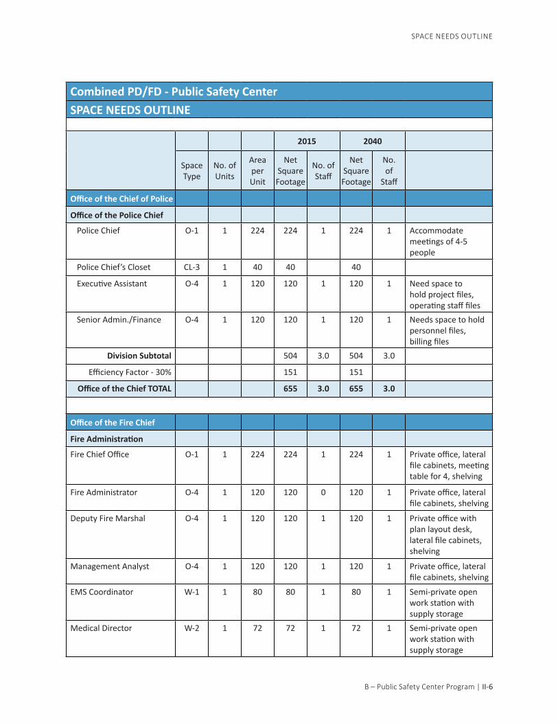
SPACE NEEDS OUTLINE
This section identified and itemizes the building spaces into an outline form indicating each space, the required attributes and the required square footage. The space needs of the project have been established through meet-ings with both the police department and fire department design team, site visits and multiple review meetings. The square footage requirements for each space are derived through the development of “component dia-grams” reflecting the operations-based layout of each space and the use of space standards
B. PUBLIC SAFETY CENTER PROGRAM

B – Public Safety Center Program | II-6
Combined PD/FD - Public Safety CenterSPACE NEEDS OUTLINE
2015 2040
Space Type
No. of Units
Area per Unit
Net Square Footage
No. of Staff
Net Square Footage
No. of
Staff
Office of the Chief of Police
Office of the Police Chief
Police Chief O-1 1 224 224 1 224 1 Accommodate meetings of 4-5 people
Police Chief’s Closet CL-3 1 40 40 40
Executive Assistant O-4 1 120 120 1 120 1 Need space to hold project files, operating staff files
Senior Admin./Finance O-4 1 120 120 1 120 1 Needs space to hold personnel files, billing files
Division Subtotal 504 3.0 504 3.0
Efficiency Factor - 30% 151 151
Office of the Chief TOTAL 655 3.0 655 3.0
Office of the Fire Chief
Fire Administration
Fire Chief Office O-1 1 224 224 1 224 1 Private office, lateral file cabinets, meeting table for 4, shelving
Fire Administrator O-4 1 120 120 0 120 1 Private office, lateral file cabinets, shelving
Deputy Fire Marshal O-4 1 120 120 1 120 1 Private office with plan layout desk, lateral file cabinets, shelving
Management Analyst O-4 1 120 120 1 120 1 Private office, lateral file cabinets, shelving
EMS Coordinator W-1 1 80 80 1 80 1 Semi-private open work station with supply storage
Medical Director W-2 1 72 72 1 72 1 Semi-private open work station with supply storage
SPACE NEEDS OUTLINE

II-7 | B – Public Safety Center Program
Nurse Educator W-2 1 72 72 1 72 1 Semi-private open work station with supply storage
Administrative Open Work Area (Two positions)
W-2 2 72 144 2 144 2 Open work stations adjacent to lobby, lateral file cabinets, shelving, adjacent to copy, file, supply room
EMS Open Work Area (Two Current Positions, One Future)
W-2 2 72 144 2 216 3 Open work stations adjacent to Admin-istrative Work Area, one - “Times-two, 7 tier” file cabinet in open work area, shelving, adjacent to copy, file, supply room
Fire Prevention Open Work Area Fire Inspector II (Two Positions)
W-1 2 80 160 2 160 2 Open Work Area adjacent to Fire Marshall ; two work stations and work counter for plan layout, storage area for inactive files and plans; near Admin. Work area.
Vegetation Management Specialist
W-2 1 72 72 1 72 1 Open work station, lateral file cabinets, shelving
Environmental Management Coordinator
W-2 1 72 72 1 72 1 Open work station, lateral file cabinets, shelving
Future Public Education Specialist Office/Storage
W-2 1 72 0 0 72 1 Open work station, desk, files, shelving, adjacent to storage room.
Fire General Storage - Supply
CL-5 1 60 60 60 Full-height shelving. Public Ed. And Medical Supply Storage
Fire Administration - Continued
SPACE NEEDS OUTLINE
2015 2040
Space Type
No. of Units
Area per Unit
Net Square Footage
No. of Staff
Net Square Footage
No. of
Staff

B – Public Safety Center Program | II-8
Fire Admin File Storage F-4 7 16 112 112 File cabinets (locking); 4 - “Times-Two” - 7 tier file systems
Fire Admin Workroom/Storage
F-3 3 40 120 120 Full-height shelving, open area for copy machine, central work counter for report assembly, storage for office supplies, form storage, mail box for each station and admin. personnel
Division Subtotal 1,692 14.0 1,836.0 17.0
Efficiency Factor - 30% 508 551
Fire Administration TOTAL 2,200 14.0 2,387 17.0
Emergency Operations Center
Main Response Room C-4 1 960 960 960 Seating for 60; storage areas; counters; serves as EOC room and class-room, partition
Call Taker Room, Ham Radio C-1 1 180 180 180 4 work stationsEquipment Storage CL-5 3.25 60 195 195 Table and Chair
storage, rations, cots, equipment
Task Force Conference Rm. (two total)
O-4 0 120 0 0 Removed from Program - Use Conference Rooms adjacent to lobby in major event
EOC Coordinator O-4 1 120 120 1 120 1 Private office, lateral file cabinets, shelving
SPACE NEEDS OUTLINE
Fire Administration - Continued
2015 2040
Space Type
No. of Units
Area per Unit
Net Square Footage
No. of Staff
Net Square Footage
No. of
Staff

II-9 | B – Public Safety Center Program
Wall Map W-2 2 72 144 0 144 ROSS mapping, maps, TV monitors, CAD monitors
Division Subtotal 1,599.0 1.0 1,599.0 1.0Efficiency Factor - 30% 480 480
Emergency Operations Center TOTAL
2,079 1.0 2,079 1.0
Operations Division
Operations Division: Office
Operations Captain O-3 1 132 132 1 132 1
Operations Captain’s Closet
CL-3 0.5 40 20 20
Day Shift
Day Shift Police Lieutenant
O-4 1 120 120 1 120 1 Shared office with Night Shift Lieutenant
Lieutenant’s Closet CL-3 0.5 40 20 20
Patrol Team 1 Sergeant 1 1 Refer to Patrol Sergeant shared office space
Patrol Team 1 8 10
Patrol Team 2 Sergeant 1 1 Refer to Patrol Sergeant shared office space
Patrol Team 2 9 10
Night Shift
Night Shift Police Lieutenant
O-4 1 120 120 1 120 1 Shared office with Day Shift Lieutenant
Lieutenant’s Closet CL-3 0.5 40 20 20
2015 2040
Space Type
No. of Units
Area per Unit
Net Square Footage
No. of Staff
Net Square Footage
No. of
Staff
SPACE NEEDS OUTLINE
Emergency Operations- Continued

B – Public Safety Center Program | II-10
Patrol Team 3 Sergeant 1 1 Refer to Patrol Sergeant shared office space
Patrol Team 3 9 10
Patrol Team 4 Sergeant 1 1 Refer to Patrol Sergeant shared office space
Patrol Team 4 9 10
Future CSO
CSO 0 4
Division Subtotal 432 432
Efficiency Factor - 30% 130 130
Operations Division Office TOTAL
562 42.0 562 51.0
Street Crimes
Street Crimes Sergeant W-1 1 80 80 1 80 1 Street Crimes Sergeant office would be in Street Crimes work area, Adjacent to Patrol
Street Crimes Officers
Street Crimes Work Area
Workstations W-4 1 24 48 2 72 3
Case Files F-1 8 5 40 40
Equipment Storage CL-1 3 8 24 24 Raid jackets, vests, thigh holsters, trackers, wires, locked.
Work Table F-3 4 40 160 160 Table for 4- 6 with white board and covered bulletin board, away from the entry
Book shelves SH-1 1 40 40 40
File Cabinets F-1 3 5 15 15
SPACE NEEDS OUTLINE
Night Shift - Continued
2015 2040
Space Type
No. of Units
Area per Unit
Net Square Footage
No. of Staff
Net Square Footage
No. of
Staff

II-11 | B – Public Safety Center Program
K-9 Support
Workstation W-3 0 48 Staffed by Street Crimes Unit
Files F-2 1 13.5 14 14
Case Law Books SH-4 1 12 12 12
Equipment Cabinet F-2 1 13.5 14 14
Kennels See Ancillary Police Support space list
Division Subtotal 446 470
Efficiency Factor - 30% 134 141
Street Crimes TOTAL 580 3.0 611 4.0
Patrol Sergeant Work Room
Sergeant Work Area Workstations W-2 6 72 432 432 Four Patrol Team
Sergeants and Foot Beat Sergeant, One Light duty. Refer to Unit for Staffing
Color Printer/Copier F-3 1 40 40 40 File Storage F-1 6 5 30 30 Forms Storage F-1 1 5 5 5 Resource Manuals SH-4 1 12 12 12 Briefing Table B-1 6 18 108 108 Equipment Storage
CL-1 5 8 40 40
Division Subtotal 667 667Efficiency Factor - 30% 200 200
Patrol Sergeant Work Room TOTAL
867 0.0 867 0.0
2015 2040
Space Type
No. of Units
Area per Unit
Net Square Footage
No. of Staff
Net Square Footage
No. of
Staff
SPACE NEEDS OUTLINE
Operations Division- Continued
B – Public Safety Center Program | II-12
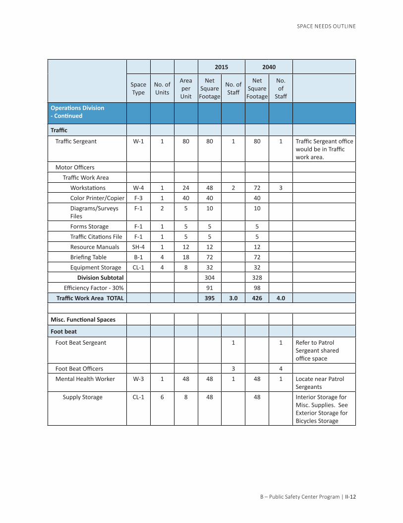
Traffic
Traffic Sergeant W-1 1 80 80 1 80 1 Traffic Sergeant office would be in Traffic work area.
Motor Officers Traffic Work Area Workstations W-4 1 24 48 2 72 3 Color Printer/Copier F-3 1 40 40 40 Diagrams/Surveys Files
F-1 2 5 10 10
Forms Storage F-1 1 5 5 5 Traffic Citations File F-1 1 5 5 5 Resource Manuals SH-4 1 12 12 12 Briefing Table B-1 4 18 72 72 Equipment Storage CL-1 4 8 32 32
Division Subtotal 304 328Efficiency Factor - 30% 91 98
Traffic Work Area TOTAL 395 3.0 426 4.0
Misc. Functional Spaces
Foot beat
Foot Beat Sergeant 1 1 Refer to Patrol Sergeant shared office space
Foot Beat Officers 3 4 Mental Health Worker W-3 1 48 48 1 48 1 Locate near Patrol
Sergeants Supply Storage CL-1 6 8 48 48 Interior Storage for
Misc. Supplies. See Exterior Storage for Bicycles Storage
SPACE NEEDS OUTLINE
2015 2040
Space Type
No. of Units
Area per Unit
Net Square Footage
No. of Staff
Net Square Footage
No. of
Staff
Operations Division- Continued

II-13 | B – Public Safety Center Program
Marine
Officer W-3 0 48 0 1 0 1 Located Off-site Supply Storage CL-3 0 40 0 0 See Off-site Storage
for additional supplies
Division Subtotal 96 96Efficiency Factor - 30% 29 29
Misc. Functional Spaces TOTAL
125 6.0 125 7.0
Cadets
Cadet Work Area 6 6 Overseen by Traffic Sergeant, locate near patrol
Workstations W-3 2 48 96 96
Work Bench F-3 1 40 40 40
Equipment Storage F-1 3 5 15 15
Book Case SH-4 2 12 24 24
1 16 16 16
Division Subtotal 191 191
Efficiency Factor - 30% 57 57
Cadet Work Area TOTAL 248 6.0 248 6.0
Volunteers
Volunteer work station 18 total Volunteer - Not counting in staffing. Refer to Investigations and Records for work station locations
2015 2040
Space Type
No. of Units
Area per Unit
Net Square Footage
No. of Staff
Net Square Footage
No. of
Staff
SPACE NEEDS OUTLINE

B – Public Safety Center Program | II-14
Operations Division: Support Functions
Patrol Support Areas
Briefing Room
Seating B-1 20 18 360 360 reduced from 24 to 20
Presentation Area 1 40 40 40
Duty Bag Room
Duty Bag/2nd Bag Room L-3 67 2.75 184.25 184 2 per sworn field ops personnel, 74 total Sworn. Less 7 Admin. 67 total storage lockers
Patrol Equipment CL-4 2 40 80 80 Flashlight, Radios, Cameras, Keys, Gloves, Wipes
Equipment Room
Patrol Equipment 1 120 120 120 Rifles, shotguns, ammo, handcuffs, vests
SWAT Equipment 1 120 120 120 SWAT Specialty rifles, Rams, ammo.
Armory
Ammunition SH-1 2 40 80 80 16’ of full height shelving
Gun cleaning station F-3 1 40 40 40 Workbench with air tools, parts storage
Shotgun Storage SH-2 3 56 168 168 24’ of full height shelving - 4’ deep
Training guns and supplies SH-2 1 56 56 56 16’ of full height shelving - 4’ deep
Gun Clearing Station 2 9 18 18
Report Writing Room
Report Writing Stations W-4 8 24 192 192 Includes two special program stations
Form Storage F-1 2 5 10 10
Officer Files F-2 4 13.5 54 54 4 - 4-drawer high cabinets
SPACE NEEDS OUTLINE
2015 2040
Space Type
No. of Units
Area per Unit
Net Square Footage
No. of Staff
Net Square Footage
No. of
Staff

II-15 | B – Public Safety Center Program
Juvenile Holding
Holding Room I-3 1 100 100 100 Visual contact to report writing
Work Area F-3 3 40 120 120 printer/copier, office supply storage, counter for report assembly, fax
Officer Mail Boxes 60 0.25 15 15 1 per sworn field ops personnel
Division Subtotal 1,757 1,757
Efficiency Factor - 30% 527 527
Patrol Support Work Area TOTAL
2,284 0.0 2,284 0.0
Evidence Processing and Secure Storage
Evidence Processing 1 250 250 250 Perimeter counter space with sink. Center island for evidence layout, fingerprint testing , weighing, photographing, (2 drying cabinets, 2 fume hoods), CSI supplies storage
Bag and Tag work area 1 60 60 60 Evidence processing supplies
Valtox Work area 1 60 60 60 Kit storage and workbench
Temporary Storage Lockers 1 60 60 60 Temporary storage while processing
Refrigerator/Freezer 1 18 18 18 Temporary storage while processing
SPACE NEEDS OUTLINE
Patrol Support Areas - Continued
2015 2040
Space Type
No. of Units
Area per Unit
Net Square Footage
No. of Staff
Net Square Footage
No. of
Staff

B – Public Safety Center Program | II-16
Property and Evidence Staff OfficeProperty and Evidence Specialist
W-1 1 80 80 1 80 1
P & E Assistant W-3 1 48 48 0 48 1
Files F-2 3 13.5 40.5 41 forms storage, finger-print cards, photo/latent files, evidence supplies
Shelving SH-4 1 12 12 12
Secure Evidence Storage AreaCompact Evidence Storage System
6 75 450 450 6 rows
Gun Storage Cage CL-4 1 40 40 40
Narcotics Room CL-4 1 40 40 40
Safe 1 1 18 18
Refrigerator 1 18 18 18
Freezer 1 200 200 200
Drying Locker 1 24 24 24
Arson Locker 0 15 0 0 No arson items stored at PD
Bicycle Storage 16 12 192 192 Accessible to outdoor loading area
Bulky Evidence Storage CL-4 8 40 320 320 Accessible to outdoor loading area
Evidence Processing Sup-portEvidence Processing Work Counter
F-3 2 40 80 80 With supplies storage in cabinetry
Hand Wash Sink and Counter
F-3 1 40 40 40
Emergency Eyewash 1 10 10 10
Evidence Receiving Counter 1 30 30 30
SPACE NEEDS OUTLINE
Evidence Processing and Secure Storage- Continued
2015 2040
Space Type
No. of Units
Area per Unit
Net Square Footage
No. of Staff
Net Square Footage
No. of
Staff

II-17 | B – Public Safety Center Program
Vehicle Evidence Processing
0 400 0 0 Space Eliminated - Use County Facilities
Bulk Marijuana Temporary Holding
See Exterior Spaces space list
Large Evidence and Vehicle Storage
See Ancillary Police Support space list
Outdoor Loading Area See Exterior Spaces space list
Subtotal 2,091 2,091
Efficiency Factor -20% 418 418
Evidence Processing/Secure Storage TOTAL
2,509 1 2,509 2
Temporary Holding
Vehicle Sallyport 2 400 800 800
Prisoner Sallyport 1 100 100 100 Between vehicle sallyport and holding
Prisoner Release Sallyport 1 50 50 50 Between public area and holding
Booking Area
Staff Work Area and Counter
1 150 150 150
Intoxilizer 1 40 40 40
Photo Area 1 80 80 80
Fingerprint Area 1 25 25 25
Live Scan 1 25 25 25
Prisoner Property 1 25 25 25
Prisoner Booking 2 36 72 72 Secure Booking Area
Booking Interview Rooms I-1 1 80 80 80
Holding Cells 2 80 160 160 Temporary holding room with toilet, single occupancy, vision lite in door. Reduced from three to two.
SPACE NEEDS OUTLINE
2015 2040
Space Type
No. of Units
Area per Unit
Net Square Footage
No. of Staff
Net Square Footage
No. of
Staff
Evidence Processing and Secure Storage- Continued

B – Public Safety Center Program | II-18
Detainee Toilet T-4 1 64 64 64
Detainee Shower T-5 1 80 80 80
Staff Toilet T-4 1 64 64 64
Janitor Closet 1 50 50 50
Safety Equipment Storage 1 40 40 40
AV Monitoring Equipment 1 40 40 40
Supplies Storage CL-3 2 40 80 80
Staff Sallyport 1 50 50 50 Between police building and holding
Division Subtotal 2,075 2,075
Efficiency Factor - 30% 623 623
Temporary Holding TOTAL 2,698 2,698
Administrative Services Division
Administrative Services Captain
O-3 1 132 132 1 132 1
Captain’s Closet CL-3 0.5 40 20 20
InvestigationsInvestigations Lieutenant O-4 1 120 120 1 120 1
Police Lieutenant’s Closet CL-3 0.5 40 0 0
Investigations Sergeant O-4 1 120 120 1 120 1
Investigators W-1 1 80 560 7 640 8
Briefing Table B-1 8 18 144 144
Mapping Wall M-1 2 40 80 80
Case Files F-1 6 5 30 30
Equipment Storage F-1 8 5 40 40 Tactical vests, Jackets
Volunteer Workstation W-4 2 20 40 40 Plan for two work stations
SPACE NEEDS OUTLINE
2015 2040
Space Type
No. of Units
Area per Unit
Net Square Footage
No. of Staff
Net Square Footage
No. of
Staff
Temporary Holding- Continued

II-19 | B – Public Safety Center Program
Crime Analyst O-4 1 80 80 1 80 1
Investigation Work Room
Color Printer/Copier F-3 1 40 40 40
File Storage F-4 4 16 64 64
Equipment Storage CL-4 1 40 40 40
Resource Manuals SH-4 1 14 14 14
Storage 1 16 16 16
Investigation Conference Room
C-2 1 432 432 432 12-16 chairs
Staff Pantry P-1 1 20 20 20 For coffee, water
Waiting Area S-1 6 15 90 90
Confidential Meeting Room I-3 0 100 0 0 Eliminated. Use soft interview room
Interview Rooms Share with Field Services
Interview Room (Soft) I-2 2 120 240 240 Separate from hard interview rooms
Video Monitoring and Viewing
CL-3 2 40 80 80 For confidential meeting room, suspect interview and victim interview rooms. Reduced from three rooms to two
Monitoring/Computer/Equipment Storage
CL-3 1 40 40 40 Surveillance, monitoring equipment
Interviewee Restroom T-4 1 64 64 64 single-occupancy, unisex
Children’s Waiting Room 1 120 120 120 Retained, confidential meeting room eliminated
Division Subtotal 2,626 2,706
Efficiency Factor - 30% 788 812
Administration and Investigations TOTAL
3,414 11.0 3,518 12.0
SPACE NEEDS OUTLINE
Investigations - Continued
2015 2040
Space Type
No. of Units
Area per Unit
Net Square Footage
No. of Staff
Net Square Footage
No. of
Staff

B – Public Safety Center Program | II-20
Professional Standards
Professional Standards O-4 1 120 120 1 120 1
Uniform Storage Cl-5 2 60 120 120
Training Record File Storage
F-4 4 16 64 64
Community Service Officers
W-2 1 72 144 2 144 2 Future CSO added to patrol.
CSO Storage Closet CL-5 2 60 120 120
Division Subtotal 568 568
Efficiency Factor - 30% 170 170
Professional Standards TOTAL
738 3.0 738 3.0
Youth Services Bureau
Program Supervisor O-2 0 143 0 1 0 1
Interns W-3 0 48 0 4 0 4
Confidential Meeting Rooms
I-2 0 120 0 0 Sound Proof with recording equipment
Conference Table B-1 0 18 0 0Files, Supplies F-2 0 13.5 0 0Kitchenette K-1 0 40 0 0 Includes microwave,
pantry storageWaiting Area 120 0 0 Separate entrance
from PD lobby
Staff Restroom T-4 0 64 0 0 1 unisexRecording equipment room
0 80 0 0
Storage Closet CL-5 0 60 0 0Division Subtotal 0 0
Efficiency Factor - 30% 0 0Youth Services TOTAL 0 5.0 0 5.0 Bureau eliminated
from program
SPACE NEEDS OUTLINE
2015 2040
Space Type
No. of Units
Area per Unit
Net Square Footage
No. of Staff
Net Square Footage
No. of
Staff

II-21 | B – Public Safety Center Program
Records
Records Staff
Police Records/Dispatch Supervisor
O-4 1 120 120 1 120 1
Police Records Specialist W-2 1 72 360 5 576 8Volunteer Work Station W-4 1 24 24 24Light-Duty Desk Officer Station
W-4 1 24 24 24
Public Reception Separation from work area
Counter 2 25 50 50Cash Register 1 25 25 25Computer Station W-4 1 24 24 24
Reporting Counter Separation from work area
Counter 1 25 25 25 Separation from main lobby
Live Scan Room I-3 1 100 100 100 Off of Main LobbyInterview Room I-3 1 100 100 100 Off of Main LobbyCopier Room
Document ImagingSystems (2)
2 30 60 60
Recycling Area 1 25 25 25Workstation W-4 1 24 24 24LETS/CLETS Terminal W-4 1 24 24 24Microfiche Reader W-4 1 24 24 24Printer W-4 1 24 24 24
Files (in open work area)Records Files F-4 6 16 96 96290/11590/Gang Regis-trants
F-4 2 16 32 32
Warrants F-4 2 16 32 32Leads Storage SH-1 1 40 40 40
Mail Trays 30 0.25 7.5 8Storage Room
Supplies Storage 1 16 16 16
SPACE NEEDS OUTLINE
2015 2040
Space Type
No. of Units
Area per Unit
Net Square Footage
No. of Staff
Net Square Footage
No. of
Staff

B – Public Safety Center Program | II-22
Purged Document Storage 6 5.5 33 33Safe 1 12 12 12Briefing Supplies 1 16 16 16Forms SH-4 3 12 36 36Restraint, Cite Books, Citations
F-2 3 13.5 40.5 41
Microfiches/Small AVStorage
F-2 1 13.5 13.5 14
“Times-2” Record Storage F-4 4 9 36 36
Subtotal 1,444 1,660
Efficiency Factor - 30% 433 498
Records TOTAL 1,877 6.0 2,157 9.0
Dispatch
Dispatch Staff
Lead Dispatcher W-1 1 80 80 2 80 2 Lead Dispatchers share single office
Public Safety Dispatcher
W-3 4 48 192 8 192 10 3 on-duty, one special Ops, 4th call taking
Public Safety Dispatcher Trainee Station
W-3 1 48 48 48 Outside of dispatch room
Monitor wall 1 40 40 40 Radio, Vestas, CAD, MAP, security camera screens
Dispatch Files, Supplies
F-2 3 13.5 40.5 41
Work Counter F-3 1 40 40 40
Credenzas 4 15 60 60
Dispatch Reference Books
SH-4 1 12 12 12
Personal Storage Lockers
CL-2 18 2 36 36
Break Room Adjacent to Dispatch
SPACE NEEDS OUTLINE
Storage Room - Continued
2015 2040
Space Type
No. of Units
Area per Unit
Net Square Footage
No. of Staff
Net Square Footage
No. of
Staff

II-23 | B – Public Safety Center Program
Kitchenette K-1 1 40 40 40 Includes refrigerator, microwave, pantry storage, bottles/cans recycling
Table S-2 2 15 30 30
Staff Restroom T-4 1 64 64 64 1 unisex
Chairs 1 8 84 100
Pantry P-1 0 20 0 0
Radio and 911 Equipment Room
0 240 0 0 Include in Building Wide Space
Division Subtotal 767 783
Efficiency Factor - 30% 230 235
Dispatch TOTAL 996 10.0 1,017 12.0
Staff Support
Training Room See EOC Above
Men’s Locker Room PD Only
Officer Lockers L-1 67 12 804 804 74 police officers total - assume 90% men Locker size reduced
Cadet Lockers L-3 4 2.75 11 11 6 Cadets - assume 60% men
Non-Sworn Lockers L-2 15 5.5 83 83 ~30 non-sworn total - assume 50% men
Dispatcher Lockers L-3 5 2.75 13.75 14 Smaller due to additional lockers in the work area. 12 dispatchers - assume 40% men
Restroom Facilities T-1 1.5 200 300 300 4 toilet stalls, 1 urinal, 2 lavs
Shower Facilities T-5 3 80 240 240 Three showers with dressing area
SPACE NEEDS OUTLINE
2015 2040
Space Type
No. of Units
Area per Unit
Net Square Footage
No. of Staff
Net Square Footage
No. of
Staff
Break Room - Continued

B – Public Safety Center Program | II-24
Women’s Locker Room PD ONLY
Officer Lockers L-1 22 12 264 264 74 police officers - assume 30% women Locker size reduced
Cadet Lockers L-3 4 2.75 11 11 6 Cadets - assume 60% women
Non-Sworn Lockers L-2 52 5.5 286 286 ~30 non-sworn total - assume 80% women
Dispatcher Lockers L-3 10 2.75 27.5 28 Smaller due to additional lockers in the work area. 12 dispatchers - assume 80% women
Restroom Facilities T-2 1 150 150 150 3 toilet stalls, 2 lavs
Shower Facilities T-5 2 80 160 160 Two Showers with dressing area
Sleeping Rooms 2 80 160 160 Small room with bunk bed, can be trainee rooms for Fire too.
Fitness Room 1 800 800 800 Eliminated from FD Program, share with FD
Break Room
Vending Machines V-1 2 15 30 30
Kitchen K-1 3 40 120 120 sink, microwave, refrigerator, toaster oven, counter, bottled water storage
Seating S-2 12 20 240 240 Increased for both PD and Fire
Lounge Area 0 120 0 0 Eliminated from Program
Dry Cleaning Closet CL-3 1 40 40 40
Men’s Staff Toilets T-3 3 125 375 375 Shared with FD Admin include lockers
Women’s Staff Toilets T-3 3 125 375 375 Shared with FD Admin. include lockers
SPACE NEEDS OUTLINE
Staff Support - Continued
2015 2040
Space Type
No. of Units
Area per Unit
Net Square Footage
No. of Staff
Net Square Footage
No. of
Staff

II-25 | B – Public Safety Center Program
Subtotal 4,490 4,490
Circulation - 20% 898 898
Staff Support TOTAL 5,388 5,388
Facility Support
Public Lobby
Lobby Area 1 400 400 400
Seats for Waiting S-1 8 15 120 120
Standing Area/Reception Line
8 6 48 48
Reception Counter 1 25 25 25
Public Telephones - 0 14 0 0 None Anticipated
Pamphlet Rack - 1 12 12 12
Display Area - 1 80 80 80
Public Restrooms T-2 2 150 300 300
Large Conference Room C-2 1 432 432 432 Shared Space with PD
Small Conference C-1 1 180 180 180 Shared Space with PD
Interview Room (Soft) I-2 0 120 0 0 See Records
Janitor Closet J-1 4 50 200 200 Throughout Building
Computer and Networking Room
System Administrator Workstation
W-2 1 72 72 72
Work bench 1 25 25 25
Network Racks 3 48 144 144
Storage 1 16 16 16
Electrical Room 1 225 225 225
Mechanical Rooms 2 400 800 800
Fire Alarm Room 1 80 80 80
UPS Room 1 100 100 100
Elevator 4 80 320 320 Two total
SPACE NEEDS OUTLINE
2015 2040
Space Type
No. of Units
Area per Unit
Net Square Footage
No. of Staff
Net Square Footage
No. of
Staff
Staff Support - Continued

B – Public Safety Center Program | II-26
Stairs 6 120 720 720 Three total
Maintenance and Supplies 1 200 200 200 4 supply cabinets in a central location
Recycling Areas 1 150 150 150
Subtotal 4,649 4,649
Circulation -25% 1,162 1,162
Facility Support TOTAL 5,811 5,811
Fire Station No. 51 with Battalion Chiefs
Station 51 Apparatus Bay and Support
Apparatus Bay (2 Back-in bays)
2 1000 2000 9 2,000 9 20’ x 50’ back-in bays
Apparatus Bay (single deep, back-up)
1 540 540 3 540 3 BC Vehicle
Medical Clean Up W-1 1 80 80 80 Stainless Steel sink with drain board for hands washing and equipment cleaning, Shower for backboard wash down, drying racks
Medical Supply Storage CL-3 1 40 40 40 Small storage cabinet for medical supplies
Yard Storage 0 0 0 0 Included in Facility Support
Turnout Gear Room - 1 144 144 144 16-turnout gear open metal storage lockers; continuous exhaust fan, floor drain, heavy duty shelving; wildland gear bags
SPACE NEEDS OUTLINE
2015 2040
Space Type
No. of Units
Area per Unit
Net Square Footage
No. of Staff
Net Square Footage
No. of
Staff
Facility Support - Continued

II-27 | B – Public Safety Center Program
Work Shop Alcove - 1 90 90 90 Work bench/shop area for vise, peg board, tool storage with large flat work surface, solvent tank, tool chest, storage cabinet, shop sink and 6LF for Hose storage.
Janitor Closet J-1 1 50 50 50 Apparatus Bay cleaning supplies, Mop sink
Special Project Room - 1 80 80 80 Room for assigned support duty such as turn-out, mask repair, hose repair, allows outsourced projects to be brought in house.
Subtotal 3,024 12 3,024 12
Circulation -30% 907 907
Apparatus Bay and Support TOTAL
3,931 3,931
Station 51 OfficesStation 51 Night Lobby 1 84 84 84 Small entry point for
public; with seating adjacent to the public restroom. Counter separation between office and lobby
Station 51 Public Restroom T-4 1 64 64 64 unisex, accessible near Lobby
Station 51 Office O-4 1 120 120 120 Shared office space for 2-persons; provide space for lat-eral file cabinets (one drawer per company) copy machine and office supply storage, book shelving.
SPACE NEEDS OUTLINE
2015 2040
Space Type
No. of Units
Area per Unit
Net Square Footage
No. of Staff
Net Square Footage
No. of
Staff
Station 51 Apparatus Bay and Support - Continued

B – Public Safety Center Program | II-28
Battalion Chief Office W-1 3 80 240 240 Three work stations, Lateral file cabinets for three occupants, side table for 4
Subtotal 508 508
Circulation -25% 127 127
Station 51 Offices TOTAL 635 635
Station 51 Living QuartersKitchen 1 143 143 143 2-refrigerators; 2-shift
pantries; 1-dish-washer; gas range/oven with hood; large microwave; large double-bowl sink with disposer; prep sink at island; open to Dining Area
Dining Area C-1 1 180 180 180 Seating for 6 persons; wall-mounted TV; open to kitchen; open to Day Room
Day Room 1 224 224 224 Seating for 6 with recliner chairs; entertainment center and book shelving; Open to Dining
Laundry Room I-2 1 120 120 120 Service sink; countertop; janitorial supplies; mop rack; Washer/ Dryer
Firefighter Bedroom O-3 4 132 528 528 4-separate bedrooms each containing 4-lockers, desk, chair, wall-mounted TV, 1 bed
Firefighter Bathroom, Accessible
T-5 1 80 80 80 Accessible restroom - shower, sink, toilet
Firefighter Bathroom T-5 1 80 80 80 Restroom with shower, sink, toilet
SPACE NEEDS OUTLINE
2015 2040
Space Type
No. of Units
Area per Unit
Net Square Footage
No. of Staff
Net Square Footage
No. of
Staff
Station 51 Offices- Continued
II-29 | B – Public Safety Center Program
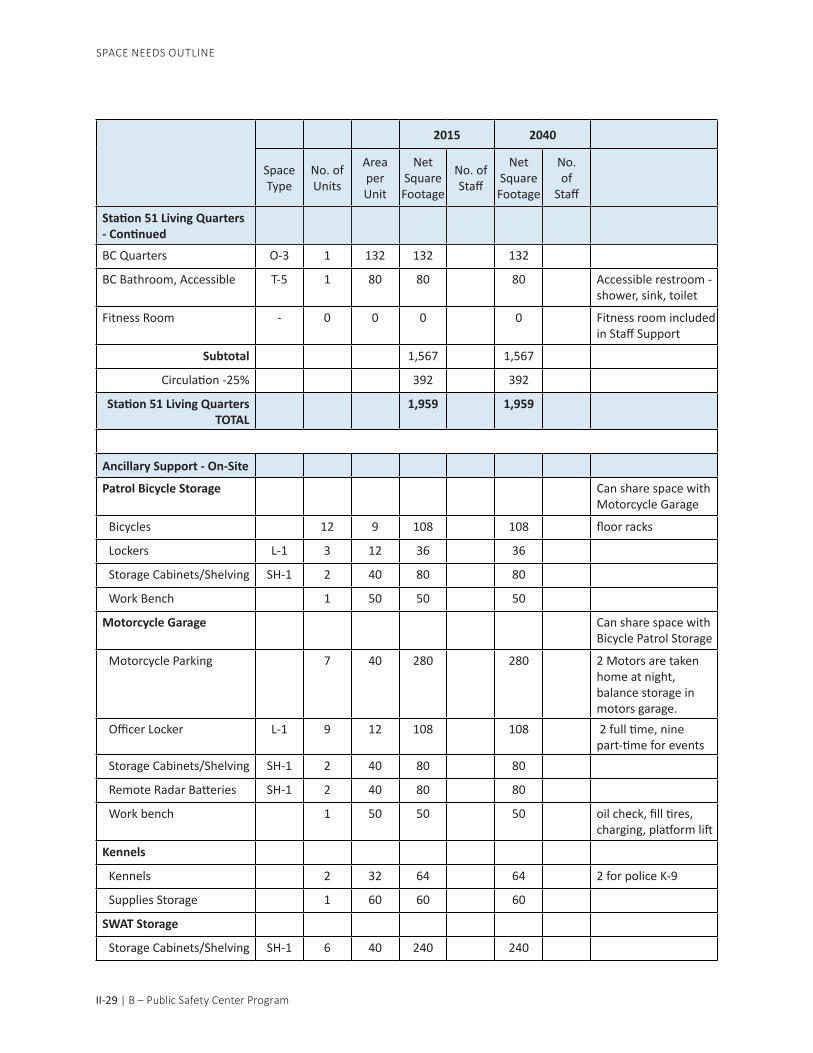
BC Quarters O-3 1 132 132 132
BC Bathroom, Accessible T-5 1 80 80 80 Accessible restroom - shower, sink, toilet
Fitness Room - 0 0 0 0 Fitness room included in Staff Support
Subtotal 1,567 1,567
Circulation -25% 392 392
Station 51 Living Quarters TOTAL
1,959 1,959
Ancillary Support - On-Site
Patrol Bicycle Storage Can share space with Motorcycle Garage
Bicycles 12 9 108 108 floor racks
Lockers L-1 3 12 36 36
Storage Cabinets/Shelving SH-1 2 40 80 80
Work Bench 1 50 50 50
Motorcycle Garage Can share space with Bicycle Patrol Storage
Motorcycle Parking 7 40 280 280 2 Motors are taken home at night, balance storage in motors garage.
Officer Locker L-1 9 12 108 108 2 full time, nine part-time for events
Storage Cabinets/Shelving SH-1 2 40 80 80
Remote Radar Batteries SH-1 2 40 80 80
Work bench 1 50 50 50 oil check, fill tires, charging, platform lift
Kennels
Kennels 2 32 64 64 2 for police K-9
Supplies Storage 1 60 60 60
SWAT Storage
Storage Cabinets/Shelving SH-1 6 40 240 240
SPACE NEEDS OUTLINE
2015 2040
Space Type
No. of Units
Area per Unit
Net Square Footage
No. of Staff
Net Square Footage
No. of
Staff
Station 51 Living Quarters- Continued

B – Public Safety Center Program | II-30
SPACE NEEDS OUTLINE
2015 2040
Space Type
No. of Units
Area per Unit
Net Square Footage
No. of Staff
Net Square Footage
No. of
Staff
SWAT Van and Trailer 0 400 0 0 Store in parking area
CSI Storage
Storage Cabinets/Shelving SH-1 6 40 240 240
CSI Panel Truck 0 200 0 0 Store in Parking Area
Subtotal 1,476 1,476
Circulation -20% 295 295
Ancillary Support - On-Site TOTAL
1,771 1,771
Exterior Spaces - Some parking level, Some at street level.
Evidence Loading Area 1 400 400 400 Adjacent to Property and Evidence
Bulk Marijuana Temporary Holding
2 50 100 100 In exterior storage units to avoid odors filtering into building through the mechanical system
Vehicle Inspection Area - 1 400 400 400 Covered area with air, water, storage for windshield wipers, hoses, etc.
Parking
Visitor Parking 0 350 0 0 All Visitor parking is off-site except ADA
Disabled Access Parking 4 500 2000 2,000
Police Staff Parking 0 350 0 0 Limited, Use City parking above City Hall
Unassigned Vehicle Parking
0 200 0 0
Police Patrol Vehicle Parking
18 400 7200 7,200 18 No Room for on-site vehicle growth
Police Unmarked Vehicle Parking
0 350 0 0 0 No Room for on-sitevehicle growth
Trash Cans at Official Vehicle Parking Area
4 9 36 36
Swat Storage - Continued

II-31 | B – Public Safety Center Program
SPACE NEEDS OUTLINE
2015 2040
Space Type
No. of Units
Area per Unit
Net Square Footage
No. of Staff
Net Square Footage
No. of
Staff
Site Development
Landscaped Areas 1 0 - 0 Site Dependent
Outdoor Plazas 1 0 0 0
Flagpole 1 50 50 50
Staff Courtyards 1 400 400 400 Near lunch room
Patrol Ingress and Egress Points
2 600 1200 1,200 Minimum of 2
Entries
Public Entry 1 200 200 200
Staff Entry 1 200 200 200
Patrol Entry 1 200 200 200
Trash Dumpsters
General Trash 1 200 200 200
On-Site Fueling
Above Grade fueling system 1 200 200 200
Dispensing Area 1 400 400 400
Emergency Power
Emergency Generator 1 200 200 200 for24-hours min.,72 hours is ideal
Fuel Tank 0 400 0 0 Skid mounted tank
Exterior Spaces TOTAL 13,386 13,386
Ancillary Support - Parking Level
4th Street?
Emergency Supply Storage Room
1 600 600 600 Conditioned room, secure from vermin. Emergency slights, kits, food, water, soups, coffee, IPhone Kits, Riot shields, extra gas masks, first aid supplies.
Exterior Spaces - Some parking level, Some at street level - Continued

B – Public Safety Center Program | II-32
SPACE NEEDS OUTLINE
2015 2040
Space Type
No. of Units
Area per Unit
Net Square Footage
No. of Staff
Net Square Footage
No. of
Staff
Field Training Records 1 200 200 200 Conditioned room, secure from vermin. Limited Access
Marine Equipment Storage 1 100 100 100 Parts and accessories
Training Equipment Storage Room
1 200 200 200 Training dummy, mats, training materials, easels, tables and chairs, Phase Training Equip-ment,
Fleet Maintenance Storage
Miscellaneous Storage 4 16 64 64 Tires?
Flares 4 16 64 64
Large Evidence and Vehicle Storage
1 2000 2000 2,000 Moved from both DuBois and 4th street.
Homicide Evidence Storage
1 600 600 600 Moved from DuBois and other locations
Records Storage 1 600 600 600 Moved from DuBoisMessage Board Trailer 1 200 200 200 Moved from street/
PD parking LotRadar Trailer 2 100 200 200 Moved from street/
PD parking LotATV on Trailer 1 200 200 200 Moved from street/
PD parking LotCommand RV 1 200 200 200 Moved from street/
PD parking LotStorage Trailer 1 200 200 200 Moved from street/
PD parking LotHumvee 1 200 200 200 Currently at 4th Street
Subtotal 5,628 5,628
Circulation -10% 563 563
Facility Support TOTAL 6,191 6,191
Ancillary Support - Parking Level - Continued


CITY OF SAN RAFAELESSENTIAL FACILITIES STRATEGIC PLAN
Space standards are developed using the area required for a function adding in the necessary space around the use for circulation. For instance, in determining the size of a lockeroom, each locker is counted plus the space in front of the locker to access it. This is a similar approach followed for each standard. Component diagram use space standards and expand them into room diagrams that graphically illustrate the equipment and furniture arrangements in each required space and are used to determine the room area requirements. Considerations include:
• Number of staff to occupy the space at any given time, • Equipment size and operating clearances, • Circulation within the space, and • Furniture layout for efficient space use.
SPACE STANDARDS AND COMPONENT DIAGRAMS
B. PUBLIC SAFETY CENTER PROGRAM


B – Public Safety Center Program | II-33
SPACE STANDARDSSpace Standard
Category Name/Type of Space Space Categories
Standard Area (Sq. Ft.)
Comments/Approx. Dimensions
Offices Office 1 O-1 224 14’ x 16’
Office 2 O-2 143 11’ x 13’
Office 3 O-3 132 11’ x 12’
Office 4 O-4 120 12’-0” x 10’-0”
Workstations Workstation 1 W-1 80 8’-0” x 10’-0”
Workstation 2 W-2 72 8’-0” x 9’-0”
Workstation 3 W-3 48 8’-0” x 6’-0”
Workstation 4 W-4 24 4’-0” x 6’-0”
Conference Rooms Seating 15 -25 Sq. ft. per occupant
Conference 4 C-4 960 60 chairs
Conference 3 C-3 400 20 chairs
Conference 2 C-2 432 12 - 16 chairs
Conference 1 C-1 180 8 chairs
Lecture/Training Briefing/Training Room B-1 18 Sq. ft. per occupant
Interview Hard Interview I-1 80 For 3 people
Soft Interview I-2 120 For 4 people
Soft Interview - Small I-3 100 For 4 people
Multi-Purpose Room I-4 80Files and Common
Work Area Letter Size File Cabinets F-1 5Sq. ft. each unit, 1’-3” x 4’-0”
Lateral File Cabinets F-2 13.5Sq. ft. each unit,1’-6” x 4’-0”
Work Area F-3 40 5’-0” x 8’-0”
Times-2 Legal F-4 16Sq. ft. each unit, 4’-0” x 4’-0”
Shelving 2-Foot Deep Shelving SH-1 40 2’-0” x 8’-0” + circulation
4-Foot Deep Shelving SH-2 56 4’-0” x 8’-0” + circulation
High-density shelving SH-3 0.16 1 s.f. per 6.4 l.f.. of storage
Bookshelf SH-4 12 1’-0” x 4’-0” + circulation
Computer Rack SH-5 36 4’-0” x 3’-0” + circulation
Electronic Equipment Rack SH-6 14 1’-7” x 3’-0” + circulation
Closets/Storage Private Coat Closet CL-1 8 2’-0” x 4’-0”
SPACE STANDARDS AND COMPONENT DIAGRAMS

II-34 | B – Public Safety Center Program
Unit Coat Closet CL-2 22 sq. ft. per occupant, 2’-0” x 1’-0”
Closed Storage Area CL-3 40 Sq. ft. Closet/Storage -
Continued
Open Storage Area CL-4 40 Sq. ft.
Closed Storage Area CL-5 60 Sq. ft.
Lockers Officer Lockers L-1 12Sq. ft. each unit, 2’ x 2’ x 6’
Staff Lockers L-2 5.5Sq. ft. each unit, 1’-0” x 2’-0” x 6’-0”
Day Lockers L-3 2.75Sq. ft. each unit, 1’-0” x 2’-0” x 3’-0”
Duty Bag Bins l-3 3
Sleeping Area L-4 60Janitor/Toilet/
Shower Janitor’s Closet J-1 50 Sq. ft. 6’-0” x 8’-0”
Toilet 1 T-1 200 Sq. ft. - 4 stalls
Toilet 2 T-2 150 Sq. ft. - 3 stalls
Toilet 3 T-3 125 Sq. ft. - 2 stalls
Toilet 4 T-4 64 Sq. ft. single occupancy
Shower T-5 80 Includes dressing area
Seating Seating in Waiting Areas S-1 15
Seating in Staff Lounges S-2 15
Lunch Room/Support Vending Machines V-1 15
Kitchenette K-1 40
Staff Pantry P-1 20
SPACE STANDARDS AND COMPONENT DIAGRAMS
Space Standard Category Name/Type of Space Space
CategoriesStandard Area
(Sq. Ft.)Comments/Approx.
Dimensions

B – Public Safety Center Program | II-35
LFLFF
LF
F
DEPUTY FIRE MARSHAL (120 S.F.)
FIRE CHIEF OFFICE (224 S.F.)SCALE: 1/8"=1'-0"
SCALE: 1/8"=1'-0"
15 of 26
CITY OF SAN RAFAELESSENTIAL FACILITIES STRATEGIC PLAN
16'-0"
12'-0"
SHELVINGABOVE
14'-0
"
WARDROBECLOSET
BOOKSHELF
10'-0
"
PLAN LAYOUTDESK
SHELVING ABOVE
STORAGE(FILES)
STORAGE (PLANS)
· COMBINED PD/FD - PUBLIC SAFETY CENTERFIRE STATION No. 51FIRE ADMINISTARTION
SPACE STANDARDS AND COMPONENT DIAGRAMS

II-36 | B – Public Safety Center Program
LF
F
F
FIRE ADMINISTRATOR (120 S.F.)MANAGEMENT ANALYST (120 S.F.)SCALE: 1/8"=1'-0"
15 of 26
CITY OF SAN RAFAELESSENTIAL FACILITIES STRATEGIC PLAN
12'-0"
10'-0"
8'-0
"
10'-0
"
"TIMES TWO"7 TIER FILE SYSTEM
SUPPLY STORAGE
SHELVINGABOVE
EMS COORDINATOR (80 S.F.)SCALE: 1/8"=1'-0"
SHELVING ABOVE
· COMBINED PD/FD - PUBLIC SAFETY CENTERFIRE STATION No. 51FIRE ADMINISTARTION
SPACE STANDARDS AND COMPONENT DIAGRAMS

B – Public Safety Center Program | II-37
F
F
15 of 26
CITY OF SAN RAFAELESSENTIAL FACILITIES STRATEGIC PLAN
9'-0"
8'-0
"
SUPPLY STORAGE
MEDICAL DIRECTOR (72 S.F.)NURSE EDUCATOR (72 S.F.)SCALE: 1/8"=1'-0"
SHELVING ABOVE
ADMINISTRATIVE OPEN WORK AREA - 2 (144 S.F.)SCALE: 1/8"=1'-0"
9'-0
"
SHELVING ABOVE,TYP.
"TIMES TWO"7 TIER FILE SYSTEM
VIEW TO LOBBY/RECEPTION COUNTER
8'-0"
· COMBINED PD/FD - PUBLIC SAFETY CENTERFIRE STATION No. 51FIRE ADMINISTARTION
SPACE STANDARDS AND COMPONENT DIAGRAMS

II-38 | B – Public Safety Center Program
F
F
FIRE PREVENTION OPEN WORK AREAFIRE INSPECTOR II - 2 (160 S.F.)SCALE: 1/8"=1'-0"
15 of 26
CITY OF SAN RAFAELESSENTIAL FACILITIES STRATEGIC PLAN
10'-0"
8'-0
"
SHELVING ABOVE
PLAN LAYOUT DESK
STORAGE (INACTIVEFILES & PLANS)
· COMBINED PD/FD - PUBLIC SAFETY CENTERFIRE STATION No. 51FIRE ADMINISTARTION
SCALE: 1/8"=1'-0"EMS OPEN WORK AREA - 3 (216 S.F.)
9'-0"8'
-0" SHELVING ABOVE,
TYP.
"TIMES TWO"7 TIER FILE SYSTEM
SPACE STANDARDS AND COMPONENT DIAGRAMS

B – Public Safety Center Program | II-39
LF
F
15 of 26
CITY OF SAN RAFAELESSENTIAL FACILITIES STRATEGIC PLAN
SCALE: 1/8"=1'-0"
VEGETATION MANAGEMENT SPECIALIST (72 S.F.)ENVIRONMENTAL MANAGEMENT COORDINATOR (72 S.F.)FUTURE PUBLIC EDUCATION SPECIALIST OFFICE/STORAGE (72 S.F.)
9'-0"
8'-0
"
SHELVING ABOVE
· COMBINED PD/FD - PUBLIC SAFETY CENTERFIRE STATION No. 51FIRE ADMINISTARTION
GENERAL STORAGE (60 S.F.)SCALE: 1/8"=1'-0"
10'-0"
6'-0
"
MEDICAL SUPPLYSTORAGE
FULL HEIGHTSHELVING
SPACE STANDARDS AND COMPONENT DIAGRAMS

II-40 | B – Public Safety Center Program
FIRE ADMIN FILE STORAGE (112 S.F.)
FIRE GENERAL STORAGE - SUPPLY (60 S.F.)SCALE: 1/8"=1'-0"
SCALE: 1/8"=1'-0"
15 of 26
CITY OF SAN RAFAELESSENTIAL FACILITIES STRATEGIC PLAN
10'-0"
TO OPENWORK AREA
(4) "TIMES TWO"7 TIER FILE SYSTEM
6'-0
"
MEDICAL SUPPLYSTORAGE
FULL HEIGHTSHELVING
12'-0"
(4) LATERAL FILECABINETS (LOCKING)
9'-4
"
· COMBINED PD/FD - PUBLIC SAFETY CENTERFIRE STATION No. 51FIRE ADMINISTARTION
SPACE STANDARDS AND COMPONENT DIAGRAMS

B – Public Safety Center Program | II-41
15 of 26
CITY OF SAN RAFAELESSENTIAL FACILITIES STRATEGIC PLAN
ADMIN WORKROOM/STORAGE (120 S.F.)SCALE: 1/8"=1'-0"
10'-0"12
'-0"
MAILBOXES
FULL HEIGHTSHELVING
OFFICE SUPPLY/FORMS BASE & UPPERSTORAGE CABINETS
CO
PIER
PLOTTER
· COMBINED PD/FD - PUBLIC SAFETY CENTERFIRE STATION No. 51FIRE ADMINISTARTION
SPACE STANDARDS AND COMPONENT DIAGRAMS

II-42 | B – Public Safety Center Program
30'-0"
TOLARGECONF.
32'-0
"
TOTASK FORCE
CONF.
MAPS
CAD MONITORS TV MONITORS
4'-9
"TO
EQUIPMENTSTORAGE
PROJECTIONSCREENMARKER BOARD
TRAINING ROOMPARTITION
WALL
CITY OF SAN RAFAELESSENTIAL FACILITIES STRATEGIC PLAN
MAIN RESPONSE ROOM/TRAINING CLASSROOM (960 S.F.)
SCALE: 1/8"=1'-0"WALL MAP (144 S.F.)
· COMBINED PD/FD - PUBLIC SAFETY CENTERFIRE STATION No. 51EMERGENCY OPERATIONS CENTER
SPACE STANDARDS AND COMPONENT DIAGRAMS

B – Public Safety Center Program | II-43
15'-0"12
'-0"
F
F
F
F
TO EOC/CLASSROOM
13'-0"
15'-0
"
CITY OF SAN RAFAELESSENTIAL FACILITIES STRATEGIC PLAN
EQUIPMENT STORAGE (195 S.F.)SCALE: 1/8"=1'-0"
CALL TAKER ROOM, HAM RADIO (180 S.F.)SCALE: 1/8"=1'-0"
SHELVINGABOVE
STORAGE(FILES)
· COMBINED PD/FD - PUBLIC SAFETY CENTERFIRE STATION No. 51EMERGENCY OPERATIONS CENTER
CHAIRS & TABLESTORAGE AREA
TRAINING PROPSTORAGE
SPACE STANDARDS AND COMPONENT DIAGRAMS

II-44 | B – Public Safety Center Program
10'-0"12
'-0"
LF LF
F
CITY OF SAN RAFAELESSENTIAL FACILITIES STRATEGIC PLAN
EOC COORDINATOR OFFICE (120 S.F.)SCALE: 1/8"=1'-0"
SHELVINGABOVE
· COMBINED PD/FD - PUBLIC SAFETY CENTERFIRE STATION No. 51EMERGENCY OPERATIONS CENTER
SPACE STANDARDS AND COMPONENT DIAGRAMS

B – Public Safety Center Program | II-45
APPARATUS BAY (2,000 S.F.)SCALE: 1/16"=1'-0"
CITY OF SAN RAFAELESSENTIAL FACILITIES STRATEGIC PLAN
20'-0
"
40'-0
"
50'-0"
TRENCH DRAIN, TYP.
FRONTAPRON
CROSS STAFF 10'x31'
· COMBINED PD/FD - PUBLIC SAFETY CENTERFIRE STATION No. 51STATION - APPARATUS BAY/APPARATUS BAY SUPPORT
APPARATUS BAY - BC VEHICLE (540 S.F.)SCALE: 1/16"=1'-0"
18'-0
"
30'-0"
14'x14' SECTIONALFOUR-FOLD APPARATUS
BAY DOORS, TYP.
RESERVE 10'x31'
BC VEHICLE
20'-0
"
SPACE STANDARDS AND COMPONENT DIAGRAMS

II-46 | B – Public Safety Center Program
MEDICAL SUPPLY STORAGE (40 S.F.)SCALE: 1/8"=1'-0"
CITY OF SAN RAFAELESSENTIAL FACILITIES STRATEGIC PLAN
MEDICAL CLEAN UP (80 S.F.)SCALE: 1/8"=1'-0"
8'-0"
5'-0
"
14" DEEP FULL HT. STORAGE
8'-0"
10'-0
"
BACKBOARD WASH DOWN AREA
S.S. CLEAN-UP SINK w/ DRAINBOARD, HANDS FREE &EMERGENCY EYE WASHABOVE SINK
COUNTER
DRYING RACK ABOVE
· COMBINED PD/FD - PUBLIC SAFETY CENTERFIRE STATION No. 51STATION - APPARATUS BAY/APPARATUS BAY SUPPORT
SPACE STANDARDS AND COMPONENT DIAGRAMS

B – Public Safety Center Program | II-47
1 2 3 4 5 6
12 11 10 9
87
14 1316 15
CITY OF SAN RAFAELESSENTIAL FACILITIES STRATEGIC PLAN
TURNOUT GEAR ROOM (144 S.F.)SCALE: 1/8"=1'-0"
16'-0"
9'-0
"
(16) 24" W x 24" DTURNOUT LOCKERS, TYP.
HEAVY DUTY SHELVINGABOVE, TYP.
WORKSHOP ALCOVE (90 S.F.)SCALE: 1/8"=1'-0"
30'-0"
3'-0
"
PEG BOARD
WORK SPACE w/ AIRQUICK DISCONNECTSSOLVENT TANK
MOBILE HOSESTORAGE RACK
STORAGE CABINET
TOOLCHEST
FREE STANDING SINK VISE
· COMBINED PD/FD - PUBLIC SAFETY CENTERFIRE STATION No. 51STATION - APPARATUS BAY/APPARATUS BAY SUPPORT
SPACE STANDARDS AND COMPONENT DIAGRAMS

II-48 | B – Public Safety Center Program
CITY OF SAN RAFAELESSENTIAL FACILITIES STRATEGIC PLAN
JANITOR CLOSET (50 S.F.)SCALE: 1/8"=1'-0"
5'-0"
10'-0
"
MOP SINK
STORAGE SHELF
MOP RACK
SPECIAL PROJECT ROOM (80 S.F.)SCALE: 1/8"=1'-0"
8'-0
"
FULL HEIGHTSTORAGE
10'-0"
· COMBINED PD/FD - PUBLIC SAFETY CENTERFIRE STATION No. 51STATION - APPARATUS BAY/APPARATUS BAY SUPPORT
SPACE STANDARDS AND COMPONENT DIAGRAMS

B – Public Safety Center Program | II-49
STATION NIGHT LOBBY (84 S.F.)SCALE: 1/8"=1'-0"
CITY OF SAN RAFAELESSENTIAL FACILITIES STRATEGIC PLAN
TO EXTERIOR
TO STATION'SOFFICE
TO ACCESSIBLEUNISEX
RESTROOM
FS13 - STATION PUBLIC RESTROOM - UNISEX (64 S.F.)SCALE: 1/8"=1'-0"
8'-0"
8'-0
"
TO STATIONPUBLIC LOBBY
12'-0"
+32" HIGH COUNTER
+42" HIGH COUNTER
7'-0
"
· COMBINED PD/FD - PUBLIC SAFETY CENTERFIRE STATION No. 51STATION - FIREFIGHTER OFFICES
SPACE STANDARDS AND COMPONENT DIAGRAMS

II-50 | B – Public Safety Center Program
F
LF
F
F
LF
F
F
CITY OF SAN RAFAELESSENTIAL FACILITIES STRATEGIC PLAN
STATION OFFICE (120 S.F.)SCALE: 3/16"=1'-0"
12'-0"10
'-0"
TO LIVINGQUARTERS
PRINTER/FAX/COPIER
RECEPTIONCOUNTER (42" HIGH)
RECEPTIONCOUNTER (36" HIGH)
TRAININGMONITOR
TO STATIONPUBLIC LOBBY
UPPERSTORAGE
BATTALION CHIEF OFFICE (240 S.F.)SCALE: 1/8"=1'-0"
15'-0"16
'-0"
SHELVINGABOVE
PRINTER/FAX/COPIER
· COMBINED PD/FD - PUBLIC SAFETY CENTERFIRE STATION No. 51STATION - FIREFIGHTER OFFICES
SPACE STANDARDS AND COMPONENT DIAGRAMS

B – Public Safety Center Program | II-51
REF A
REF B
MW
DW
COFFEE
KITCHEN (143 S.F.)SCALE: 1/8"=1'-0"
15 of 26
CITY OF SAN RAFAELESSENTIAL FACILITIES STRATEGIC PLAN
11'-0"
13'-0
"RANGE w/ GRILL HOOD
BASE & UPPERCABINET STORAGE
TO DINING AREA
(2) SHIFTPANTRIES
DINING AREA (180 S.F.)SCALE: 1/8"=1'-0"
12'-0"
15'-0
"
· COMBINED PD/FD - PUBLIC SAFETY CENTERFIRE STATION No. 51STATION - FIREFIGHTER QUARTERS
SPACE STANDARDS AND COMPONENT DIAGRAMS

II-52 | B – Public Safety Center Program
D W
15 of 26
CITY OF SAN RAFAELESSENTIAL FACILITIES STRATEGIC PLAN
ENTERTAINMENTCENTER
(6) RECLINERCHAIRS, TYP.
16'-0
"
DAYROOM (224 S.F.)SCALE: 1/8"=1'-0"
14'-0"
LAUNDRY ROOM (120 S.F.)SCALE: 1/8"=1'-0"
12'-0"
10'-0
"
FOLDING COUNTERw/ STORAGE CABINET
FULL HEIGHTSTORAGE CABINET
UTILITY SINK
MOP HOOKS
· COMBINED PD/FD - PUBLIC SAFETY CENTERFIRE STATION No. 51STATION - FIREFIGHTER QUARTERS
SPACE STANDARDS AND COMPONENT DIAGRAMS

B – Public Safety Center Program | II-53
15 of 26
CITY OF SAN RAFAELESSENTIAL FACILITIES STRATEGIC PLAN
FIREFIGHTER BEDROOM - 4 (528 S.F.)SCALE: 1/8"=1'-0"
12'-0
"
11'-0"
(4) LOCKERS
(3) DRAWERSUNDER BED
FIREFIGHTER BATHROOM, ACCESSIBLE (80 S.F.)SCALE: 1/8"=1'-0"
8'-0"
60" M
IN.10
'-0"
30"
MIN.
36"
MIN.
· COMBINED PD/FD - PUBLIC SAFETY CENTERFIRE STATION No. 51STATION - FIREFIGHTER QUARTERS
SPACE STANDARDS AND COMPONENT DIAGRAMS

II-54 | B – Public Safety Center Program
15 of 26
CITY OF SAN RAFAELESSENTIAL FACILITIES STRATEGIC PLAN
FIREFIGHTER BATHROOM (80 S.F.)SCALE: 1/8"=1'-0"
4'-0
"
8'-0
"
3'-6"
10'-0"
BC QUARTERS (132 S.F.)BC BATHROOM, ACCESSSIBLE (80 S.F.)SCALE: 1/8"=1'-0"
11'-0
"
12'-0"8'-0"
10'-0
"
(4) LOCKERS
(3) DRAWERSUNDER BED
· COMBINED PD/FD - PUBLIC SAFETY CENTERFIRE STATION No. 51STATION - FIREFIGHTER QUARTERS
SPACE STANDARDS AND COMPONENT DIAGRAMS

CITY OF SAN RAFAELESSENTIAL FACILITIES STRATEGIC PLAN
This section identifies an overall project budget based on the following items:
• Building and Site Construction Costs w/ Equipment and Furnishings, • Design and other Related Fees, • Administrative, Permit, Bidding Costs, and • Project Contingencies.
OVERALL PROJECT BUDGET
B. PUBLIC SAFETY CENTER PROGRAM


B – Public Safety Center Program | II-55
Combined PD/FD - Public Safety CenterOVERALL PROJECT BUDGET
A. Construction with Contingencies and Escalation
QUANT UNIT Cost per Unit Total Notes
Public Safety Center
Replacement PSC 44,666 LS $500 $22,332,819 Cost per square foot budget
On-Site Improvements (Fifth Street) 40,000 SF $50 $2,000,000
Retaining walls, utility, Grading and Drainage, parking, fences and gates, landscaping.
Haz Mat Demo/Bldg. Demo 10,000 SF $15 $150,000Demolition of 4 existing buildings
Off-Site Improvements 1 LS $250,000 $250,000 Allowance
Temporary Facilities 1 LS $500,000 $500,000FD to relocated during construction
Specialty Equipment 5% % $25,232,819 $1,261,641Contractor Provided Equipment
Construction Subtotal: $26,494,460
Project Design Unknowns 15% % $26,494,460 $3,974,169 Allowance
Construction with Design Unknowns Subtotal: $30,468,629 Project Allowance
Construction Contingency (10% of Construction) 10% % $30,468,629 $3,046,863 Allowance
Construction with Change Order Contingency Subtotal: $33,515,492 Project Allowance
Project Escalation (5% per annum, compounded yearly) 12% % $33,515,492 $4,021,859
Annual rate to midpoint of Construction = 24 months (14 months design and 20 months construction)
Construction (Building Site, Equipment, Contingencies, Escalation): $37,537,350
Construction Cost per SF of Building Area: $1,112
B. Design and Other Related Fees
QUANT UNIT Cost Per Unit TOTAL Notes
Design Fees (A, C, L, S, MEP) - BASIC ON-SITE 10% % $37,537,350 $3,753,735
A/E fees including entitlements
OVERALL PROJECT BUDGET

II-56 | B – Public Safety Center Program
Off-site/Street Improvement Drawings 15% % $250,000 $37,500
design for off site improvements
Cost Estimating 1 LS $35,000 $35,000Estimate for each phase of development
Boundary and Topographic Surveys 1 LS $25,000 $25,000 Includes recording map
Erosion Control Plan 1 LS $7,500 $7,500Per Bldg. Department Requirements
Waterproofing Consultant 1 LS $30,000 $30,000 Consultant to City
Lighting Designer 1 LS $30,000 $30,000 Optional
Head In Data, Phone, Response, Security, AV Consultant 1 LS $75,000 $75,000 Consultant to City or Arch.
LEED Documentation 1 LS $100,000 $100,000Energy Modeling, LEED submittal and Tracking
Construction Management (5% of construction value) 5% % $37,537,350 $1,876,868
Day to day management during construction
Geotechnical Investigation 1 LS $30,000 $30,000 Includes geohazards report
Haz Mat Study (Ground and (E) buildings) 1 LS $30,000 $30,000 Study only
Environmental (CEQA) Documentation 1 LS $50,000 $50,000 Assume Neg Dec.
Commissioning 1 LS $50,000 $50,000 As Required for LEED Gold
Continuous Inspection, Testing During Construction 1 LS $150,000 $150,000 Allowance
Subtotal Design Fees: $6,280,603Fee Contingency (5% of total
Fees) 5% % $6,280,603 $314,030 AllowanceReimbursables (5% of total
Fees) 5% % $6,280,603 $314,030 Project Allowance
Total Design and Other Related Fees: $6,908,663
C. Administrative, Permit and Bidding CostsQUANT UNIT Cost Per Unit Total Notes
Administration Costs - LS $0 $0Assume none charged to project
OVERALL PROJECT BUDGET
B. Design and Other Related Fees - Continued
QUANT UNIT Cost Per Unit TOTAL Notes

B – Public Safety Center Program | II-57
Legal Fees 1 LS $60,000 $60,000 Allowance
Building Permit Costs 1% % $37,537,350 $375,374 Per Building Department
Plan Check Fees 0.5% % $37,537,350 $187,687 Per Building Department
SWPP Fees (State Board Compliance) 1 LS $5,000 $5,000 Allowance
Planning/Environmental Review Fees 1 LS $40,000 $40,000 Allowance
Temporary Storage Costs - LS $25,000 $0 Assume none required
Public Art 1 LS $50,000 $50,000 Allowance
Specialty Equipment 3% % $24,332,819 $729,985Allowance for Owner pro-vided Equipment
Furnishings 5% % $22,332,819 $1,116,641 Allowance
Bidding/Printing (noticing, blueprints, etc.) 1 LS $10,000 $10,000 Allowance
Moving Costs (one move) 1 LS $15,000 $15,000 Allowance
Utility Fees - (PG&E, sewer, water, telecom, other) 1 LS $250,000 $250,000 Allowance
Subtotal Administrative Costs: $2,839,686
Administrative Cost Contingency (5% of total Fees) 5% % $2,839,686 $141,984 Allowance
Total Administrative, Property, and Bidding Costs: $2,981,670
Division Totals:
Total Notes
A. Construction with Contingencies and Escalation $37,537,350
B. Design and Other Related Fees $6,908,663
C. Administrative, Permit and Bidding Costs $2,981,670
Overall Project Budget: $47,427,683
Project Cost Per SF : $40,405,249/41,840 SF= $1,405
Exclusions:
1. Program Level Bond Management Fees
OVERALL PROJECT BUDGET
C. Administrative, Permit and Bidding Costs - Continued
QUANT UNIT Cost Per Unit TOTAL Notes


CITY OF SAN RAFAELESSENTIAL FACILITIES STRATEGIC PLAN
These studies graphically illustrate the initial arrangement concepts developed through discussion with the Project Design Team. Considerations in each scheme include:
• Circulation to and from site, • Visitor parking and pedestrian access, • Site operations adjacencies and activities, and • City of San Rafael planning ordinances
SITE ARRANGEMENT DIAGRAMS
B. PUBLIC SAFETY CENTER PROGRAM


FINAL 7/20/15 CITY OF SAN RAFAELESSENTIAL FACILITIES STRATEGIC PLAN
B – Public Safety Center Program | II-58
SCALE: 1:500
SITE/FIRST LEVEL LAYOUT
SITE ARRANGEMENT DIAGRAMS


FINAL 7/20/15 CITY OF SAN RAFAELESSENTIAL FACILITIES STRATEGIC PLAN
B – Public Safety Center Program | II-59
SCALE: 1:500
SITE/SECOND LEVEL LAYOUT
SITE ARRANGEMENT DIAGRAMS


FINAL 7/20/15 CITY OF SAN RAFAELESSENTIAL FACILITIES STRATEGIC PLAN
B – Public Safety Center Program | II-60
SCALE: 1:500
SITE/FIRST & SECOND LEVEL LAYOUT
SITE ARRANGEMENT DIAGRAMS


FINAL 7/20/15 CITY OF SAN RAFAELESSENTIAL FACILITIES STRATEGIC PLAN
CITY OF SAN RAFAEL DRAFT ESSENTIAL FACILITIES STRATEGIC PLAN JUNE 22. 2015
A – Introduction | II‐
VOLUME II. DETAILED FACILITY STUDY – PUBLIC SAFETY CENTER
EXISTING FACILITY ASSESSMENTS
FIRE STATION 51 – 1039 C STREET
Fire Station 51 is located at the corner of C Street and 5th Avenue in downtown San Rafael and serves the downtown and western portions of the City. Fire Station 51 was originally built in 1917, and as the oldest fire station in San Rafael has been upgraded several times, most recently in 1986 to its current size of 9,411 square feet. Fire Station 51 is a two‐story facility that was initially designed before the Uniform Building Code. Beyond seismic and building system obsolescence, renovation of the structure would be significantly hampered by the fact that the first floor has many levels and the second story is without code required exiting or accessibility elements.
The station serves as the headquarters and administration for SRFD. The administrative offices, originally built to accommodate a smaller number of employees, are overcrowded and do not fulfill the needs of the department. The Fire Prevention Bureau and clerical staff squeeze into cubicles designed for half as many personnel and these functions occur on two different levels within the same space without accessible ramps or lifts. The conference room doubles as records storage, and is lined with file cabinets. Members of the public who visit the offices find that there is little space available for activities such as plan checks.
Due to the station’s construction date many aspects of the building are not code compliant and would require updating that would render the station unusable from a spatial standpoint. As noted above, Fire Station 51 is built on a sloping site and has many stair transitions throughout the building interior. Meeting accessibility requirements with transitions between the three levels would utilize a significant amount of floor space rendering the station mostly unusable for fire suppression and protection services. Additionally, the second floor does not have a code compliant stair or a code compliant second exit for the second floor. The facility is not served by an elevator which would be required in any renovation. Adding two stairs and an elevator would take up more necessary operational area. There is not space on the site to add either and maintain current operations. In addition, the station lacks insulation and has single glazed windows. The outdated electrical and plumbing systems, poor air conditioning system, and inefficient single glazed windows result ineffective work environments, potential safety hazards and costly maintenance and repairs.
In addition to obsolete seismic and building systems, the fire station layout lacks spaces necessary to support a modern work force. Spaces lacking but required for firefighter safety include dedicate turnout storage, medical clean up and medical supply storage, and a dedicated fitness room. The station also lack privacy necessary to support a diverse workforce including private sleeping and bathing facilities for female firefighters.
At 98‐years‐old, this station is beyond modernization and is at the end of its life‐cycle.
Primary deficiencies include:
Even with renovation in the 1980s, the station remains seismically unsafe and has failing structural systems. The Essential Services Building Act, enacted in 1990, outlines that “It is the intent of the Legislature that
C – Existing Facility Assessments | II-61

FINAL 7/20/15CITY OF SAN RAFAELESSENTIAL FACILITIES STRATEGIC PLANDRAFT CITY OF SAN RAFAEL
JUNE 22. 2015 ESSENTIAL FACILITIES STRATEGIC PLAN
11‐ | A – Introduction
essential service buildings, which shall be capable of providing essential services to the public after a disaster, shall be designed and constructed to minimize fire hazards and to resist, insofar as practical, the forces generated by earthquakes, gravity, and winds.” This facility was assessed in 2003 and then again through this study. Both assessments concluded that, structurally, Fire Station 51 has significant dry rot damage, differential settlement of perimeter walls, water damage, and seismic cracking. Repairing these deficiencies while updating the facility to meet current seismic code would be cost prohibitive compared to providing a new facility.
Fire Station 51, as currently exists, is built on a sloping site and has many stair transitions throughout the building interior. Meeting accessibility requirements with transitions between the three levels would utilize a significant amount of floor space rendering the station mostly unusable for fire suppression and prevention services.
The second floor does not have a code compliant stair or a code compliant second exit for the second floor. There is not space on the site to add either and maintain current operations.
Fire Station 51 does not have an elevator which would be required in any significant upgrade and there is no site area to provide one.
The current apparatus bays openings are not large enough to accommodate a fire truck. A fire truck at this location will provide a key response improvement in the downtown response area and in the proposed Public Safety Facility program.
The fire station layout lacks basic operational spaces required to accommodate todays firefighting operations and a modern workforce.
The existing plumbing systems in the building are mostly original and are nearing the end of their service life. The existing fixtures are outdated and are not water‐conserving fixtures.
The mechanical systems in both the fire station and the administrative areas are greater than 15 years old, are not energy efficient and have outlived their average service life and would require complete replacement.
The building is not supported by a fire alarm system nor is it protected by fire sprinklers. These would need to be added.
The communications room is installed under a significant plumbing route and there have been ongoing issues with plumbing line leaking on to sensitive data equipment. It would need to be relocated.
II-62 | C – Existing Facility Assessments

FINAL 7/20/15 CITY OF SAN RAFAELESSENTIAL FACILITIES STRATEGIC PLANCITY OF SAN RAFAEL DRAFT
ESSENTIAL FACILITIES STRATEGIC PLAN JUNE 22. 2015
A – Introduction | II‐
Supporting Documents including a detail seismic analysis, mechanical, electrical and plumbing assessments follow in the attached appendix.
San Rafael Strategic Plan Tier 1 ‐ Fire Station No. 51 Structural Review and Conditional Assessment Prepared by Cornerstone Structural Engineering Group Dated: June 23, 2015 Basis of Design Narrative ‐ Fire Station 51 City of San Rafael ‐ Essential Facilities Strategic Plan MEP Review and Conditional Assessment Prepared by Interface Engineering Dated: June 22, 2015
CITY HALL – 1400 5TH AVENUE
City Hall is a 26,500‐square‐foot structure that was originally constructed in 1965. The building was originally designed using the 1964 Uniform Building Code. The facility consists of the main building which is occupied by the city offices and police station and the council chambers building that is constructed to the west of the main building. The main building and council chambers are connected at the second floor level of the main building by a 1,100‐square‐foot lobby. The design of this facility is shown on the architectural drawings prepared by San Rafael Architects Associated and the structural drawings prepared by Engle and Engle, Civil and Structural Engineers. The drawings are dated April 19, 1965. The building is of mixed concrete and reinforced masonry construction.
The building, when studied in 2003, was found to be in “fair” condition seismically and is “likely to survive a major earthquake with moderate damage”. The most recent renovation was to the first floor police area primarily to install an energy efficient HVAC system. It was also intended to improve the safety of the lobby and create new locker spacing for both male and female officers and staff. In addition to the newer locker and restrooms the space includes a group of private and open office spaces, meeting rooms and storage. Modular trailers and storage units have been added in the parking lot to support the police operations.
As a part of this Essential Facilities Strategic Plan process one option included an evaluation of upgrading the City Hall building and adding an annex in the east parking lot area to accommodate the Police Department programmed needs. It was determine that the entire City Hall building would require a seismic upgrade and new fire sprinklers to house the SRPD in just a small portion of it. The added cost to the Measure E program to upgrade City Hall to meet only a portion of the Police Department need did not make sense. It was reaffirmed that the Measure E funds were dedicated to providing seismic safe essential facilities and the cost to update City Hall was not necessarily part of that mandate. Also, the cost to upgrade the entire City Hall and add an approximately 25,000‐square‐foot annex was significantly more than it would cost to build a new police station across the street and this option was consequently eliminate. The first floor area of City Hall will become available to other City functions once the new Public Safety Center is completed. However, the new users have not yet been identified and the scope of needed adjustments has not been defined. The budget range is a placeholder until additional programming takes place.
C – Existing Facility Assessments | II-63


CITY OF SAN RAFAELESSENTIAL FACILITIES STRATEGIC PLAN
San Rafael Strategic Plan Tier 1 - Fire Station No. 51Structural Review and Conditional Assessment Prepared by Cornerstone Structural Engineering GroupDated: June 23, 2015
Basis of Design Narrative - Fire Station 51City of San Rafael - Essential Facilities Strategic PlanMEP Review and Conditional Assessment Prepared by Interface EngineeringDated: June 22, 2015
APPENDIX


Structural Engineering ٠ Construction Services ٠ Engineering Solutions ٠ Project Management
San Rafael Strategic Plan Tier 1 - Fire Station No. 51 City of San Rafael
San Francisco, CA
Structural Review and Conditional Assessment FINAL DRAFT June 23, 2015
40 Federal Street
San Francisco, CA 94107
tel (415) 369-9100
fax (415) 369-9101
CORNERSTONE structural engineering group


40 Federal Street
San Francisco, CA 94107
tel (415) 369-9100
fax (415) 369-9101
CORNERSTONE
www.cseg.com
structural
engineering
group
June 23, 2015
2015014.11
Mary McGrath Architects
505 17th Street, 2nd Floor
Oakland, CA 94612
Attention: Mary McGrath
Subject: San Rafael Strategic Plan – Fire Station No. 51
Tier 1 Structural Assessment of Public Safety Facilities
San Rafael, CA
Dear Mary
Cornerstone Structural Engineering Group would like to present this initial structural assessment
report for the subject project. In accordance with our proposal, we have performed a structural
review and seismic risk assessment for the existing Fire Station Building No. 51 in San Rafael. This
report contains the evaluations of the two-story cast-in-place concrete and wood frame
building with shear walls originally constructed in approximately 1915.
We completed a site visit in March 2015, and have reviewed the available structural plans. This
review includes a Tier 1 ASCE 31 seismic evaluation for Immediate Occupancy in addition to a
conditional assessment of the buildings. The Tier 1 assessment includes a general review of the
vertical and lateral systems of the structures.
The following report describes the findings of our structural review and seismic risk assessment for
the buildings. We have included information on the performance of the buildings in a code-
level earthquake.
Sincerely,
CORNERSTONE STRUCTURAL
ENGINEERING GROUP, INC.
Thomas L. Swayze, S.E.
Principal


CORNERSTONE structural engineering group
1 of 11
San Rafael Facilities Master Plan- Structural Assessment
TABLE OF CONTENTS
PART 1: INTRODUCTION ............................................................................................................................... 2
PART 2: SEISMIC PERFORMANCE EVALUATION ......................................................................................... 2
2.1 Methodology ........................................................................................................................................ 2 2.2 Performance Level .............................................................................................................................. 3 2.3 Seismic Source...................................................................................................................................... 3 2.4 Liquefaction, Landslide, and other Geologic Hazard.................................................................. 3
PART 3: STRUCTURAL EVALUATION ............................................................................................................. 4
3.1 Evaluation ............................................................................................................................................. 4 3.2 Documentation.................................................................................................................................... 4 3.3 Vertical Load Systems ......................................................................................................................... 5 3.4 Lateral Load System ............................................................................................................................ 5 3.5 Conditional Review ............................................................................................................................. 5 3.6 Seismic Evaluation Findings ............................................................................................................... 6
PART 4: CONCLUSION AND RECOMMENDATIONS ................................................................................... 6
4.1 Expected Performance ...................................................................................................................... 6 4.2 General Recommendation for Conditional Issues ........................................................................ 7 4.3 Seismic Recommendations ............................................................................................................... 7
PART 5: APPENDIX - PHOTOS ...................................................................................................................... 8


CORNERSTONE structural engineering group
2 of 11
San Rafael Facilities Master Plan- Structural Assessment
PART 1: INTRODUCTION
The following represents a general structural conditional and seismic assessment of the existing
Fire Station No. 51 located in San Rafael, California. Fire station 51 is a two story concrete and
wood framed structure on a sloping site in downtown San Rafael. There are two apparatus bays
within the station and one additional bay exiting to 5th Avenue that was added at the rear of
the station in 1986. The original construction is from approximately 1915.
Figure 1: Station 51
A site visit was performed on March 20, 2015 to observe the existing structural conditions of the
fire station building.
The report conclusions are limited by the availability of as-built construction documents and by
the level of access possible for the observation of the building. This report describes the findings
of our structural review, and provides recommendations for seismic upgrade and conditional
structural repairs as applicable.
PART 2: SEISMIC PERFORMANCE EVALUATION
2.1 Methodology
The potential damage to a structure in an earthquake can be evaluated provided that,
(1) seismic hazards which affect the structure and site can be estimated and, (2) the
vulnerability of the structure to those hazards are known or can be estimated.
Seismicity of the fire stations was determined using the United States Geologic Survey
(USGS) web based Seismic Hazard Curves, Response Parameters and Design Parameters
program. Seismic short period SS and one second S1 response acceleration parameters
were obtained using latitude and longitude coordinates of the fire station location.
Seismic evaluations of the buildings were conducted using the ASCE 31-03 – Seismic
Evaluation of Existing Buildings. The ASCE 31 provides a three-tiered process for seismic
evaluation of existing buildings based on building type and the level of seismicity for the
building location. The Tier 1 study is an initial checklist evaluation of structural, non-
structural and foundation/geologic hazard elements of a building and site conditions
that is intended to screen for potential seismic deficiencies. Tiers 2 and 3 studies are
more in-depth analysis procedures for a building or component that is identified by the
Tier 1 screening process as structurally deficient.

CORNERSTONE structural engineering group
3 of 11
San Rafael Facilities Master Plan- Structural Assessment
This assessment of the fire station building utilizes the Tier 1 screening procedure to
identify deficiencies as possible with the information available.
2.2 Performance Level
ASCE 31 evaluation of a building can be performed for either Life Safety (LS) or
Immediate Occupancy (IO) performance level.
ASCE 31 generalizes the two performance levels as follows:
LS Performance Level: At least some margin against either partial or total
collapse remains, and that the overall risk of life-threatening injury as a result of
structural damage is expected to be low.
IO Performance Level: After an earthquake, the basic vertical and lateral force-
resisting systems retain nearly all of their pre-earthquake strength, very limited
damage to structural and non-structural components has occurred and that
critical parts of the building are habitable.
The fire station building was evaluated using the Immediate Occupancy (IO)
performance level criteria.
2.3 Seismic Source
The general seismicity in the San Francisco Bay Area is influenced by several known
faults, their potential faulting length, and relative orientation. The San Andreas Fault
system, which separates the North American plate from the Pacific plate, is located
approximately 15 km west of the fire stations. Other known, nearest-site faults with
recorded activity, such as the Hayward Fault are listed in Table 1.
Recent earthquakes in Southern and Central California – namely Coalinga, Whittier
Narrows, and Northridge – have occurred along blind-thrust faults. These faults do not
have readily identifiable surface features and are not extensively mapped. The potential
for strong-ground motion to occur due to blind-thrust faulting in Northern California is
somewhat in doubt. However, a moderate to large earthquake centered even closer to
the site cannot be completely ruled out.
Distance (km) San Andreas Fault
[Type A]
San Gregorio Fault
[Type B]
Hayward Fault
[Type A]
Estimated MCE (MW) 7.1 7.2 6.4
Station 51 14.6 15.8 13.7
Table 1: Active Near Source Faults
Based on the 2008 USGS mapping, the 475-year peak ground acceleration (PGA) for the
site is 0.500g. The 475-year earthquake is the design basis for a standard structure in the
California Building Code (CBC) and is based on a 10 percent probability of exceedance
within a 50 year time frame.
The calculated site specific SDS and SD1 response acceleration parameters for the fire
station are 1.0 and 0.60 respectively and use a site soil classification D per USGS Soil Type
and Shaking Hazard in the San Francisco Bay Area Map. Based on SDS and SD1 values,
ASCE 31 categorizes the seismicity of the fire station as ‘High.’
2.4 Liquefaction, Landslide, and other Geologic Hazard
Currently published California Geological Survey (CGS) liquefaction hazard zone maps
do not include this part of California yet. According to the Association of Bay Area
Governments Earthquake Liquefaction Susceptibility maps, the fire station is located

CORNERSTONE structural engineering group
4 of 11
San Rafael Facilities Master Plan- Structural Assessment
within a ‘Low’ zone for liquefaction, see Figure 5. Liquefaction is the loss of bearing
strength of saturated, cohesionless soils under strong ground motions, which can cause
building settlement by consolidation of soils susceptible to liquefaction. Based on the
hazard maps and a cursory knowledge of the soils in the area, the potential for
liquefaction due to strong ground motions at station 51 is considered to be low.
The building is situated on various kinds of sites within a developed area. The potential
for seismically induced landslide is therefore considered to be minimal. Currently
published CGS maps for landslide vulnerability do not include this area yet.
Figure 2: Association of Bay Area Governments Earthquake
Liquefaction Susceptibility Map – Very High (Maroon) & Low (Green)
The fire station is not located within a Special Study Zone as defined by the Alquist-Priolo
Earthquake Fault Zoning Act. The potential for surface fault rupture is considered to be
low.
It should be noted that a more thorough explanation of site seismicity, liquefaction and
specific faulting hazards should be provided by a geotechnical engineer. The
conclusions above rely on general USGS & CGS published data for the San Francisco Bay
Area.
PART 3: STRUCTURAL EVALUATION
3.1 Evaluation
An ASCE 31 Tier 1 seismic evaluation of the fire station was performed using the
Immediate Occupancy performance level. The building was evaluated for Basic
Structural (Sec. 3.7), Supplemental Structural (Sec. 3.7S) and Geologic Site Hazard and
Foundation (Sec. 3.8) checklists. This report does not evaluate the buildings for the
Nonstructural (Sec. 3.9) checklist, which is typically performed by an Architect or other
qualified professional.
3.2 Documentation
No original written documentation available for the 1915 construction or subsequent
remodels.
Station 51

CORNERSTONE structural engineering group
5 of 11
San Rafael Facilities Master Plan- Structural Assessment
Plans from a 1986 modernization are available. Structural Drawings by
Robelo/Kocjan Associates from Redwood City. Sheets FS1-FS5. Drawings dated
March 19, 1986.
The information provided within this report regarding the buildings is based on field
observation and review of available as-built drawings.
3.3 Vertical Load Systems
Note this data is based on previously issued conceptual framing plans from an evaluation
report performed in 2002 and from the 1986 modernization plans.
The upper roof and second floor framing likely consists of 3/4 inch straight
sheathing over wood framing and wood and steel beams. The original
apparatus bay appears to have cast-in-place concrete wall construction
(possibly with encased structural steel columns and beams) surrounding the
apparatus bay with a concrete slab on grade.
The one story low wing on the north was added after the original construction
and appears to be wood framed with wood framing and straight sheathing. This
section of the building appears to be supported on mostly wood framed
studwalls and likely founded on conventional spread footings. There appear to
be some existing concrete walls in this area from the 1986 drawings. There is a
raised wood framed floor at the ground level
The apparatus bay at the rear of the station (1986 addition) and the small bay on
the south side of the building appear to have been added after the original
construction. The south wing consists entirely of wood frame construction likely on
conventional spread footings, while the rear bay consists of wood roof framing on
CMU (Concrete Masonry Unit) walls, likely on conventional spread footings
3.4 Lateral Load System
Lateral loads acting on the fire station building result from either wind pressure or
earthquake-induced inertia forces acting on structural and non-structural elements.
Lateral loads acting on the structure are transferred through flexible roof and floor
diaphragms to the primary lateral-force resisting system of the structure. The primary
lateral-force resisting systems consist of the following systems (limited anecdotal
information available):
Roof and floor diaphragms are likely constructed of straight sheathed
diaphragms spanning to archaic cast-in-place concrete, CMU, or wood shear
walls (undocumented) which transfer lateral loads down to the concrete spread
footings.
3.5 Conditional Review
Based on our review, the fire station building appears to be in general compliance with
the codes and standard construction practices in effect at the time of their construction.
The exterior, interior, and portions of the roof of the fire station were observed during the
site visit on March 20, 2015. Based on our cursory observations, the building appears to
be in overall good condition, except for the following specific conditions as noted (see
Appendix for photos referenced):
Some evidence differential settlement of the perimeter walls at various additions
and window openings is evident. (See Photos 2 & 3)
Dry rot damage is evident at apparatus bay door and wooden windows.
Although structural elements are not visible, it is likely that this damage extends to
lower portions of wood stud walls. (See Photos 4 & 5)

CORNERSTONE structural engineering group
6 of 11
San Rafael Facilities Master Plan- Structural Assessment
Previous water damage is evident from the underside of the first floor. (See Photo
6)
Seismic cracking is evident in surface plaster at building interior. Anecdotally, this
damage is a result of the recent Napa earthquake. (See Photo 7)
3.6 Seismic Evaluation Findings
Based on the ASCE 31 Tier 1 review, the following items are of significance for the
performance of the building when subjected to strong ground motions during an
earthquake. Note that limited as-built information is available.
Positive Features
Low rise wood framed structures are relatively lightweight and historically perform
well in seismic events.
Negative Features
The longitudinal shear walls at the first floor are likely to be overstressed per the
allowable limits within the Tier 1 evaluation.
Wood shear walls do not appear to have hold-down anchors to the foundation.
Footing information is not available but it is likely that footings are inadequate for
primary system seismic forces.
Shear walls do not likely have interconnection between the first and second
stories capable of transferring overturning and shear forces through the floors to
shear walls below.
There exists a split-level diaphragm between the second floor and the low roof
above the offices and other added areas. This effectively splits the building in
multiple parts and presents vulnerability for separation at this joint where the floor
step occurs.
There appears to be a lack of roof and floor –to-wall ties for out-of-plane seismic
forces, as well as a lack of cross building ties for concrete perimeter walls at
apparatus bays.
PART 4: CONCLUSION AND RECOMMENDATIONS
4.1 Expected Performance
Findings within this report provide a general structural conditional and seismic assessment
of the existing building of the San Rafael Fire Station No. 51 located at 1039 C. Street in
San Rafael, CA. Our evaluation concludes that the building fails to meet full compliance
for ASCE 31 Tier 1 Immediate Occupancy performance criteria.
The following structural relative performance descriptions are based on our professional
engineering judgment and experience, and are not part of the ASCE 31 Tier 1 checklist.
These descriptions are included to provide a general estimation of seismic performance
of the structure, based on component evaluations provided by the Tier 1 evaluation
procedure. We expect the building to perform as follows:
The building is anticipated to perform below average in comparison to buildings
of similar construction when subjected to a design level earthquake, due to
overstressed shear walls, discontinuous shear walls, lack of hold downs, and
geometric irregularities.

CORNERSTONE structural engineering group
7 of 11
San Rafael Facilities Master Plan- Structural Assessment
4.2 General Recommendation for Conditional Issues
The following recommendations are provided to address issues concerning the condition
of the existing fire station building. While none of these represent immediate life safety
issues; it is recommended that these issues be addressed in the near future to prevent
further deterioration from occurring:
There is evidence of water damage and dry rot at exposed wood elements
around the perimeter of the building. It is likely that sill plates and lower portions
of stud wall framing will be discovered as conditions are exposed. Many areas of
wood framing are covered by architectural finishes and cannot be observed
without destructive investigation. A significant allowance should be maintained
to accommodate moisture damage repairs in kind.
First floor framing should be exposed, evaluated and replaced in kind as water
staining and damage was noted in both joists and decking elements.
Seismically damaged elements from the recent Napa earthquake should be
removed and replaced.
4.3 Seismic Recommendations
The following qualitative recommendations are provided to address our opinion of the
potential remediation options for identified seismic deficiencies. These methods are
based on our evaluations described elsewhere in this report and engineering judgment.
While the recommendations listed below do not represent any immediate concerns that
warrant facility closure, they do describe building components that are non-compliant
per the ASCE 31 Tier 1 checklist review for Immediate Occupancy performance or as
identified by conditional or systemic deficiencies. We recommend these repairs and
seismic upgrades are programmed into a future project:
Add plywood sheathing to roof, second floor, first floor, perimeter wood walls and
designated interior wood walls.
Add new reinforced concrete (shotcrete) walls over existing concrete walls in
discrete locations in apparatus bay. New footings will be required at new
concrete overlays.
Provide out-of-plane roof to wall ties to concrete wall elements along with cross
building ties to wood diaphragms.
Install new hold-downs and potentially new footing supplements at existing shear
walls at the ground floor slab/foundation level.
Install straps between first and second story shear walls to provide inter-story
continuity.
Provide a collector tie at shear wall lines along the roof, second floor and at roof
plane discontinuity interfaces to provide continuity across the split-level
diaphragms so that seismic load can be delivered to shear walls as they occur.
Note: The existing station 51 has been renovated and remodeled many times since its
original construction and there is virtually no documentation on the various systems used.
This means that during execution of a seismic retrofit, it should be expected that a
number of unforeseen issues will arise that will need to be dealt with during construction.
Given the extent of the suggested strengthening components, and the demolition
necessary to access those areas, it may be difficult to justify the costs necessary to
strengthen the building versus total replacement. Feasibility of re-use of the facility
should be carefully considered with the programming needs and anticipated
construction costs prior to proceeding with a seismic retrofit design.

CORNERSTONE structural engineering group
8 of 11
San Rafael Facilities Master Plan- Structural Assessment
PART 5: APPENDIX - PHOTOS
Photo 1: Station 51, Front View of Building
Photo 2: Station 51, Cracks in Perimeter Walls

CORNERSTONE structural engineering group
9 of 11
San Rafael Facilities Master Plan- Structural Assessment
Photo 3: Station 51, Cracks in Perimeter Walls
Photo 4: Station 51, Dry Rot Damage on App Bay Doors

CORNERSTONE structural engineering group
10 of 11
San Rafael Facilities Master Plan- Structural Assessment
Photo 5: Station 51, Dry Rot Damage on Wood Studs
Photo 6: Station 51, Water Damage on Underside of Floor

CORNERSTONE structural engineering group
11 of 11
San Rafael Facilities Master Plan- Structural Assessment
Photo 7: Station 51, Seismic Cracking in Plaster

Basis of Design Narrative
- Fire Station 51
City of San Rafael - Essential Facilities Strategic
Plan
2015-0131
prepared for:
Mary McGrath Architects
prepared by:
Eunice Yoon, PE, LEED AP, BD+C
Jared Doescher, PE, LEED AP
Jason Lau, PE, LEED AP
Thomas de Senna, PE
June 22, 2015


T:\2015\2015-0131\Comm\Outgoing\2015-06-24 Final BOD Reports\51 Fire Station\20150624_Final BOD Report - Fire Station 51.docx
Assessment of Current City of San Rafael Essential Facilities Fire Station #51
o Mechanical Assessment
Fire Station #51 is a two-story building with attached single story office building. The
living quarters are located on the second floor and are served by a 17-year old, 6-ton
rooftop package unit (RTU) located on the roof. The RTU provides electric cooling and
gas-furnace heating. The majority of the ductwork is round, roof mounted ductwork. The
ductwork appears to be reasonable shape for 17 years old. Ventilation is provided by the
RTU. Operable windows are currently installed. This RTU also serves the workout room
and small front office. This RTU has outlived the average service life of 15 years.
The kitchen is has a commercial range/oven with an inefficient oversized commercial
exhaust hood. The kitchen hood is exhaust directly by an upblast exhaust fan on the roof.
Make-up air for the hood is provided by a rooftop forced air furnace, age unknown but
appears to be over 20 years. The Toilet and Shower rooms are provided with ceiling
mounted exhaust grilles connected to an inline exhaust fan and terminates at roof
louvers/hood.
The Admin Office area has a 16-year-old, 5-ton gas/electric rooftop package unit.
Ductwork is located above the ceiling, serving ceiling diffusers in the offices. This RTU
has outlived the average service life of 15 years.
The Apparatus Bay portion of the building has no cooling system and has gas unit heaters
mounted close to the roof. The engine exhaust duct system seems to be working properly
and well maintained.
o Plumbing Assessment
The existing piping systems in the building are mostly original and are nearing the end of
their service life.
The sewer lateral from the building flows to a city main in “C” Street. We were unable to
verify the size or assess the condition of the underground and below slab piping. The
original design drawings indicate that the lateral may be 4”.
Roof drainage is by roof drains and downspouts and spills to grade. Some of the
downspouts are corroded.
The building is served by a 1-1/2” city water and water meter located in the pavement at
the “C” street of the building. A backflow preventer is not installed at the point of
connection to the building. Above grade piping at the point of connection to the building
is copper piping. We were unable to assess the condition of the underground piping. Hot
water is supplied from a gas fired water heater of unknown age. The domestic hot water
system is circulated through single circulating pump.
The existing bathroom plumbing fixtures and faucets appear to be outdated and are not
water conserving fixtures.
Natural gas service enters at the fifth avenue corner of the building. It runs overhead in
the building, attached directly to the structure, and above ceiling to serve the water heater

T:\2015\2015-0131\Comm\Outgoing\2015-06-24 Final BOD Reports\51 Fire Station\20150624_Final BOD Report - Fire Station 51.docx
and furnace. The piping inside of the building appears to be in functional condition.
Piping outside of the building shows signs of corrosion.
o Electrical Assessment
Fire Station #51 is currently served by a single PG&E service. Power is derived from an
underground PG&E vault outside the fire station to a main switchboard located in the
Apparatus Bay. The PG&E meter number is #1008846559. The main switchboard is
rated at 225A, 120/240V, 3-phase, 4-wire with a 225A main breaker. The switchboard is
manufactured by Square D and was replaced as part of a renovation project in 1986. The
main switchboard feeds the following:
RTU-1 (via 70A/3P breaker)
RTU-2 (via 50A/3P breaker)
MU2-1(via 20A/3P breaker)
Welder (via 40A/2P breaker)
Nederman Exhaust (via 100A/2P breaker)
Air Compressor (via 30A/3P breaker)
Miscellaneous spare breakers
Emergency Circuit Panel #2. Panel is rated at 125A, 120/240V, 1-phase, 3-wire
with 12 poles. Residential tandem breakers are installed. Located in Apparatus
Bay inside of an enclosure. Manufacturer is by Crouse-Hinds. Appears in fair
condition but near end of manufacturer’s recommended design life.
Emergency Circuit Panel #3 (via 80A/2P breaker). Panel is rated at 125A,
120/240V, 1-phase, 3-wire with 12 poles. Located in Apparatus Bay.
Manufacturer is by General Electric. Appears in fair condition but near end of
manufacturer’s recommended design life.
Panel “N” (225A, 120/240V, 1-phase, 3-wire with 42 poles). Located in
Apparatus Bay. There are (13) single pole spares available within the panelboard.
Manufacturer is by Square D. Appears in fair condition near end of
manufacturer’s recommended design life.
There is an antiquated Panel “B” that is apparently still in service, even though it was part
of the original construction in 1916. The panel consists of fuses and switches in a glass
display enclosure. This serves loads for the main floor bench, club room, fire alarm, and
2nd
floor dorms.
Emergency power is derived from a permanent diesel-engine generator. The generator is
a Kohler #20ROZJ61 rated at 25kVA, 120/240V, 1-phase, 3-wire with a 120 gallon fuel
tank that can provide approximately 54 hours runtime at full load. An automatic transfer
switch is located across from the generator and is outfitted with a separate manual
transfer switch that allows for provisions to connect to a portable generator, should the

T:\2015\2015-0131\Comm\Outgoing\2015-06-24 Final BOD Reports\51 Fire Station\20150624_Final BOD Report - Fire Station 51.docx
existing generator fail. The generator feeds a main Emergency Panel “EM1”, rated at
100A, 30-pole, 120/240V, 1-phase, 3-wire. Panel “EM1” feeds the “Emergency Panel” in
the Apparatus Bay via the Automatic Transfer Switch. Panel “EM1” also feeds a load
called “Dispatch” via a 50A/2P breaker. The emergency generator does not provide
backup power for the entire fire station.
Existing lighting system appears to be updated from the original construction in the
building, consisting of fluorescent and incandescent luminaires. Fluorescent luminaires
consist of striplights with (2)-32 watt T8 lamps in the Apparatus Bay. Incandescent and
fluorescent luminaires were located within the office and living quarters of the building.
Luminaires appeared in antiquated condition. Toggle switches controlled the majority of
the luminaires. There does not appear to be automatic lighting shutoff for the building,
only contactors for control of outdoor lighting. The outdoor lighting consists of
antiquated HID floodlights and incandescent cylinders.
The existing building does not appear to be supported by a fire alarm system. There are
individual battery-operated smoke detectors located within the living quarters. No smoke
detectors were observed in the Apparatus Bay Building. The new building will require an
addressable fire alarm system.
o Telecommunications Assessment
Telecommunication service for the fire station terminates to a telecom located next to the
Apparatus Bay. Security equipment and other low voltage equipment enclosures are
located within the closet and mounted on the plywood backboard and equipment rack.
There is plumbing piping routed in the ceiling of the telecom room, which is not an ideal
location. The fire station has experienced ongoing issues with leakage involving the
sewage piping. Water leakage was observed dripping onto the equipment enclosures
during the site survey.
Recommendation for New City of San Rafael Essential Facilities Fire Station #51
o HVAC System Description
Option 1: HVAC system: VRF/HR with Fan coils to provide space heating & cooling.
Commercial VRF Condensing Units: Provide (1) condensing unit to be located on a pad
located outdoors in close proximity to the building or on the roof. VRF units shall
provide heat recovery ability. Basis of Design is Mitsubishi R2 units. Fan coils with
outside air connections will serve individual rooms and each room will have temperature
control. The IT room will have a 24/7 cooling only split system Preliminary condensing
units sized as follows:
Living quarters and Offices: 12 tons
IT Room: 1.5 tons
Commercial Kitchen: Kitchen hood exhaust duct will rise up thru the roof.

T:\2015\2015-0131\Comm\Outgoing\2015-06-24 Final BOD Reports\51 Fire Station\20150624_Final BOD Report - Fire Station 51.docx
Residential Laundry room: Gas dryer vent duct with maximum 4” diameter up thru the
roof. Combustion air intake louvers on laundry closet door/ wall provide required
makeup air for dryer operation.
Bathroom Exhaust System: Each Restroom/Shower Room shall be provided with a
ceiling or roof mounted exhaust fan ducted through the roof for discharge.
Control System: DDC system to be provided by the VRF system manufacturer for
mechanical system control and monitoring capability. Additional control of the radiant
ceiling panels to be provided for temperature and humidity control.
Option 2: HVAC system: Rooftop Package Unit Gas Heat and Electric Cooling.
Commercial Gas/Electric Rooftop Package Unit to provide cooling, heating and
ventilation to living quarters and offices. Basis of Design is Trane Precedent rooftop
system units The IT room will have a 24/7 cooling only split system Preliminary
condensing units sized as follows:
Main Two-Story Building : 6 tons
Office Building: 5 tons
IT Room: 1.5 tons
Commercial Kitchen: Kitchen hood exhaust duct will rise up thru the roof.
Residential Laundry room: Gas dryer vent duct with maximum 4” diameter up thru the
roof. Combustion air intake louvers on laundry closet door/ wall provide required
makeup air for dryer operation.
Bathroom Exhaust System: Each Restroom/Shower Room shall be provided with a
ceiling mounted exhaust fan ducted through the roof for discharge.
Control System: Programmable thermostats for each system. Switch/occupancy control
for exhaust fans.
Analysis of Existing Energy & Water Use versus Potential Savings of New Systems:
The current HVAC systems of the three buildings are using old equipment and
inefficient system layouts. Providing updated equipment with more
controllability would significantly provide energy savings. HVAC may be
provided with natural ventilation where possible in conjunction with a VRF/HR
(Variable Refrigerant Flow /Heat Recovery) system. In spaces that natural
ventilation is not possible, outside air may be directly ducted to fan coils.
Currently, the VRF with heat recovery is the most efficient system.
Another option would be to replace the rooftop package equipment with new,
more efficient rooftop package units. Ideally space would be provided for
ductwork below the roof to extend the life of the ductwork.

T:\2015\2015-0131\Comm\Outgoing\2015-06-24 Final BOD Reports\51 Fire Station\20150624_Final BOD Report - Fire Station 51.docx
o Plumbing System Description
Sanitary Sewer and Vent System: Provide the following:
Replace all existing below and above grade waste and vent piping to the point of
connection to the city sewer in “C” Street.
New waste and vent piping to all plumbing fixtures such as water closet,
lavatory, tub/shower, kitchen sinks, washing machine, janitor mop sinks, floor
drain and sinks, indirect waste receptors, and other fixtures.
Pipe condensate from mechanical equipment to indirect receptors.
Storm Drainage System: Replace and relocate roof drains and downspouts and correct
site grading to properly conduct storm drainage away from the building and toward site
storm drains and catch basins.
Domestic Water System:
Replace all existing above and below ground domestic water piping from the
point of connection to the water meter.
Provide new domestic CW and HW to the following:
Bathroom fixtures (water closets, urinals, lavatories, and showers)
Kitchen Sinks, refrigerator ice maker, and dishwasher
Washing machine box
Janitor mop sinks
Trap primers(CW only) to serve floor drains
Mechanical equipment requiring make-up water with backflow device.
Hose bibs
Provide a reduced-pressure type backflow preventer or acceptable equivalent per
Water Department requirement.
Provide a new gas fired domestic water heater and circulating pump.
Provide irrigation water to planters as required.
Plumbing Fixtures: Provide the following:
Provide all new plumbing fixtures as follows:
Water closets: Wall-hung with 1.28 gallons per flush, flush valves
Urinals: Wall-hung with 1/8 gallon per flush, flush valve
Private Lavatories: Wall hung or counter mounted fixture with 1.0 gpm
faucet
Public lavatories: Wall-hung or counter-mounted fixture with 0.5 gpm
faucet
Kitchen Sink: Stainless steel or refer to architectural for final fixture
selection. Provide with 1.5 gpm max flow faucet.
Shower: 1.8 gpm shower head.

T:\2015\2015-0131\Comm\Outgoing\2015-06-24 Final BOD Reports\51 Fire Station\20150624_Final BOD Report - Fire Station 51.docx
Provide interior and exterior hose bibs with vacuum breakers.
New floor drains and floor sinks with trap primers. Locate trap primer where
accessible or in-wall with access panel.
Natural Gas: Provide the following:
Replace all natural gas piping from the point of connection to the PG&E gas
meter.
Provide natural gas to all gas fired appliances such as heater, furnaces, water
heaters, ranges, and dryers.
Piping materials: Provide all new materials as follows:
Sanitary sewer (SS) and vent system: Service weight no-hub cast iron soil pipe
and fittings with standard couplings above ground and heavy weight cast iron soil
pipe and fittings with heavy-duty couplings below ground. Provide corrosion
protection for below grade piping as recommended by Geotechnical Engineer.
Potable domestic cold water (CW) system: Type L hard drawn copper tube
above ground; Type K hard drawn copper tube below ground.
Potable domestic hot water (HW) system: Type L hard drawn copper tube
aboveground.
Natural gas system:
Above ground: Schedule 40, A53 black steel pipe and threaded malleable iron
fittings. Galvanized steel for piping exposed to weather.
Below ground: Schedule 40, A53 black steel pipe and threaded malleable fittings
2-1/2 inches and smaller. Welded pipe 3 inches and larger. Pipe below grade
wrapped with double thickness Scotchwrap No. 51 applied over Scotchwrap pipe
primer. Factory applied epoxy coating to equivalent thickness with field
wrapped or epoxied joints approved. Alternately, Polyethylene piping with
tracer-wire to meet CMC.
Condensate drain system: Type M copper tube with solder joints.
o Electrical System Description
Service Capacity:
The existing 400A electrical service appears to be sufficient in size for the remodel.
Depending on the budget and extent of remodel, it is recommended to change the PG&E
service voltage from a 400A, 120/240V, 3-phase, 4-wire system to a 400A, 120/208V, 3-
phase, 4-wire system. The 120/240V system is a high-leg delta system that is an
antiquated system that has restrictions on how loads can be connected. Based on the age
and condition of the existing main switchboard and the recommendation for service
voltage upgrade, the existing main switchboard is recommended for replacement. A new

T:\2015\2015-0131\Comm\Outgoing\2015-06-24 Final BOD Reports\51 Fire Station\20150624_Final BOD Report - Fire Station 51.docx
400A, 120/208V, 3-phase, 4-wire, main switchboard with PG&E meter would be
provided at the same location.
Existing normal branch and emergency panels would all be replaced with new 42-pole,
120/208V panelboards. The following shall be provided as part of the renovation and
replacement:
Panel “N” to be replaced with new 42-pole, 225A, 120/208V, 3-phase, 4-wire
panelboard at the same wall location.
Replace original 1916 panel with a new 30-pole, 100A, 120/208V, 3-phase, 4-
wire panelboard. Relocate as needed to accommodate remodel.
Emergency Circuit Panel #2 and #3 to be replaced and consolidated with a new
42-pole, 100A, 120/208V, 3-phase, 4-wire panelboard. Relocate as needed to
accommodate remodel.
New Generator System:
A new emergency generator is recommended to provide emergency power to support the
entire fire station, as the existing generator does not appear to support the entire fire
station. Space will need to be allocated for the new generator, as the size will increase
and existing location does not appear to have sufficient space and working clearances.
The emergency generator should be provided in a sound attenuated, weatherproof
enclosure. The emergency generator will be rated at 100kW/125kVA, 120/208V, 3-
phase, 4-wire, with a 100 gallon sub-base fuel tank. Based on the size of the fuel tank, the
generator can provide approximately 8 hours runtime at 100% full load.
An automatic transfer switch shall be provided, rated at 400A, 208V, 3-phase, and
located within close proximity of the emergency generator. A 400A, 120/208V, 3-phase,
4-wire emergency main panel shall be provided.
Site Lighting:
As part of the new construction, existing exterior lighting shall be replaced with new
luminaires utilizing LED lamps. All exterior lighting will be controlled via photocell and
lighting control panel.
Interior Lighting:
New lighting shall consist of LED luminaires to comply with Title 24 requirements and
achieve energy efficiency and cost savings. Residential occupancy areas such as kitchens,
bathrooms, and bedrooms shall be provided with high-efficacy LED luminaires. Non-
residential areas shall be controlled via occupancy sensors or lighting control panel.
Residential areas shall be controlled via manual controls or vacancy sensors. D. A tap-out
system should be provided to serve the remodeled fire station. Upon activation, the tap-
out system shall energize lighting within the bedrooms, hallways, lobby, kitchen,
offices/work areas, and apparatus bay and de-energize kitchen equipment.

T:\2015\2015-0131\Comm\Outgoing\2015-06-24 Final BOD Reports\51 Fire Station\20150624_Final BOD Report - Fire Station 51.docx
Power Distribution:
Where receptacles provided for the office areas, a controlled receptacle capable of
automatic shutoff shall be provided within 6’ of each uncontrolled receptacle. AFCI
protection shall be provided for all circuits serving outlets for the kitchen, family room,
dining room, living room, bedroom, sunroom, recreation room, closets, hallways, laundry
areas, or similar rooms. GFCI receptacles shall be provided for all circuits serving
bathrooms, garages (Apparatus Bay), outdoors, kitchen countertops, within 6’ of sink
edge, and laundry areas.
o Telecommunication System Description
Incoming cable terminations shall remain in the same location if the location of the
telephone equipment does not change. Otherwise, the cable terminations shall be
relocated to a new location such as a new IT room. ¾-inch by 4-foot by 8-foot fire rated
plywood backboards will be provided on every wall in the IT room. The IT room will
have a telecommunications ground bus bar with a #3/0 copper ground to the main
electrical panel and to building steel. Termination blocks will be wall mounted and will
cross-connect with the PBX switch and distribute dial tone throughout the facility.
Metallic 2-gang outlet boxes with single gang adapters with 1 inch metallic
conduit/raceways to accessible ceiling space will be provided for routing and termination
of voice, data and CATV cabling. Telecom locations will be based on Owner input.
Raceway installed per ANSI/TIA/EIA-569-B standards.
Electronic card key access will be provided at identified entry doors and any site gates
that are secure. All exterior doors will be monitored via door position switches and
CCTV. A keypad with and LCD display will be provided at the main entrance for
arm/disarm operation as well as determining which doors are operational or not.
Metallic single-gang outlet boxes with ½ -inch metallic conduit/raceways to accessible
ceiling space will be provided for routing and termination of the security/access control
cabling. Security/access control locations will be based on Owner input. Raceway
installed per ANSI/TIA/EIA-569-B standards.
The paging system will be designed to provide program distribution and all-call to
speakers throughout and provide local amplification. Coverage will be included for the
entire interior of both buildings as well as exterior areas as designated by the Owner. The
system will be required to be interfaced to the telephone system for general paging from
any telephone instrument.
One inch metallic conduit/raceways will be provided for routing and termination of the
Paging System. Speaker and volume control locations will be based on Owner input.
Raceway installed per ANSI/TIA/EIA-569-B standards.
.

T:\2015\2015-0131\Comm\Outgoing\2015-06-24 Final BOD Reports\51 Fire Station\20150624_Final BOD Report - Fire Station 51.docx
Electrical Appendix
Figure E1: Main Switchboard and Panel “N” in Apparatus Bay
Figure E2: Antique Panel “B” from 1916 in Apparatus Bay

T:\2015\2015-0131\Comm\Outgoing\2015-06-24 Final BOD Reports\51 Fire Station\20150624_Final BOD Report - Fire Station 51.docx
Figure E3: Emergency Generator System
Figure E4: Automatic Transfer Switch with Cables for Portable Generator Connection
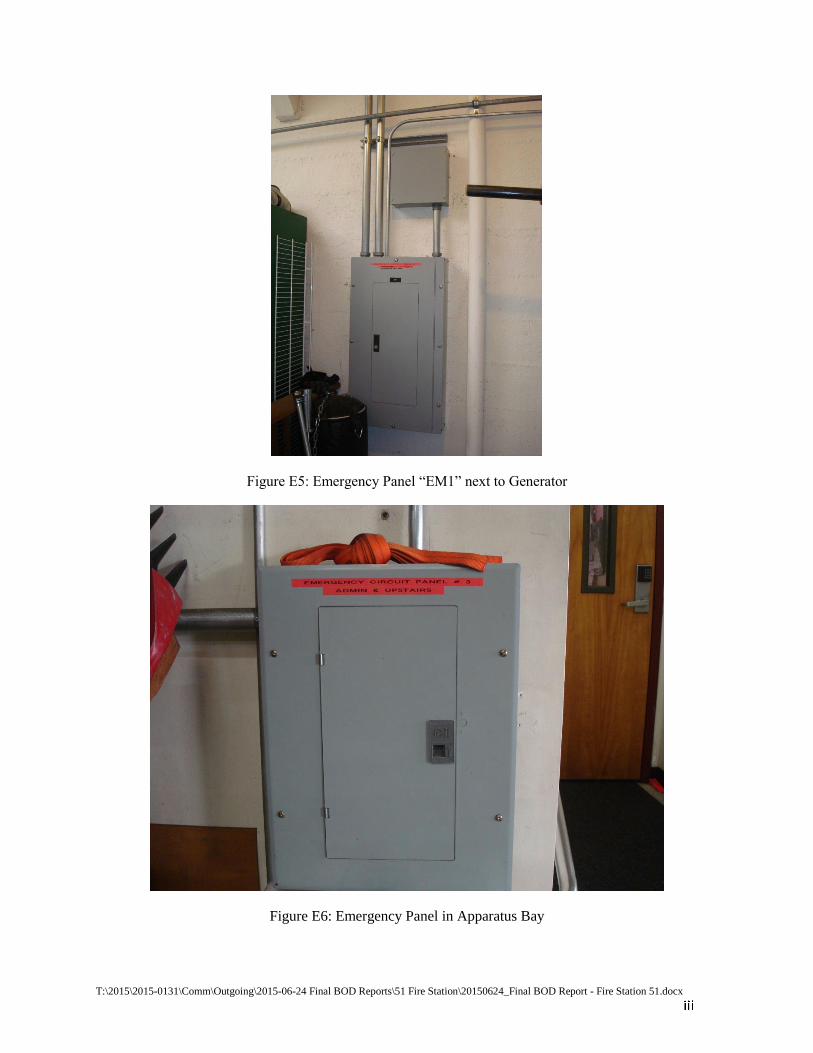
T:\2015\2015-0131\Comm\Outgoing\2015-06-24 Final BOD Reports\51 Fire Station\20150624_Final BOD Report - Fire Station 51.docx
Figure E5: Emergency Panel “EM1” next to Generator
Figure E6: Emergency Panel in Apparatus Bay

T:\2015\2015-0131\Comm\Outgoing\2015-06-24 Final BOD Reports\51 Fire Station\20150624_Final BOD Report - Fire Station 51.docx
Figure E7: Leaking Sewage Piping In Telecom Room

T:\2015\2015-0131\Comm\Outgoing\2015-06-24 Final BOD Reports\51 Fire Station\20150624_Final BOD Report - Fire Station 51.docx
Mechanical Appendix
Figure M1: Main Building Rooftop Package Unit and Rooftop Ductwork
Figure M2: Kitchen Commercial Type I Grease Hood

T:\2015\2015-0131\Comm\Outgoing\2015-06-24 Final BOD Reports\51 Fire Station\20150624_Final BOD Report - Fire Station 51.docx
Figure M3: Rooftop Package Unit on Lower roof Serving Offices
Figure M4: Force Air Unit Heater in Maintenance Bay

T:\2015\2015-0131\Comm\Outgoing\2015-06-24 Final BOD Reports\51 Fire Station\20150624_Final BOD Report - Fire Station 51.docx
Figure M5: Force Air Unit Heater in Apparatus Bay


5 0 5 1 7 t h S T R E E T, 2 n d F LO O R OA K L A N D , C A L I F O R N I A 9 4 6 1 2 O 5 1 0 . 2 0 8 . 9 4 0 0 W W W. M A RY M C G R AT H A R C H I T E C T S . C O M