Film Extrusion
44
A GUIDE TO POLYOLEFIN FILM EXTRUSION
-
Upload
khala1391gmailcom -
Category
Documents
-
view
158 -
download
11
description
film extrusion guide
Transcript of Film Extrusion

A GUIDE TO POLYOLEFINFILM EXTRUSION

1
Polyolefin films are used ina wide variety ofapplications. Clockwisefrom far left: LLDPE film;HMW-LDPE film; LDPE film.

2
Table of Contents Page
Introduction.............................................................................................................. 5Polyolefins are Thermoplastics Derived from Petrochemicals ................................. 6Molecular Structure and Composition Affect Properties and Processability ............. 6
Density .............................................................................................................. 7Molecular Weight .............................................................................................. 8Melt Viscosity .................................................................................................... 8Molecular Weight Distribution ............................................................................ 8Comonomers ..................................................................................................... 8Modifiers, Additives and Tie Layers ................................................................... 9
Equistar Works Closely with Processors ................................................................ 9Shipping and Handling Polyolefin Film Extrusion Resins ....................................... 9How Polyolefins are Made...................................................................................... 10 LDPE ................................................................................................................. 10
HDPE ................................................................................................................ 11LLDPE ............................................................................................................. 11PP ................................................................................................................... 11
The Film Extrusion Process .................................................................................. 12Materials Conditioning/Handling ........................................................................... 12
Materials Handling Equipment Design ............................................................ 12Blending with Colorants and Additives ............................................................ 14
Film Extrusion Equipment ..................................................................................... 14Extruder .......................................................................................................... 15
Coextrusion Systems .................................................................................. 15Cascade Extrusion Systems ........................................................................ 15
Hopper ............................................................................................................ 15Barrel .............................................................................................................. 17
Heaters ...................................................................................................... 17Thermocouples ........................................................................................... 17
Screw .............................................................................................................. 17Mixing Screws ............................................................................................ 18Barrier-Type Screws .................................................................................... 19
Screen Pack and Breaker Plate ...................................................................... 19Automatic Screen Changers ........................................................................ 20
Pressure Valves ............................................................................................. 21Adapter .......................................................................................................... 21
Melt Pumps ............................................................................................... 22Film Forming Equipment ............................................................................. 22Die ............................................................................................................ 22Transfer Piping/Adapters ............................................................................. 22Blown Film Dies ......................................................................................... 23
Rotating Dies ................................................................................................... 24Automatic Gauge Adjustment ................................................................. 24Coextrusion Blown Film Dies .................................................................. 24
Cast Film Dies ............................................................................................ 25Coextrusion Cast Film Dies .................................................................... 25
Cooling Systems .................................................................................................. 26Blown Film Cooling ........................................................................................ 26
3
External Air Rings ...................................................................................... 26Internal Bubble Cooling .............................................................................. 27Bubble Stabilizer ........................................................................................ 27
Cast Film Cooling .......................................................................................... 27Takeoff and Windup Equipment .......................................................................... 27
Blown Film Tower .......................................................................................... 27Guide Bars ................................................................................................ 28Collapsing Frames ..................................................................................... 28Nip Rolls ................................................................................................... 28Width Measurement ................................................................................... 28Gauge Measurement .................................................................................. 29Oscillating Haul-Off Units ............................................................................ 29Surface Treaters ........................................................................................ 29Guide Rolls ............................................................................................... 29Feed Roll Assembly ................................................................................... 29Optical Inspection System .......................................................................... 29
Film Winders ................................................................................................. 29Surface Winders ........................................................................................ 29Center Winders ......................................................................................... 30Surface/Center Assist Winders ................................................................... 30Gap Winding ............................................................................................ 30Taper Tensioning ....................................................................................... 30Automatic Roll Changers ............................................................................ 31Turret Winders .......................................................................................... 31Web Slitters .............................................................................................. 31Edge Cutting System ................................................................................. 31
Recycling Systems ........................................................................................ 31Controls ......................................................................................................... 31
Operation of a Blown Film Line ............................................................................ 32Start-Up Procedure for Film Line .................................................................... 32Accident Prevention ....................................................................................... 32
Cleaning the Extruder and Its Parts ...................................................................... 34How to Clean the Extruder .............................................................................. 34
Cleaning the Screw ..................................................................................... 34Cleaning the Barrel ..................................................................................... 34Cleaning the Adapter ................................................................................ 34Cleaning the Breaker Plate .......................................................................... 34Cleaning the Blown Film Die ........................................................................ 34Cleaning the Cast Film Die .......................................................................... 34
Optimizing Film Extrusion Process ...................................................................... 35Flat Film Forming ........................................................................................... 35
Table of Contents (Continued) Page

4
Table of Contents (Continued) Page
Temperatures ..................................................................................................... 35Screw Speed ...................................................................................................... 35Gauge Control .................................................................................................... 35Width .................................................................................................................. 35Cooling ................................................................................................... 35
Tubular Film Forming .................................................................................... 35Temperatures ..................................................................................................... 35Screw Speed ...................................................................................................... 35Blow-up Ratio ..................................................................................................... 35Cooling.................................................................................................... 36
Process Variables Controlling Property Improvement ....................................... 36Barrier ......................................................................................................... 36Clarity ......................................................................................................... 36Environmental Stress Crack Resistance ..................................................... 36Gauge Uniformity ........................................................................................ 36Gloss .......................................................................................................... 37Heat Sealability ........................................................................................... 37Stiffness ...................................................................................................... 37Strength ....................................................................................................... 37Toughness .................................................................................................. 37Slip ............................................................................................................. 37Shrink Wrap and Stretch Wrap ........................................................................... 37
Appendix 1: Metric Conversion Guide ................................................................ 38Appendix 2: Abbreviations ......................................................................................... 40Appendix 3: ASTM Test Methods Applicable to Film Extrusion .......................... 41Appendix 4: Trade Names for Products of Equistar Chemicals .......................... 42

5
INTRINTRINTRINTRINTRODUCTIONODUCTIONODUCTIONODUCTIONODUCTION
Polyolefins are the most widely used plastics for film extrusion. A Guide ToPolyolefin Film Extrusion contains general information concerning materials,methods and equipment for producing high quality polyolefin film products atoptimum production rates. Polyolefins that can be extruded as monolayer andmultilayer film include:
• Low density polyethylene (LDPE)
• Linear low density polyethylene (LLDPE)
• High density polyethylene (HDPE)
• Ethylene copolymers, such as ethylene vinyl acetate (EVA) and ethylenemethyl acrylate (EMA)
• Polypropylene, propylene copolymers (PP) and thermoplastic olefins (TPOs).
In general, the advantages gained with polyolefin films are ease of processing,light weight, good toughness and tear resistance, flexibility (even at low temper-atures), outstanding chemical resistance and relatively low cost compared withother plastics. The basic properties of polyolefins can be modified with a broadrange of chemical modifiers. Further, polyolefin-based films can be coextruded withvarious other polymers, including ethylene vinyl alcohol (EVOH), nylon, polyesterbarrier resins and adhesive tielayers, to produce multilayer films with special,high-performance properties. Major application areas for polyolefin films are:
• Packaging for food, textiles, consumer products, industrial products, medicalproducts, merchandise, among others
• Agriculture
• Construction
• Consumer products, including diaper backing, garment bags, household wrapand trash bags
• Materials handling, including stretch wrap and shrink wrap
This manual contains extensive information on polyolefin film extrusion;however, it makes no specific recommendations for the processing of EquistarChemicals resins for specific applications. For more detailed information, pleasecontact your Equistar polyethylene sales representative.

6
H H
C = C
H H
Figure 1. Ethylene monomermolecular structure
H H H H H H H H H H
C C C C C C C C C C
H H H H H H H H H H
Figure 2. Polyethylene molecularchain.
Figure 4. Polyethylene chain withside branches.
Figure 3. Polyethylene chain withside branches.
Polyolefins AreThermoplastics DerivedFrom Petrochemicals
Polyolefins are plastic resinspolymerized from petroleum-basedgases. The two principal gases areethylene and propylene. Ethylene isthe principal raw material formaking polyethylene (PE) andethylene copolymer resins; andpropylene is the main ingredient formaking polypropylene (PP) andpropylene copolymer resins.
Polyolefin resins are classifiedas thermoplastics, which meansthat they can be melted, solidifiedand melted again. This contrastswith thermoset resins which, oncemolded, cannot be reprocessed.
Most polyolefin resins for filmextrusion generally are used inpellet form. The pellets are about1/8 inch thick and 3/16 inch indiameter, usually somewhattranslucent and white in color.Polyolefin resins sometimes willcontain additives, such as thermalstabilizers. They also can becompounded with colorants,antistatic agents, slip and antiblockadditives, UV stabilizers, etc.
Molecular Structure andComposition Affect Propertiesand Processability
Three basic molecularproperties affect most of theproperties essential to high qualityfilm extrusion:
• Average Molecular Weight
• Molecular Weight Distribution
• Crystallinity or Density.
These molecular properties aredetermined by the materials usedto produce the polyolefins and theconditions under which they aremanufactured. The basic building
blocks for the gases from whichpolyolefins are derived are hydro-gen and carbon atoms. For polyeth-ylenes, these atoms are combinedto form the ethylene monomer,C
2H
4, i.e., two carbon atoms and
four hydrogen atoms (see Figure1). In the polymerization process,the double bond connecting thecarbon atoms is broken. Under theright conditions, these bondsreform with other ethylene mol-ecules to form long molecularchains (Figure 2). The resultingproduct is polyethylene.
For polypropylene, thehydrogen and carbon atoms arecombined to form the propylenemonomer, CH
3CH=CH
2, which has
three carbon atoms and sixhydrogen atoms (Figure 3). Thethird carbon atom remains pendantand protrudes from the spiralingbackbone chain.
Ethylene copolymers, such asEVA and EMA, are made by thepolymerization of ethylene unitswith randomly distributedcomonomer groups, such as vinylacetate (VA) and methyl acrylate(MA).
The polymerization ofmonomers creates a mixture ofmolecular chains of varyinglengths. Some are short, whileothers are enormously long,containing several hundredthousand monomer units. Forpolyethylene, the ethylene chainshave numerous side branches. Forevery 100 ethylene units in themolecular chain, there are aboutone to 10 short or long branches.The branches radiate in threedimensions (Figure 4).
Chain branching affects manypolymer properties includingdensity, hardness, flexibility andtransparency, to name a few. Chainbranches also become points in themolecular network where oxidationmay occur. In some processingtechniques where high tempera-tures are reached, oxidation canadversely affect the polymer’sproperties.

7
Figure 5. Crystalline (A) andamorphous (B) regions inpolyolefin.
DensityPolyolefin resins have a
mixture of crystalline and amor-phous areas. Molecular chains incrystalline areas are arrangedsomewhat parallel to each other. Inamorphous areas, they are ran-domly arranged. This mixture ofcrystalline and amorphous regions(Figure 5) is essential to theformation of good film products. Atotally amorphous polyolefin wouldbe rubber-like and have poorphysical properties; a totallycrystalline polymer would be veryhard and brittle.
For homopolymer polyethyl-enes, the higher the resin density,the higher the degree of crystallin-ity. High density PE resins havemolecular chains with com-paratively few side chain branches.This allows the chains to packmore closely together. The result iscrystallinity up to 85%. Low densityPE resins generally have crystallin-ity from 35 to 55%. Linear lowdensity PE resins have crystallinityfrom 35 to 60%. Polypropyleneresins are highly crystalline, butthey are not very dense.
• LLDPE resins densities rangefrom 0.900 to 0.939 grams percubic centimeter (g/cc)
• LDPE resins range from 0.916to 0.925 g/cc
• MDPE (medium density) resinsrange from 0.926-0.940 g/cc
• HDPE resins range from 0.941to 0.965 g/cc
• PP resins range from 0.890 to0.905 g/cc
• The densities of EVA and EMAcopolymers are functions of theproportion of comonomerincorporated into the resin; ascomonomer increases, densityincreases, but crystallinitydecreases.
Table 1: General Guide to the Effects of LDPE Resin PhysicalProperties on their Mechanical Properties and Processing.
As Melt Index As DensityCharacteristic Increases Increases
Chemical Resistance Remains Same Increases
Clarity Increases Increases
Elongation at Rupture Decreases Decreases
Extrusion Speed Remains Same Increases (faster solidification)
Film Drawdown Increases Increases
Film Impact Strength (toughness) Decreases Decreases
Flexibility Decreases Remains Same
Gloss Increases Remains Same
Heat Resistance Decreases Increases(softening point)
Impermeability to Gases/Liquids Remains Same Increases
Low Temperature Flexibiity Decreases Decreases
Melt Viscosity Decreases Increases
Mechanical Flex Life Decreases Decreases
Resistance to Film Blocking Decreases Increases
Stress Cracking Resistance Decreases Decreases
Tensile Strength at Rupture Decreases Increases
Higher density, in turn,influences numerous properties(Table 1). With increasing density,some properties increase.However, increased density alsoresults in a reduction of someproperties, e.g., stress crackingresistance and low temperaturetoughness.

8
Molecular WeightAtoms of different elements,
such as carbon, hydrogen, etc.,have different atomic weights. Forcarbon, the atomic weight is 12,and for hydrogen it is 1. Thus, themolecular weight of the ethyleneunit is the sum of the weight of itssix atoms (2 carbon + 4 hydrogen)or 28.
Every polyolefin resin consistsof a mixture of large and smallchains, i.e., chains of high and lowmolecular weights. The molecularweight of the polymer chain gener-ally is in the thousands. Theaverage of these is called, quiteappropriately, the average molecu-lar weight.
As average molecular weightincreases, resin toughness in-creases. The same holds true fortensile strength and environmentalstress cracking resistance (crack-ing brought on when film is sub-jected to stresses in the presenceof liquids such as solvents, oils,detergents, etc.).
Melt ViscosityMelt viscosity generally is
expressed for polyethylene resinsby their melt indices (tested understandard conditions of temperatureand pressure). Melt index (MI) isinversely related to the resin’saverage molecular weight: asaverage molecular weight in-creases, MI decreases. Generally,a polyolefin resin with high molecu-lar weight has a low MI, and viceversa.
Melt viscosity is an extremelyimportant property since it affectsthe flow of the molten polymer. Theresin’s flow when melted increaseswith increasing MI. Therefore,polyolefins with lower MI requirehigher extrusion temperatures. Itshould be remembered that pres-sure can influence flow properties.Two resins may have the same MI,but different high pressure flowproperties. Therefore, MI (Table 2)must be used in conjunction withother yardsticks, such as molecular
Table 2: Polyolefin Film ExtrusionResins
Resin Melt Index Rangesg/10 min.*
LLDPE <1 to 2 LDPE <1 to 5 HDPE <1 to 10 EVA <1 to 10 PP 1 to 10 MFR **
* Melt Index describes the flow behaviorof a resin at a specified test temperature(190°C, 374°F) and under a specifiedweight (2,160g). Resins with a highermelt index flow more easily in the hot,molten state than those with a lower meltindex.** Melt Flow Rate (MFR), rather than MI, isused to describe the flow behavior ofpolypropylene resins. MFR is tested at ahigher specified temperature (446°F,230°C), but under the same specified load(2,160g) as polyethylene.
Figure 6. Schematic representationof molecular weight distribution.
weight distribution, to measure flowand other properties of resins.Generally, polyolefin film extrusionresins are characterized as havingmedium, high and very highviscosity.
Molecular Weight DistributionThe relative distribution of
large, medium and small molecularchains in a polyolefin resin isimportant to its properties. Whenthe distribution consists of chainsclose to the average length, theresin is said to have a “narrowmolecular weight distribution”(Figure 6). “Broad molecularweight distribution” polyolefins arethose resins with a wider variety ofchain lengths. In general, resinswith narrow molecular weightdistributions have greater stresscracking resistance and betteroptical properties. Resins withbroad molecular weight distribu-tions generally have greater impactstrength and greater ease ofprocessing.
ComonomersPolyolefins made with one
basic type of monomer are calledhomopolymers. There are,however, many polyolefins whichconsist of two or more monomers –each called a comonomer – andthese combinations are calledcopolymers. Many film extrusiongrades of LLDPE, LDPE, HDPEand PP are made withcomonomers. These side chaingroups provide specific propertyimprovements.
The comonomers used mostoften with LLDPE and HDPE arecollectively called alpha olefins.They include butene, hexene andothers. Other comonomers usedwith ethylene to make filmextrusion grades are MA to makeEMA copolymers, and VA toproduce EVA copolymers.
The addition of small amountsof VA to polyethylene results in aresin which extrudes similarly to apolyethylene homopolymer but has
the additional properties ofincreased toughness, lowerstiffness and potentially higherclarity. A wide range of properties ispossible, depending upon theproportion of VA incorporated andthe synthesis conditions used tomake the modified resins.
EMA copolymers offer betterheat stability during film extrusionthan EVA resins. This property is ofparticular interest when polyolefins

9
are coextruded with resins ofhigher melting temperatures. EMAsoffer better low temperature meltingproperties and good adhesion to awide variety of substrates.
Ethylene is the primarycomonomer used with PP. PPrandom copolymers havepropylene backbones containingrandom ethylene groups. Impactcopolymers have propylenebackbones containing groups ofethylene molecules.
Modifiers, Additives andTie-Layers
Numerous chemical modifiersand additives are compounded withpolyolefin film extrusion resins. Insome grades, the chemicalmodifiers are added during resinmanufacture. These includethermal stabilizers, antistatic agentsand slip/antiblock agents. (SeeTable 3).
Tie-layers are polyolefin-basedresins which are used to bond apolyolefin to other polar materialsduring coextrusion, coating orlamination. Tie-layers arespecifically designed for use withsuch polar barrier materials asnylon (PA), polyester (PET),polyvinylidene chloride (PVdC) andethylene vinyl alcohol (EVOH).
Table 3: Typical Additives Used withPolyolefin Extrusion Coating Resins.
Additive Primary Benefit
Antistats Static buildupresistance
Fragrances Add attractivecolor, e.g. floral
Nucleating Faster film Agents processing
Organic Improved film Peroxides processing
Processing Aids Reduce meltfracturing
Slip/Antiblock Improved Agents film-to-filmslip
Thermal Resistance to Stabilizers oxidation
during pro-cessing andend use life
UV Stabilizers Resistance toeffects ofsunlight
Figure 7: Diagram of the polyethylene production process from liquified petroleum gas (LPG) to solid polyethylenepellets.
Equistar Works Closely withProcessors
Equistar Chemicals offers awide range of polyolefin resins forfilm extrusion, includingPetrothene® LDPE, LLDPE, HDPEand PP, Alathon® HDPE andUltrathene® EVA copolymers.These resins also are tailored tomeet the requirements of manyapplications. Some typical specialtygrades are:
• High molecular weight LDPE
• High stress crack resistantHDPE
• Medium molecular weightHDPE
• High drawdown LDPE
• High moisture barrier HDPE
• High clarity LDPE
• Heat-seal EVA
Shipping and Handling PolyolefinFilm Extrusion Resins
It is extremely important to keeppolyolefin resins clean. Contami-nated resins can produce poorproducts. Polyolefin resins areshipped to processors in hoppercars, hopper trucks, 1000- and1500-pound polyethylene-linedcorrugated boxes and 50-pound

10
plastic bags. Strict quality controlthroughout resin manufacture andsubsequent handling, right throughdelivery to the processor, ensurethe cleanliness of the products.
When bulk containers aredelivered, the processor must useclean, efficient procedures forunloading the resin. Maintenanceof the in-plant materials handlingsystem also is essential. Whenbags and boxes are used, specialcare also is a must in opening thecontainers, as well as coveringthem as they are unloaded andused.
Reground resin, whether as ablend or as is, should also besubject to stringent precautions tokeep it free of contamination.Whenever possible, the regrindshould be used as it is generated.When this is not possible, the scrapshould be collected in a closedsystem and recycled with the sameprecautions taken as for virginresin.
How Polyolefins are MadeHigh-purity ethylene, propylene,
butene and hexene gases are thebasic feedstocks for makingpolyolefins (Figure 7). These gasescan be a petroleum refinerybyproduct or they can be extractedfrom ethane-propane liquefied gasmixes coming through pipelinesfrom a gas field. High efficiency inthe ethane/propane cracking andpurification results in very pureethylene and propylene (Figure 8).This high purity is one of the keyreasons that Equistar’s polyolefinresins excel among commerciallyavailable LDPE, LLDPE, HDPE, PPand ethylene copolymers.
LDPETo make LDPE resins (Figure
9), Equistar uses high pressure,high temperature polymerizationreactors. Ethylene gas, pumpedinto the reactors, is activated by acatalyst and polymerizes intopolyethylene. The LDPE formedflows to a separator where unused Figure 9: Process diagaram for LDPE production in an autoclave reactor.
Figure 8: Top, Polypropylene unit at Equistar's Morris, IL, plant; Bottom,
HDPE unit at Equistar's LaPorte, TX, plant.

11
gas is removed. Next, the LDPEgoes to a compounding extruderwhere additives are added prior topelletizing.
HDPEThere are two basic processes
for making HDPE (Figure 10): theparticle form slurry process (themost widely used method), and thegas phase process. The flow ofthese processes is quite similar tothe LLDPE process except thatrelatively low pressure, lowtemperature reactors are used.
LLDPEEquistar uses a gas-phase
process for making LLDPE (Figure11). The LLDPE process is quitedifferent from the WIDE process,but similar to some HDPE pro-cesses. The major differences fromthe LDPE process are that lowpressure, low temperature polymer-ization reactors are used and thatthe ethylene is copolymerized withbutene or hexene comonomers inthe reactor. A final distinction is thatthe polymer exits the reactor asgranules that are then compoundedwith additives in an extruder andpelletized. Certain HDPE resinsalso can be made in these reac-tors.
PPFor making PP, Equistar uses a
vertical, stirred fluidized-bed,gas-phase reactor (Figure 12).Equistar was the first polypropylenesupplier in the United States to usegas-phase PIP technology. Thisprocess is more energy efficientand produces a more uniformproduct than earlier polypropylenemanufacturing processes.
Figure 10: Process diagram for HDPE production in a particle-form reactor.
Figure 11: Process diagram for LLDPE or HDPE production in a gas-phasereactor.

12
The Film Extrusion Process
There are three basic stages inthe overall film extrusion process:
1. Materials Conditioning/Handling2. Film Extrusion3. Film Takeoff
Materials Conditioning/HandlingAt its resin manufacturing
plants, Equistar has extensivesystems, such as filters, cyclones,elutriators, etc. to prevent resincontamination during production,storage, loading and shipment.Since polyolefin resins arenon-hygroscopic (they absorbvirtually no water), they do notrequire drying prior to extrusion.However, precautions should betaken to ensure the cleanliness ofthe polyolefin pellets as they arehandled at the processor’sfacilities.
One way to decrease problemsin processing polyolefin resin is toprevent contaminants from entering
Figure 12: Process diagram for PP production in a vertical, stirred fluidizedbed, gas-phase reactor.
transfer systems. Whenever apolyolefin resin is moved by acurrent of air through transferpiping, the possibility ofcontamination exists. Dust, fines,streamers and angel hair can begenerated and plug filters or othercomponents of the transfer systemthat results in starvation of theextruder. Occasionally, largeclumps of angel hair or streamersmay accumulate in a silo and plugthe exit port. All of these problemscan result in extruder downtime,excessive scrap and the time andwork force costs of cleaning silos,transfer lines and filters.
Many transfer systems consistof smooth bore piping that conveysthe resin from hopper cars tostorage silos or holding bins. Sometransfer systems may include longradius bends. A polyolefin pelletconveyed by forced air throughsuch a transfer line travels at a veryhigh velocity. As the pellet comes incontact with the smooth pipe wall, itslides and slows down due to
friction. The friction, in turn, createssufficient heat to raise the pellet’ssurface temperature to the resin’smelting point. As this happens, asmall deposit of molten polyolefin isleft on the pipe wall. This depositsolidifies almost instantly. Overtime,these deposits buildup and arecalled “angel hair” when theyslough off and are found mixed withthe pellets.
As the pellets continuouslycome in contact with the pipe wall,such as along the curved outsidesurface of a long radius bend, thedeposits of polyolefin becomealmost continuous and longstreamers are formed. Eventually,the angel hair and streamers aredislodged from the pipe wall andfind their way into the extrusionprocess, the storage silo or thetransfer filters. The size andnumber of streamers formedincrease with increases inconveying air temperature andvelocity and are also greater withsmooth bore piping than with otherkinds of handling systems.
Materials Handling EquipmentDesign
Since smooth piping is aleading contributor to angel hairand streamers, the logical solutionis to roughen the interior wall of thepiping. This roughness will causethe pellets to tumble instead ofslide along the pipe, thusdecreasing streamer formation.However, as a rapidly movingpolyolefin pellet comes in contactwith an extremely rough surface,small particles break oft, and finesor dust are created.
Two specific finishes formaterials handling piping haveproven to be the best performersand give the longest life; the first isa sand blasted finish of 600 to 700RMS roughness. This finish isprobably the easiest to obtain;however, until they becomerounded with use, the initial sharpedges of the finish will result in dustand fines.
The other finish is achieved by
13
shot blasting using a #55 shot with55-60 Rockwell hardness toproduce a 900 RMS roughness.Variations of this finish arecommonly known as “hammerfinished” surfaces. The shotblasting allows deeper penetrationand increases hardness, which inturn, leads to longer surface life.The rounded edges obtainedminimize the initial problemsencountered with dust and fines.They also reduce metalcontamination possibilitiesassociated with the sandblastedfinish.
Whenever a new transfersystem is installed or when aportion of an existing system isreplaced, the interior surfacesshould be treated either by sand orshot blasting. The initial cost is faroutweighed by the prevention offuture problems.
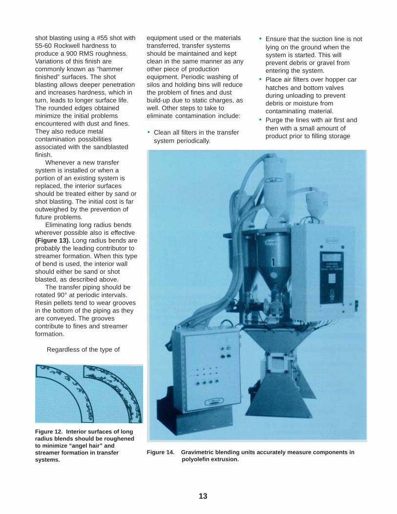
Eliminating long radius bendswherever possible also is effective(Figure 13). Long radius bends areprobably the leading contributor tostreamer formation. When this typeof bend is used, the interior wallshould either be sand or shotblasted, as described above.
The transfer piping should berotated 90° at periodic intervals.Resin pellets tend to wear groovesin the bottom of the piping as theyare conveyed. The groovescontribute to fines and streamerformation.
Regardless of the type of
Figure 12. Interior surfaces of longradius blends should be roughenedto minimize “angel hair” andstreamer formation in transfersystems.
Figure 14. Gravimetric blending units accurately measure components inpolyolefin extrusion.
equipment used or the materialstransferred, transfer systemsshould be maintained and keptclean in the same manner as anyother piece of productionequipment. Periodic washing ofsilos and holding bins will reducethe problem of fines and dustbuild-up due to static charges, aswell. Other steps to take toeliminate contamination include:
• Clean all filters in the transfersystem periodically.
• Ensure that the suction line is notlying on the ground when thesystem is started. This willprevent debris or gravel fromentering the system.
• Place air filters over hopper carhatches and bottom valvesduring unloading to preventdebris or moisture fromcontaminating material.
• Purge the lines with air first andthen with a small amount ofproduct prior to filling storage

14
silos or bins. Let blowers runseveral minutes after unloadingto clean lines. This reduces thechance of cross-contamination ofproduct.
Information regarding transfersystems and interior finishes canbe obtained from most suppliers ofmaterials handling equipment.Complete systems can be suppliedwhich, when properly maintained,will efficiently convey con-tamination-free product. Equistarhas also published a bookletentitled, “Handling and Storage ofEquistar Polyethylene andSpecialty Polymers" which dealswith polymer unloading and con-veying systems. For a copy, contactyour Equistar polyethylene salesrepresentative.
Blending With Colorants andAdditives
In-line blending units consist ofmultiple hoppers which are feddifferent resin compoundingredients (Figure 14). Colorant oradditive concentrates, regrind andbase resin are combined usingeither volumetric or weight-lossfeeding (gravimetric) techniques;the latter is usually more accurate.Microprocessor controls determineand monitor the amounts ofmaterial fed into a mixing chamber.Recipes can be stored in thecontrol unit for instant recall.
Central blending units also canbe used when much higherthroughputs are needed thanpossible with on line blenders.Transfer to the extruder is by acentral vacuum loading system.
Film Extrusion Equipment
Two basic methods are usedfor making polyolefin film: cast filmextrusion and blown film extrusion.In both methods, the resin is firstmelted by subjecting it to heat andpressure inside the barrel of anextruder and finally forcing the meltthrough a narrow slit in a die. The
Table 4: General Comparison of Cast and Blown Films
Characteristics Blown Film Cast Film
Clarity Less Greater
Edge TrimWaste Less Greater
Gauge Control Less Greater
Capital Investment Less Greater
Output/Efficiency Less Greater
Transverse Strength Greater Less
Width Flexibility Greater Less
Figure 15. The extruder consists of a resin feeding hopper, a heated barrel,a constant rotating screw, a manual screen changer, a dieadapter and a base.
Courtesy of Battenfeld Gloucester Engineering Co., Inc.
15
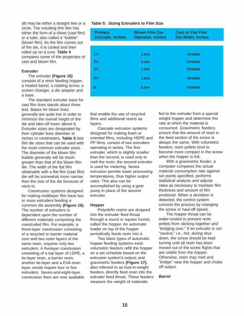
slit may be either a straight line or acircle. The resulting thin film haseither the form of a sheet (cast film)or a tube, also called a “bubble”(blown film). As the film comes outof the die, it is cooled and thenrolled up on a core. Table 4compares some of the properties ofcast and blown film.
ExtruderThe extruder (Figure 15)
consists of a resin feeding hopper,a heated barrel, a rotating screw, ascreen changer, a die adapter anda base.
The standard extruder base forcast film lines stands about threefeet. Bases for blown linesgenerally are quite low in order tominimize the overall height of thedie and take-off tower above it.Extruder sizes are designated bytheir cylinder bore diameter ininches or centimeters. Table 5 listsfilm die sizes that can be used withthe most common extruder sizes.The diameter of the blown filmbubble generally will be muchgreater than that of the blown filmdie. The width of the flat filmobtainable with a flat film (cast film)die will be somewhat more narrowthan the size of the die because ofneck-in.
Coextrusion systems designedfor making multilayer film have twoor more extruders feeding acommon die assembly (Figure 16).The number of extruders isdependent upon the number ofdifferent materials comprising thecoextruded film. For example, athree-layer coextrusion consistingof a recycled or barrier materialcore and two outer layers of thesame resin, requires only twoextruders. A fivelayer coextrusionconsisting of a top layer of LDPE, atie-layer resin, a barrier resin,another tie-layer and a EVA resinlayer, would require four or fiveextruders. Seven-and-eight-layercoextrusion lines are now available
Table 5: Sizing Extruders to Film Size
Primary Blown Film Die Cast or Flat FilmExtruder, Inches Diameter, Inches Die Width, Inches
1½ Less Greater
2½ Less Greater
3½ Less Greater
4½ Less Greater
6 Less Greater
that enable the use of recycledfilms and additional resins aslayers.
Cascade extrusion systemsdesigned for making foam ororiented films, including HDPE andPP films, consist of two extrudersoperating in series. The firstextruder, which is slightly smallerthan the second, is used only tomelt the resin; the second extruderis used for metering. Seriesextrusion permits lower processingtemperatures, thus higher outputrates. This also can beaccomplished by using a gearpump in place of the secondextruder.
HopperPolyolefin resins are dropped
into the extruder feed throatthrough a round or square funnel,called the hopper. An automaticloader on top of the hopperperiodically feeds resin into it.
Two basic types of automatichopper feeding systems exist:volumetric feeders refill the hopperon a set schedule based on theextrusion system’s output; andgravimetric feeders (Figure 17),also referred to as loss-in-weightfeeders, directly feed resin into theextruder feed throat. These feedersmeasure the weight of materials
fed to the extruder from a specialweight hopper and determine therate at which the material isconsumed. Gravimetric feedersensure that the amount of resin inthe feed section of the screw isalways the same. With volumetricfeeders, resin pellets tend tobecome more compact in the screwwhen the hopper is full.
With a gravimetric feeder, acomputer compares the actualmaterial consumption rate againstset points specified, performsstatistical analysis and adjustsrates as necessary to maintain filmthickness and amount of filmproduced. When a deviation isdetected, the control systemcorrects the process by changingthe screw or haul-off speed.
The hopper throat can bewater-cooled to prevent resinpellets from sticking together and“bridging over.” If an extruder is run“neutral,” i.e., hot, during shutdown, the screw should be keptturning until all resin has beenmoved out of the screw flights thatare visible from the hopper.Otherwise, resin may melt and“bridge” near the hopper and chokeoff output.
Barrel

16
Courtesy of Battenfeld Gloucester Engineering Co., Inc.
Figure 16. Coextrusion systems designed for making multilayer film have two or moreextruders feeding a common die assembly.

17
Figure 18. For HMW-HDPE and LLDPE film extrusion, barrels are designedwith up to 12 helical grooves.
Most barrels have smoothbores. However, for makingHMW-HDPE and LLDPE film athigh throughput rates, the feedsection of the barrel may bewatercooled and have as many as12 helical grooves (Figure 18).This configuration permits low meltindex HMW-HDPE, HMW-LDPEand LLDPE resins to be processedat high extrusion rates. Barrels withhigh wear-resistant metal liners,such as tungsten carbide, generallywear better than extruder screws.
HeatersFor fast extruder start-up,
barrel heating is necessary andusually done by electrical barrelheating bands. They respondrapidly, are easy to adjust andrequire a minimum of maintenance.The heater bands are distributedalong the barrel length in what arecalled zones. Generally, the barrelis divided into three to six zones.Blowers in each zone decrease theheat when necessary and rapidlycool the barrel when the extruder isto be shut down. Water-cooledzones also are used by somemanufacturers for faster heattransfer.
ThermocouplesThermocouples are inserted
deep into the barrel wall, and insome cases even into the melt, tomonitor processing temperature.Signals from the thermocouplesactivate temperature controllingmechanisms to regulate the heaterbands and cooling devices.Regular maintenance checksshould be made to detectloose-fitting, broken or damagedthermocouples or wires.
ScrewA motor-driven screw rotates
within the hardened liner of thebarrel (Figure 19). Screw speedstypically are in the range of 50 to250 rpm. As the screw rotates, thescrew flights force the resin in thescrew channel forward, the screwchannels become more shallowand the resin is heated,
Figure 17. Gravimetric feeder/blender with eight ingredient modules.
Courtesy of K-Tron Vertech Inc.

18
compressed, melted and mixed.The general purpose extrusionscrew normally is barrier-f lightedand square-pitched and has fourbasic sections, as shown by Table6. Good mixing of the melted resinis essential for obtaining high clarityfilm with no defects or blemishes.Static mixers can be added beforethe die to maximize mixing. Somefilm defects that can occur include:
• Fisheyes – elliptically shapedspots, with the long axis in themachine direction
• Oxidized Particles – yellow-brown specks
• Gels – round or oblong,symmetrical, clear spots, so hardthey can be felt
• Arrowheads – minute linesmeeting at a rounded angle
• Applesauce or Melt Fracture –rough, wavy appearance
• Pinholes – tiny holes
A long, properly designedscrew makes for better melting andmixing of the resin, as well asbetter film appearance, closergauge tolerance and increasedproduction rate. Screws are speci-fied by their length to-diameter(UD) ratio and compression ratio.Ideally, the screw should be at least24 times, preferably 28 to 30 times,as long as its diameter. A larger UDratio allows enhanced mixing. Thecompression ratio is the ratio of thechannel volume of one screw flightin the feed section to that of onescrew flight in the metering section.Thus, a typical screw for polyolefinfilm extrusion should have a 24:1 to30:1 L/D ratio and a 2.5 to 3.51compression ratio.
Extruder screws can be coredfor water cooling. Some recentdesigns do not utilize this methodbut most employ various types ofmixing devices. A cool screw canimprove resin mixing, but usuallyreduces output at a given screwspeed. Screw temperature can beautomatically maintained between80° and 180°F (25° and 80°C) by atemperature controller which
Courtesy of Brampton Engineering, Inc.
Figure 19. Schematic of film extrusion screw.
adjusts the amount of water flowingthrough the screw. If a screwoverheats, it loses much of itspumping capacity.
Mixing ScrewsFor some polyolefins, additional
mixing is required of the screw(Table 7). Mixing screws have thesame three sections as generalpurpose screws, but they also have
Table 6: Functions of a General Purpose Polyethylene Extrusion Screw
Channel Section Depth Functions
Feed Deep, constant Move cool resin forward
Compression/Transition Decreasing Compress, melt and mixresin. Also, force air ack tofeed section
Metering Shallow, constant Create sufficient backpressure to uniformly meltresin and meter it throughdie at a constant feed ratewith minimum surging.
Mixing Varied Mix the resin(s). May havemore than one section.Usually located in themetering section of thescrew.
a fourth mixing section. The mixingsection can have variousconfigurations designed fordispersive mixing. Another designgives the screw two mixingsections: one at the end of themetering section and one near theend of the compression section.
Barrier-Type ScrewsAlso designed for improved
mixing, barrier-type screws
19
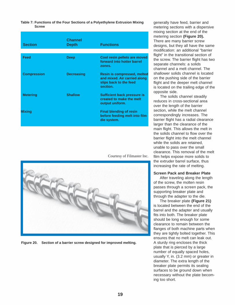
Table 7: Functions of the Four Sections of a Polyethylene Extrusion MixingScrew
Channel Section Depth Functions
Feed Deep Cool resin pellets are movedforward into hotter barrelzones.
Compression Decreasing Resin is compressed, meltedand mixed. Air carried alongslips back to the feedsection.
Metering Shallow Sufficient back pressure iscreated to make the meltoutput uniform.
Mixing Final blending of resinbefore feeding melt into filmdie system.
generally have feed, barrier andmetering sections with a dispersivemixing section at the end of themetering section (Figure 20).There are many barrier screwdesigns, but they all have the samemodification: an additional “barrierflight” in the transitional section ofthe screw. The barrier flight has twoseparate channels: a solidschannel and a melt channel. Theshallower solids channel is locatedon the pushing side of the barrierflight and the deeper melt channelis located on the trailing edge of theopposite side.
The solids channel steadilyreduces in cross-sectional areaover the length of the barriersection, while the melt channelcorrespondingly increases. Thebarrier flight has a radial clearancelarger than the clearance of themain flight. This allows the melt inthe solids channel to flow over thebarrier flight into the melt channelwhile the solids are retained,unable to pass over the smallclearance. This removal of the meltfilm helps expose more solids tothe extruder barrel surface, thusincreasing the rate of melting.
Screen Pack and Breaker PlateAfter traveling along the length
of the screw, the molten resinpasses through a screen pack, thesupporting breaker plate andthrough the adapter to the die.
The breaker plate (Figure 21)is located between the end of thebarrel and the adapter and usuallyfits into both. The breaker plateshould be long enough for someclearance to remain between theflanges of both machine parts whenthey are tightly bolted together. Thisensures that no melt can leak out.A sturdy ring encloses the thickplate that is pierced by a largenumber of equally spaced holes,usually Y, in. (3.2 mm) or greater indiameter. The extra length of thebreaker plate permits its sealingsurfaces to be ground down whennecessary without the plate becom-ing too short.
Figure 20. Section of a barrier screw designed for improved melting.
Courtesy of Filmaster Inc.

20
The functions of a breakerplate are to:
• Support the screen pack
• Reinforce the screen pack’saction
• Develop back pressure
• Straighten out the spiral flow ofthe melt caused by the screw
• Serve as a melt seal betweenthe barrel and the adapter(which a loose breaker platecannot do)
• Help align the barrel andadapter.
The screen pack (Figure 22),located in the breaker plate,consists of a number of stainlesssteel screens to filter out foreignmatter that may have contaminatedthe resin in the hopper. The screenpack also can help increase backpressure in the barrel andincreases mixing.
Automatic screen changershave either a continuous screenband or rotary units that indexwhen exposed sections becomeclogged. The indexing occurswithout interrupting the melt flow.Manual screen changers (Figure23) are the most common in theindustry. Hydraulic screen changersare also used, predominately onlarger machines.
Back pressure in the screwmetering zone may be increased byusing a screen pack consisting ofmany fine screens. Higher backpressure at a given screw speedimproves film quality, although itmay reduce output. Thetemperature of the melt can beraised slightly by using a muchheavier screen pack (more and/orfiner screens) which, by increasingthe pressure, generates additionalfriction heat. The use of a heavyscreen pack can result in improvedfilm quality. Excessive pressures(usually, 2000 to 3000 psi abovenormal operating pressure) mayindicate that screen packs need tobe changed.
Figure 22. Schematic of a screen pack andbreaker plate assembly.
Figure 23. A manual screen changer is the most com-monly found type in the industry.
Courtesy of ADDEX, Inc.
Figure 21. Breaker plate (left) and screen pack.

21
Pressure ValvesPressure valves (Figure 24)
provide a method of varyinginternal pressures. Thesepressures have a powerful effecton the melt temperature. Pressurevalves provide good control andhandle a function that wouldotherwise require variations in thedie design and/or screen packarrangement. Two types ofpressure valves are used:
1. The internal pressure valve is amovable screw that can beadjusted forward or backwardto increase or decreasepressure. Moving the screwvaries the size of the openingbetween the end of the screwand the breaker plate andadapter.
2. External pressure valves makeuse of some type of pinarrangement that varies thesize of the opening at theextruder’s adapter, therebyvarying pressure.
AdapterThe adapter guides the resin
melt from the barrel to the die asquickly and uniformly as possible.Uneven flow would mean deadareas where some of the meltcould be held back, excessivelyheated and decomposedchemically. A hinged collargenerally serves to attach theadapter tightly to the barrel.Adapter heaters keep the adapterat a specified temperature.
Maintaining the temperature ofthe melt when it leaves the extruderto be formed into film is veryimportant. Melt temperatures canbe checked by using athermocouple that extends throughthe adapter or die wall and into themelt stream. Automatic,motor-driven thermocouplesystems move across the meltstream and enable the melttemperature across it to bemonitored. Figure 25. Blown Film Die.
Courtesy of Brampton Engineering, Inc.
Figure 24. Schematic of a pressure valve.

22
Melt PumpsMelt pumps, also called gear
pumps, can be attached betweenthe end of the extruder and the dieto greatly increase film quality.These units can deliver a stable,surge-free, controlled volume ofmelt output, thus improving gaugeuniformity. The melt pump also mayenable faster extruder speeds.
Film Forming Equipment
DieThe film extrusion die (Figure
25) is attached to the adapter. Agood die design ensures smoothand complete melt flow, thuspreventing resin degradation fromoverheating. The functions of thedie are to:
1. Force the melt into a formapproaching its final shape.
2. Maintain the melt at a constanttemperature.
3. Meter the melt at a constantpressure and rate to the dieland for uniform film gauge,with allowance for gaugereduction.
The die consists of a body,mandrel or pin, heaters and lands.The die lands decrease the speedof the melt flow and build-up backpressure in the die and adapter. Ifthe land length is too short, themelt flow out of the die may beuneven because of nonuniformpressure around the circumferenceof the die. The die mandrel can beadjusted to change the die openingin order to control gauge uniformity.Most film extrusion dies are dividedinto heating zones and die heatersare automatically controlled.
Transfer Piping/AdaptersThe melt coming from the
extruder to a multilayer die passesthrough piping (Figure 26) whichmust be kept as short in length aspossible. However, any largereduction in its diameter should beminimized to prevent the pipingfrom affecting the melt passingthrough it.
Figure 27. Schematic of melt entering the die from five extruders in blownfilm coextrusion.
Courtesy of Battenfeld Gloucester Engineering Co. Inc.
Figure 26. Film extrusion involves the melt passing through transfer piping.The length of this piping must be as short as possible.
Courtesy of Battenfeld Gloucester Engineering Co. Inc.

23
Blown Film DiesIn blown film extrusion, the melt
enters the round die either throughthe bottom or the side (Figure 27).The melt is forced through spiralgrooves around the surface of amandrel inside the die andextruded through the circular dieopening in the form of athick-walled tube. Melt distributioncan be improved by lengtheningand/or increasing the number of thespiral grooves.
The tube, while still in themolten state, is expanded into along “bubble” of desired diameterand correspondingly decreasedthickness. This expansion resultsfrom the volume of air inside thebubble, which is introduced into thetube through the center of themandrel.
Blown film dies have a numberof circular heating zones. Dietemperature should be the same asmelt temperature.
Most blown film dies forpolyethylenes are positionedvertically to push the tube upward.However, there are dies whichextrude downward.
The gap between the mandreland the die ring ranges from 25 to120 mil (0.5 to 3 mm). In somedies, this opening can be changedby moving the mandrel lengthwisein the die. Most dies require achange in mandrels in order toadjust the die gap opening. Thisadjustment changes the extrudedtube thickness. A wider ringopening increases output slightly,but due to uneven flow, it maymake gauge and frost line controlmore difficult. It also tends topromote film snap-off, particularlywhen the film is drawn down to agauge of less than 0.5 mils (13microns). Blown film dies can be aslarge as 80 inches in diameter,producing film with 125 inches ormore in lay flat width.
Courtesy of W&H Corp.
Figure 28. Automatic gauge adjustment can involve air jets around the diewhich selectively cool segments of the die lip.
Figure 29. Schematic of a typical seven-layer blown film die assembly.

24
Rotating DiesRotating dies can be used to
randomize transverse film gaugevariation in the bubble. Theconstant turning of these diesdistributes any gauge variationsthat can be caused by unevenbubble cooling or melt uniformitydeficiencies.
The randomization of gaugebands improves the flatness of filmrolls.
Automatic Gauge AdjustmentAutomatic gauge adjustment
(Figure 28) can be used with blownfilm as another means of attaininguniform film gauge. Temperatureand/or velocity changes insegments of the air ring change thetemperature of the melt in thatarea. This change leads to achange in the melt’s drawdowncharacteristics and changes thegauge of the film in that area of thebubble. Other automatic gaugingsystems change overall filmthickness by varying the speed ofthe primary nip rolls.
Coextrusion Blown Film DiesThere are many blown film
coextrusion dies (Figures 29, 30,31) on the market. They differprimarily in:
• The way they feed the variousmelt streams into the die
• How the melt layers arecombined within the die
• The melt path lengths
This last consideration has ledto the development of a new familyof dies called “pancake” dies.These dies have much shorter meltpaths than traditional dies. Theshort melt path allows shortertransition times between resinchanges. With some dies, fouleddie layers can be replaced withoutdisassembling and cleaning theentire die.
Both stationary and rotating/oscillating die designs areavailable. However, only stationary
Figure 30. Schematic of a blown film coextrusiondie design with multiple mandrels.
Courtesy of Battenfeld Gloucester Engineering Co. Inc.
Figure 32. Schematic cross section on a "coat hanger"– type cast film die.
Courtesy of Battenfeld Gloucester Engineering Co. Inc.
Figure 31. The compact design in this blown filmsystem allows four coextruders to bepacked into a tight space, shortening thetravel distance of the melt.

25
designs are recommended withbarrier resins such as EVOH andPVDC. Rotating haul-offs arerecommended for use with thesematerials.
Cast Film DiesThe most common cast film
dies are the “keyhole” and “coathanger” designs. In a keyhole die,the crossection of the manifold isconstant. In a coat hanger die, thiscrossection decreases across themanifold from the center of the dieto the outer edges (Figure 32). Thecoat hanger die’s manifolddistributes the incoming meltacross a steadily widening flow;then the die land forms the meltinto its final thickness before themelt exits the die. Cast film diescan vary in size from a few inchesto 180 inches in width. The largerthe die, the more important filmgauge control becomes.
The die gap is the opening ordistance between die lands. Forfilm with a gauge of 1-3 mils (25-75microns), the typical die gap is 20mils (0.5mm). Usually, one of thedie lands is adjustable to assist incontrolling film gauge. Automaticgauge controlling systems, whichwork mechanically or thermally, arealso available.
The output of film per inch ofdie width and the temperature ofthe die are usually higher in castfilm extrusion than in the blown filmprocess. Cast film die temperaturesrange from 450 to 550°F (230 to290°C). Narrow multiple heatingzones, controlled to ± 1° are usedto maintain die temperatureuniformity — another importantfactor in gauge control.
Coextrusion Cast Film DiesCoextrusion Feedblock
The coextrusion feedblocktakes the output from the extrudersof a multilayer cast film line andlayers the materials in the orderand ratio in which they are presentin the final film. This layered arrayis fed to the inlet of a coat hangeror keyhole cast film die through a
Courtesy of Battenfeld Gloucester Engineering Co. Inc.
Figure 34. An air ring around the exiting polyolefin tube just above the dieis the most common means of solidifying and cooling thebubble.
Courtesy of Battenfeld Gloucester Engineering Co. Inc.
Figure 33. Cast film die and chill roll unit

26
short adapter/transfer pipe. Thispiping should be as short in lengthas possible and of the samecrossectional area as the feedblockoutput so that the distribution of themultiple layers is not changed.
Coextrusion Cast Film DiesEarly coextrusion dies were
multimanifold/multi-mandrel dies.These dies are no longer producedbecause of their high cost andweight. Current coextrusion castfilm dies use feedblocks to layerthe resins and feed the layeredmelt stream to the inlet of a castcoat hanger or a keyhole die(Figures 32 and 33).
In the die the layers are spreadout to the full width of the cast filmdie. The polymer rheology of thevarious layers must be carefullymatched so the layers spreaduniformly throughout the width ofthe die and produce film with auniform gauge in each layer.
Cooling Systems
Blown Film CoolingAs the bubble of molten
polyolefin film moves away fromthe die, it is cooled by ambient orchilled air. The point at which thebubble reaches its final size iscalled the “frost line.” Above thispoint the film is solid and has ahazier appearance than below.
The bubble can be cooled inseveral ways:
• By air from a single- or dual-lipped air ring
• By adding air from single- ordual-lipped air rings inside thebubble to air from similar ringsoutside the bubble
• By water sprayed on theoutside of a bubble that isextruded either downward orupward. This method is mostoften used with PPhomopolymer.
Courtesy of Battenfeld Gloucester Engineering Co. Inc.
Figure 36. Internal bubble cooling (IBC) systems direct the air flow onto theinside surface of the bubble. There are three basic types: (1) astacked air ring with multiple annular gaps at different levels; (2)a single-lip ring; and (3) a screen-type air ring that applies alarge volume or air through a large open area.
External Air RingsExternal air rings were the
original method used to cool theblown film bubble (Figure 34).These rings are still the mostcommon method used. A well-designed air ring delivers a largevolume of chilled air at a uniformvelocity to all parts of the blowntube simultaneously.The inside diameter of the air ringis about ½ inch greater than the diediameter. The air ring sits just
above the die face. Insulation maybe placed between it and the dieface.
Dual-lipped air rings evolvedfrom single units (Figure 35). Thedual-lipped air rings cool both theupper portion of the bubble as wellas the part of the bubble exitingfrom the die. Dual-lipped air ringshave helped improve film quality,clarity and output, particularly withthin gauge films.
Courtesy of Battenfeld Gloucester Engineering Co. Inc.
Figure 35. Dual-lip air rings blow air against the base ofthe bubble as well as slightly higher up.

27
Air passing through the air ringmust be clean. Filters on the inlet ofthe system must be cleaned orreplaced frequently to keep thesystem trouble-free. A fouledcooling system produces poorquality film.
Internal Bubble CoolingInternal bubble cooling systems
are used to supplement external airrings and increase the output ofblown film lines. The evolution ofinternal cooling systems is similarto that of external air rings. Threebasic types exist (Figure 36):
1. A stacked air ring like theexternal air rings
2. A single-lipped air ring3. A screen-type air ring that
applies a large volume of airover a broad surface of thebubble.
Bubble StabilizersBubble enclosures, guides,
irises and stabilizing cages areused to control the bubble andminimize wrinkles and gaugevariation (Figure 37).
Cast Film CoolingIn cast film extrusion, the web
of hot, viscous melt drops from thedie onto a water-cooled chill roll,contacting it in a straight, level lineabove the frost line. The moltenweb is pinned against the chrome-plated, water-cooled roll by an airknife and/or vacuum box. Thisprimary chill roll may have a textureor pattern on it to impart a matte orembossed surface to the filmpassing over it.
The distance between the dieand the roll is very small in order tominimize "neck down” of the film.As the film "necks down,” its widthdecreases from that of the die. Thealignment of the water-cooled roll,in relation to the falling melt, also isvery important. Whenever wrinklingof the film, especially of thin gaugefilm, occurs on the cast (or chill) rollsurface, the position of the die orthe roll must be carefully adjusted.
Chill rolls have replaceableouter shells and inner bodies withspiral grooves for precisemovement of the cooling water thatflows through them. Periodically therolls must be reconditioned; new,flat, highly polished surfacesapplied; and the inner channelscleaned of any buildup.
Generally, in chill roll or castfilm operations, the film is cooledwhile being taken up by two ormore water-cooled chill rolls. Theuse of more than one chill roll hasadvantages in setting and coolingthe film. The first roll, with a coolingwater temperature between 100°and 150°F (40° and 65°C), takesmuch of the heat out of the film.This temperature can be adjustedby the amount, as well as thetemperature, of the cooling water.The most favorable roll tempera-ture for a given resin should beestablished, and water temperatureacross the casting roll should beclosely controlled to no more than ±3°F (2°C).
The heat removal by thesecond and any additional rollsdepends upon takeoff speed, stocktemperature and the temperature ofthe first roll. The cooling water
temperature of these rolls shouldbe adjusted so that the filmtemperature is gradually reduced tothat desired for windup.
Takeoff and WindupEquipment
Blown Film TowerThe takeoff system for blown
film extrusion is much moreelaborate than that used with castfilm. The blown film bubble risingup from the die is pulled into acomplex takeoff system (Figure38), generally referred to as amultidecked tower. Commercialblown film towers consist of one ormore decks.
The decks provide easy accessto different stages of the blown filmprocess, e.g., deck 1 is at thecooling device, deck 2 at thecollapsing frame, and deck 3 at thenip roll and film pull-off assembly.From the top of the tower, thecollapsed film bubble passesthrough a corona treatment deviceand down through a series of guiderolls to a windup unit.
Courtesy of W & H Corp.
Figure 37. Bubble enclosures reduce the effects of drafts onthe extruded film tube.

28
Figure 38. The blown film bubble rising up from the die is pulled into a complex takeoff system designed to yield aroll of film of high quality and uniformity.
Guide BarsThe bubble should not vibrate
from unequal air distribution or toohigh an air velocity. On its pathbetween the die and the nip rolls,the bubble can be supported andprevented from swaying by meansof one or more pairs of guide bars,generally set parallel or at rightangles to each other and/or abubble stabilizing cage.
Collapsing FramesAt its upper end, the cylindrical
bubble is gradually flattened andguided to a nip roll assembly by aseries of guide rolls or a formingtent. Collapsing angles should bekept to less than 11°.
Collapsing frames generallyare made of wood slats, metal rollsor coated hollow metal beams. Theframe can be raised or lowered tomeet specific film processingrequirements. Air-actuated
collapsing frames provide a layer ofair between the frame and thebubble to reduce distortion andwrinkles in the film.
Nip RollsAt the top of the “tent,” there
are several nip rolls set at fixed,narrow distances from one another.The nip rolls collapse the bubble,confine the air within the bubbleand assist in pulling the film webupward. One of the nip rollsnormally is a water-cooled (oroccasionally, refrigerated-aircooled), driven plated steel roll, andthe other is elastomer-covered.
Width MeasurementA non-contact width measuring
unit, which usually involves anoptical sensor, is located after thenip rolls. This device aligns the filmby adjusting the nip rolls or bycontrolling the film blow-up ratio byadding or releasing air.
Courtesy of Battenfeld GloucesterEngineering Co. Inc.
Figure 39. Oscillating (360° or 720°)haul-off units furtherminimize film gaugevariations in the finalroll.

29
Gauge MeasurementFilm thickness can be
measured mechanically with snapgauges as the film reaches thebottom of the tower orautomatically with non-contactthickness measuring systemslocated at the top of the tower.Online gauging systems typicallyuse a sensor (infrared reflectance,capacitance or nuclear) to measurethe transdirectional (TD) gauge. Toget an average gauge, multiplesensors combine simultaneousmeasurements. The averagegauge can be used by closed-loopsystems to adjust haul-off or screwspeed to compensate for machinedirection (IVID) gauge irregularities.
Oscillating Haul-Off UnitsOn top of the tower, some lines
have oscillating (360° or 720°)haul-off units (Figure 39). Anoscillating haul-off unit is anexcellent way to distribute all filmgauge variance in the final roll andeliminate the need for rotating dies.
Surface TreatersIf polyolefin film is to be printed,
it has to be treated with a coronadischarge. For in-line surfacetreatment, the polyolefin film canpass through or across a treatingunit in order to oxidize the filmsurface. Any static charge on thefilm must be drawn off by a staticeliminator.
Guide RollsFrom the haul-off unit on top of
the tower, the film web is fed downthrough a series of guide rolls.These rolls can have non-slipcoverings to improve web trackingand improve release of tacky filmsurfaces.
Feed Roll AssemblyAs the collapsed film web
comes down from the top of thetower, it passes through a series ofidler/guide rolls and, finally, nearthe bottom of its descent, through adancer roll assembly. The latter
Courtesy of Futec International Corp.
Figure 40. Optical inspectionsystems, located abovethe frost line of thebubble, check for filmimperfections duringextrusion.
feeds the film web to a windup unitunder constant, controlled tension.A load cell or strain gauge roll canbe used in place of the dancer rollassembly.
Optical Inspection SystemsThese units, located beyond the
frost line of the bubble, can spotimperfections including gels,pinholes, fisheyes, flecks and otherimpurities (Figure 40). Theinspection systems use cameras orlasers and can be adapted to markthe web where imperfections aredetected.
Film WindersFilm is tightly wound generally
onto a cardboard or metal tubecalled a core. The core is turned bya winder. Once a film roll is full,windup is switched to an emptycore via a system of multiplestations. There are numerous typesand designs of film winders,characterized by:
1. Take-up roll drives, includingsurface, center or center/surface assist
2. Film roll changing, includingmanual, semi-automatic or fullyautomatic
3. Roll stand configuration,including stacked, face-to-faceor back-to-back.
Surface WindersSurface winders (Figure 41),
often used when the diameter ofthe film roll exceeds 40 inches,utilize a driven drum that fits flushagainst the face of the film roll.While several configurations areavailable, all surface winders’operating principles are the same:the rotating drum forces the film rollto turn and thus, wind up the filmweb. The film roll is held againstthe rotating drum by gravity orpneumatically. The film’s uniformcontact on the drum is maintainedby a web tensioning device. Not allpolyolefin films lend themselves tosurface winding, however.
Courtesy of Battenfeld GloucesterEngineering Co. Inc.
Figure 41. Surface winders have arotating drum thatforces the film roll toturn and, thus, wind upthe film web.

30
Figure 42. Turet winders are designed to rotate a full film roll out of contact with the lay-on roll and index a newcore into the winding position.
Courtesy of Filmaster Inc.
Center WindersWith center winders, torque isapplied directly to the roll shaft. Toform film rolls on cores underconstant tension, a center windermust slow down at a rate inverselyproportional to the film roll’sconstantly increasing diameter. Thecores onto which the film winds areheld by chucks inserted in bothends.
Center winders do not rely onthe layon rolls to force air out fromunder the web or to ensureoptimum flat contact. Some centerwinders run shaftless (film is wounddirectly on the core) although mostcommercial film lines will includeair shafts to inflate rubber bladdersin expandable metal shafts that fitinside the cardboard cores. Theseair-supported shafts permit different
core diameters to be used andenables the core to resist thepressure of the film winding. Thelatter benefit is particularlyimportant when separate filmwidths are wound on a commoncore, i.e., there is no overlapping.
A lay-on roll often is part of anassembly that also includes apneumatically actuated slitting knifefor cutting the web into two or morenarrower webs. A bowed orspreader roll also may be part ofthe assembly to slightly separatethe several slit webs.
Surface/Center Assist WindersSurface/center assist winders
have center drives added to theshaft of a surface winder. This typeof winder separates windingtension from web positioningrequirements and roll hardness.
Gap WindingA modification of the center
winding technique is gap orproximity winding. A gap of about ¼inch is maintained between thesurface roll and the film roll andthere is a tension controlled drivefor each roll. The film roll isgradually moved away as filmbuilds up on it. Gap winding, withits air layer between film layers, isparticularly effective for tackypolyolefin films, e.g., stretch wrap.
Taper TensioningWhen the diameter of the final
film roll is greater than six times thediameter of the core (called thebuild-up ratio), it generally isrecommended to gradually reduceweb tension or to use tapertensioning. This can be done bycontrolling the dancer roll assembly

31
Figure 43. Edge trim, start-up waste, trim made during slitting, etc. can be recycled in-line, an important capabilityfor source reduction programs.
Courtesy of HydReclaimCorp.
or the strain gauge roll. Forextensible or soft polyolefin films,taper tensioning eliminates rolldefects such as crowning and\orwrinkling.
Automatic Roll ChangersAutomatic roll changers deflate
air shafts, remove the full roll, placethe roll on a cart or the floor, installempty cores into the ready positionand inflate the shafts, all automati-cally. They are particularly usefulfor stretch-film winding and otherhigh-speed applications thatrequire relatively small roll diam-eters.
Turret WindersTurret winders (Figure 42) are
designed to rotate a full film roll outof contact with the lay-on roll andindex a new core into the winding
position. These winders have amagazine or turret with as many as10 cores and six spindles. Thereare both single and dual turretwinders (two units on a commonbase). With automatic turretwinders, spindles are separatelymotor driven in order to matchrequired speed for automatic cut-offof the film.
Web SlittersWhen a film roll reaches its
preset size a slitter cuts the web.High-speed, in-line slitters useeither a razor blade or a rotatingcutting knife. After being cut, thefilm web is fed onto a new core.
Edge Cuffing SystemWith cast film extrusion, the
web coming off the guide rollassembly following the cooling rolls
has thick edges. Trimming knivescut off the edges and the trim scrapis automatically wound onto trimrolls or collected by a trim removalsystem.
Recycling SystemEdge trim, start-up waste, trim
generated during slitting, etc., canbe recycled inline, an importantcapability for source reductionprograms (Figure 43). The scrapand waste are automatically fed togranulator/pelletizing units. Theproduct of these units can be mixedwith virgin resin in the extruderhopper in preset proportions.
ControlsA film extrusion system in-
cludes a large number of elementsthat can affect film production andquality. However, today’s sophisti-

32
cated microprocessors handle thecomplex problem of controlling themany variables simultaneously(Figure 44). These closed loopsystems can constantly monitorresin feeding, temperatures,pressures, screw speed, linespeed, film gauge, output, etc., andmake adjustments when valuesdrift outside preset limits. Monitorsdisplay operating conditions andmanagement information systemsgenerate shift reports, monthlyreports, job summaries and otherdata.
Operation of a Blown FilmLine
Start-Up of a Blown Film LineQuality film production starts
before the extruder is turned on.The first step is a thoroughexamination of all components ofthe extrusion line. Starting at thehopper and proceeding all the wayto the take-up unit, make sure thatall the components are clean. In
particular, the die must be cleanand free from nicks, scratches orother deformities.
The die must be levelled in alldirections after the adapter hasbeen tightly bolted to the extruderbarrel head. The nip rolls also mustbe level. The die must be plumbedfrom the center of the nip rolls forvertical centering.
Accident PreventionThe conditions at each film
extrusion plant are unique to thatshop. Therefore, each processormust be aware of the properties ofpolyolefin resins as detailed in theMaterials Safety Data Sheets(MSDS) available from resinsuppliers and the potentialmechanical hazards posed by theequipment being used to extrudeand wind up the film. Acomprehensive accident preventionprogram developed for a filmextrusion shop should include, butnot be limited to the followingconsiderations:
• Combustibility of polyolefinresins
• Decomposition products
• Personal protection equipment,including eye and faceprotection, respiratoryprotection and protectiveclothing
• Emergency shutdownprocedures
• Lock-out procedures
• Line breaking procedures
• Lifting procedures
• Use of knives for cutting filmwebs
• General housekeeping
• Adequate clearances andaccessability
• Ventilation
Prior to starting up the extruder,be sure to have the following itemsavailable:
• Safety glasses for all thoseassisting in the start-up
• Loose fitting, heavy duty workgloves
• A large metal container forcollecting melt produced duringthe start-up procedure
• Soft metal tools for use inremoving any hardened plasticfrom the die area
• A sharp knife for use in cuttingfilm on the windup rolls
• Check emergency stops andinstrumentation
Many different extruders areused to produce film frompolyolefins. Therefore, the followingprocedures for start-up andshutdown are provided only as ageneral guide. The operatingmanual for the specific extruderbeing used should be closelyfollowed.
1. Prior to start-up, check to seethat all safety devices are inplace and operational. Walkaround the machine to becertain that there are noobstructions to the machine’smovement and that nobody isworking too closely to the line.
2. The first step in starting up ablown film line is to heat theequipment. It is advisable toturn on the die heaters first andallow them to heat 30 to 60minutes before turning on thebarrel heaters. During thewarm-up period, a temperaturesetting of 300°F/ 150°C isadequate for most polyolefinresins and minimizesdegradation of the stagnantpolymer.
Once both the die and barrelheating zones have reached300°F, set the requiredprocessing temperatures foreach of the heating zones. It isdesirable to let the machinecontinue to "soak” an additional30 to 60 minutes to equilibratein temperature.
Figure 44. Microprocessor controlshandle many filmprocessing variablessimultaneously.
Courtesy of Battenfeld GloucesterEngineering Co., Inc..

33
3. Determine whether the desiredpurge compound or resin is inthe feed hopper. If necessary,empty the hopper and remove,clean and replace the hoppermagnets. Refill the hopper withthe appropriate resin. This isalso a good time to locateinsulated gloves for handlinghot polymer and cleaning tools,such as brass putty knives,brass shim stock, copper gauzeand silicon grease.
4. Thread film through the winder,tower idler rolls and nip rollsaccording to the manufacturer’srecommendations. Bring asturdy film tail back through thesystem to nearly reach the floorin the die area.
5. Check to make sure theextruder screw speed pot iscompletely down to zero. Startthe extruder screw drive motorand increase its speed to theminimum, carefully monitoringmelt pressure on the adapterand die gauges. If the pres-sure surges rapidly, turn off theextruder drive and allow themachine to soak an additional15 to 30 minutes. Then repeatthis step from the beginning.The screw should turn freely,without squeaks, grumbling orpressure surges. If all is well,increase screw speed to a rateso a one to two inch “doughnut”drools onto the die surface eachminute. Turn on the air ringblower so that it produces a lightflow of air through the air ring,enough to keep the polymerfrom plugging the air flowchannels. Monitor the processand frequently remove thepolymer doughnuts from the die,placing them in a non-flammable container or waterbath to cool.
6. Continue the above purgeprocedure until the materialcoming out of the die appears to
be 100% of the desired resin.Turn the screw off and quicklyremove any polymer that hasaccumulated on the die face.Clean the die gap with anappropriately sized, brass shimstock blade. Coat the top diesurface with a thin layer ofsilicon grease to prevent diebuild-up. Make sure that nogrease gets on the air ring or inthe air flow channels.
7. Set the extruder screw speedcontrol pot to maintain amoderate output (50 pph on an8" die; 150 pph on a 16" die,etc.). Turn on blower air to amoderate flow. Lift the doughnutslowly from the die and collectmolten polymer to form abubble. Quickly remove theheavy doughnut from the top ofthe bubble and place it in thecooling container. Continue tolift the bubble slowly and pressthe film tail into the moltenbubble, avoiding anyexcessively thick accumulationof polymer.
Start the upper nip rolls at aslow to moderate speed (20-30fpm). Be prepared to open thetop nips momentarily to pull thethick junction of the film tail withthe new resin bubble throughthe nips.
8. Adjust the input rate of bubbleinflation air, as well as nipspeed and extruder speed tomaintain a uniform bubble ofabout two mils in thicknesswhile you continue the purgeprocedure. Once the bubble isformed completely from the newresin and there is no evidenceof gels or the previous resin,adjust output, line speed andblow-up ratio (BUR) to therequired levels.
9. Check the film’s gauge aroundthe bubble to ensure uniformityand adjust the die as neededaccording to manufacturer’s
instructions. Once the film linehas equilibrated at the desiredconditions, measure output andrecord resin type, lot numberand run conditions inappropriate logs.
Shutdown Procedurefor Blown Film ExtrudersCool shutdowns are essential forproducing high quality film withminimum clean-up and purging.
1. When possible, plan ahead fora shutdown and reduce the dieblock and die zone tempera-tures to 300°F about an hourbefore you plan to cool downthe extruder.
2. About 30 minutes before youshut down, you can reduce theextruder barrel temperature to300°F. You should continue torun the extruder, whilemonitoring adapter and diepressures carefully to keepthem comfortably below anyautomatic shutdown set-points(usually around 6,000 psi, butcan be any point below 10,000psi). If pressures are too high,you can reduce them bylowering the RPM of theextruder screw, but this actionalso necessitates decreasingline speed in order to maintainthe gauge of the film.
3. It may be difficult to lower themelt temperature if high levelsof output are maintained,because of shear heatgenerated by the screw. Again,reducing the RPM of the screwenables the temperature of themelt to go down faster.
4. Once the temperatures aredown to 300°F, replace the runresin with a well-stabilizedpurge compound and slow theextruder to a moderate outputuntil the purge has fullyreplaced the run resin in themelt exiting the die. At this point,you should stop the extruder,

34
remove any die build-up, re-coatthe die surface with silicongrease and restart the extruderslowly to build a small bead ofmaterial, filling the die gap.Leave this plug in the die gap tominimize oxidation during theremainder of the coolingprocess. You may wish to shutdown using the run resin, if youintend to continue to use thatproduct on the next start-up.Discuss this practice with yourEquistar sales representative ortechnical service engineer.Color and additive concentratesshould in many cases beremoved from the blend beforeshutdown.
5. Cooling can be accelerated ifneeded by directing a floor fanon the die, turning on barrelcooling fans and by leaving theair ring blower at a moderatespeed.
Cleaning The Extruder andIts Parts
As has been emphasizedseveral times in the precedingsection on extruder startupprocedures, cleanliness isextremely important to producingquality polyolefin film. Over longperiods of continuous operation, alayer of oxidized polymer slowlybuilds up on a polyolefin filmextruder, particularly on the insidebarrel walls and the screw.Eventually, this degraded resin willbegin to flake off. This, in turn, willresult in film defects such as gelsor yellow-brown oxidized particles.Such defects cause the film to havea poor appearance and, especiallyin very thin film, can actually causeholes or tearoff of the film as itcomes out of the extrusion die.
The inside surface of the dieand especially the lands must bekept well polished. The slightestsurface irregularities will result ingauge variations and die lines(lengthwise parallel grooves).
Occasionally, die lines may becaused by decomposed resincaught inside the die, sometimesbecause the inside of the diesurface is poorly designed. If theirsize indicates that these die linesare caused by small pieces ofdecomposed resin, a brass shimshould be run through the dieopening to remove the particles. Ifbigger pieces appear to be thecause, the die must be cleaned. Adefinite periodic cleaning scheduleshould be established. The timeinterval between thoroughcleanings can best be determinedby experience. If the extruder iscontinuously in use over longperiods, cleaning may be neededevery two months, although thiscan be extended by using purgecompounds and careful startup andshutdown procedures.
How To Clean The ExtruderThe following disassembly stepsare recommended prior to cleaningthe extruder:
1. Let the extruder run with resin,without further feeding, until thescrew can be seen when thehopper is uncovered. Do not letthe screw run “dry.”
2. Turn off all electricity and water.
3. For a blown film line, remove theair ring while the machine is stillhot; for a cast film line, pushaway the windup equipment andremove anything else in line withthe screw while the machine isstill hot.
4. Disconnect electrical and waterlines.
5. Remove the die. If it is a blownfilm die, loosen the hinged collarfirst. To remove a die, useheavy-duty carrying equipment(overhead crane or forklift truck).
6. Remove the barrel cover and theadapter from the barrel.
7. Remove the breaker plate withthe screens from the adapter.
8. Push the screw forward with arod from the back end of thebarrel and remove it. Now, youhave access to all the extruderparts to be cleaned orexchanged.
To clean the screw, first use acopperor brass-bladed knife (puttyknife) to remove most of the moltenresin adhering to the screw. Do notuse a steel blade. Next, clean thescrew with copper or brass wool.Use a silicone grease spray to helpremove tightly adhering resin.Finally, coat the screw with a thinlayer of silicone grease.
To clean the barrel, run a brassbrush at the end of a long handlethrough the barrel to remove anyresin build up. Use a similar tool forlubrication with silicone grease.
To clean the adapter, also usecopper or brass tools. Thenlubricate with silicone grease.Clean the collar. Clean andlubricate the seat of the adapter.The face of both the adapter andthe barrel will be clean and need nofurther treatment if they were fittedaccurately during the previous run.
To clean the breaker plate,burn away any oxidized polymerclinging to, and possibly clogging it.This can be done using a propanetorch. First clean one side and thenthe other. To prevent molten resinfrom dripping into the torch, hold itso that the flame hits the platehorizontally. Specially designedcleaning ovens also may be usedfor breaker plates or small parts.
To clean the blown film die, firstpull out the mandrel, or die pin.Manually remove most of the resinbuild-up. Silicone grease and abrass or wooden “knife” will help inremoving stubborn resin. Next, usea brass- or copper-wool cloth orbrush to finish the cleaning. Finally,use silicone grease for lubrication.
To clean the cast film die, firstdisassemble it as much aspossible. Use only copper or brass

35
tools for cleaning all the parts.Scrape the manifold, the lands andthe fixed and adjustable jaws freeof the bulk of resin build-up with abrass or wooden “knife.” Thenfinish the cleaning job with acopper-wool cloth or brush. Polishthe curved surfaces of the manifoldwith a very fine grit polishing cloth,and hone its flat surface to removeany mars or scratches.
Optimizing The FilmExtrusion Process
Cast or Flat Film FormingThe following are some
suggestions on processingconditions that may improve castfilm properties:
TemperaturesBarrel temperatures in cast or
flat film extrusion are generallyhigher than for tubular (blown) filmextrusion: between 280° and 375°F(140° and 190°C) just in front of thehopper to about 555°F (290°C) atthe die lands (melt temperature). Itis important to keep melttemperatures uniform across thedie width. Each heating zoneshould not vary by more than 2°F(11°C).
Screw speedIn flat film extrusion, screw
speed controls output more thanany other machine factor. Forefficient flat film machine operationand comparatively high output froma given machine, the screw shouldbe run as fast as possible withoutpressure, temperature or gaugefluctuations, or any specks or“applesauce” appearing in the film.If output is unsatisfactory underthese conditions, an improvedscrew design may be needed.
Gauge ControlThere is no close relationship
between die opening and filmgauge in flat film forming. Highergauges generally require large
openings. For 1 to 3 mil (25 to 75micron) film, the die opening isnormally around 20 mils (0.5mm).
WidthWhen the hot film is drawn
down onto the cooled first chill roll,it may “neck-in” (shrink) at theedges. Neck-in is the differencebetween the hot melt width at thedie lips and the film width on thechill roll. When there is muchneck-in, “beading” takes place. Thisis a thickening at both edges of thefilm. When film with beading iswound up, the roll will sag in themiddle, making it difficult to uselater for packaging or bag making.In these cases, the film must betrimmed at both edges.
The smaller the distancebetween the die and the chill rolland the narrower the die opening,the less the neck-in with cast filmmaking. Neck-in will not occur inblown film making since the bubblehas no edges which may shrink.
Another cast film defect relatedto cooling is “puckering,” a slightbulging across the film recurring atregular intervals. Puckering can bereduced by increasing thetemperature of the first chill roll.
CoolingIn flat film casting, the film frost
line appears on the first chill roll. Itshould appear as a level, straightline. An uneven frost line indicatesnon-uniform cooling or uneven filmgauge on the chill roll. This cancause the film to warp and wrinkleon the windup roll. Most often, thecause of an uneven frost line is animproper adjustment of the dieopening. This may also causevariations in film thickness.
Tubular Film FormingThe following are some
suggestions on processingconditions that may improve tubularfilm properties:
TemperaturesBarrel temperatures in blown filmextrusion are generally low,between 280° and 375°F (140° and
190°C) just in front of the hopper toabout 430°F (220°C) near thescreen pack. Temperature controlof each heating zone is veryimportant. A drop or rise in onezone may indicate a defectiveheater. A rise may point to a hotspot caused by a damaged screwrubbing on the barrel lining.Regular checks for burned-out orloose heaters is essential to goodfilm production.
In blown film making, thepressure gauges should indicatepressures in the 1,000 to 5,000 psi(70 to 350 kg/cm²) range. In castfilm making, the pressures shouldbe 1,000 to 2,500 psi (70 to 175 kg/cm²).
For best film properties, use thehighest extrusion temperaturewhich still permits adequate filmcooling and good windup, as wellas the maintenance of a uniformbubble or flat film web.
Screw SpeedWhile the extruder is running,
the hopper should be kept wellfilled with resin. Screw speed,measured in revolutions per minute(rpm), varies greatly dependingupon the type of polyolefin beingextruded and whether blown or flatfilm is being made.
Generally, the higher the screwspeed, the higher the output andthe higher the amount of internalheat created. More internal heatmeans that less external heating isneeded. Very high screw speedscan result in extreme temperaturefluctuations and “applesauce,” evenwith a heavy screen pack and along screw. Temperature andpressure fluctuations usually arethe first indication that screw speedis too high or design of the screw isnot appropriate.
Blow-Up RatioBubble diameter is almost
always greater than the diediameter. The former divided by thelatter is called the blow-up ratio(BUR). The bubble diameter mustnot be confused with the width of

36
the flattened double layer of filmbetween the nip rolls or on thewindup roll. The width of thisdouble film layer is 1.57 times thebubble diameter. The formulas,
Film lay flat width = 1.57 x die diameter x BURBUR = 0.637 x (blown film width/
die diameter)
can be used to figure the width ofthe lay flat film on the windup roll orthe BUR, if either of them and thedie diameter are known. A largerBUR over a given die will result inthinner gauge film and greater filmwidth at constant output (screwrpm) and take off.
CoolingGenerally, it is quite easy to see
on a blown film bubble where themelt coming out of the die changesfrom a viscous fluid to solid form.The area of change is called the“frost line” because here thecooling film first appears “frosty.”With some types of polyolefinshowever, the frost line may not bevisible.
For practical purposes, the frostline in blown film can be defined asthat line around the film where thefinal tube diameter is reached. Ifvisible, the frost line should be alevel, ring-shaped zone around thebubble.
The primary cause for anon-uniform frost line can beimproper adjustment of the dieopening. This may cause variationsin film thickness and, thereby,nonuniform film cooling and anuneven frost line. An uneven frostline also may be caused bynon-uniform cooling around the airring.
Raising the frost line gives thefilm more time to solidity. Thisresults in a smoother surface andthus, higher clarity and gloss. Thefrost line height is also essential incontrolling some physicalproperties of the film, such as tearstrength, tensile strength andimpact strength.
However, too high a frost linemay cause the film to block (stick)when rolled up, to stick to the niprolls and to lead to problems in filmgauge control. The latter two areminimized somewhat it refrigeratedair is used to cool the nip rolls andit these rolls are located high abovethe extruder.
Thus, the height of the frost lineabove the die in blown filmextrusion is particularly important.Increasing with the tube diameter, itmay vary between 4 and 24 inches(10 and 61 cm) above the die facefor tubing up to 3 feet (91 cm) indiameter. The recommended rangeis 8 to 19 inches (20 to 48 cm)above the die.
The height of the frost linechanges as extruder output, takeoff speed, in chill roll casting or thevolume of cooling air blown againstthe bubble changes. When thescrew speed goes up, the distancebetween the die and the frost line isincreased. When more cooling airis blown against the bubble, thefrost line drops.
However, if the frost line heightneeds to be adjusted purposefullyto change the properties mentionedearlier, alter the cooling air volume.Controlling the quantity anddirection of this air is importantbecause both are essential in filmgauge control. Non-uniform gaugeis often caused by an uneven flowof cooling air from the air ringaround the blown tube.
Process VariablesControlling PropertyImprovement
BarrierThickness uniformity is the most
important processing factoraffecting barrier properties. Withvery thin film, blemishes andimperfections (fisheyes, etc.) willreduce barrier properties. Further,some additives and colorants alsocan reduce a film’s abilty to providea barrier to moisture, etc.
ClarityFilm clarity improves with
increasing processingtemperatures and faster filmcooling. However, if air velocity istoo high, the bubble may chatterand clarity will be affected.Antiblocking agents also canreduce film clarity.
Environmental Stress CrackResistance
Other than minimizing the heathistory of the resin i.e., reducing theamount of regrind mixed with virginresin, there is little that can be donevia processing variables to improveESCR. Resin choice is the mostimportant factor.
Gauge UniformityThe problem of poor gauge
uniformity in blown film is quitecommon. If variation in gaugearound the circumference ofextruded film is less than ±10%,there is no problem. If it exceedsthis level, corrective steps shouldbe taken because film of uniformgauge looks better and hasgenerally superior physicalproperties.
Heavier gauge areas on oneside of a film appear as humps ona roll that not only impair filmappearance, but may actuallystretch it in the area of the hump.Film thus “deformed” may bedifficult to handle on packagingequipment and to heat seal. Poorbubble stability, film wrinkling andtake off problems are earlyindicators of uneven gauge. Withthin films, uneven gauge results intears and snap-offs. Gusseting alsois harder to control when gaugevariations are excessive.
Non-uniform melt temperaturemay result in non-uniform filmgauge and other defects.Overheated melt may come out ofthe die too fluid and the resultantfilm may be difficult to cool andwind up.
Poor mixing may also result innonuniform film thickness. Film ofnonuniform gauge, in turn, results

37
in unevenly wound film rolls, aswell as in weak sections whereverthe film is thinner than specified.Film thicker than specified is, ofcourse, a waste of resin. It is,therefore, essential to periodicallymeasure the gauge on a cut pieceof film or install a built-in electronicgauge-measuring and recordingdevice.
GlossFilm gloss improves with
increasing operating temperaturesand a rise in the frost line. As withclarity, antiblocking agents canreduce film gloss.
Heat SealabilityOperating the film line at too
high a temperature can result inoxidation which will reduce filmheat sealability as will someadditives, such as antistat, slip anddispersion agents.
StiffnessBlown film is stiffer than cast
film for any given resin. The mainfactor affecting stiffness, however,is the resin choice: higher densityresins yield stiffer films. BUR hasonly minimal effect of a film’sstiffness.
StrengthAs with stiffness, the most
important factor controlling strengthis the choice of resin. BUR has onlyminimal effect of a film’s strength.Strength can also be improved byusing less regrind in the resinstream.
ToughnessFilm toughness generally is
best with resins that are moredifficult to process, i.e., the low MI,high molecular weight grades.Balancing orientation (MD vs. TD)is very important to film toughness:too much orientation in onedirection can result in splittingunder stress.
SlipFilm surface and additive
packages are the keys to slipperformance. Higher gloss film alsohas a higher coefficient of friction.Therefore, lower stocktemperatures may give the filmbetter slip properties, as willlowering the frost line.
Shrink Wrap and Stretch WrapFor two-directional shrink wrap,
the most important processvariable is a balanced BUR.Minimizing film imperfections is themost important processing factoraffecting stretch wrap: “gels don’tstretch.” LLDPE resins are the maingrades used for stretch wrap. Forstretch wrapping of pallets,coextruded films can be producedthat will have high cling on thesurface in contact with the productpackaged and an outer surfacewith high slip (low coefficient offriction). Tackifiers may also beadded to increase cling.
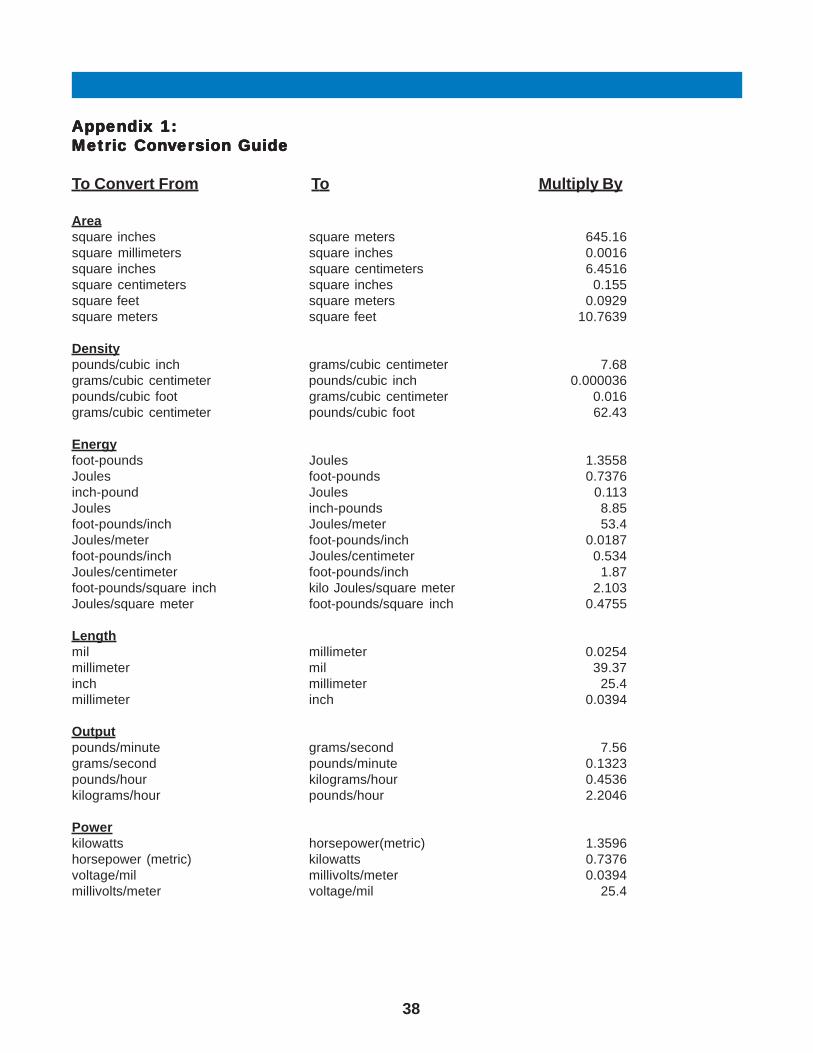
38
AAAAAppendix 1:ppendix 1:ppendix 1:ppendix 1:ppendix 1:Metric ConMetric ConMetric ConMetric ConMetric Convvvvvererererersion Guidesion Guidesion Guidesion Guidesion Guide
To Convert From To Multiply By
Areasquare inches square meters 645.16square millimeters square inches 0.0016square inches square centimeters 6.4516square centimeters square inches 0.155square feet square meters 0.0929square meters square feet 10.7639
Densitypounds/cubic inch grams/cubic centimeter 7.68grams/cubic centimeter pounds/cubic inch 0.000036pounds/cubic foot grams/cubic centimeter 0.016grams/cubic centimeter pounds/cubic foot 62.43
Energyfoot-pounds Joules 1.3558Joules foot-pounds 0.7376inch-pound Joules 0.113Joules inch-pounds 8.85foot-pounds/inch Joules/meter 53.4Joules/meter foot-pounds/inch 0.0187foot-pounds/inch Joules/centimeter 0.534Joules/centimeter foot-pounds/inch 1.87foot-pounds/square inch kilo Joules/square meter 2.103Joules/square meter foot-pounds/square inch 0.4755
Lengthmil millimeter 0.0254millimeter mil 39.37inch millimeter 25.4millimeter inch 0.0394
Outputpounds/minute grams/second 7.56grams/second pounds/minute 0.1323pounds/hour kilograms/hour 0.4536kilograms/hour pounds/hour 2.2046
Powerkilowatts horsepower(metric) 1.3596horsepower (metric) kilowatts 0.7376voltage/mil millivolts/meter 0.0394millivolts/meter voltage/mil 25.4

39
To Convert From To Multiply By
Pressurepounds/square inch (psi) kilopascals (kPa) 6.8948kilopascals (kPa) pounds/square inch (psi) 0.145pounds/square inch (psi) bar 0.0689bar pounds/square inch (psi) 14.51
Temperature°F °C (°F-32)/1.8)°C °F 1.8°C+32
Thermal ConductivityBtu-in/hr, sq. ft.,°F W/(m-°K) 0.1442W / (m-°K) Btu-in/hr,sq ft, °F 6.933
Thermal Expansioninches/inch-°F meters/meter,°C I . 8meters/meter- °C inches/inch, °F 0.556
Viscositypoise Pa-sec. 0.1Pa-sec poise 10
Volumecubic inch cubic centimeter 16.3871cubic centimeter cubic inch 0.061cubic foot cubic meter 0.0.83cubic yard cubic meter 0.765
Weightounce gram 28.3495kilogram ounce 0.03527pound kilogram 0.4536kilogram pound 2.2046ton (US) ton (metric) 0.972ton (metric) ton (US) 1.1023
Coating Weightgrams/meter² pounds/3,000 ft² 0.614
AAAAAppendix 1:ppendix 1:ppendix 1:ppendix 1:ppendix 1: (Contin (Contin (Contin (Contin (Continued)ued)ued)ued)ued)Metric ConMetric ConMetric ConMetric ConMetric Convvvvvererererersion Guidesion Guidesion Guidesion Guidesion Guide

40
AAAAAppendix 2:ppendix 2:ppendix 2:ppendix 2:ppendix 2:
AbAbAbAbAbbrbrbrbrbreeeeeviaviaviaviaviationstionstionstionstionsASTM American Society for Testing and MaterialsBOPP Biaxially oriented polypropyene filmBtu British thermal unitBUR Blowup ratiodeg Degree (angle)E Modulus of elasticityEEA Ethylene-ethyl acrylate copolymerElong ElongationEMA Ethylene methyl acrylic copolymerESCR Environmental stress cracking resistanceEVA Ethylene vinyl acetate copolymerEVOH Ethylene vinyl alcohol copolymerFDA Food and Drug Administrationflex Flexuralg GramHDPE High density polyethyleneHMW High molecular weightIBC Internal bubble coolingimp ImpactIR InfraredJ JouleK Kelvinkpsi 1,000 pounds per square inchL/D Length to diameter ratio of screwlbf Pound-forceLDPE Low density polyethyleneLLDPE Linear low density polyethyleneMD Machine directionMDPE Medium density polyethyleneMFR Melt flow rateMl Melt indexMIL Military, as in Military Standard (MIL STD)mod Modulusmol% Mole percentMW Molecular weightN NewtonPCR Post-consumer resinPE PolyethylenePP Polypropylenepphr Parts per hundred resin, parts per hourppm Parts per millionpsi Pounds per square inchRH Relative humidityrpm Revolutions per minutesp gr Specific gravitySPE Society of Plastics EngineersSPI The Society of the Plastics IndustryTD Transdirectionalten. TensileTg Glass transition temperature (crystalline polymers)Tm Melt temperature (amorphous polymers)ult UltimateUV UltravioletVA Vinyl acetateWVTR Water vapor transmission rateyld Yield
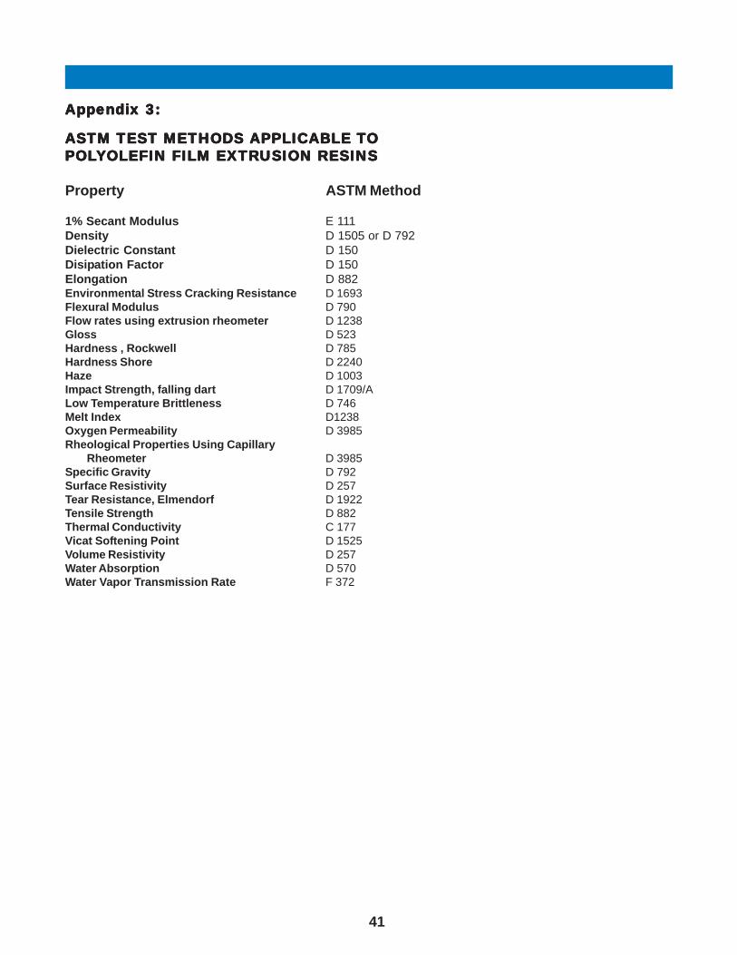
41
AAAAAppendix 3:ppendix 3:ppendix 3:ppendix 3:ppendix 3:
ASTM ASTM ASTM ASTM ASTM TEST METHODS TEST METHODS TEST METHODS TEST METHODS TEST METHODS APPLICABLE APPLICABLE APPLICABLE APPLICABLE APPLICABLE TTTTTOOOOOPOLPOLPOLPOLPOLYYYYYOLEFIN FILM EXTROLEFIN FILM EXTROLEFIN FILM EXTROLEFIN FILM EXTROLEFIN FILM EXTRUSION RESINSUSION RESINSUSION RESINSUSION RESINSUSION RESINS
Property ASTM Method
1% Secant Modulus E 111Density D 1505 or D 792Dielectric Constant D 150Disipation Factor D 150Elongation D 882Environmental Stress Cracking Resistance D 1693Flexural Modulus D 790Flow rates using extrusion rheometer D 1238Gloss D 523Hardness , Rockwell D 785Hardness Shore D 2240Haze D 1003Impact Strength, falling dart D 1709/ALow Temperature Brittleness D 746Melt Index D1238Oxygen Permeability D 3985Rheological Properties Using Capillary
Rheometer D 3985Specific Gravity D 792Surface Resistivity D 257Tear Resistance, Elmendorf D 1922Tensile Strength D 882Thermal Conductivity C 177Vicat Softening Point D 1525Volume Resistivity D 257Water Absorption D 570Water Vapor Transmission Rate F 372

42
AAAAAppendix 4:ppendix 4:ppendix 4:ppendix 4:ppendix 4:
TTTTTrrrrrade Names fade Names fade Names fade Names fade Names for Pror Pror Pror Pror Products ofoducts ofoducts ofoducts ofoducts of Equistar Chemicals Equistar Chemicals Equistar Chemicals Equistar Chemicals Equistar ChemicalsAlathon® HDPE Polyethylene ResinsAquathene® Ethylene vinylsilane compounds for wire and cableFlexathene® Thermoplastic Polyolefin ResinsIntegrate™ Functionalized PolyolefinsMicrothene® Powdered polyethylene resinsPetrothene® Polyethylene and polypropylene resinsPlexar® Tie-layer resinsUltrathene® Ethylene vinly acetate (EVA) copolymer resins

Lyondell Chemical Company1221 McKinney Street, Suite 1600P.O. Box 2483Houston, TX 77252-2583
Cincinnati Technology Center11530 Northlake DriveCincinnati, OH 45249(513) 530-4000
6047/1004
The information in this document is, to ourknowledge, true and accurate. However, sincethe particular uses and the actual conditions ofuse of our products are beyond our control,establishing satisfactory performance of ourproducts for the intended application is thecustomer’s sole responsibility. All uses ofEquistar products and anywritten or oralinformation, suggestions or technical advicefrom Equistar are without warranty, express orimplied, and are not an inducement to use anyprocess or product in conflict with any patent.
Equistar materials are not designed ormanufactured for use in implantation in thehuman body or in contact with internal bodyfluids or tissues. Equistar makes norepresentation, promise, express warranty orimplied warranty concerning the suitability ofthese materials for use in implantation in thehuman body or in contact with internal bodytissues or fluids.
More detailed safety and disposal information onour products is contained in the Material SafetyData Sheet (MSDS). All users of our productsare urged to retain and use the MSDS. AnMSDS is automatically distributed uponpurchase/order execution. You may request anadvance or replacement copy by calling ourMSDS Hotline at (800) 700-0946).
® Acrythene, Alathon, Flexathene, Integrate,Microthene, Petrothene, Petrothene Select,Plexar and Ultrathene are trademarks ofEquistar Chemicals, LP.