Filipe Alexandre Andrade Salgado - … · 4 CaseStudy: 8051onCortex-M3 57 4 ... CISC...
187
Filipe Alexandre Andrade Salgado setembro de 2017 UMinho | 2017 FAT-DBT Engine (Framework for Application-Tailorcd, Co-designcd DynamicBinary Translation Enginc) Universidade do Minho Escola de Engenharia Filipe Alexandre Andrade Salgado FAT-DBT Engine (Framework for Application-Tailorcd, Co-designcd Dynamic Binary Translation Enginc)
Transcript of Filipe Alexandre Andrade Salgado - … · 4 CaseStudy: 8051onCortex-M3 57 4 ... CISC...
Filip
e Al
exan
dre
Andr
ade
Salga
do
setembro de 2017UMin
ho |
201
7FA
T-DB
T En
gine
(Fra
mew
ork
for
Appl
icat
ion-
Tailo
rcd,
Co-
desi
gncd
Dyn
amic
Bina
ry T
rans
latio
n En
ginc
)
Universidade do MinhoEscola de Engenharia
Filipe Alexandre Andrade Salgado
FAT-DBT Engine(Framework for Application-Tailorcd,Co-designcd DynamicBinary Translation Enginc)


setembro de 2017
Tese de DoutoramentoPrograma Doutoral emEngenharia Eletrónica e de Computadores (PDEEC)
Trabalho efetuado sob a orientação doProfessor Doutor Adriano José da Conceição TavaresProfessor Doutor José Araújo Mendes
Filipe Alexandre Andrade Salgado
FAT-DBT Engine(Framework for Application-Tailorcd,Co-designcd DynamicBinary Translation Enginc)
Universidade do MinhoEscola de Engenharia

DECLARAÇÃO
Nome: Filipe Alexandre Andrade Salgado
Correio electrónico: filipe [email protected]
Tel./Tlm.: 934984144
Número do Bilhete de Identidade: 13206863
Título da dissertação: FAT-DBT Engine (Framework for Application-Tailorcd, Co-designcd Dynamic Binary Translation Enginc)
Ano de conclusão: 2017
Orientadores:
Doutor Adriano José da Conceição Tavares
Doutor José Araújo Mendes
Designação do Doutoramento: Programa Doutoral em Engenharia Eletrónica e de Computadores (PDEEC)
Área de Especialização: Informática Industrial e Sistemas Embebidos
Escola: Escola de Engenharia
Departamento: Departamento de Electrónica Industrial
É AUTORIZADA A REPRODUÇÃO INTEGRAL DESTA DISSERTAÇÃO APENAS PARA
EFEITOS DE INVESTIGAÇÃO, MEDIANTE DECLARAÇÃO ESCRITA DO INTERESSA DO, QUE A
TAL SE COMPROMETE.


Acknowledgments
Thank you very much to everyone who contributed to the completion of this thesis.I must mention my advisor Dr. Adriano Tavares for the valuable guidance throughall this years, also Dr. Jorge Cabral and Professor João Monteiro for their supportand Dr. Mongkol Ekpanyapong for his advise during my stay abroad. More thanowing great respect to all of you, allow me to consider you great friends of minealso.
I must also address a special word of gratitude to my friends and great companionsof journey Tiago Gomes and Tiago Gomes, Sadro Pinto, and each and everyonewho contributed to alleviate the burden of this quest.
My last and deepest gratitude is addressed to my fiancée Adriana, for her sincerelove and support, confidence in my capabilities and cheering in the darkest mo-ments; my father, my mother, my sister and close family for their affection andtrust in me and in my life path; and to the cosmos.
This thesis was supported by a PhD scholarship from Fundação para a Ciência eTecnologia, SFRH/BD/81681/2011.
Filipe Salgado
Guimarães, September, 2017.
iii

"Quem quer passar além do BojadorTem que passar além da dor."
Fernando Pessoa


AbstractDynamic binary translation (DBT) has emerged as an execution engine that mon-itors, modifies and possibly optimizes running applications for specific purposes.DBT is deployed as an execution layer between the application binary and the op-erating system or host-machine, which creates opportunities for collecting runtimeinformation. Initially, DBT supported binary-level compatibility, but based on thecollected runtime information, it also became popular for code instrumentation,ISA-virtualization and dynamic-optimization purposes.
Building a DBT system brings many challenges, as it involves complex componentsintegration and requires deep architectural level knowledge. Moreover, DBT incursin significant overheads, mainly due to code decoding and translation, as well asexecution along with general functionalities emulation. While initially conceivedbearing in mind high-end architectures for performance demanding applications,such challenges become even more evident when directing DBT to embedded sys-tems. The latter makes an effective deployment very challenging due to its com-plexity, tight constraints on memory, and limited performance and power. Legacysupport and binary compatibility is a topic of relevant interest in such systems,due to their broad dissemination among industrial environments and wide uti-lization in sensing and monitoring processes, from yearly times, with considerablemaintenance and replacement costs.
To address such issues, this thesis intents to contribute with a solution that lever-ages an optimized and accelerated dynamic binary translator targeting resource-constrained embedded systems while supporting legacy systems.
The developed work allows to: (1) evaluate the potential of DBT for legacy sup-port purposes on the resource-constrained embedded systems; (2) achieve a config-urable DBT architecture specialized for resource-constrained embedded systems;(3) address DBT translation, execution and emulation overheads through the com-bination of software and hardware; and (4) promote DBT utilization as a legacysupport tool for the industry as a end-product.
vii


ResumoA tradução binária dinâmica (TBD) emergiu como um motor de execução quepermite a modificação e possível optimização de código executável para um deter-minado propósito. A TBD é integrada nos sistemas como uma camada de execuçãoentre o código binário executável e o sistema operativo ou a máquina hospedeiraalvo, o que origina oportunidades de recolha de informação de execução.
A criação de um sistema de TBD traz consigo diversos desafios, uma vez que en-volve a integração de componentes complexos e conhecimentos aprofundados dasarquitecturas de processadores envolvidas. Ademais, a utilização de TBD gera di-versos custos computacionais indirectos, maioritariamente devido à descodificaçãoe tradução de código, bem como emulação de funcionalidades em geral. Con-siderando que a TBD foi inicialmente pensada para sistemas de gama alta, osdesafios mencionados tornam-se ainda mais evidentes quando a mesma é aplicadaem sistemas embebidos. Nesta área os limitados recursos de memória e os exigentesrequisitos de desempenho e consumo energético,tornam uma implementação efi-ciente de TBD muito difícil de obter. Compatibilidade binária e suporte a códigode legado são tópicos de interesse em sistemas embebidos, justificado pela ampladisseminação dos mesmos no meio industrial para tarefas de sensorização e mon-itorização ao longo dos tempos, reforçado pelos custos de manutenção adjacentesà sua utilização.
Para endereçar os desafios descritos, nesta tese propõe-se uma solução para poten-cializar a tradução binária dinâmica, optimizada e com aceleração, para suporte acódigo de legado em sistemas embebidos de baixa gama.
O trabalho permitiu (1) avaliar o potencial da TBD quando aplicada ao suportea código de legado em sistemas embebidos de baixa gama; (2) a obtenção deuma arquitectura de TBD configurável e especializada para este tipo de sistemas;(3) reduzir os custos computacionais associados à tradução, execução e emulação,através do uso combinado de software e hardware; (4) e promover a utilização naindustria de TBD como uma ferramenta de suporte a código de legado.
ix


Contents
Acknowledgments iii
Abstract vii
Resumo ix
Acronyms xxi
1 Introduction 11.1 Scope . . . . . . . . . . . . . . . . . . . . . . . . . . . . . . . . . . 91.2 Research Questions and Methodology . . . . . . . . . . . . . . . . . 151.3 State of the Art . . . . . . . . . . . . . . . . . . . . . . . . . . . . . 161.4 Thesis Structure . . . . . . . . . . . . . . . . . . . . . . . . . . . . . 201.5 Conclusions . . . . . . . . . . . . . . . . . . . . . . . . . . . . . . . 21
2 Research Tools and Materials 232.1 Source and Target Architectures . . . . . . . . . . . . . . . . . . . . 23
2.1.1 Source Candidates . . . . . . . . . . . . . . . . . . . . . . . 252.1.2 Target Candidates . . . . . . . . . . . . . . . . . . . . . . . 26
2.2 MCS-51 Architecture . . . . . . . . . . . . . . . . . . . . . . . . . . 272.3 ARMv7-M Architecture . . . . . . . . . . . . . . . . . . . . . . . . 29
2.3.1 ARM CoreSight Architecture . . . . . . . . . . . . . . . . . 322.4 Development Platform . . . . . . . . . . . . . . . . . . . . . . . . . 342.5 Benchmarking Tools . . . . . . . . . . . . . . . . . . . . . . . . . . 36
2.5.1 BEEBS . . . . . . . . . . . . . . . . . . . . . . . . . . . . . 37
3 Designing a Dynamic Binary Translator 393.1 Introduction . . . . . . . . . . . . . . . . . . . . . . . . . . . . . . . 393.2 Generic DBT Architecture . . . . . . . . . . . . . . . . . . . . . . . 413.3 Requirements and Design Decisions . . . . . . . . . . . . . . . . . . 44
xi

3.4 Deployment Insight . . . . . . . . . . . . . . . . . . . . . . . . . . . 453.4.1 Retargetability Support . . . . . . . . . . . . . . . . . . . . 463.4.2 DBT Engine . . . . . . . . . . . . . . . . . . . . . . . . . . . 503.4.3 Translation to Execution Switch . . . . . . . . . . . . . . . . 513.4.4 Memory Support Structures . . . . . . . . . . . . . . . . . . 523.4.5 Helper Function Calls . . . . . . . . . . . . . . . . . . . . . 54
3.5 Conclusions . . . . . . . . . . . . . . . . . . . . . . . . . . . . . . . 55
4 Case Study: 8051 on Cortex-M3 574.1 Pairing the MCS-51 and the ARMv7-M Architectures . . . . . . . . 57
4.1.1 Source Specific Porting . . . . . . . . . . . . . . . . . . . . . 594.1.2 Target Specific Porting . . . . . . . . . . . . . . . . . . . . . 654.1.3 Condition Codes . . . . . . . . . . . . . . . . . . . . . . . . 70
4.2 Tests and Results Discussion . . . . . . . . . . . . . . . . . . . . . . 724.3 Conclusions . . . . . . . . . . . . . . . . . . . . . . . . . . . . . . . 79
5 Handling the Condition Codes 835.1 Introduction . . . . . . . . . . . . . . . . . . . . . . . . . . . . . . . 835.2 Condition Codes Evaluation . . . . . . . . . . . . . . . . . . . . . . 86
5.2.1 Standard CC Evaluation . . . . . . . . . . . . . . . . . . . . 865.2.2 Traditional Lazy Evaluation . . . . . . . . . . . . . . . . . . 875.2.3 CC Lazy Evaluation Integrated with Debug Features . . . . 88
5.3 System Evaluation . . . . . . . . . . . . . . . . . . . . . . . . . . . 905.4 Conclusion . . . . . . . . . . . . . . . . . . . . . . . . . . . . . . . . 92
6 Non-intrusive Hardware-Assisted Acceleration 936.1 Introduction . . . . . . . . . . . . . . . . . . . . . . . . . . . . . . . 946.2 Tcache Acceleration Assisted by Hardware . . . . . . . . . . . . . . 99
6.2.1 Proposed Solution . . . . . . . . . . . . . . . . . . . . . . . 996.2.2 Interface and Software API . . . . . . . . . . . . . . . . . . 101
6.3 Non-Intrusive DBT Acceleration Module . . . . . . . . . . . . . . . 1046.3.1 Architecture . . . . . . . . . . . . . . . . . . . . . . . . . . . 1046.3.2 Interface and Software API . . . . . . . . . . . . . . . . . . 106
6.4 CC Handling . . . . . . . . . . . . . . . . . . . . . . . . . . . . . . 1096.5 Peripheral Remapping . . . . . . . . . . . . . . . . . . . . . . . . . 1116.6 Interrupt Support . . . . . . . . . . . . . . . . . . . . . . . . . . . . 1146.7 Conclusions . . . . . . . . . . . . . . . . . . . . . . . . . . . . . . . 117

7 Automation Enablement through DSL 1217.1 Introduction . . . . . . . . . . . . . . . . . . . . . . . . . . . . . . . 1217.2 DSL for DBT . . . . . . . . . . . . . . . . . . . . . . . . . . . . . . 1237.3 FAT-DBT - EL and Framework Overview . . . . . . . . . . . . . . 1247.4 Modeling the DBT Engine . . . . . . . . . . . . . . . . . . . . . . . 1277.5 Implementation . . . . . . . . . . . . . . . . . . . . . . . . . . . . . 1287.6 Evaluation . . . . . . . . . . . . . . . . . . . . . . . . . . . . . . . . 1307.7 Conclusion . . . . . . . . . . . . . . . . . . . . . . . . . . . . . . . . 134
8 Conclusions and Future Work 1358.1 Conclusions . . . . . . . . . . . . . . . . . . . . . . . . . . . . . . . 1358.2 Limitations . . . . . . . . . . . . . . . . . . . . . . . . . . . . . . . 1388.3 Future Work . . . . . . . . . . . . . . . . . . . . . . . . . . . . . . . 1398.4 List of Publications . . . . . . . . . . . . . . . . . . . . . . . . . . . 142
Bibliography 143
xiii

xiv

List of Figures
1.1 Binary translation general concept. . . . . . . . . . . . . . . . . . . 41.2 Solution space. . . . . . . . . . . . . . . . . . . . . . . . . . . . . . 101.3 State of the art placement in the solution space. . . . . . . . . . . . 20
2.1 8051 data memory mapping. . . . . . . . . . . . . . . . . . . . . . . 292.2 MCS-51 Program Status Word (PSW). . . . . . . . . . . . . . . . . 292.3 ARMv7-M address space. . . . . . . . . . . . . . . . . . . . . . . . 302.4 ARMv7-M registers. . . . . . . . . . . . . . . . . . . . . . . . . . . 312.5 ARMv7-M APSR bits. . . . . . . . . . . . . . . . . . . . . . . . . . 322.6 Cortex-M3 CoreSight debug architecture. . . . . . . . . . . . . . . . 332.7 SmartFusion2 system-on-chip (SoC) FPGA simplified block diagram. 352.8 SmartFusion2 SoC field-programmable gate array (FPGA) Advanced
Development Kit [1]. . . . . . . . . . . . . . . . . . . . . . . . . . . 36
3.1 DBT engine architectural model. . . . . . . . . . . . . . . . . . . . 413.2 DBT engine flowchart. . . . . . . . . . . . . . . . . . . . . . . . . . 50
4.1 MCS-51 LJMP addr16 encoding and operation. . . . . . . . . . . . 624.2 MCS-51 RET encoding and operation. . . . . . . . . . . . . . . . . 624.3 MCS-51 ADD A, #data encoding and operation. . . . . . . . . . . 624.4 MCS-51 DA encoding and operation. . . . . . . . . . . . . . . . . . 654.5 Thumb-2 LDRB (immediate) - Load Register Byte (immediate) en-
coding. . . . . . . . . . . . . . . . . . . . . . . . . . . . . . . . . . . 684.6 Thumb-2 MOV (immediate) - Move (immediate) encoding. . . . . . 704.7 Thumb-2 ADD (register) encoding. . . . . . . . . . . . . . . . . . . 704.8 Thumb-2 STRB (immediate) - Store Register Byte (immediate) en-
coding. . . . . . . . . . . . . . . . . . . . . . . . . . . . . . . . . . . 704.9 Target/source global execution ratio, for different Tcache sizes. . . . 744.10 Target/source global execution ratio, for linked list and hash table
Tcache managements for different Tcache sizes. . . . . . . . . . . . . 76
xv

4.11 Global execution characterization in percentage, for different Tcachesizes. . . . . . . . . . . . . . . . . . . . . . . . . . . . . . . . . . . . 77
4.12 Execution characterization in percentage, for different Tcache sizes. 784.13 Total CC handling characterization in percentage, for different Tcache
sizes. . . . . . . . . . . . . . . . . . . . . . . . . . . . . . . . . . . . 79
5.1 Target/source global execution ratio, for the standard, lazy evalua-tion and debug monitor CC evaluation, using the linked list Tcachemanagement, for different Tcache sizes. . . . . . . . . . . . . . . . . 90
6.1 Tcache hardware manager diagram. . . . . . . . . . . . . . . . . . . 1006.2 Tcache hardware manager peripheral mapping. . . . . . . . . . . . . 1016.3 Target/source global execution ratio, for linked list, hash table and
hardware based Tcache managements for different Tcache sizes. . . 1036.4 Non-intrusive hybrid acceleration architecture. . . . . . . . . . . . . 1056.5 Tcache hardware manager peripheral mapping. . . . . . . . . . . . . 1076.6 Target/source global execution ratio, for the standard, lazy eval-
uation, debug monitor and sniffer based CC evaluation, using thehardware managed Tcache, for different Tcache sizes. . . . . . . . . 110
6.7 Peripheral emulation sequence diagram. . . . . . . . . . . . . . . . . 1136.8 Received message from the MCS-51 remapped UART transmission
by polling. . . . . . . . . . . . . . . . . . . . . . . . . . . . . . . . . 1136.9 Interrupt emulation sequence diagram. . . . . . . . . . . . . . . . . 1166.10 Received message from the MCS-51 remapped UART transmission
by interrupt. . . . . . . . . . . . . . . . . . . . . . . . . . . . . . . . 117
7.1 Elaboration Language framework workflow. . . . . . . . . . . . . . . 1247.2 Reference architecture. . . . . . . . . . . . . . . . . . . . . . . . . . 1277.3 XML Component Editor interface for the TranslationCache compo-
nent. . . . . . . . . . . . . . . . . . . . . . . . . . . . . . . . . . . . 1327.4 XML Component Editor interface for the Generator component. . . 1337.5 The compiled DBT source files executing on the evaluation board,
translating a program written for MCS-51 architecture. . . . . . . . 133
xvi
List of Tables
1.1 Gap analysis between existing DBT engines. . . . . . . . . . . . . . 19
2.1 BEEBS benchmarks specs, and compile and simulation results. . . . 38
4.1 MCS-51 CC flags affectation. . . . . . . . . . . . . . . . . . . . . . 714.2 BEEBS benchmarks results in clock cycles for different Tcache sizes. 73
6.1 Tcache hardware manager FPGA resource utilization. . . . . . . . . 1036.2 Sniffer module FPGA resource utilization. . . . . . . . . . . . . . . 106
7.1 Available EL’s keywords. . . . . . . . . . . . . . . . . . . . . . . . . 126
xvii

xviii
Listings
3.1 IR micro operations declared as pure virtual methods. . . . . . . . . 473.2 Translator class header file. . . . . . . . . . . . . . . . . . . . . . . 483.3 Translation to Execution switch code snippet. . . . . . . . . . . . . 514.1 Decoding method code snippet. . . . . . . . . . . . . . . . . . . . . 614.2 Helper function usage example. . . . . . . . . . . . . . . . . . . . . 644.3 DA emulation helper function. . . . . . . . . . . . . . . . . . . . . . 654.4 Working registers definition code snippet. . . . . . . . . . . . . . . . 674.5 Prologue and epilogue decomposition into micro operations. . . . . 674.6 Gen_ld8 micro operation code generation. . . . . . . . . . . . . . . 684.7 Gen_movi micro operation code generation. . . . . . . . . . . . . . 694.8 Gen_add micro operation code generation. . . . . . . . . . . . . . . 694.9 Gen_st8 micro operation code generation. . . . . . . . . . . . . . . 694.10 Gen_helper micro operation code generation. . . . . . . . . . . . . 704.11 Gen_assemble_CC_param code generation. . . . . . . . . . . . . . 725.1 CC update helper function generation. . . . . . . . . . . . . . . . . 875.2 Lazy evaluation CC handling example code snippet. . . . . . . . . . 875.3 Debug monitor DWT comparator control code snippet. . . . . . . . 896.1 Tcache hardware manager driver. . . . . . . . . . . . . . . . . . . . 1016.2 Linker configuration file (.icf) snippet. . . . . . . . . . . . . . . . . 1076.3 SBUF write action helper function. . . . . . . . . . . . . . . . . . . 1127.1 EL representation of TranslationCache component. . . . . . . . . . 1287.2 EL representation of the i_TCache interface. . . . . . . . . . . . . . 1287.3 EL representation of C++ language. . . . . . . . . . . . . . . . . . 1297.4 Example of annotations. . . . . . . . . . . . . . . . . . . . . . . . . 1307.5 Elaboration file. . . . . . . . . . . . . . . . . . . . . . . . . . . . . . 1307.6 TranslationCache specific XML configuration file. . . . . . . . . . . 1317.7 Specific XML configuration file. . . . . . . . . . . . . . . . . . . . . 132
xix

xx
Acronyms
4LUT 4-input Look-Up Table
AAPCS Procedure Call Standard for the ARM Architecture
ABI application binary interface
AC Auxiliary Carry flag
ACC Accumulator
AES Advanced Encryption Standard
ALU arithmetic logic unit
AMBA Advanced Microcontroller Bus Architecture
APSR Application Status Register
BB Basic Block
BT Binary Translation
BCD binary-coded decimal
BEEBS Bristol Energy Efficiency Benchmark Suite
CAD computer-aided design
CAM content-addressable memory
CBD component-based development
CC Condition Codes
Ccache source code cache
xxi

CISC complex instruction set computer
COTS commercial off-the-shelf
CY Carry flag
DBT dynamic binary translation
DBTor dynamic binary translator
DSL domain-specific language
DSP digital signal processing
DDR double data rate memory
DFF D-type flip-flop
DIMM dual in-line memory module
DPTR Data Pointer
DWT Data Watchpoint and Trace unit
ECC elliptic curve cryptographic
EDA electronic design automation
EL Elaboration Language
EPSR Execution Program Status Register
eNVM embedded Non-Volatile Memory
ETM Embedded Trace Macrocell
FIC Fabric Interface Controller
FPB Flash Patch Breakpoint unit
FPGA field-programmable gate array
GCC GNU Compiler Collection
GP generative programming
GPIO general pupose input/output
xxii
GPL general-purpose language
GPU graphics processing unit
GUI graphic user interface
HDL hardware description language
IA Intel Architecture
IDE integrated development environment
ILP instruction-level parallelism
I2C Inter-Integrated Circuit
I/O input/output
IoT Internet of Things
IP intellectual property
IPSR Interrupt Program Status Register
IR intermediary representation
ISA instruction set architecture
ISR interrupt service routine
ITM Instrumentation Trace Macrocell
LE Lazy Evaluation
LR Link Register
LE logic elements
LSB least significant bit
MDD model driven development
MMU memory management unit
MSB most significant bit
MSS microcontroller subsystem
xxiii
NRE non-recurring engineering
NRBG non-deterministic random bit generator
OO object-oriented
OS operating system
OV Overflow flag
P Parity
PC Program Counter
PSW Program Status Word
RAM random-access memory
RISC reduced instruction set computer
RTOS real-time operating system
SBT static binary translation
SCA Service Component Architecture
SPM Scratchpad Memory
SEU single event upset
SERDES Serializer and Deserializer
SFR Special Function Register
SHA Secure Hash Algorithm
SOA service oriented architecture
SoC system-on-chip
SP Stack Pointer
SPI Serial Peripheral Interface
SRAM static random-access memory
TBB translated Basic Block
xxiv

TCM Tightly Coupled Memory
TPIU Trace Port Interface Unit
Tcache Translation cache
UART universal asynchronous receiver-transmitter
USART universal synchronous asynchronous receiver-transmitter
VLIW very long instruction word
xxv

xxvi

Chapter 1
Introduction
In the present embedded systems’ development trend, hardware is constantlyevolving to meet the performance hungry market requirements. The commonlyused method to increase performance can no longer be applied due to power con-straints, but one approach is gathering consensus: the multi-core approach [2–5].Multiple cores per chip increase the instruction level parallelism and by using spe-cialized cores for specific tasks, rather than general processor cores. Therefore,the efficiency can be greatly improved, resulting in much lower power consump-tion [2,6]. Furthermore, the use of different cores simplifies the partitioning of dif-ferent clock frequencies among the various system’s cores in order to obtain largepower savings and clock skew attenuation [6,7]. However multi-core architectures,tend to increase the price of the processor and, if not managed correctly, may havethe opposite effect on the energy consumption. Thus multi-core approaches mustbe carefully evaluated on pair with the system’s expected workload.
System variability is also hampering embedded systems development, due to theblooming of hardware and software integration possibilities. The ad-hoc integra-tion of components in a system is no longer prudent once possible combinationsarise exponentially. Moreover, functionality reuse and automatic code generationmust be considered as a requirement, otherwise developers risk cost-ineffective pro-duction. To solve system variability concerns, corroborated software developmenttechniques have being increasingly adopted. Techniques such as component-baseddevelopment (CBD), model driven development (MDD), service oriented architec-ture (SOA) and generative programming (GP) are being applied in hardware de-velopment [8–11]. Applying CBD and MDD in full system deployment is justifiedby their efficiency in dealing with system modeling and functionalities description
1
and fusion. A design flow for hardware using MDD was proposed in [8, 9] takingadvantage of system’s meta-model specification. In [8], a high abstraction systemlevel model using MDD model transformations was refined until the model reachesa detail level to automatically generate hardware description language (HDL) code.The model does not allow architecture exploration and performance analysis. In [9]a rapid prototyping tool (LavA) based on interconnected open-source tools wasproposed. LavA successfully adopted software techniques to hardware, raising theabstraction level of hardware design. Similarly in [10], attention is drawn to MDD,using model transformation, concluding that there is a real need for techniques tomodel complex hardware systems.
Beside the mentioned fabrication process and development limitations, softwareand hardware legacy compatibility are also obstacles to advances in novel deploy-ments. Legacy support for architectural compatibility must be assured, otherwisethe novel hardware risks market rejection. Legacy support has multiple costs:
1. Hardware engineers must pay special attention, and spend valuable engineer-ing effort to provide legacy support features to novel products;
2. These features might limit new products’ performance due to backward com-patibility;
3. Legacy support features may incur in significant runtime overhead.
On top of these constraints, embedded systems’ design has tighter specificationsthan general purpose systems’ design, due to smaller memory sizes, limited process-ing power and less resource abundant architectures. However these characteristicsare the ones that mostly account to these system’s reduced price, which is perhapsthe main aspect that leads to their broad adoption in the industry’s sensing andmonitoring and control applications, home automation, small appliances, mobiledevices, technology gadgets, etc. Even in the embedded systems category, there is agreat variety of devices, with different architectures, processing power, power con-sumption and memory resources, among other characteristics. Here, also the lowerresourced systems will have a smaller cost than the well endowed ones. Therefore,embedded systems may also be categorized mainly as low-end and high-end. Theseparation boundary is not well defined, but a low-end or resource-constrainedembedded systems typically have a single core, a clock frequency up to 100 MHz,memory resources up to 128 KB random-access memory (RAM) and 256 KB flashand by last, should cost well bellow the $10 price mark [12]. These type of systems
2
are well disseminated as commercial off-the-shelf (COTS) solutions, thus its us-age is leveraged from immediate commercial availability, ready-to-use developmentplatforms and vast support and tool-chains, resulting in faster time-to-market.
It is precisely the low-end embedded systems that proliferate in the industry sinceearly times, due to their broad dissemination and wide utilization in sensing andmonitoring processes. Many of these systems are still correctly working and underuse at the current days, however, there are risks and costs that arise with suchutilization:
1. These systems have higher maintenance costs due to obsolete componentsutilization;
2. A system failure may results in heavy production loss since there are noreplacement parts;
3. Legacy systems tend to be very energy inefficient;
4. They were not designed with security as a concern.
The re-design of these embedded systems is often costly due to several causes:
5. The source code of the firmware does not exist or was lost, therefore recom-pilation of the code to modern systems is not possible;
6. A modern replacement system involves the design from scratch of the wholesolution, including requirements gathering, non-recurring engineering (NRE)development costs, testing and sometimes certification costs of complex pro-jects.
Hence, the possibility of using the legacy systems binaries into a contemporaryreplacement platform is highly attractive because not only prevents the events 1., 2.and 3., but also may address the challenges of 4. and alleviates the costs of 5. and6. with the added benefit of the low energy consumption associated with modernarchitectures. This motivates the migration of dynamic binary translation (DBT)techniques to embedded systems for legacy support purposes, most specificallytargeting the low-end architectures due to their reduced price, high versatility,broad dissemination and contained energy consumption.
3

Dynamic Binary Translation
Binary Translation (BT) is a technique that was developed for architectural com-patibility, i.e., to run machine binary code on architectures different from the oneit was compiled for (Figure 1.1). This technique also eases the bridging of legacysystems to cheaper and up-to-date platforms [13], providing binary compatibilitywith minimal NRE.
There are several ways to run binary code in a different machine for which itwas produced. The most common ones are using an interpreter (emulator) ora BT [14, 15]. While the former re-creates a source machine architecture modelin software and interprets instructions, the latter translates the binary files andcreates a new machine code to be directly executed in the new target. BT isfor a long time widely accepted as a better solution than pure interpretation dueto performance reasons, from between 5× up to 10× faster [16, 17], and codeoptimization opportunities created during translation process [17–19].
Dynamic over Static BT
There are two approaches to BT, namely static or dynamic. HP labs pioneered thestatic binary translation (SBT), by porting emulation techniques and combining amachine emulator and a code translator [20] . The translators became quite com-mon in the ’90s, when hardware manufacturers provided translators to encompassthe migration from their complex instruction set computer (CISC) instruction setarchitecture (ISA) to reduced instruction set computer (RISC) ISA [20–25]. Staticbinary translators follow the structure of a compiler, having a front-end or a de-
Source Binary Target BinaryBinary
Translation
Figure 1.1: Binary translation general concept.
4
code stage, an analysis and optimization stage and a code generation or back-endstage. SBT works well for bare metal programs or user space programs in systemswith an operating system (OS). These kinds of binaries usually have well sepa-rated code and data memory spaces, and do not use programming techniques suchas self-modifying or dynamic code generation, which makes them very suitablefor SBT [15]. In addition to self-modifying or dynamic code generation, SBT cannot deal efficiently with indirect branches and indexed memory accesses becausethese behaviors rely on computations performed during run time, which are notknown statically. These situations require a fallback mechanism, which emulatesthe runtime environment and interprets untranslated code. When compared toSBT, DBT can solve many of the SBT problems and drawbacks: (1) code discov-ery issues, hard to handle in SBT [26, 27], do not exist in DBT since executablecode is identified during runtime program flow; (2) self modifying code can be han-dled during runtime, by invalidating cached code and generating target machinecode again [14, 15]; (3) indirect jumps and indexed address modes are calculatedand translated during runtime [15]; (4) DBT is exempted of the runtime environ-ment development cost [14]; (5) DBT easily deals with non-user space applications,which means that full systems (OS plus user space binaries) can be translated toanother target architecture [28] by integrating virtualization support in the ISAtranslation layer, opening a new path to system virtualization.
DBT technology has been used to offer several other services than binary code com-patibility, such as, co-design innovative micro-architectures, code security, powermanagement, software caching, program analysis and instrumentation, ISA virtu-alization support, among others. Conceptually, its core consists of a runtime engineand a translator which fetches guest application code, decodes and transforms itaccording to the provided service (e.g., cross ISA compatibility, virtualization, op-timization), while caching the translated code in a translation cache, from whereit executes directly on the target machine. Therefore, DBT technology incurs insignificant overhead which degrades performance due to decoding and translation,optimization, emulation and other potential runtime overheads. Furthermore, theimplementation effort is non-trivial as porting a DBT layer, which is typically ar-chitecture and service-oriented, to a new system, requires considerable engineeringeffort and may incur in unacceptable performance penalties.
5
DBT for Virtualization
Examples of DBT for virtualization purposes are presented in [29–35]. In [32] it ispresented a Linux-based DBT virtualization layer which translates memory pagesdemanded by an application through the use of a co-processor. In [29], DBT isused by VMWare to translate non-virtualizable instructions. In DBTIM [30, 36]the authors provided alternative solutions to paravirtualization in architecturesthat were not meant to be virtualized, using reconfigurable hardware (FPGA) toperform the translations process and replace non-virtualizable instructions. Mod-ern days hypervisors [34,35], still utilize DBT for full-system and application-levelvirtualization on high-end embedded ARM platforms.
DBT for Binary Compatibility
Different reasons, from different interested parties, to invest in legacy support andgood binaries migration solutions are exposed in [14]. They are either organizationsthat want to maximize investments in specially developed software, to take advan-tage of their full capabilities; or hardware designers, who develop new architecturesand want programs migration to run with full performance; or even software de-velopers, who want to guarantee correct functionality of programs for a variety ofplatforms with reduced testing time. FX!32 [16], DAISY [37, 38], Crusoe [39–41],BOA [42–44] and Harmonia [45] are all examples of binary compatibility investi-gation, however not all the discoveries made so far have been made public, due tocommercial interests from the involved parties [14]. The initial trend was to sup-port a competitor’s ISA on a hardware’s developers own architectures [16,37–44] formarket acceptance reasons [16,39] and to benefit from the advantages of very longinstruction word (VLIW) architectures such as design simplicity, high instructionissue rate and high instruction-level parallelism (ILP) [37,39,42]. DAISY [37,38],is one of the pioneer works in DBT for VLIW target architectures. The workaddresses several challenges in DBT, such as, page and address mapping, crossISA Condition Codes (CC) emulation, translation cache management, exceptionscheduling, self-modifying code and aggressive reordering of memory references.Transmeta attempted the same targeting low-cost, high-performance proprietaryVLIW microprocessors with Crusoe [39]. More recently, Harmonia [45] resourcedto DBT to provide compatibility of embedded market associated architectures withIntel Architecture (IA), motivated by the today’s ubiquitous presence of ARM plat-
6

forms. Two challenges were identified: the reduced number of registers in the IAarchitecture and the condition codes handling divergence in both architectures.
DBT for Code Optimization
DBT is also used to accelerate system simulation as shown in [46], where the au-thors demonstrate the use of homogeneous multi-processor system to perform inparallel the translation, optimization and execution of several hot traces. Exam-ples of DBT application in code instrumentation and dynamic optimization arepresented in [47–54]. In DBT, dynamic optimization is tightly related with codeinstrumentation because the optimization actions often result from informationgathered during code runtime instrumentation. Thus the heavy optimization al-gorithms are applied only where hot code traces are detected. Strata [47, 48] andHDTrans [51, 52] are two popular DBT frameworks for this purpose, which maybe extended for specific services (e.g., ISA simulation, instrumentation, OS emu-lation, optimization). The versatility of the STRATA was explored in plenty ofworks based on built around Strata project [55–61]. In fastBT [53,54], Payer andGross propose optimizations to reduce the DBT runtime overheads observed inDynamoRIO [49], HDTrans [51] and PIN [62]. FastBT achieves a low overhead of0% to 10% based on a fast mapping lookup of the trace cache and configurablein-line optimization mechanisms. These DBT systems however do not performcross-ISA translation, since their use is more like a performance monitoring anddevelopment tool, which discourages cross-ISA compatibility application purposes.
DBT to Reduce Energy Consumption
In [63], the authors show how runtime-profiling can be used to perform efficientfrequency and voltage scaling, successfully decreasing the power consumption upto 70%. Other power management techniques are proposed in [64], where runtimeoptimization is used to perform register re-allocation, thus decrease cache accessesand so, reducing the energy consumption. In [65], Schranzhofer et al. proposeda method to minimize the average power consumption by intelligently map tasksto key processing units. The presented method adapts to the current executionpattern. Hong et al. in [66] directly relate the energy consumption with the per-formance and number of instructions executed. In DBT systems, if the translatedcode is far more extensive that the original, it means that not only performance,
7
but also energy consumption will suffer a negative impact. Focusing on mobileapplications, the authors transferred the heavy translation/optimization workloadto a fixed and power unconstrained server, which upon request, receives the IRof hot traces of code, performs aggressive optimizations and sends the result backto the thin client, which has a light translator/emulator running. A remote thinclient was also used in [67, 68] to reduce the DBT negative effects on memory ofresource-constrained systems.
Overheads Mitigation Methods
The main drawback of traditional DBT techniques [48, 69] is the performanceoverhead caused by translation and emulation [70]. This is primarily due to basicemulation algorithms, such as identified in [69], and the difficulty in identifyingproper optimization opportunities. Furthermore, optimizations during runtime area heavy burden, constrained by the amount of time that the system can spend insuch process without performance impact [71]. In [72, 73], the authors faced thehigh overhead of DBT by combining a dynamic binary translator with a previousstatic analysis stage of the code to be translated. With the profile informationcollected statically, some optimization algorithms are run before load time. Thisapproach eliminates the profiling and heavy optimization overheads, resulting ina runtime reduction of more than 34% with a memory increase cost of just 2%.
Dedicated hardware and parallel execution are other approaches to DBT over-head mitigation. Dedicated hardware provides additional processing capabilities todeal with DBT specific tasks without using the existent system processing power.CoDBT [74] attempts to mitigate the performance overhead by migrating DBTfunctionalities to hardware, without making changes to the target processor, suc-cessfully implementing parallelism. GODSON [75] translates x86 binaries to itstarget MIPS architecture through dedicated hardware. The Code Morphing tech-nology implemented in Crusoe [40] translates x86 through a hardware/softwaremix. Alternative DBT uses, such as Warp processing [76], have been used toincrease the optimized code performance, but suffer from significant overheadscaused by FPGA reconfiguration. Task parallelization is another efficient way toreduce overhead and increase performance. This is a buzz area in research sinceone of the modern era uses of DBT is the parallelization of code to increase ILP.Sokolov et al. [77] attempted a software-only solution by performing optimiza-tion in parallel with execution, on a different software thread, running on the
8
same or other core. MTCrossbit [78] and MT-Btrimer [79] use multi-thread exe-cution to address context switching overhead mitigation by mapping translationand executions tasks into different software threads [78]. MT-Btrimer also per-forms speculative code translation on a master-slave DBT architecture, achievingon average 30% performance improvement at heavy Translation cache (Tcache)burdening cost. In [78], a solution that targets multi-core processors demonstrateshow running each DBT functionality in a different core can contribute to increaseperformance. In [17, 19] the authors try to make full use of multi-core platformsand their performance by parallelizing different DBT tasks like code translation,code optimization, code execution or speculative translation direction estimation.BOA [42–44] also demonstrates the use of DBT to increase performance and pro-cessing speed by using a dedicated processor core for translation.
Legal Considerations
As a final consideration on DBT, the legality of the platform emulation process isalso seen as a barrier to its adoption. The legality issues are split in two aspects:one is related with the emulation of the system and the other is related with thecopy of the software to be emulated [15]. Regarding the creation of an emulator,detailed information must be known about the original architecture and most ofthe times that information is copyrighted. If that information is stolen, or obtainedwithout the consent of the owner, the creator of the emulator may be sewed andthe emulator can never be sold legally. Another way to obtain that information isby reverse engineering, and that technique remains in a gray legal area. Regardingthe software copies, the duplicates of the binaries are illegal unless the owner alsoowns an original copy of that software, which in industry is a mandatory practice,but still a delicate topic. In DBT, in fact no software copies are made, since only atranslation of the original software is stored temporarily at volatile memory, thusno copies persist.
1.1 Scope
This thesis is focused on binary compatibility in embedded systems through DBTtechniques. This motivation comes from the need to provide legacy support forembedded systems binaries at a reduced cost, using COTS products and as a
9

reusable solution, applicable to multiple scenarios. System-level type DBT willbe addressed since most of the low-end industrial legacy systems would likely runbare-metal single task applications, thus the use of an OS can be discarded. Fromthe presented general overview on DBT and embedded systems, certain featuresand characteristics are very favorable to contribute to this thesis goal, such asthe use of COTS embedded devices, cross-ISA translation and hardware acceler-ation. The use of COTS devices contributes to the low price of the final solutionand also favors its deployment due to the availability of ready-to-use developmentplatforms. Cross-ISA translation is crucial to support legacy binaries and, alliedto an intermediary representation (IR) between source and target ISAs, will favorthe portability of the solution to multiple application use cases. Regarding hard-ware acceleration, it is an attractive technique for overhead mitigation and paralleloptimization with little to no impact on the DBT resource allocation, that appliedin embedded systems might solve many performance issues. Reconfigurable hard-ware is also becoming a common feature in today’s COTS embedded SoC, whichis a opportunity that should be explored. The solution must also be integrated ona framework that may provide a higher abstraction level model for configurationand customization, and that enables automatic code generation and solution spaceexploration.
Thus the solution space of this work is configured between (1) a legacy support
LegacySupport
EmbeddedSystems
Portability &Customization
HarddwareAcceleration
SolutionSpace
Figure 1.2: Solution space.
10
at binary level, (2) low-end COTS embedded systems, (3) ease of customization,resourceability and retargetability for different application and (4) acceleration/op-timization through hardware, as illustrated in Figure 1.2.
A deeper analysis on DBT resourceability and retargetability through IR, hardwareassisted DBT and automation enablement solution are presented ahead.
Despite most of the optimizations carry out in DBT system being to increase per-formance, when considering an embedded environment, energy constraints shouldalso be highly considered as an optimization goal. However, this thesis does notdirectly addresses such issues due to scope limitations. Other relevant and inter-esting concerns that are also kept away from the scope are real time requirements,application level DBT and ILP exploration either by multi-thread or multi-coreapproaches.
Resourceable and Retargetable DBT through IR
A DBT engine which performs runtime optimization requires a structure similar toa compiler. It has a front-end or a decode stage, that produces an IR of the sourcebinaries; a middle-end where code analyses and optimizations are performed overthe IR; and a back-end stage, where the target code is generated [80].
For resourceable and/or retargetable translators, i.e., translators that use the sameintermediate structure to translate code from multiple source architectures to mul-tiple target machines, the use of the IR brings additional advantages, since the IRacts like an abstraction layer between the source and target ISAs, decoupling thecode decoding and generation stages [81]. In practical terms, the decoding stageof an IR resorting DBT engine must decompose the source instructions into IRsub instructions, and the code generator must generate target code for each ofthe IR’s sub instructions. This approach separates the source and target specificcomponents of the translator from the DBT kernel, and introduces different sourceor target architectures support without considering the counterpart architecture,since the porting must address the IR only.
DesIRer [81] is a multi-platform binary translator which applied the conversionof the GNU Compiler Collection (GCC) into a retargetable binary translator.The IR and back-end of the compiler is inherited by the developed translator formulti-target support as an economic way for obtaining retargetability in binarytranslation. For an x86 to ARM translation, performance degradation was ob-
11
served due to translation overheads from load and store instructions introducedby the CISC to RISC translations.
Bintrans [82–84] is a machine adaptable binary translator, at application-level,for Linux. The work is a cross-ISA translator developed for the purpose of DBTresearch and supporting translation from source x86 and PowerPC to Alpha andPowerPC target architectures. The authors also achieve resourceability and retar-getability by using and IR for front-end and back-end separation, and identify thedisadvantages of such approach, namely: (1) translation through IR is slower thantranslating directly from source to target code, as also identified in [85]; and (2) itis hard to obtain an IR which can capture every ISA’s architectural details, (e.g.,CC), and the broader the IR the less efficient target code generation is.
Bellard developed QEMU [86], a popular portable machine emulator that usesDBT for optimization of frequently executed code blocks. QEMU supports full-system emulation and user-level emulation for Linux OS. The multiple architecturesupport is implemented through an IR which usesmicro operations to represent thesource instructions into target architecture binary code. The vast disseminationand popularity of QEMU is due to its great portability and architectures support,achieved though the use of the IR. Originally the QEMU IR was ported through"dyngen", using micro operations object file information as input to generate targetmachine code. QEMU is a desktop application, thus uses large translation caches(16 MB) to accommodate the translated code and performs simple optimizationssuch as lazy evaluation of the CC and direct block chaining.
In Hermes [87], the use of an IR is identified as severe source of performancepenalty, preventing effective ISA-specific optimizations. Hermes addresses thisby eliminating the ISA and performing post-optimization on the generated codeand not on the IR, as commonly performed. The authors claim that the tech-nique used, Host-specific Data Dependence Graph, compared to QEMU, is able toachieve performance speed-up up to 3.14× and 5.18× for x86 and ARM guest ISAs,respectively, preserving the portability offered by and IR. However this approachwas deployed on a superscalar processor [75], thus its use in resource-constrainedembedded systems is highly discouraged.
CrossBit [88] is a multi-source multi-target cross-ISA DBT. Like QEMU [86], ituses an intermediate representation, VInst, between source and target instructionsas an abstraction layer in order to ease the multi source and target portability.CrossBit was able to outperform QEMU in several benchmarks due to several
12

optimization efforts: hot code optimization into code super-blocks, translated codeblocks chaining and indirect jump inlining. The VInst design is based on somecharacteristics that grant its efficiency at targeting low level machine instructions:
• It is regular and simple, for good low level instruction matching;
• Similar to a RISC ISA for versatility and simplicity also;
• It has an unlimited numbers of 32-bit virtual registers;
• “Load-Store” style architecture, meaning that only ’load’ or ’store’ instruc-tion can access the memory;
• Base plus displacement is the only addressing mode;
The authors highlight the impact of a well designed IR in the quality of generatedtarget code, and therefore in the translator performance, and advise a balancebetween the performance and the cost. That is, the IR should be kept simple toreduce the cost of translation. However it should have a semantic rich enoughsupport to various characteristics of different ISAs.
Hardware Assisted DBT
The use of hardware to assist software processes is not new and is well dissem-inated and proved in achieving considerable performance improvements [89–92],through (1) accelerating iterative software tasks, (2) task parallelization and (3)improving predictability and determinism. However, its application in DBT is notvery common, mainly because software acceleration techniques are used as a firstoption, since the major target systems of DBT are high-end and well resourcedsystems. In embedded systems, the resources are well contained and limited al-most to the application’s essentials, thus hardware assistance may have a differentrole in these systems.
In DBTIM [30], hardware assisted DBT (in FPGA) is used to improve a virtu-alization solution without modifications in the target ARM processor. The DBTsystems is deployed on a dual in-line memory module (DIMM) and then connectedto the target board like a regular memory. The solution is COTS compliant, how-ever requires two additional chips, the DBT execution core and the FPGA, whichincreases the cost of the solution. Nevertheless, it is non-intrusive capable on whatconcerns execution parallelism, hardware compatibility and flexibility. Later, the
13

same authors have proposed efficient mechanism to reduce interpretation overheadby mean of hardware assisted interpreted code cache and a decoded instructioncache, with promising simulation results [31,33].
Warp processing [76] have been used to increase the optimized code performance.This technique consists in dynamically profiling the execution of binaries in orderto detect the hot code traces. Those traces are synthesized and mapped to FPGAlogic by dynamic computer-aided design (CAD) tools and the original binaries aremodified in order to use the new circuits. The whole approach is computation-and resource-heavy but also results in great performance speedups (up to 169×),specially in tests with a well defined execution kernel. The technique is howevernot suitable to cross-ISA translation, but proves the suitability of FPGA and DBTintegration.
CoDBT [74], from the same authors of CrossBit [88] , is a multi-source to PowerPCcollaborative hardware/software co-design version of the CrossBit. The authorstackle Tcache management and translation overheads with reconfigurable hard-ware modules deployed in FPGA, while proposing a mixed mechanism to collectprogram behavior information with software-based instrumentation and hardware-based profiling.
In [93] the shortcomings of dynamic binary translation are tackled by DynamicReconfiguration. Through partial reconfiguration, FPGA fabric reserved to trans-lation services can be redirected to house execution services. If reconfiguration isdone in useful time, accumulated workload can be dispatched quicker, reducingexecution time, thus saving power. However, the very promising work seems tonever have passed initial simulations.
Automation Enablement
DBT utilization as an end-product in the industry has been hampered by thecomplexity of the subject and its associated variability management, which bringsconfiguration challenges to the final solution [94]. The accessible and profitableuse of DBT requires design automation paradigms and variability managementsolutions, expanding its usage for DBT laymen.
In [95], Kondoh and Komatsu propose a specialization framework to generatedhost code to exploit a limited number of characteristics (memory managementunit (MMU), bi-endianess and register banks). Their contribution however do not
14
offer the necessary flexibility to be applied on different translators or to supportother configurations than the ones provided. To achieve such type of tool, a robustbase system model is required. This kind of model must comprise not only thecomponents of the translator and their characterization, but also specify interfacingrules and foreknow the accepted variations of the model on a higher abstractionlevel, that is subsequently lowered until reaching the implementation code files andthe executable binaries.
LLDSAL [96] and PACT:U [97] are two domain-specific language (DSL)s applied toDBT for automatic translation generation. Despite both approaches applying DSLin DBT, the modeling of the DBT architecture and the generation of translation formismatching source/target pairs are not supported. This is due to their applicationscope, which is application security [96] and code instrumentation [97].
1.2 Research Questions and Methodology
As an endeavor to approach legacy support on resource-constrained embeddedsystems through DBT, while bearing in mind the expected overhead worsening ofthese systems, this thesis pursues the answer to the following research question:
How to leverage an optimized and accelerated dynamicbinary translator, targeting resource-constrained
embedded systems for legacy support?
Such broad question must be divided into smaller and detailed sub-questions,which are presented ahead:
1. Is DBT a possible solution to address the legacy support challenges on theresource-constrained embedded systems, allowing the use of modern low-costand low-power architectures?
2. How to attain a flexible, yet application-tailorable solution, while minimizingNRE development costs and maximizing the solution applicability?
3. How to address the overheads associated with DBT, considering the lowresources of the target devices, while providing full legacy support?
4. How to manage system variability and enable solution space exploration andautomation, or putting in other words, how to promote DBT utilization as
15

a legacy support tool for the industry as an end-product?
To evaluate these questions, the following methodology is proposed:
1. Design a specialized DBT engine for the resource-constrained embedded de-vices in order to evaluate the feasibility of the solution, identifying the basecomponents of a DBT engine and bearing in mind the limitations associatedwith such type of target systems. Evaluate the performance of the obtainedsolution and identify overhead sources for optimization/acceleration explo-ration.
2. Include customization features for reconfiguring the solution and decidingfor a multi-source and multi-target architecture. Adopt an object-oriented(OO) programming in the development for better code reuse and recycling,reducing the NRE efforts in the solution tuning.
3. Explore a hybrid DBT architecture solution by resourcing available hardwarefor acceleration support in COTS target devices. Investigate the possibilitiesand limitations of such approach for DBT functionality extensions.
4. Develop a model-driven domain-specific language for DBT architectures anda framework for ready-to-use DBT solutions, to enable design space explo-ration and ready-to-use application tailored DBT solutions.
1.3 State of the Art
This section presents the existing literature on DBT for embedded systems, re-viewing the existent DBT engines which somehow target embedded systems, evenif with different purposes than legacy support.
Kondoh and Komatsu have developed work on the specialization of DBT for em-bedded systems simulation in [95], proposing a novel technique for enhancementsat the MMU, endianess and register banks. The specializations produce execu-tion code up to 30% faster. The authors take a different approach to DBT andexplore one key assumption of embedded systems: systems intended to performone or a few dedicated functions. They explore this by representing the sourcearchitecture as a machine state, which is modified by the source instructions, withthe translator acting as a state machine-aware controller. The work contemplatesresourceable capabilities, and mention the use of and IR, but without further de-
16

tails. The authors include interrupts and peripherals support in their approach.The work however is not a legacy support binary translator, but a simulator ofembedded systems architectures targeting the powerful Intel Xeon cores.
Baiocchi et al. [61,98] developed extensive work in DBT for embedded systems, ad-dressing the problems and overheads found in the literature through optimizationand enhancement techniques applied at the translation cache. The work StrataXis based on the Strata DBT instrumentation engine and does not cope with cross-ISA translation. The authors identify the negative effects of a bounded Tcache inDBT, typically found in embedded systems due to memory constrains, and proposemechanisms to alleviate such effects through: (1) reduced control code portion ofthe translations, and (2) Tcache management and optimization techniques. De-spite studding the extra challenges that embedded systems add to DBT, from thisthesis’s scope perspective, the work has several flaws: (1) it is fundamentally aStrata porting to embedded systems, thus directed to code instrumentation; (2) itconsiders fairly resourced embedded system targets, a virtual 64-bit architecture(PISA), uncommon in the low- and mid-end embedded systems; (3) it is purelybased on simulation results from the SimpleScalar; (4) and requires the existenceof a Scratchpad Memory (SPM) or tightly-coupled/on-chip memory.
In [99] is presented a hardware/software co-designed DBT system, supported byFPGA fabric for functionality offloading and acceleration in cross-ISA compat-ibility DBT. The authors propose small ISA extensions and full CC hardwareemulation, together with auxiliary hardware address mapping for up to 56.1%performance improvement. The work however implies architectural modificationson the processor, thus it is not COTS compatible. No information is providedregarding the type of translator implemented, the use of IR nor the emulation ofperipherals and exceptions. The work however contributes with good hardwareacceleration techniques to the state of the art.
Richie and Ross achieved cycle accurate support of 8080 legacy binaries on thedeprecated hi-end ARM11 architecture in [100]. Despite the 350-to-1 target/-source clock ratio (700 MHz clock target system) the authors evolved an existentemulator to support BT and implemented optimization features such as a directjump table for instruction decoding, direct source/target register mapping, andno intermediate representation. The approach proves the practicality of DBT usefor legacy support in the resource-constrained embedded systems without negativeperformance effects on the legacy program’s execution. However, the portability of
17

the solution to other source and target architectures was not approached, neitherthe peripherals emulation support.
Gap Analysis
From the state of the art, and considering the scope of this thesis, an evaluationwas accessed considering the following parameters:
• Embedded system’s range of the target device, indicating for what typeof embedded system the translator is targeted at: low-end or high-end;
• Application purpose of the translator, i.e., the suitability of the translatorfor legacy support application;
• Cross-ISA translation, i.e., the capability of the translator to generatecode for a different ISA than the original;
• Resourceable refers to the capacity of the DBT engine to support multisource ISAs, at a low engineering effort;
• Retargetable refers to the capacity of the DBT engine to support multitarget ISAs, at a low engineering effort;
• Hardware acceleration indicates if any type of acceleration by hardwarewas introduced in the translator;
• COTS compliant evaluates if the DBT engine may be hosted or ported tostandard devices or if was developed considering the utilization of commercialclosed architectures;
• Peripherals emulation is the evaluation of the peripherals (and interrupts)support provided by the translator;
• Customization framework indicates if any framework or customizationtool was presented for easy configuration of the solution.
The findings of the assessment are presented in Table 1.1. From there, it is possibleto conclude that the state of the art fails in providing answers to the presentedresearch question, i.e., none of the existing DBT engines offers all the parame-ters considered to be necessary for a complete DBT tool for embedded systemslegacy support, as well as none of the systems contemplate resourceability and re-
18

Table 1.1: Gap analysis between existing DBT engines.
Kondo
h&
Komats
u[95]
Baiocc
hiet
al.[98]
Yaoet
al.[99]
Richie
&Ros
s [100]
Embeddedsystems’ range n/a high-end low-end high-end
Applicationpurpose
systems
simulation
code
instrumentation
binary
compatibilitylegacy support
Cross-ISAtranslation yes no yes yes
Resourceable yes no(PISA)
no(x86)
no(Intel 8080)
Retargetable no(Intel Xeon)
no(PISA)
no(MIPS)
no(ARM11)
Hardwareacceleration no no yes no
COTScompliant yes yes no yes
Peripheralsemulation yes no no no
Customizationframework yes no no no
targetability requirements. The work from Baiocchi et al. [98] does not even offercross-ISA translation. The solution proposed by Kondoh and Komatsu [95] despiteoffering a customization framework and fulfilling other requirements is directed tosystems simulations, thus is not eligible for binary legacy support purposes. Theremaining works [99, 100], despite eligible to legacy support DBT, fail in offer-ing peripherals emulation features, a customization framework and providing bothhardware acceleration possibilities and being COTS compliant deployments. Thestate of the art is fitted in the presented solution space diagram in Figure 1.3.
19

LegacySupport
EmbeddedSystems
Portability &Customization
HarddwareAcceleration
SolutionSpace
[99]
[98]
[94]
[97]
Figure 1.3: State of the art placement in the solution space.
1.4 Thesis Structure
The content of this thesis is organized in eight chapters, presented as:
• Chapter 1, the present chapter, is where DBT is introduced with its appli-cation purposes and challenges as well as the motivations for its applicationin embedded systems, accordingly with the bibliography. The scope of thework is defined and the research questions are drawn, followed by the usedmethodology and the statement of the contributions.
• Chapter 2 presents the research tools and materials used in this work. Abrief discussion of resource-constrained legacy and modern low-end embed-ded architectures is conducted, leading to the selection of one source andone target architectures for source/target study pair in the DBT engine tobe implemented. The development platform and the evaluation benchmarksare also presented in this chapter.
• Chapter 3 introduces a generic resourceable and retargetable dynamic bi-nary translator (DBTor) deployment for the resource-constrained embeddedsystems, addressing the customization and code reuse concerns expressed.The underlying IR is presented, together with the architectural componentsand other relevant functional mechanisms.
20

• Chapter 4 is the follow-up of Chapter 3, where the DBT demonstrator is re-alized, integrating the obtained generic DBT engine with the selected sourceand target embedded architectures from Chapter 2, in order to reproduce alegacy support case scenario. The source and target porting tasks are pre-sented separately, as well as the CC emulation mechanism. The performanceof the system is evaluated through the execution of 10 benchmarks and theoverhead sources, candidates for optimization/acceleration are identified.
• Chapter 5 evaluates different CC emulation mechanisms, in an attemptto tackle the associated emulation overhead identified in the previous chap-ter. A novel approach is suggested and evaluated, using the debug monitorhardware as a CC lazy evaluation trigger.
• Chapter 6 introduces several reconfigurable hardware based componentsinto the translator, contribution to a software/hardware hybrid DBT so-lution. Tcache performance improvements are presented with a partiallyhardware deployed solution; and a hardware sniffer based architecture, forfunctionality acceleration and extension, is also proposed.
• Chapter 7 presents a component-based DSL for DBT modeling and wrapsthe DBT contributions proposed through the thesis on a framework, pursuinga ready-to-use and automation enabling DBT tool for resource-constrainedembedded devices.
• Chapter 8 is where the final conclusions of the work are drawn, discussingthe limitations of the work and suggesting future research paths on the mat-ter.
1.5 Conclusions
This chapter throughly introduces the thematics of embedded systems design andDBT, addressing used techniques and challenges, accordingly to the existing lit-erature. The motivation of the thesis is expressed and the associated researchquestions are presented, followed by the proposed research methodology. The con-ducted state of the art analysis shows that currently no solution provides answersto the posted research questions, exposing an investigation gap on DBT for legacysupport in embedded systems. By last, the organization and content of this thesis’chapters is presented and briefly described.
21

22
Chapter 2
Research Tools and Materials
In this chapter the research tools and materials used throughout this thesis are in-troduced. In section 2.1 the potential source and target architectures to configurethe thesis’ DBT demonstrator are discussed and selected. In Section 2.2 and Sec-tion 2.3 are addressed the relevant characteristics of the selected source and targetarchitectures, respectively. Section 2.4 introduces the research and developmentplatform used and in Section 2.5 the tool used for benchmarking is presented andasserted.
2.1 Source and Target Architectures
Despite driving the research effort towards an architectural agnostic solution, inorder to experiment and test the proposed solution, it is necessary to implement ademonstrator. To do so, one source and one target architectures must be selected.This source/target pair should replicate as possible application scenario of thetranslator, so appropriate ISAs should be selected accordingly to the establishedapplication criteria in the section 1.1. The selection criteria for both ISAs wasmade considering the legacy support purpose for resource-constrained embeddeddevices and the separated source/target DBT architecture.
The source ISA must fulfill the following characteristics:
• Legacy ISA, meaning that the processor’s architecture was common andwidely used by previous generation of embedded systems in many homeappliance and industrial applications. Despite possibly still existing, the
23

processors might be out of date in features or in system compatibility andthe replacement is usually hazardous:
– Non-compliance with moder industry standards and limited Internet ofThings (IoT)-integration capabilities;
– Lack of necessary cyber-security features;
– The costs associated with the acquisition of replacement hardware;
– The re-design of the system is a complex and expensive task;
– There is no software documentation or available source code.
• Used in resource-constrained embedded systems, meaning that the ISA rangeof applications should not span to desktop and other high performance ap-plications.
• Simple ISA, without complex instructions. This criteria is applied to simplifythe porting effort because it is not the focus of the work.
On the other hand, these are the desired features of the target ISA:
• Von-Newman architecture or a modified Harvard architecture, allowing write-access to the program memory, for code generation.
• A modern ISA, widely spread among the embedded systems arena, withbroadly available tool-chains.
• A low-cost but efficient architecture currently used in low-end embeddedapplications.
• Support and continuity, meaning that it is very unlikely that its use becomedeprecated.
• Robust debug support for software analysis and problem detection.
• Low energy consumption is an extra feature, because it is an appreciatedcharacteristic, however energy costs studies are outside the scope of thisthesis.
Based in these criteria, some source and target ISAs candidates were gathered andstudied, and therefore are presented and discussed in the forthcoming paragraphs.
24

2.1.1 Source Candidates
When discussing legacy support, one of the first architectures that relates withthe topic is the Intel MCS-51, a.k.a. 8051 [101]. This early 80’s 8-bit architecturewas very common at that time and still is very popular nowadays. Due to itsversatility it is broadly disseminated in home appliances, automotive systems anddata transfer and user interfaces. Because of its success there is a plethora ofdifferent versions of the main architecture, either with performance improvement,enhanced peripherals, reduced energy consumption, etc. These variations lead todifferent peripheral mappings, different memory organizations and slightly differentinstructions effects, leads to legacy compatibility problems. This is mainly due tothe fact that Intel released the silicon intellectual property of the microcontroller’sfamily.
The PIC is another famous 8-bit architecture from the early 80’s [102], owned byMicrochip, which also integrates the potential source ISAs list. Its huge popular-ity was due to the very low cost, simple RISC ISA, free development tool-chainand fast application deployment. Originally developed in 1975 as a "PeripheralInterface Controller" - (PIC), its simple execution model made it last until moderndays. Its applicability was expanded besides the input/output (I/O) interface andcurrently there are several PIC device families, varying the number of availablegeneral pupose input/output (GPIO)s, memory space, architectural resources andregisters and instructions wideness. There is no binary equivalence among theinstructions of the different families and devices. Due to these characteristics thisarchitecture was selected as good source ISA candidate.
The Motorola 68HC11 [103] and the Zilog Z80 [104] were also analyzed for beingMCS51 and PIC’s contemporary 8-bit architectures and because they share somecommon characteristics. These architectures were also both aimed at embeddedsystems and popular three decades ago. The 68HC11 was used in automotive,amateur robotics and small embedded devices, while the Z80 was designed forhigher-end products, like advanced register machines, industrial robots and au-tomation, video-games machines, music synthesizers and small home computers.The Zilog architecture got a lot of attention due to the success of one of theproducts incorporating it, the ZX Spectrum.
After a careful analysis of all of the architectures, the Intel MCS-51 was selected.Despite the Z80 being a very good candidate for the porting, it was a higher-end
25

products and its complex ISA could introduce additional undesired complexity tothe project. Between the MCS-51 and the PIC the choice were towards the Intelarchitecture because it is an open source architecture, as well as due to the authorand supervisors experience with the architecture, a valuable valence in the portingtask.
2.1.2 Target Candidates
On the target side, multiple candidates to host the DBTor were identified. Sev-eral architectures were studied, namely the ARMv7-M (Cortex-M3), the AtmelAVR and the MIPS architectures. They all fulfill the initial premises: a popularpresent-day architecture, with good tool-chain support and low-cost, low-energyconsumption.
ARM has several different core architectures in the market, all dedicated to theembedded systems, however, to meet the constrains of this project, the selectionwas centered on a mainstream cost-effective core, widely popular for embeddedapplications, the Cortex-M3 core. This core is based on the ARMv7 architecture,which makes the firmware compatible with many other ARM cores, thus expandingthe expected life cycle of the architecture. This performance/cost balanced versionof the ARMv7 core is known for its exceptional code density thanks to the Thumb-2 ISA [105], that mixes the 16-bit Thumb ISA with the more powerful ARM 32-bit instruction set. The ARM’s closed architecture and backwards compatibilitypractices reflect on the fact that the Cortex-M3 binaries run on the more recent andpowerfull ARM cores like the the Cortex-M4, the recent Cortex-M7 and the high-performance Dual-core Cortex-A8 up to the Cortex-A17, which are all ARMv7based with Thumb-2 support cores. The debug support, critical for the success ofthe DBTor implementation, is also ensured with the Core-Sight debug architecture[106] integrated in the core.
The AVR micro-controllers family, developed by the Norwegian Institute of Tech-nology, is a 8-bit architecture, despite appearing in 1996 as one of the first flash-based program memory processor. It is produced by Atmel, acquired by Microchipin 2016 and directed to the small applications systems, with excellent code densitycharacteristics and a quick development tool support [107]. It became very popularbecause of the amateur electronics platform Arduino, which originally integratedan ATmega8 AVR microcontroller. It consists of a RISC ISA, with a modified
26
Harvard architecture, allowing program memory accesses from the data addressspace, however with severe restrictions, as the accesses must use the two dedicatedinstructions (Load Program Memory and Store Program Memory). Furthermore,the accesses must remain inside the same memory page and within the bootloadersection of the code. It also comes with the Atmel integrated proprietary completedebug support based on the JTAG standard. There is also an AVR 32-bit variant,developed to compete with ARM cores, however and despite the superior codedensity and performance, because it is not compatible with the standard 8-bitAVR ISA neither with the ARM, it never stepped up to the mainstream.
MIPS, originally Microprocessor without Interlocked Pipeline Stages, is a 32-bitISA for embedded systems [108]. There is also a 64-bit variant of the ISA. TheMIPS ISA is used for educational purposes because of its simplicity and consis-tency. Nonetheless its implementations are quite powerful, which rises its applica-tion range to more performance demanding embedded consumables, like telecom-munication systems, video-games consoles and digital tv equipments. Its perfor-mance is also scalable up to workstations and supercomputers, based on multi-coreand superscalar deployments. MIPS cores also allow self-modifying code and codeexecution from data space memory, which is a sine qua non requirement for DBTexecution.
The ARMv7-M architecture (Cortex-M3 core) was selected due to its superiorperformance when compared to the other contenders, regarding the availability ofsupport tools, architectural compatibility and lifetime expectancy. Despite AVR8-bit architecture being extremely popular and its continuity assured because ofthe Arduino open-source platform, the fact that it is still an 8-bit architectureis a major disadvantage. Another reason for avoiding the AVR was its memoryarchitecture, which would seriously hurdle the code generation of the DBTor. Al-though the translator could benefit from the simple and regular MIPS ISA whenconverting the IR to the target machine code, the fact that ARM has a biggermarket-share than MIPS, along with ARMv7 architecture’s wide availability in-fluenced its choice over MIPS.
2.2 MCS-51 Architecture
The 8051 [101] is a very popular processor implementing the mature MCS-51 ar-chitecture. The interest on this ISA remains today [109, 110], with increasingly
27

legacy support efforts being developed, either for product lifetime extension orIoT integration. It is an 8-bit pure Harvard architecture (separated program anddata memories) with a variable length CISC ISA. It has an internal data space of256 Bytes, supporting up to 64 KB of external memory (addressable by indirectaddressing through a 16-bit (Data Pointer (DPTR)) and a program address spaceof 16-bit (64 KB). The architecture supports interrupts, timers/counters, GPIOports, serial communication protocols (e.g.: universal synchronous asynchronousreceiver-transmitter (USART)) and other peripherals, however due to the periph-erals being tightly coupled in the architecture and mapped in the data memory,many compatibility problems between divergent versions arise. The data memoryof the MCS-51 is organized as depicted in Figure 2.1. There are four banked setsof 8 registers in the lower memory region, a bit addressable region and a generalpurpose RAM area on the bottom 0x7F addresses. The upper 128 bytes of mem-ory are used for Special Function Register (SFR) allocation. The 8052 variant ofthe processor includes 128 additional general purpose bytes in the upper mem-ory region, shadowed with the SFR area. The SFR are accessed through directaddressing, while indirect addressing is used to access the general purpose RAM.
The MCS-51 architecture defines an Accumulator (ACC) register located at ad-dress 0xE0 for arithmetic logic unit (ALU) operations and indirect addressing.Another important SFR is the PSW, located at address 0xD0, which keeps thevalue of condition flags used for conditional branching. Since this register is di-rectly affected by hardware, i.e., its content is not solely manipulated throughsoftware, it requires detailed attention in DBT. Figure 2.2 represents the PSWand its bits. From the right to left, the Parity (P) bit, a reserved bit, the Overflowflag (OV) bit, two bits that select the active register bank (RS0 and RS1), a generalpurpose flag, the Auxiliary Carry flag (AC) bit and the general Carry flag (CY).The parity bit indicates the odd parity of the current value in ACC, the OV bitassigns the existence of overflow in ALU operation, while the CY is used to containthe bit that carries in and out the ACC in some operations, as well as a borrow bitfor the subtractions. The AC is used to flag bit carries between the two nibbles ofthe ACC. These flags’ updates must be emulated by software according with theexecution status that affect them, and not by direct manipulation from the sourceinstructions.
28

0xFF
0x80
Special FunctionRegisters
(Direct AddressingOnly)
General Purpose RAM(Indirect Addressing
Only)
0x7F
0x30
General PurposeRAM
0x2F
0x20Bit-Addressable
0x1F0x18 R7-R0
0x170x10 R7-R0
0x0F0x08 R7-R0
0x070x00 R7-R0
Figure 2.1: 8051 data memory mapping.PSW.0PSW.1PSW.2PSW.3PSW.4PSW.5PSW.6PSW.7
CY AC F0 RS1 RS0 OV - P 0xD0
Figure 2.2: MCS-51 PSW.
2.3 ARMv7-M Architecture
The Cortex-M3 core, implementing the ARMv7-M architecture, is nowadays oneof the most popular microprocessors, known for its excellent C/C++ targeting,highly deterministic operation and, debug and software profiling support [111]. Itsbroad adoption by the embedded systems arena made its prices drop to very com-petitive values, becoming a must for modern cost/performance balanced embeddedproducts, such as IoT end-points devices [109]. It follows a RISC design (howeverwith some intricate instructions), on a modified Harvard architecture, sharing the
29

0xFFFFFFFF
0xE0000000
System level
Private system peripheralse.g., built in interrupt controller,MPU, debug components
0xDFFFFFFF
0xA0000000
External devices
Mainly used as external peripherals
0x9FFFFFFF
0x60000000
External RAM
Mainly used as external memory
0x5FFFFFFF
0x40000000Peripherals
Maily used as peripherals
0x3FFFFFFF
0x20000000SRAM
Mainly used as static RAM
0x1FFFFFFF
0x00000000CODE
Mainly as program codememoryand boot and exception vector table
Figure 2.3: ARMv7-M address space.
32-bit address space between code and data buses (Figure 2.3). It supports theThumb-2 ISA, which allows to mix the compact 16-bit versions of the ARM ISAinstructions (Thumb) with a subset of the 32-bit ARM instructions. The ARMv7architecture conserves the Thumb mode activation bit (present in the ARM ISA),set by addressing the code memory at pair addresses (least significant bit (LSB)is 0b1).
The program code can be fetched and executed from different memory locationsthan the "CODE" segment identified in Figure 2.3. Thanks to code and data bothsharing the same 32-bit address space, the architecture is capable of self-modifyingcode execution. It also allows the remapping of some memory sections into codespace, to execute code directly from static random-access memory (SRAM) anddouble data rate memory (DDR) locations without intervention of a loader.
The architecture has a bank of 16 registers, from which thirteen (R0-R12) are gen-
30
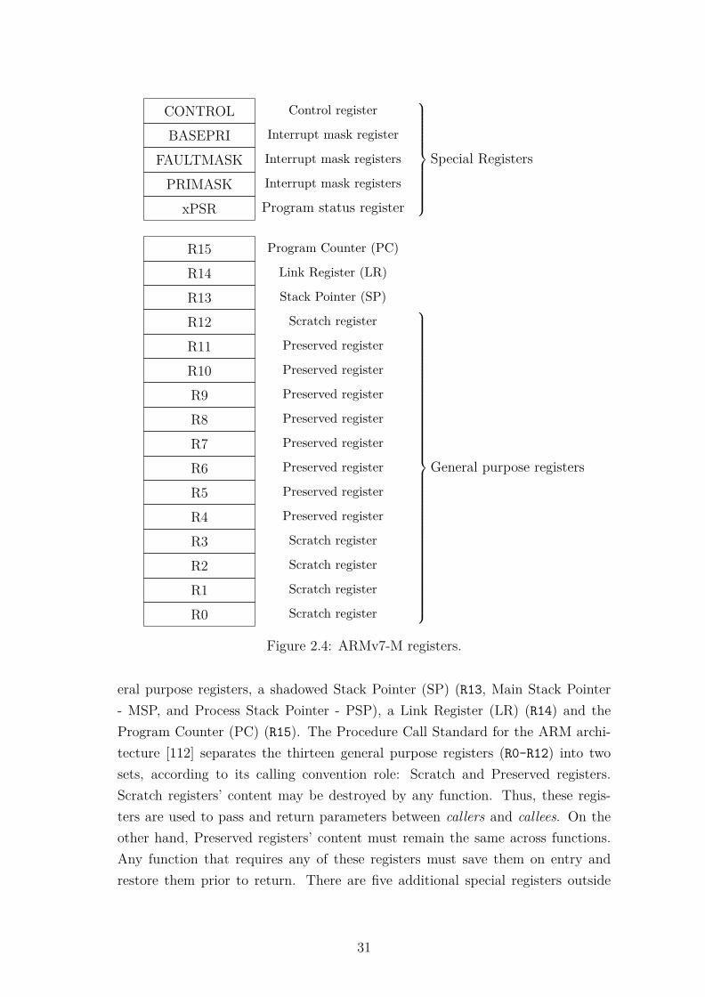
CONTROL Control register
BASEPRI Interrupt mask register
FAULTMASK Interrupt mask registers
PRIMASK Interrupt mask registers
xPSR Program status register
Special Registers
R15 Program Counter (PC)
R14 Link Register (LR)
R13 Stack Pointer (SP)
R12 Scratch register
R11 Preserved register
R10 Preserved register
R9 Preserved register
R8 Preserved register
R7 Preserved register
R6 Preserved register
R5 Preserved register
R4 Preserved register
R3 Scratch register
R2 Scratch register
R1 Scratch register
R0 Scratch register
General purpose registers
Figure 2.4: ARMv7-M registers.
eral purpose registers, a shadowed Stack Pointer (SP) (R13, Main Stack Pointer- MSP, and Process Stack Pointer - PSP), a Link Register (LR) (R14) and theProgram Counter (PC) (R15). The Procedure Call Standard for the ARM archi-tecture [112] separates the thirteen general purpose registers (R0-R12) into twosets, according to its calling convention role: Scratch and Preserved registers.Scratch registers’ content may be destroyed by any function. Thus, these regis-ters are used to pass and return parameters between callers and callees. On theother hand, Preserved registers’ content must remain the same across functions.Any function that requires any of these registers must save them on entry andrestore them prior to return. There are five additional special registers outside
31

0262728293031
N Z C V Q RESERVED
Figure 2.5: ARMv7-M APSR bits.
the register bank: The Program Status Registers (xPSR); three Interrupt relatedregisters, PRIMASK, FAULTMASK and BASEPRI; and the CONTROL register,for privilege mode and stack selection. Figure 2.4 presents the registers in theCortex-M3.
The Program Status Registers (xPSR) is subdivided in three status registers,the Application Status Register (APSR), the Interrupt Program Status Regis-ter (IPSR) and the Execution Program Status Register (EPSR), each respectivelyused for registering and evaluating conditional flags, registering exceptions in Han-dler Mode, and conditional execution specific information storage. The APSR,Figure 2.5, has special prominence because of the condition code flags containedand its role in conditional branching. From the most significant bit (MSB) tothe LSB there is the Negative flag (N), set when an operation’s result in two’scomplement is negative; the Zero flag (Z) set when a operation’s result is zeroor a comparison os equal values; the Carry flag (C), set upon carry conditions;the Overflow flag (V), to assign overflow conditions; and the Q bit, used to flagsaturation situations of the SSAT and USAT instructions.
2.3.1 ARM CoreSight Architecture
As aforementioned, the Cortex-M3 core incorporate powerful debug features pro-vided by the ARM proprietary CoreSight Architecture [106]. The CoreSight Debugand Trace components present on the Cortex-M core, depicted in the Figure 2.6,are used together with software debug tools to provide real-time debug visibility todevelopers and designers. The main components are the Flash Patch Breakpointunit (FPB), the Data Watchpoint and Trace unit (DWT), the InstrumentationTrace Macrocell (ITM), the Embedded Trace Macrocell (ETM) and the TracePort Interface Unit (TPIU) [106]. Each of these components play specific roles inthe debug of the software and they are briefly explained as follows:
• The FPB implements hardware breakpoints, and provides advanced supportfor: breakpoints on code addresses and remapping of instructions or literalslocations from code or system memory to SRAM addresses.
32

• The DWT provides watchpoint support for analyzing and monitoring dataand code. It is composed by several comparators that can be programmedto match memory addresses and/or their content, PC value and numberof clock cycles spent. As a result of the match events it can generate IOsignals, trigger debug states or exception, or forward the event to the ITMto be combined with other debug information.
• The ITM is a trace source unit used to provide printf() style debug sup-port. The ITM logs debug and trace packages from multiple sources, namelysoftware traces and DWT events, and interfaces them to the TPIU, with op-tional added timestamp.
• The ETM is a debug component that enables the reconstruction of thesoftware flow, by tracing the instructions that are executed. Software trac-ing may be started by a DWT event, external inputs or by the Start/Stopcontrol block.
• The TPIU is a debug component that interfaces all the previously describeddebug modules and an external data stream output. The TPIU associatesIDs to the data packets received, synchronizes the packets accordingly withtheir timestamp, and serializes the information to the debug interface (e.g.,JTAG, Serial Wire Debug, etc).
The Cortex-M3 processors integrating the CoreSight architecture support two de-
Debug Connetor
Cortex-M3 Processor
Flash SRAM Peripherals
Microcontroller
TPIUProcessor Core
Internal Bus
ETM
DWT
ITM
FPB
Serial Wire Viewer
Off-chip Trace Port
Figure 2.6: Cortex-M3 CoreSight debug architecture.
33

bug modes: (1) a halting debug mode where core execution is halted for probingand (2) the debug monitor mode, where a debug exception triggers a handlerroutine to perform the necessary debug operations.
2.4 Development Platform
In order to address the research questions proposed in Chapter 1, deploying aDBTor for COTS low-end embedded system foreseeing hardware support withoutarchitectural intrusiveness, and towards the target platform selected in this chap-ter, a platform that integrates a Cortex-M3 processor is required. The explorationof custom hardware extensions claims for platforms including FPGA fabric. Alongthese lines, the required development board fall in the category of a SoC, requiringa hard-core ARMv7-M core (Cortex-M3) plus FPGA fabric.
After probing the available platforms on the market, the Microsemi SmartFu-sion2 SoC was selected. The SmartFusion2 is the Microsemi’s next-generation SoCFPGA, with a hard-core Cortex-M3 processor and panoply of peripherals, reliableflash-based FPGA fabric and Advanced Microcontroller Bus Architecture (AMBA)compliant . Microsemi advertises it as the "low power industry leader" (10× lowerstatic power, half of the total power consumption) and preach the SoC’s reliabilityfeatures as the definitive solution for application with high level of criticality (e.g.,defense, aviation, medical) [113].
The microcontroller subsystem (MSS) of the SoC includes the Cortex-M3 proces-sor, running up to 166 MHz and supporting low-power modes; 8 KB instructioncache; up to 5 MB embedded SRAM and 512 MB on-chip embedded Non-VolatileMemory (eNVM); a panoply of peripherals, e.g., Serial Peripheral Interface (SPI),universal asynchronous receiver-transmitter (UART), I2C, DDR Bridges, timers,etc; 5G transceivers with PCI Express endpoints; and dedicated Fabric InterfaceController (FIC) modules to exchange control and data with the FPGA side ofthe SoC [113,114].
The FPGA fabric has up to 150K logic elements (LE) of four input, up to 240digital signal processing (DSP) blocks and configurable large and small blocksof SRAM (up to 240 KB and 4 MB, respectively). To achieve the required re-liability for safety critical and mission critical systems, the SmartFusion2 SoCoffers state-of-the-art design and data security features: physically uncloneable
34
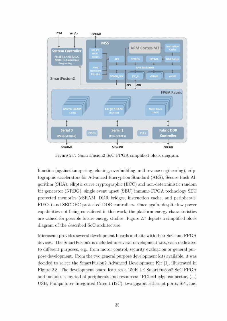
FPGA Fabric
Serial 0
(PCIe, SERDES)
SmartFusion2
Serial 1
(PCIe, SERDES)
Fabric DDR
ControllerOSCs PLLs
Micro SRAM(64x18)
Micro SRAM(64x18)
Micro SRAM(64x18)
Micro SRAM(64x18)
Micro SRAM(64x18)
Micro SRAM(64x18)
Large SRAM(1024x18)
Large SRAM(1024x18)
Large SRAM(1024x18)
Large SRAM(1024x18)
Large SRAM(1024x18)
Large SRAM(1024x18)
Math Block(18x18)
Math Block(18x18)
Math Block(18x18)
Math Block(18x18)
Math Block(18x18)
Math Block(18x18)
MSS
COMM_BLK
ARM Cortex-M3
AES256, SHA256, ECC, NRBG, In-Application
Programing, …
System Controller SPI, I2C,UART, Timers
Hard Hardware Periphs.
AHB Bus Matrix
FIC_0FIC_0
APB
eNVMeSRAM
DDR Bridge
InstructionCache
HPDMASYSREG
Serial I/O Serial I/O DDR I/O
JTAG SPI I/O
APB AHB
USER I/O
Figure 2.7: SmartFusion2 SoC FPGA simplified block diagram.
function (against tampering, cloning, overbuilding, and reverse engineering), crip-tographic accelerators for Advanced Encryption Standard (AES), Secure Hash Al-gorithm (SHA), elliptic curve cryptographic (ECC) and non-deterministic randombit generator (NRBG); single event upset (SEU) immune FPGA technology SEUprotected memories (eSRAM, DDR bridges, instruction cache, and peripherals’FIFOs) and SECDEC protected DDR controllers. Once again, despite low powercapabilities not being considered in this work, the platform energy characteristicsare valued for possible future energy studies. Figure 2.7 depicts a simplified blockdiagram of the described SoC architecture.
Microsemi provides several development boards and kits with their SoC and FPGAdevices. The SmartFusion2 is included in several development kits, each dedicatedto different purposes, e.g., from motor control, security evaluation or general pur-pose development. From the two general purpose development kits available, it wasdecided to select the SmartFusion2 Advanced Development Kit [1], illustrated inFigure 2.8. The development board features a 150K LE SmartFusion2 SoC FPGAand includes a myriad of peripherals and resources: "PCIex4 edge connector, (...)USB, Philips Inter-Integrated Circuit (I2C), two gigabit Ethernet ports, SPI, and
35
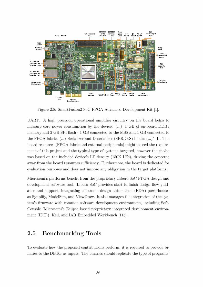
SmartFusion2 SoC FPGA Advanced Development Kit Quickstart Guide
2
• Two FMC connectors with HPC/LPC pinout for expansion• PCIe x4 edge connector• RJ45 interface for 10/100/1000 Ethernet• USB micro-AB connector• Headers for I2C, SPI, GPIOs• FTDI programmer interface to program the external SPI flash• JTAG/SPI programming interface• RVI header for application programming and debug• Flashpro programming header• Embedded trace macro (ETM) cell header for debug • QUAD 2:1 MUX/DEMUX high bandwidth bus switch• Dual in-line package (DIP) switches for user application • Push-button switches and LEDs for demo purposes• Current measurement test points
Development Board Callout
This kit has on-board programmer and does not require a standalone FlashPro hardware to program the board.FlashPro5 programming procedure needs to be used to program the device using on-board programmer.
For more information, refer to the Embedded flashpro5 programming procedures.
Figure 2.8: SmartFusion2 SoC FPGA Advanced Development Kit [1].
UART. A high precision operational amplifier circuitry on the board helps tomeasure core power consumption by the device. (...) 1 GB of on-board DDR3memory and 2 GB SPI flash - 1 GB connected to the MSS and 1 GB connected tothe FPGA fabric. (...) Serializer and Deserializer (SERDES) blocks (...)" [1]. Theboard resources (FPGA fabric and external peripherals) might exceed the require-ment of this project and the typical type of systems targeted, however the choicewas based on the included device’s LE density (150K LEs), driving the concernsaway from the board resources sufficiency. Furthermore, the board is dedicated forevaluation purposes and does not impose any obligation in the target platforms.
Microsemi’s platforms benefit from the proprietary Libero SoC FPGA design anddevelopment software tool. Libero SoC provides start-to-finish design flow guid-ance and support, integrating electronic design automation (EDA) powerhousesas Synplify, ModelSim, and ViewDraw. It also manages the integration of the sys-tem’s firmware with common software development environment, including Soft-Console (Microsemi’s Eclipse based proprietary integrated development environ-ment (IDE)), Keil, and IAR Embedded Workbench [115].
2.5 Benchmarking Tools
To evaluate how the proposed contributions perform, it is required to provide bi-naries to the DBTor as inputs. The binaries should replicate the type of programs’
36

behavior that run in the source architectures. Since this is also the purpose of anybenchmark suit - to mimic a typical workload of a system - it was decided to usea benchmark’s binaries as the source binaries for the DBTor.
2.5.1 BEEBS
Bristol Energy Efficiency Benchmark Suite (BEEBS) is a set of ten benchmarksported from other suites, selected accordingly with its type of operations (Branch-ing, Memory intensity, Integer and Floating Point Operations), its applicabilityfor resource-constrained embedded systems and required porting effort, in orderto evaluate the energy consumption characteristics of the target platform [116].It was proposed by Pallister et. al at the university of Bristol, United Kingdomand is freely available. Details on the benchmarking applications can be found inthe documentation [116]. This benchmark suite, was assembled with benchmarksfrom the MiBench, DSPstone, WCET, Livermore Fortan Kernels, Dhrystone andMediaBench suites, accordingly to their characteristics, suitability to bare-metaldeployment and type of operation variety (Branching, Memory, Integer operations,Floating Point operations). Despite created to evaluate energy consumption onembedded processors, the suite was tailored with the same characteristics of theselected source legacy system: bare-metal implementation, no filesystem, excludeperipherals and small memory footprint. Thus this benchmarking suite was used asa sample set of source application binaries. The source code of the benchmark wascompiled to the source architecture, the MCS-51, and used as the source binaries,in order to validate the DBTor’s correctness and test the proposed contributions.
The benchmarks were compiled using the IAR C/C++ compiler [117], with theoptimizations set to Medium for executable size purposes. The optimizations per-formed in Medium are:
• Variables live-dead analysis and optimization
• Dead code elimination
• Redundant label elimination
• Redundant branch elimination
• Code hoisting
• Register content analysis and optimization
37
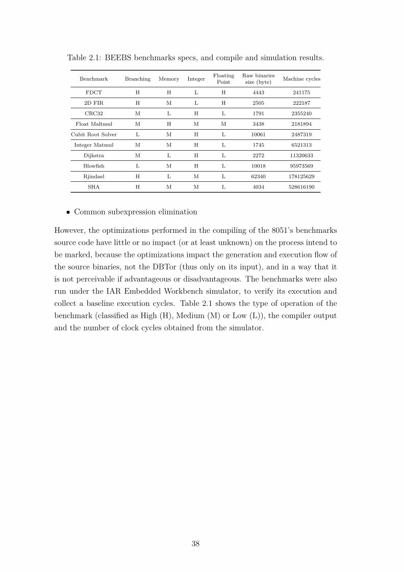
Table 2.1: BEEBS benchmarks specs, and compile and simulation results.
Benchmark Branching Memory Integer FloatingPoint
Raw binariessize (byte) Machine cycles
FDCT H H L H 4443 241175
2D FIR H M L H 2505 222187
CRC32 M L H L 1791 2355240
Float Maltmul M H M M 3438 2181894
Cubit Root Solver L M H L 10061 2487319
Integer Matmul M M H L 1745 6521313
Dijkstra M L H L 2272 11320633
Blowfish L M H L 10018 95973569
Rjindael H L M L 62340 178125629
SHA H M M L 4034 528616190
• Common subexpression elimination
However, the optimizations performed in the compiling of the 8051’s benchmarkssource code have little or no impact (or at least unknown) on the process intend tobe marked, because the optimizations impact the generation and execution flow ofthe source binaries, not the DBTor (thus only on its input), and in a way that itis not perceivable if advantageous or disadvantageous. The benchmarks were alsorun under the IAR Embedded Workbench simulator, to verify its execution andcollect a baseline execution cycles. Table 2.1 shows the type of operation of thebenchmark (classified as High (H), Medium (M) or Low (L)), the compiler outputand the number of clock cycles obtained from the simulator.
38

Chapter 3
Designing a Dynamic BinaryTranslator
The development of any tool is a complex task that requires knowledge, time andresources. Whenever possible existing tools should be used, but when they do notcomply with the project requirements, then an implementation from scratch is re-quired. This chapter presents the general architecture of a DBT engine, identifyingthe functionalities of each component and exposing how they relate and interactin the architecture. Then the design requirements are highlighted and the imple-mentation characteristics that favor such requirements are enumerated, prior topresent the design decision taken during implementation. The rest of the chapteris organized as follows: the state of the art is revisited in section 3.1; the genericarchitecture of a DBTor is introduced in section 3.2 and the design requirementsin section 3.3; The deployment insights and the chapter’s conclusions in sections3.4 and 3.5 respectively.
3.1 Introduction
From the literature presented in Chapter 1, many DBT engines may be examinedin order to extract the key elements of the architecture and important deploymentideas to successful implement one. In [84], Probst implements a DBTor with anunderlaying OS support for application-level emulation. This type of emulationrequires system calls conversion from source to the target OS. This procedure isnot necessary on a system-level emulation. The author describes the overall ar-
39

chitecture of the translator, referring to the basic unit of translation which is a"sequence of instruction likely to be executed as a whole. It has one entry point,and one or more exit point". This translation unit for bibliography coherence pur-poses [44, 45, 69, 74, 88], will be identified from now on as a Basic Block (BB). Headdresses the handling of Operands from architecture to architecture, and architec-ture details that must be handled upon translation, e.g., endianess, immediate size,address space, page size and register mapping. He also introduces the handling ofself modifiable and dynamic loaded code. Despite the code being available underGNU general-purpose language (GPL), it targets high-performance architecturessuch as Alpha, PowerPC and i386.
BOA [42] also describes the architecture of a DBTor for desktop application. Alt-man et al. pretend to optimize PowerPC applications through continuous codeprofiling to explore ILP execution on a VLIW architecture. This work targetsmultiple Gigahertz execution and single-source/single-target translation, thus notsuitable for using in embedded systems. Moreover, code optimization and tracingstrategies used are also very heavy to run on such resource-constrained devices.
In [67], Ling et al. describe their approach to DBT on remote thin clients. Theyanalyze the normal DBTor workflow and point the translation misses as a hugepenalty inducting factor, proposing to use a client/server distributed architectureto split the functionalities of the translator and expand the code caching capabil-ities. This approach requires a support network layer, and the thin client, despitethe "thin" is a Desktop computer based on a Inter Celeron processor.
Bellard [86] presented the internals of QEMU, a known machine emulator that usesan original and portable binary translation to accelerate the emulation process. Inthis paper Bellard details how the portable translator was conceived to use anIntermediary Representation, taking advantage of cross-compiler tricks to achievea portable and retargetable three-address micro operations IR.
The work of [118] describes the optimizations that can and should be performedon a resourceable and retargetable DBTor. The authors identify several overheadsources inherent to DBT (translation overhead, inefficient generated code, codeloading, etc) and propose several optimizations such as BB linking, CC handlingoptimizations and techniques to benefit from multi core execution.
The aforementioned contributions present the architectural requirements and con-cerns upon the development of a DBT. The authors have also identified sev-
40
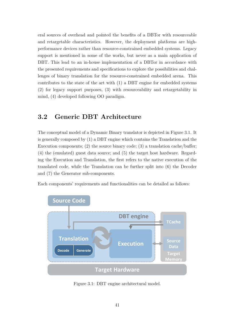
eral sources of overhead and pointed the benefits of a DBTor with resourceableand retargetable characteristics. However, the deployment platforms are high-performance devices rather than resource-constrained embedded systems. Legacysupport is mentioned in some of the works, but never as a main application ofDBT. This lead to an in-house implementation of a DBTor in accordance withthe presented requirements and specifications to explore the possibilities and chal-lenges of binary translation for the resource-constrained embedded arena. Thiscontributes to the state of the art with (1) a DBT engine for embedded systems(2) for legacy support purposes, (3) with resourceability and retargetability inmind, (4) developed following OO paradigm.
3.2 Generic DBT Architecture
The conceptual model of a Dynamic Binary translator is depicted in Figure 3.1. Itis generally composed by (1) a DBT engine which contains the Translation and theExecution components; (2) the source binary code; (3) a translation cache/buffer;(4) the (emulated) guest data source; and (5) the target host hardware. Regard-ing the Execution and Translation, the first refers to the native execution of thetranslated code, while the Translation can be further split into (6) the Decoderand (7) the Generator sub-components.
Each components’ requirements and functionalities can be detailed as follows:
Target Memory
Target Hardware
Source Data
DBT engine
ExecutionTranslation
Decode Generate
Source Code
TCache
Figure 3.1: DBT engine architectural model.
41
• DBT engine is the representation of the kernel responsible for the DBToperations. It can be understood as the "heart" of the DBTor since it connectsand coordinates all the modules involved in the translation and executionof the guest programs. This imperative component must be aware of theavailable hosting platform resources where it will be running. It hosts thenext two main components in analysis, the Translation and the Executionblocks.
• Translation is the module that handles the transformation of the source bi-naries into target machine executable code. This component receives sourcebinaries as inputs, and outputs to a "translation cache", which will be intro-duced afterwards in this listing. Broadly speaking, the translator’s executionis spent between the Translation and the Execution, so this is one of its corecomponents. The code translation is achieved by reading the source binaries,one instruction at a time, decoding its meaning and generating target ma-chine code to reproduce its behavior. These transformations can be achievedthrough different ways, however in order to decouple the source and targetimplementation-specific parts, two other sub-components are needed: theDecoder and Generator. Since the source/target architecture bridging ishandled in this component, it comprises most of machine specific supportcode, i.e., the source ISA decoding and the target machine code generation,respectively.
• Decoder is one of the Translation sub-components. This component ispurely dedicated to interface the source binaries, thus it is source specific.It must distinguish each of the source ISA instructions and decode theirmeaning in order to transmit it to its "pair" component, the Generator. Thedecoding of the instructions can be implemented through different techniquesand algorithms, but in order to not affect non-source related components,there must be some sort of common interface between this component andthe Generator. In doing so„ modifications on the source-specific decodinghave no impact on the target specific code generation, independently of theimplementation. It is common to use an IR between host and guest ISAs toperform such interface and isolation.
• Generator is the mentioned pair of the Decoder component, dedicated togenerate target machine code. Contrary to a code simulator, the generatormust output executable code to the target machine based on parameters
42

transmitted by the Decoder. The transfered information contains data rela-tive to the operation type, operands, immediate values, branch destination,etc. The generated code must replicate the exact behavior of the source code,otherwise the execution flow will be lost. This is the Translator’s target ISAspecific component, thus must be in accordance with the host hardware inuse. It is the major part of the DBTor to be modified in case of porting toother target architecture.
• Tcache or translation buffer, together with the Generator, is one of thecomponents that mainly differentiates a translator from a simulator, and it iswhere the translated code is stored before being executed. This componentmust be allocated on a section of the host machine’s memory with writeaccess and execution privileges. It must implement content management andreplacement mechanisms to accommodate the incoming translations from theGenerator and keep track of the stored BBs.
• Execution is not a tangible component (i.e., with implementation), butrather the native execution of the generated code. However, and as in-troduced in the "Translation" description, the DBT engine is continuouslyswitching between code translation and code execution, thus this componentmust be part of the architectural mode. The code is executed one TBB ata time and after completion, the Execution gives its way to the Translation,successively.
• Source Binary Code represents the binaries that were generated to beoriginally executed in the source processor architecture. This is the codeintended to run on another architecture than the one it was compiled orassembled for. The code format can be raw binary, .hex, or any executablefile format such as .elf or .exe, depending on supported formats. Theprovenience of the code may also be diversified, e.g., from a non-volatilememory, received through a communication interface, or gathered from thenetwork. These are all applications specific details, however due to codetranslation requiring quick and repetitive accesses to the code, some sort ofmemory hierarchy structure, like a cache or a buffer is required to reduceaccess latencies.
• Source Data or Guest Data is the guest related memory emulation support.It contains items such as the guest Program Counter and other special reg-isters, execution information and the emulated guest memory. This memory
43
must be accessible either during Translation or during Execution stages.
• Host Hardware or Target machine is the processor where the DBTor runs,that is to say, the architecture for what the DBTor must be compiled for, aswell as the target machine for the code obtained from the Generator. Theaffinity between this machine and the Source ISA establishes most of theimplementation requirements and specifications.
When considering a novel implementation, the presented elements were classifiedas "source/target variable" or "DBTor intrinsic. The elements
(a) DBT Engine;
(b) Execution;
(c) Source Binary;
(d) Translation Cache;
fall into the "DBTor intrinsic" category because their architectural design require-ments do not depend on the guest or host architectures. Thus their implementa-tion and integration should be the same among different Source ISAs and TargetHardwares.
The remaining elements, i.e.,
(a) Decoder;
(b) Generator;
(c) Source Data support;
are ISA specific, thus considered "source/target variable" and require re-writingeffort to comply with different ISAs. Generally, every implementation should con-sider the target’s available platform resources.
3.3 Requirements and Design Decisions
The implementation requirements that must be present upon architecture designand implementation of the DBTor were gathered within the scope of this work.Such requirements comprise:
44

1. DBT targeting resource-constrained embedded systems. The system deploy-ment must be kept minimalistic for a low memory footprint, avoiding heavyprocessing algorithms, complex algorithms and making the most commoncase fast.
2. A system level DBTor for full system emulation. In these types of translators,the DBTor does not provide any system support, contrary to the applicationlevel translators. This implies that if the source binaries where compiled foran OS, then the full system image must be loaded and translated.
3. There are no dedicated reasons that justify the use of an OS (i.e., paral-lelizeable tasks, concurrent accesses to computing resources or peripherals,network stack or user interface). Thus, the DBTor should be a bare-metalsolution, sparing unnecessary resources use by the OS.
4. The DBTor should provide data support structures for the source binariesand translation fragments.
5. Resourceability and retargetability are two major requirements. Althoughthe variability associated with these concepts might penalize the perfor-mance, considering the application range and the type of source binariesinvolved, some performance loss is acceptable. The benefits of an architec-ture designed with those in mind are ease of modification, severe code reuseand enforced correctness by design upon supporting new ISAs.
6. High level abstraction without neglecting code efficiency, inherited from theprevious requirement.
3.4 Deployment Insight
With the exposed requirements in mind, C++ was the elected programing languageto implement the system. It is a proven OO programing language with efficientmachine-code generation, and inherent variability management and code reusemechanism like Inheritance and Polymorphism. The penalty induced by thedynamic characteristics of the language might be contained according to Cardoso[119] and static virtual table analysis [120].
The algorithm was implemented from scratch with re-usability in mind. The vari-ability points where identified and managed through C++ features and techniques,
45
in order to ease DBTor’s configuration and multi source/target translations sup-port. The following descriptions will detail how the module’s variability was han-dled during implementation. Despite presenting implementation details, the pur-pose of this section is towards variability management techniques used and not asan implementation guide of the project.
3.4.1 Retargetability Support
In order to achieve easy retargetability, the source and target specific implemen-tation must be decouple from each other. This approach has three implications:
1. The DBTor’s kernel functionalities must be apart from the source/target’simplementations in order to avoid dependencies among the DBTor’s genericfunctionalities and modifications performed to the source/target ISAs imple-mentations;
2. Source and target functionalities and implementations must be independentfrom each other, avoiding modification to both source and target implemen-tations in case of a new source or target ISA support.
3. An IR interface between the source and target ISAs for information exchangebetween the Source instructions’ Decoder and the Target’s code Generator.
Intermediate Representation
A QUEMU-based IR [86] was used for its simplicity. The IR is a defined set orvirtual instructions which must be output by the Source architecture Decoder,and must be ported to the Target architecture generator. Each micro operationis represented by a C++ function that must generate target machine code thatreproduces the behavior it represents. This equivalence must be established manu-ally or automatically, by mean of an external tool, but ISA automatic pairing fallsoutside the scope of this work. The virtual ISA of the IR is based on a 3-addressmachine, with the following operations (Listing 3.1):
46

1 //conditional IR instructions2 virtual void gen_cmp(uint8_t SReg1, uint8_t SReg2) = 0;3 virtual void gen_cje(uint8_t SReg1, uint8_t SReg2, uint8_t offset) = 0;4 virtual void gen_cjne(uint8_t SReg1, uint8_t SReg2, uint8_t offset) = 0;56 //branch IR instructions7 virtual void gen_writePCreg(uint8_t SReg) = 0;89 //data transfer IR instructions
10 virtual void gen_mov(uint8_t DReg, uint8_t SReg) = 0;11 virtual void gen_movi8(uint8_t DReg, uint8_t imm) = 0;12 virtual void gen_movi16(uint8_t DReg, uint16_t imm) = 0;13 virtual void gen_movi32(uint8_t DReg, uint32_t imm) = 0;1415 //load from emmulated memory IR instructions16 virtual void gen_ld8(uint8_t DReg, unsigned int imm) = 0;17 virtual void gen_ld16(uint8_t DReg, unsigned int imm) = 0;1819 //store to emmulated memory IR instructions20 virtual void gen_st8(unsigned int imm, uint8_t SReg) = 0;21 virtual void gen_st16(unsigned int imm, uint8_t SReg) = 0;2223 //alu IR instructions24 virtual void gen_add(uint8_t DReg, uint8_t SReg1, uint8_t SReg2) = 0;25 virtual void gen_sub(uint8_t DReg, uint8_t SReg1, uint8_t SReg2) = 0;2627 virtual void gen_div(uint8_t DReg, uint8_t SReg1, uint8_t SReg2) = 0;28 virtual void gen_mul(uint8_t DReg, uint8_t SReg) = 0;2930 virtual void gen_not(uint8_t DReg, uint8_t SReg) = 0;31 virtual void gen_or(uint8_t DReg, uint8_t SReg) = 0;32 virtual void gen_and(uint8_t DReg, uint8_t SReg) = 0;33 virtual void gen_xor(uint8_t DReg, uint8_t SReg) = 0;3435 virtual void gen_shr(uint8_t DReg, uint8_t SReg1, uint8_t SReg2) = 0;36 virtual void gen_shl(uint8_t DReg, uint8_t SReg1, uint8_t SReg2) = 0;
Listing 3.1: IR micro operations declared as pure virtual methods.
The arguments present in each of the above micro operations functions representeither an immediate value (e.g., offset, imm) or a temporary working register(e.g., DReg, SReg). The immediate arguments are literals extracted from the sourcebinaries while the temporary working registers refer to target machine’s generalpurpose registers used to emulate the 3-address machine. This approach was used
47

instead of direct register mapping to favor portability to target architectures withlow general purpose registers count.
The porting of these IR will be introduced in the next chapter.
Source and Target separation
In order to provide the mentioned separation between Source and Target imple-mentations, while promoting code reuse, the C++ concepts of Inheritance andAbstract Base classes were resorted. Defining a base class Translator that im-plements all the "DBTor intrinsic" functionalities as base methods promotes itsreuse for every instance. Additionally, the base class also establishes the port-ing interfaces as pure virtual methods. With this last mechanism is forced theimplementation of the IR virtual instructions and the Source and Target specificmethods, while blocking the declaration of a Translator object without them. Thesource-related virtual method is the decode() and the target-related are the im-plementation of each IR micro operations, which represent the Generator.
In order to port the DBTor, a derived class of the Translator must implement thesource and target ISA methods, and then it is ready to be compiled for the targetarchitecture. This method allows flexibility during implementation, while respect-ing the general guidelines (main class methods). Although this type of dynamicpolymorphism is known to cause performance penalties, since there is a singleDerived class, the penalty can be contained through "virtual table elimination"compiler options [121,122].
Below in Listing 3.2 is presented the header file of theTranslator class, from whichthe composing elements will be explained ahead in this chapter. The abbreviatedIR micro operations were presented in the code snippet before and removed hereto avoid repetition.
1 #ifndef TRANSLATOR_H2 #define TRANSLATOR_H34 #include "TransFlushCache.h"5 #include "CBuffer.h"6 #include "types.h"78 typedef struct SourceEnvironment {9 SOURCE_PC PC;
10 uint8_t * dataMem;
48

11 } SourceEnvironment;12 class CTranslator13 {14 protected:15 SOURCE_MEM_BASE * pSourceProgMem; //source program pointer to the16 //beginning of the loaded binaries17 CTransFlushCache transCache; //Translation cache instance18 CBuffer codeCache; //CCache with the source in use1920 uint8_t volatile * currBBExecPtr; //pointer for the BB during decode21 SourceEnvironment volatile env; //source enviroment data struct2223 //translation support variables24 bool volatile eoExec; //End of Execution flag25 bool volatile eoBB; //End of Basic Block flag2627 //Pure Virtual methods28 virtual void envReset(void) = 0; //implemented by the child class29 virtual void decode(void) = 0; //decode and fetch instruction30 //into a set of micro Ops.31 virtual void gen_prolog(void) = 0;32 virtual void gen_epilog(void) = 0;3334 //Virtual IR interfaces35 /*36 ...37 */38 public:39 CTranslator(int Ccache_size, int TcacheSize); //constructor, with40 //initialization41 //parameters42 ~CTranslator(void);4344 int reloadTranslator(void * sourCodeAddr , int sourCodeSize ,int
exit_address); //initialization and reset45 //method46 int sourceCodeLoader(void * programStart); //load source binaries47 //into codeCache4849 int runDBT(void); //method that runs the DBT engine50 };5152 #endif
Listing 3.2: Translator class header file.
49
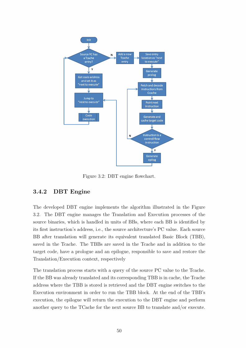
Figure 3.2: DBT engine flowchart.
3.4.2 DBT Engine
The developed DBT engine implements the algorithm illustrated in the Figure3.2. The DBT engine manages the Translation and Execution processes of thesource binaries, which is handled in units of BBs, where each BB is identified byits first instruction’s address, i.e., the source architecture’s PC value. Each sourceBB after translation will generate its equivalent translated Basic Block (TBB),saved in the Tcache. The TBBs are saved in the Tcache and in addition to thetarget code, have a prologue and an epilogue, responsible to save and restore theTranslation/Execution context, respectively
The translation process starts with a query of the source PC value to the Tcache.If the BB was already translated and its corresponding TBB is in cache, the Tcacheaddress where the TBB is stored is retrieved and the DBT engine switches to theExecution environment in order to run the TBB block. At the end of the TBB’sexecution, the epilogue will return the execution to the DBT engine and performanother query to the TCache for the next source BB to translate and/or execute.
50
The PC value is affected by conditional branches and function calls during theexecution of the TBB. If the source PC is not yet translated, then a new translationmust be executed. This is started by adding a new entry to the Tcache for thenew BB and saving the address (for later execution) where the generated code ofthe TBB will start. Then the prologue is stored in the Tcache and the Translationprocess starts its loop until fetching a control flow instruction. Each instructionis decoded and translated individually and the PC updated to the next value,accordingly with the instruction length. A control flow instruction determinesthe end of the Translation cycle and the generation of the TBB’s epilogue. Thepreviously saved TBB location address is now used by the DBT engine to switchto the execution of the recently translated BB.
3.4.3 Translation to Execution Switch
A seamless and portable Translation/Execution context switch is supported bythe C/C++ execution environment, handled as a function call and return. Whenswitching from Translation to Execution, the TBB’s start address is casted as afunction pointer and a call is performed through it. This method ensures thatthe C compiler will generate the necessary code to jump to the TBB and startits execution. After the function call, the callee, i.e., the TBB, must respectthe target architecture’s application binary interface (ABI) regarding parameterpassing, return address and context saving. These tasks are left to the generatedprologue at the beginning of the TBB. At the end of the TBB, the generatedepilogue will handle the context restore and the return of the values and theexecution to the caller, which is the Translator’s Execution. This is handled like acommon function call and return process. The single porting effort remains on theadaptation of the prologue and the epilogue accordingly with the target’s C++ABI.
1 ...2 //SWITCH TO EXECUTION3 ((void (*)(int*))((int*)(currBBExecPtr+1)))((int *)(env.dataMem));45 //RETURNED TO TRANSLATION6 } while( !eoExec );7 ...
Listing 3.3: Translation to Execution switch code snippet.
51

The Listing 3.3 shows a code snippet of the TBB’s start address casted as afunction, inside the Translation cycle.
3.4.4 Memory Support Structures
There are several memory support structures involved in the process of DBT.The DBTor is a memory intensive system due to the repetitive accesses to thesource binaries and the target code storage and access. Memory support structureslike caches and buffers are used on a two fold way: (1) to cope with memorylatencies associated with accesses and (2) as a storage support entity for data andcode. Additionally, it is required a structure to contain translation related sourcedata (e.g., PC, location of emulated source data memory, etc.), called the sourceenvironment data. The three different used memory support structures used aredetailed in the next paragraphs.
Source Binaries Cache
The Source Binaries Cache, or source code cache (Ccache) purpose is to store thesource program on system memory and set it available byte by byte to the DBTengine upon request. On the embedded DBT context this module exists for severalreasons, such as:
1. Quick access - The binaries are usually stored in flash memories or otherROM technologies, which typically have associated access latencies. Theseaccess costs can be alleviated with the use of a proximity storage buffer onsystem RAM. The designated memory space should be pre-loaded duringDBTor initialization, thus removing the ROM access costs from execution;
2. Size constraints - The source binaries size may not fit on the available systemRAM. This condition may be overcome with the use of external memories orother type of storage alternatives. In order to execute binaries larger thanthe available system memory, the cache is partially loaded and a hit/misscondition verification is assessed during the runtime load() method to fetcha new block of binaries from its external location, leading to the next reason;
3. Flexibility - The source binaries may be loaded from a variety of externallocations such as external Flash memory, the original storage support of
52
the binaries or transfered though any communication interface (e.g., RS-232,Parallel port, SPI, etc). The single porting effort is focused on the load()method, which must implement the interface and the data transfer from theexternal source to the internal storage buffer.
4. Variability management - Because the DBTor always reads the binaries fromthe Source Binaries Cache, the variability associated with supporting multi-ple external binaries’ sources is isolated from the DBTor algorithm. In thisfashion the variability point is reduced to one (load() method), and apartfrom the DBT engine.
For these reasons the Source Binaries Cache was implemented as an individualclass and integrated in the Translator class by Composition.
Translation Cache
The Tcache, also called Fragment cache [98], is the storage entity where the TBBsare stored to be executed. Besides the storage functionalities it relates the originalBBs with the location of the TBBs. This association between source and targetaddresses is essential to DBT process because it records the equivalence betweensource and target PCs, and consequently BB and TBB. Because of its character-istics, this entity requires different features from the Source binaries cache, whichare described bellow:
1. Write and Execution Privileges - In order to store and natively execute ISAsource code (TBBs stores in memory), two conditions must be fulfilled: (a)the memory where the TCache is allocated must be rewritable during run-time and (2) it must have execution privileges. These two condition are notalways simultaneously true, thus, the target candidate must have a memorywith simultaneous write and execution privileges. That is, a target machineimplementing a pure Harvard architecture (with separate program and datamemories) would offer serious obstacles to support DBT.
2. Content Management - The Tcache requires a data structure to manage andlocate the stored TBBs. This has two purposes: (1) check if the queried BBwas already translated and (2) return the location of the TBB. In case of a hit(i.e., the BB was translated and the TBB is stored in the Tcache) the TBB’saddress must be returned to the DBT engine to be executed, otherwise amissis passed to the DBT engine to start a new translation. There are multiple
53

suitable data structure for this purpose, and its complexity and overheadmust be considered. Implementation apart, the Tcache inputs a source PC(i.e., BB base address), which should be used as a unique key to locate theequivalent TBB.
3. Eviction Mechanism - When the Tcache reaches its maximum capacity, itscontent must be evicted in order to accept new TBB. This might be a partialor total eviction (i.e., flush), depending on the implementation, howeverpartial eviction requires coherency enforcement when directly linking BBduring translation, which might contribute with excessive overheads.
In accordance with the approach followed for the Source Binaries Cache, thiscomponent was also implemented as a standalone class and then included in theTranslator class by Composition. In this way different Content Management andEviction Mechanisms can be attempted without modifications to the DBT enginenor the Source and Target specific components.
Source Environment Support
This last support structure is used to accommodate source runtime relevant values,such as the source PC, the location of the source data memory(ies) location(s),special registers and values that must be accessible during either Translation orExecution. Because of this access availability requirement, and since it is used aC++ standard function call procedure to switch between Translation and Execu-tion, it was implemented as a struct in the Translator class. This allows quickdirect accesses from both sides when passed to Execution by reference a functionparameter.
3.4.5 Helper Function Calls
The Helper Functions are a mechanism à la QEMU used to emulate source programbehaviors which do not have a direct translation to target machine code, or aredifficult or impractical to translate. The behavior intended to be emulated isdescribed in a standard C++ functions, which is then compiled and loaded tomemory together with the DBTor. Upon execution (in the Execution context),the helper function call and return must respect the C++ calling convention,and register’s usage as described in the architecture’s ABI. In order to do so,
54

a Helper Function Call generator gen_helper(void (CTranslator::*helper_-function)(void)) is used to generate and assemble the call instructions with thehelper function address. The generated code is stored into the Tcache and duringExecution it performs a conventional function call. This strategy is used for taskssuch as source calls (handling the stack, the return address, parameters, etc), fordebugging and instrumentation purposes and some CISC instructions emulation.The implementation of Helper Functions is left for the target specific porting ofthe translator, and performed according to deployment necessities.
3.5 Conclusions
In this chapter it is explained the requirements and design decisions taken upon theimplementation of a DBTor dedicated to resource-constrained embedded systems.The variability points where identified and its management through C++ featuresexplained. The DBTor description will be completed in the next chapter, wherethe source and target architectures proposed in chapter 2 will be paired and theresulting source-target use-case tested.
55

56

Chapter 4
Case Study: 8051 on Cortex-M3
In order to evaluate the design and attest the operation of the demonstrator isnecessary to proceed to the final part of the implementation of the DBTor, theporting of source and target architectures selected in Chapter 2. This will allow toevaluate DBT on the tightly constrained embedded systems’ domain and explorethe opportunities offered by this technique. The previously established constraintsand decisions regarding the code isolation and ease of portability were followed andthis chapter describes the implementation process of the source and target parts ofthe project, guiding future porting efforts of the DBTor. In the remaining of thischapter, Section 4.1 approaches the source and target specific details of the portingeffort, together with the conditional flags handling. Section 4.2 refers to the testingand verification of the translator and Section 4.3 presents the conclusions of thechapter.
4.1 Pairing the MCS-51 and the ARMv7-M Ar-chitectures
In this section it is demonstrated how the source and target architectures werearticulated together, detailing each architecture’s porting tasks (i.e., MCS-51 andARMv7-M).
The DBTor executable is a C++ object that inherits all the base Translator classmethods and attributes, along with the implementations of all the source andtarget related virtual methods. Aside from the virtual methods implementation,
57
there are additional aspects regarding the porting operations to be considered,namely the target architecture’s ABI. The C++ calling convention and registersusage scheme related to the target architecture must be known in order to mimica native C++ context switch (between Translation and Execution). The targetarchitecture’s ABI encompasses the following information: 1) the return addresslocation and return procedure to follow by the callee; 2) the parameter passingscheme from a caller to the callee; and 3) the architecture’s register usage duringsubroutines’ execution. The relative importance of each topic is addressed asfollows:
1. The first topic concerns the prologue and epilogue of the translator. Thesetwo DBTor’ features must replicate a standard callee entry and exit behavior,so that the Execution of the translator is handled transparently as a regularC++ function. The Procedure Call Standard for the ARM Architecture(AAPCS) [112] designates that subroutine calls use the primitive subroutinecall instruction BL (branch and link), which loads the next value of theprogram counter to the LR and the destination address to the PC. Thecontrol is returned to the callee by transferring the value of the LR to thePC. The prologue of the TBB must preserve the LR value for the epilogueto return the execution to the Translation.
2. The second topic purpose is to ensure parameter passing between Transla-tion and Execution in accordance with the C++ standard, i.e., parameterslocation, size and order. The AAPCS’ information on parameter passing isextensive and detailed, however the information to retain is:
(a) the base standard for passing up to four arguments to a subroutine isin core registers R0 to R4. For more than four arguments, the excess ispassed through the stack;
(b) variables up to 4 bytes are designated to an individual 32-bit generalpurpose register;
(c) the arguments are passed accordingly with the order they are specifiedin the function call;
(d) in C++, an implicit pointer of the base class (this) is included whena method is called and precedes the first user’s argument.
The code snippet in the Listing 3.3 from Chapter 3, displays how the Trans-
58

lation uses a function call to switch to Execution, by casting the TBB startaddress as a function pointer. The function has one argument (the sourcearchitecture data memory pointer), which must be handled in the Executionenvironment accordingly with the described above. Helper functions callsmust also respect the argument passing convention.
3. The last topic guides the choice of registers used in the Execution as tempo-rary or working registers. The ARM architecture distinguishes the generalpurpose core registers as preserved or scratch registers (refer to Figure 2.4).Scratch registers, R0-R3 and R12, may be freely used by the subroutineswithout caring about their previous contents. If any of these registers isrequired after a function call, the caller must save it during the procedurecall. On the other hand, preserved registers’ value must be preserved acrossfunction calls. The callee may use these registers but their content must besaved before use and restored at the end. During interrupts and exceptions,when unexpected context switch occur, scratch registers are automaticallystacked by the architecture in order to prevent them from being lost dur-ing the handler routines. The values are restored upon interrupt/exceptionreturn. Thus, the correct use of registers during Execution must have intoaccount the type of register:
(a) scratch registers (R0-R3, R12) may be used "on demand" and do notinterfere with the Translation’s context;
(b) preserved registers (R4-R11) use requires additional prologue and epi-logue operations for their save and restore;
(c) the calling of helper functions from the Execution side requires thepreservation and restore of scratch registers, if in use.
4.1.1 Source Specific Porting
In this subsection the necessary source architecture porting tasks are described.The porting was grouped in three groups of tasks, and it will be explained togetherwith code snippets that exemplify the implementation.
59
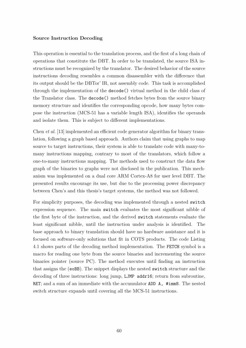
Source Instruction Decoding
This operation is essential to the translation process, and the first of a long chain ofoperations that constitute the DBT. In order to be translated, the source ISA in-structions must be recognized by the translator. The desired behavior of the sourceinstructions decoding resembles a common disassembler with the difference thatits output should be the DBTor’ IR, not assembly code. This task is accomplishedthrough the implementation of the decode() virtual method in the child class ofthe Translator class. The decode() method fetches bytes from the source binarymemory structure and identifies the corresponding opcode, how many bytes com-pose the instruction (MCS-51 has a variable length ISA), identifies the operandsand isolate them. This is subject to different implementations.
Chen et al. [13] implemented an efficient code generator algorithm for binary trans-lation, following a graph based approach. Authors claim that using graphs to mapsource to target instructions, their system is able to translate code with many-to-many instructions mapping, contrary to most of the translators, which follow aone-to-many instructions mapping. The methods used to construct the data flowgraph of the binaries to graphs were not disclosed in the publication. This mech-anism was implemented on a dual core ARM Cortex-A8 for user level DBT. Thepresented results encourage its use, but due to the processing power discrepancybetween Chen’s and this thesis’s target systems, the method was not followed.
For simplicity purposes, the decoding was implemented through a nested switchexpression sequence. The main switch evaluates the most significant nibble ofthe first byte of the instruction, and the derived switch statements evaluate theleast significant nibble, until the instruction under analysis is identified. Thebase approach to binary translation should have no hardware assistance and it isfocused on software-only solutions that fit in COTS products. The code Listing4.1 shows parts of the decoding method implementation. The FETCH symbol is amacro for reading one byte from the source binaries and incrementing the sourcebinaries pointer (source PC). The method executes until finding an instructionthat assigns the (eoBB). The snippet displays the nested switch structure and thedecoding of three instructions: long jump, LJMP addr16; return from subroutine,RET; and a sum of an immediate with the accumulator ADD A, #imm8. The nestedswitch structure expands until covering all the MCS-51 instructions.
60
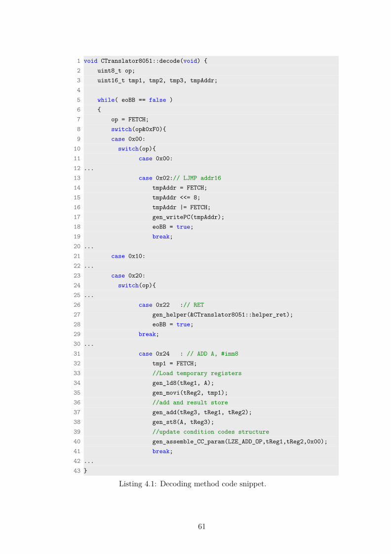
1 void CTranslator8051::decode(void) {2 uint8_t op;3 uint16_t tmp1, tmp2, tmp3, tmpAddr;45 while( eoBB == false )6 {7 op = FETCH;8 switch(op&0xF0){9 case 0x00:
10 switch(op){11 case 0x00:12 ...13 case 0x02:// LJMP addr1614 tmpAddr = FETCH;15 tmpAddr <<= 8;16 tmpAddr |= FETCH;17 gen_writePC(tmpAddr);18 eoBB = true;19 break;20 ...21 case 0x10:22 ...23 case 0x20:24 switch(op){25 ...26 case 0x22 :// RET27 gen_helper(&CTranslator8051::helper_ret);28 eoBB = true;29 break;30 ...31 case 0x24 : // ADD A, #imm832 tmp1 = FETCH;33 //Load temporary registers34 gen_ld8(tReg1, A);35 gen_movi(tReg2, tmp1);36 //add and result store37 gen_add(tReg3, tReg1, tReg2);38 gen_st8(A, tReg3);39 //update condition codes structure40 gen_assemble_CC_param(LZE_ADD_OP,tReg1,tReg2,0x00);41 break;42 ...43 }
Listing 4.1: Decoding method code snippet.
61
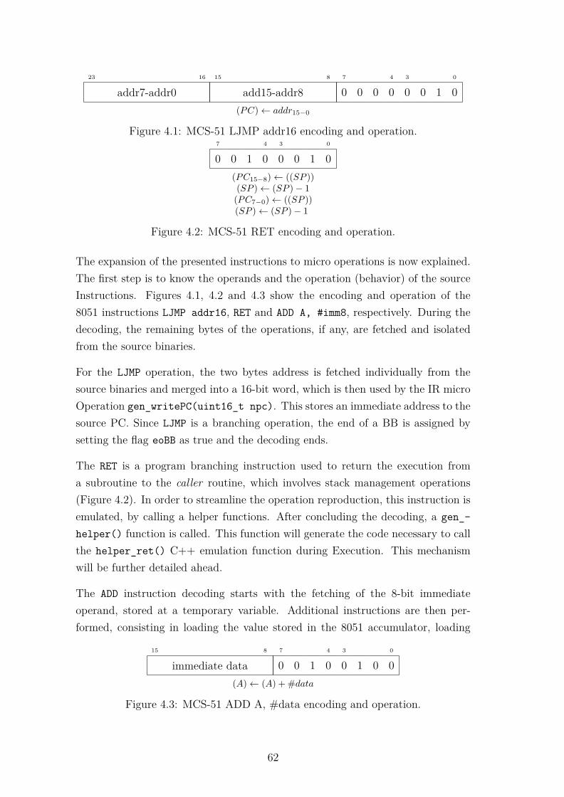
03478151623
addr7-addr0 add15-addr8 0 0 0 0 0 0 1 0(PC)← addr15−0
Figure 4.1: MCS-51 LJMP addr16 encoding and operation.7 34 0
0 0 1 0 0 0 1 0(PC15−8)← ((SP ))(SP )← (SP )− 1
(PC7−0)← ((SP ))(SP )← (SP )− 1
Figure 4.2: MCS-51 RET encoding and operation.
The expansion of the presented instructions to micro operations is now explained.The first step is to know the operands and the operation (behavior) of the sourceInstructions. Figures 4.1, 4.2 and 4.3 show the encoding and operation of the8051 instructions LJMP addr16, RET and ADD A, #imm8, respectively. During thedecoding, the remaining bytes of the operations, if any, are fetched and isolatedfrom the source binaries.
For the LJMP operation, the two bytes address is fetched individually from thesource binaries and merged into a 16-bit word, which is then used by the IR microOperation gen_writePC(uint16_t npc). This stores an immediate address to thesource PC. Since LJMP is a branching operation, the end of a BB is assigned bysetting the flag eoBB as true and the decoding ends.
The RET is a program branching instruction used to return the execution froma subroutine to the caller routine, which involves stack management operations(Figure 4.2). In order to streamline the operation reproduction, this instruction isemulated, by calling a helper functions. After concluding the decoding, a gen_-helper() function is called. This function will generate the code necessary to callthe helper_ret() C++ emulation function during Execution. This mechanismwill be further detailed ahead.
The ADD instruction decoding starts with the fetching of the 8-bit immediateoperand, stored at a temporary variable. Additional instructions are then per-formed, consisting in loading the value stored in the 8051 accumulator, loading
0347815
immediate data 0 0 1 0 0 1 0 0(A)← (A) + #data
Figure 4.3: MCS-51 ADD A, #data encoding and operation.
62
the immediate data to a temporary register, perform the sum and store the resultsback to the Accumulator. The IR micro operations used here are:
• gen_ld8(uint8_t DReg, unsigned int imm);
• gen_movi(uint8_t DReg, uint32_t imm);
• gen_add(uint8_t DReg, uint8_t SReg1, uint8_t SReg2);
• gen_st8(unsigned int imm, uint8_t SReg);
These micro operations were employed accordingly with the described operationof the instruction. There is one additional action not expressed in the instruc-tion operation depicted in Figure 4.3, which is the condition codes update. Thisoperation may only be performed during the execution of the instruction, sincethe CC values depend upon the result of the operation. To obtain this dynamicevaluation, a dedicated operation gen_assemble_CC_param() is used to preservethe operands and the operation on a dedicated structure during Execution. Thisstructure will then be used by another helper function, in order to emulate theoperation and update the correct CCs. This is the mechanism used to handle theCCs for every instruction that affects these flags, and will also be further detailedahead in this chapter. The decode() might following other implementation algo-rithms, as long as the code generation is achieved through the use of the availablemicro operations, the architecture design is respected and the engineering effort isminimal, thanks to the adopted C++ strategy.
Source Complementary Memory
In order to support the source architecture’s binaries execution, guest architec-tural features which hold information must be replicated. On what concerns datasupport features, since the information dynamically changes with the programexecution there is a necessity to allocate the source memory in the target archi-tecture. The MCS-51 architecture defines four distinct memories: internal RAM,SFR, program memory and external memory. The internal RAM is emulated inthe source data memory, already present in the base DBT architecture, thus doesnot need any additional support. The SFR area, since is a memory mapped zonecontiguous to the internal RAM, is also contained in the source data memory anddealt accordingly. The program memory is a write-only memory which is alsointrinsically present in the DBT base architecture. However, the external memory
63

falls out of the base architecture design and additional support must be provided.The existence of such target memories was foreseen in the design and dedicatedmechanism to handle them was provided. A pointer to 8-bit unsigned integer isdeclared in the derived class, and set to an allocated 8-bit array the size of theexternal memory. In this manner, the external memory is dealt with the samemechanism used to access the internal RAM, changing only the base address.
Helper Functions
As addressed above, the operation of some instructions might be too complex totranslate to micro operations, originating extent IRs. In these cases, and adopt-ing the QEMU strategy [86], helper functions are used to replicate the operationthrough a high-level language. A standard C++ method is added to the derivedclass, where the instruction operation is expressed in C++. This function is laterinvoked during Execution and executed, returning to the binaries executions aftercompletion. In this subsection, only the decoding and operation reproduction isaddressed. The calling mechanism, which is target architecture specific, is post-poned to the next subsection 4.1.2, Target Specific Porting.
One of the MCS-51 instructions which requires helper functions usage is theDecimal-Adjust Accumulator (DA), portrayed in Figure 4.4. The CISC instruc-tion applies to binary-coded decimal (BCD) representations of data and performsthe adjustments to the result of two BCD packed variables. The instruction isdecoded, similarly to the RET instruction, and uses a helper function, as shown inListing 4.2.
1 ...2 case 0xD4 : // DA3 gen_helper(&CTranslator8051::helper_DA );4 break;5 ...
Listing 4.2: Helper function usage example.
The function helper_DA(void) is declared and coded in the derived class, sothat its address can be passed as a parameter to the gen_helper() code genera-tion function. The operation of the DA instruction is expressed in the helper_-DA(void) C++ function presented in Listing 4.3.
The code is compiled and subject to compiler optimizations as part of the DBTor.
64

7 34 0
1 1 0 1 0 1 0 0IF [[(A3−0 > 9)] ∨ [(AC) = 1]]
THEN(A3−0)← (A3−0 + 6)AND
IF [[(A7−4 > 9)] ∨ [(C) = 1]]THEN(A7−4)← (A7−4 + 6)
Figure 4.4: MCS-51 DA encoding and operation.
This mechanism offers the versatility of high level programing language when theexistent micro operations fall limited in representing the instruction’s operations,but may also be used to introduce tracing and profiling features in the translator.
1 void CTranslator8051::helper_DA(void){2 //this helper function adjusts the eight-bit value in the Accumulator3 //resulting from the earlier addition of two variables4 //(each in packed-BCD format), producing two four-bit digits56 int temp_Acc = env.dataMem[A];7 int temp_PSW = env.dataMem[PSW];89 //lower nibble adjust
10 if ( ((temp_Acc&0x0F) > 0x09) || ((temp_PSW&AC_BIT) != 0) )11 { temp_Acc += 0x06; }1213 //higher nibble adjust14 if ( ((temp_Acc&0xF0) > 0x90) || ((temp_PSW&CY_BIT) != 0) )15 { temp_Acc += 0x60; }1617 env.dataMem[A] = temp_Acc&0xFF;18 env.dataMem[PSW] = (temp_PSW&~AC_BIT) | ((temp_Acc&AC_BIT >>8)<<
CY_POS);19 }
Listing 4.3: DA emulation helper function.
4.1.2 Target Specific Porting
The target specific porting efforts are in turn described in this subsection. Thetasks are grouped in three general aspects, which are here detailed.
65
Dynamic Binary Translator Executable
One of the sine qua non conditions for DBT execution is the translation enginerunning on the host machine. This simple condition is provided by the compilerand host machine tool-chain. Despite this being a trivial aspect of the targetsupport action, it should not be ignored, since is the compiler which confers thespecificity to the translator of only executing in the designated host architecture.Helper functions transformation to target machine binaries is also attained throughthe compiler. The compiler is also considered a key element in the resourceabilityof the tool, since many mechanism are kept agnostic relying on the compiler actions(e.g., Translation to Execution transfer, helper functions, inheritance features). Bythe end of the source and target porting operations, is the host machine tool-chainwhich puts together all the different DBTor pieces, while correctly inter-operating.
Prologue and Epilogue Porting
As introduced before, a TBB is encapsulated between a prologue and an epilogue.These two elements ensure a smooth switch between the Translation and Executiondomains, while ensuring an ABI compliant procedure call transition (AAPCS).This consideration leads to a porting decision regarding the working or temporaryregisters. The 3-address machine based IR must borrow working registers to thesource architecture to execute each of the micro operation. These registers areassigned at the end of the decoding, when calling the respective micro operationfunction. The selection of the working registers is considered to be included onthe target porting tasks, and must take into account the architecture’s registerutilization considerations, presented at the beginning of this section. In this case,three different approaches could be taken: (1) use only scratch registers and ensureregister preservation during helper function calls, (2) use only preserved registersand ensure register preservation during Translation/Execution switching and (3)a mix of both. It was considered that register preservation operations executedduring the prologue and epilogue of the TBBs would have less impact on the overallperformance than saving and restoring operations prior and after helper functioncalls, thus the selected temporary/work registers used were the preserved registers,R4-R11.
Register R4 was defined as the base pointer for the emulated source data memoryand registers R5, R6, and R7 were defined as the temporary registers number tReg1,
66

tReg2 and tReg3, as displayed in the code snippet from Listing 4.4.
1 //R4 to R11 are Preserved Registers2 #define MEM_BASE 4 //data memory base pointer3 #define tReg1 5 //temporary/working register #14 #define tReg2 6 //temporary/working register #25 #define tReg3 7 //temporary/working register #3
Listing 4.4: Working registers definition code snippet.
The code snippet in Listing 4.5 exhibits the code used to perform the prologueand epilogue operations. The prologue is executed with a push operation of thepreserved registers that might be used during Execution. Additionally, the LR issaved to the stack, so the Execution’s return address is not lost.
1 void CTranslator8051::gen_prolog(void){2 //PUSH {LR | REG_LST} - save return address and all the3 //working registers (preserved registers) to the stack4 gen_PUSH( LST_LR | 1<<MEM_BASE | 1<<tReg1 | 1<<tReg2 | 1<<tReg3 );5 //transfer parameter from (env.dataMem address) to MEM_BASE register6 gen_mov( MEM_BASE, 0);7 }89 void CTranslator8051::gen_epilog(void){
10 //POP {PC | REG_LST} - restore all the preserved registers11 //from th stack and return to the saved ink Register12 gen_POP( LST_PC | 1<<MEM_BASE | 1<<tReg1 | 1<<tReg2 | 1<<tReg3 );13 }
Listing 4.5: Prologue and epilogue decomposition into micro operations.
Finally, a gen_mov() micro operation is used to transfer the (int*)(env.dataMem),passed as a parameter from the Translation context through register R0 to theMEM_BASE defined register. The epilogue reverts the operations of the prologue,by restoring the original values of the preserved registers. Additionally the stackpop also transfers the stored LR value to the PC, thus returning the control to theTranslation context and finishing the TBB execution.
Micro Operations Porting
This task consists on generating the necessary code to reproduce the IR micro op-erations’ functionality on the target architecture. Accordingly with the explainedbefore, the use of an IR between the source and the target architectures enables
67

single-end porting, thus minimizing porting efforts. The back-end of this IR mech-anism is the code generation by the DBTor’s micro operations defined in the baseTranslator class as pure virtual methods and displayed in the Listing 3.1 of section3.4, Deployment Insight, in Chapter 3. Here it is revealed the mechanism of howthe functions-like IR generates code to the Tcache of the translator.
Each of the IR micro operations must be converted into target machine code, usingthe available assembly instructions of the target architecture [105]. As an exampleit is now shown the porting of the micro operations obtained from the decodingof the ADD A, #imm8, presented before on this chapter’s section Source SpecificPorting. The micro operations used are gen_ld8(), gen_movi(), gen_add() andgen_st8().
The gen_ld8() must load an 8-bit value from the data memory to a work register.The LDRB (immediate) instruction from the Thumb-2 ISA [105], which calculatesan address from a base register and an immediate offset and loads a byte intoanother register, was selected. The instruction has the encoding displayed in Fig-ure 4.5. The operand Rn, is the base address of the load operation, the imm12is the offset from the base address, and finally Rt is the target register of theload operation. In the micro operation gen_ld8(), the parameters DReg and immrepresent the destination register and the source memory address operands, re-spectively. These operands, together with the opcode 0xF890 (0b111110001001),are concatenated in a temporary 32-bit buffer accordingly with their role and in-structions’ encoding. The base address Rn is assumed by the MEM_BASE register.The micro operation porting ends with the transfer of the encoded instruction tothe Tcache. The code snippet in Listing 4.6 expresses the described procedure.
The listings 4.7, 4.8 and 4.9 display the same procedure for the micro opera-tions gen_movi(), gen_add() and gen_st8(), encoded based on the Thumb-2instructions MOV (immediate), ADD (register) and STRB (immediate) respec-tively (Figures 4.6, 4.7 and 4.8). The last micro operation porting presented is thegen_helper() (Listing 4.10), used to generate code that in turn will call auxiliaryhelper functions during the Execution.
011121516192031
1 1 1 1 1 0 0 0 1 0 0 1 Rt Rn imm12LDRB <Rt>,[<Rn>,#<imm12>]
Figure 4.5: Thumb-2 LDRB (immediate) - Load Register Byte (immediate) en-coding.
68

1 void CTranslator8051::gen_ld8(uint8_t DReg, unsigned int imm){2 //LDRB (immediate) LDRB <Rt>,[<Rn>,#<imm12>]34 uint16_t tmp1, tmp2;5 tmp1 = (DReg << 12) | imm;6 tmp2 = 0xF890 | (MEM_BASE<<16);7 transCache.cacheCode(tmp2, tmp1);8 }
Listing 4.6: Gen_ld8 micro operation code generation.
1 void CTranslator8051::gen_movi(uint8_t DReg, uint32_t imm){2 //MOV(immediate) MOVW <Rd>,#<imm16>34 uint16_t tmp1, tmp2;5 tmp1 = (imm & 0xFF) | (DReg << 8) | ((imm & 0x700)<<4);6 tmp2 = ((imm & 0x800) == 0) ? 0xF240 : 0xF640 ;7 tmp2 |= (imm >> 12);8 transCache.cacheCode(tmp2, tmp1);9 }
Listing 4.7: Gen_movi micro operation code generation.
1 void CTranslator8051::gen_add(uint8_t DReg, uint8_t SReg1, uint8_t SReg2){2 // ADD (register) ADD <Rd>,<Rn>,<Rm>34 uint16_t tmp1, tmp2;5 tmp1 = 0x0000 | (DReg<<8) | SReg1;6 tmp2 = 0xEB00 | SReg2;7 transCache.cacheCode(tmp2, tmp1);8 }
Listing 4.8: Gen_add micro operation code generation.
1 void CTranslator8051::gen_st8(unsigned int imm, uint8_t SReg){2 //STRB (immediate) STRB <Rt>,[<Rn>,#<imm12>]34 uint16_t tmp1, tmp2;5 tmp1 = imm | (SReg & 0xF)<<12;6 tmp2 = (MEM_BASE & 0xF) | (0xF88 << 4);7 transCache.cacheCode(tmp2, tmp1);8 }
Listing 4.9: Gen_st8 micro operation code generation.
The parameter received is the address of the function to be called. Accordinglywith the calling procedure explained at the head of this section, the class base
69

address is passed as the first and single parameter, thus it is generated code to movethe base address this to R0. Then the destination function address is stored on aregister (e.g., R1), and a branch and link operation to that location is generated.This mechanism emulates the environment function call, thus the compiler ensuresthe preservation of the work registers used in the execution.
1 void CTranslator8051::gen_helper(void (CTranslator8051::*i)(void)){2 //generates the code for calling a helper function3 gen_movi(0, (int)this);4 gen_movi(1, *(int*)&i);5 gen_blx(1);6 }
Listing 4.10: Gen_helper micro operation code generation.
4.1.3 Condition Codes
The CC or conditional flags, are control and status bits, affected not only butmostly by arithmetic operations, that play an important role on the executionflow of a program. Conditional like "equal to", "greater than" or "smaller than"are inferred from the value of these bits in order to decide the outcome of condi-tion branches. The CC often include bits that assign the occurrence of commoncondition such as a carry out, an arithmetic value overflow or a zero value ona determined register, but may also include some exotic flags that assign occur-rences of carry out between byte nibbles or bit parity (even or odd). The type andnumber of conditional flags present on any architecture is strictly dependent of
071112141516192025262731
1 1 1 1 0 i 1 0 0 1 0 0 imm4 0 imm3 Rd imm8MOVW <Rd>,#<imm16>
Figure 4.6: Thumb-2 MOV (immediate) - Move (immediate) encoding.0345678111214151619202131
1 1 1 0 1 0 1 1 0 0 0 S Rn (0) imm3 Rd imm2 type RmADD <Rd>,<Rn>,<Rm>
Figure 4.7: Thumb-2 ADD (register) encoding.011121516192031
1 1 1 1 1 0 0 0 1 0 0 0 Rn Rt imm12STRB<c>.W <Rt>,[<Rn>,#<imm12>]
Figure 4.8: Thumb-2 STRB (immediate) - Store Register Byte (immediate) en-coding.
70

ISA design decisions, what originate distinctive CC sets for different architectures.The flags update is performed by hardware and its logic is tightly coupled withthe architecture, thus there is no overhead in the native CCs calculations, andthe update is performed as part of the operations that have effect on them. OnDBT, the source architecture CC must be emulated for a correct execution of thebinaries. However, because of the frequently CC disparity reality between sourceand target architectures, the target CC do not match the source CC, thus the CCvalues must be obtained through emulation. In the proposed source/target ISApair, from their respective CCs presented in Figures 2.2 and 2.5, there are two flagsin common: the carry (C) flag and the overflow flag (OV, V). However, and due toone architecture being of 8-bit and the other 32-bit, the flags setting conditions arenot the same in the two architectures, so every CC bit must be emulated throughsoftware. The presented helper function mechanism applies well to evaluate theCCs during the code execution, by calling an external CC emulation function.
From the decoding of the ADD A,#imm8 instruction presented in the Listing 4.1, thefinal operation gen_assemble_CC_param() prepares this CC emulation mechanismto be executed during code execution. The code snippet bellow, in Listing 4.11,displays the loading of the instructions operands and operation into the CC_-Parameter structure, which is a data support variable used by the helper functionin order to calculate the resulting CC of the executed source instruction. Afterloading the structure, a helper call is generated for the helper_CC(), where theflags’ values are calculated and updated, accordingly with the type of operationsand operands involved.
In the MCS-51 architecture, the CCs affectation is expressed in Table 4.1. The "X"
Table 4.1: MCS-51 CC flags affectation.
Instruction Flag Instruction FlagC OV AC C OV AC
ADD X X X CLR C 0ADDC X X X CPL C XSUBB X X X ANL C,bit XMUL 0 X ANL C,/bit XDIV 0 X ORL C,bit XDA X ORL C,/bit XRRC X MOV C,bit XRLC X CJNE XSETB C 1
71
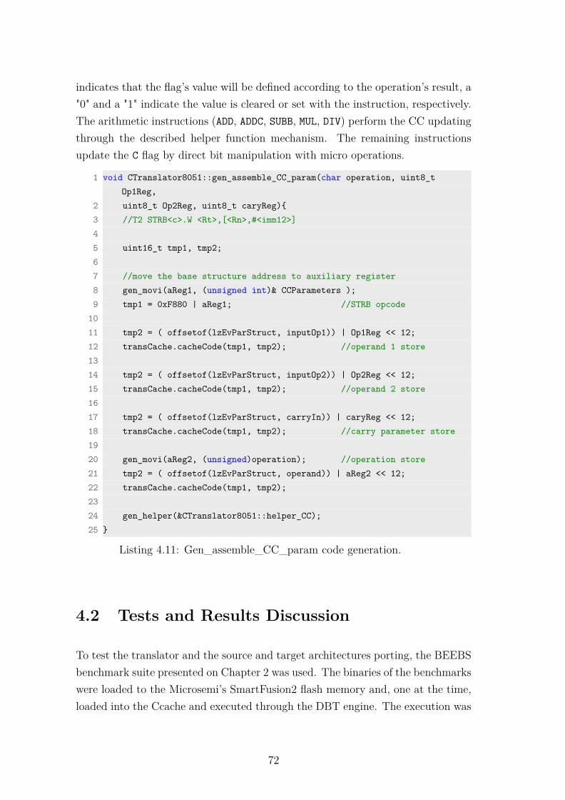
indicates that the flag’s value will be defined according to the operation’s result, a"0" and a "1" indicate the value is cleared or set with the instruction, respectively.The arithmetic instructions (ADD, ADDC, SUBB, MUL, DIV) perform the CC updatingthrough the described helper function mechanism. The remaining instructionsupdate the C flag by direct bit manipulation with micro operations.
1 void CTranslator8051::gen_assemble_CC_param(char operation, uint8_tOp1Reg,
2 uint8_t Op2Reg, uint8_t caryReg){3 //T2 STRB<c>.W <Rt>,[<Rn>,#<imm12>]45 uint16_t tmp1, tmp2;67 //move the base structure address to auxiliary register8 gen_movi(aReg1, (unsigned int)& CCParameters );9 tmp1 = 0xF880 | aReg1; //STRB opcode
1011 tmp2 = ( offsetof(lzEvParStruct, inputOp1)) | Op1Reg << 12;12 transCache.cacheCode(tmp1, tmp2); //operand 1 store1314 tmp2 = ( offsetof(lzEvParStruct, inputOp2)) | Op2Reg << 12;15 transCache.cacheCode(tmp1, tmp2); //operand 2 store1617 tmp2 = ( offsetof(lzEvParStruct, carryIn)) | caryReg << 12;18 transCache.cacheCode(tmp1, tmp2); //carry parameter store1920 gen_movi(aReg2, (unsigned)operation); //operation store21 tmp2 = ( offsetof(lzEvParStruct, operand)) | aReg2 << 12;22 transCache.cacheCode(tmp1, tmp2);2324 gen_helper(&CTranslator8051::helper_CC);25 }
Listing 4.11: Gen_assemble_CC_param code generation.
4.2 Tests and Results Discussion
To test the translator and the source and target architectures porting, the BEEBSbenchmark suite presented on Chapter 2 was used. The binaries of the benchmarkswere loaded to the Microsemi’s SmartFusion2 flash memory and, one at the time,loaded into the Ccache and executed through the DBT engine. The execution was
72
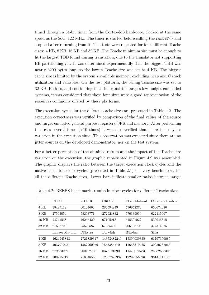
timed through a 64-bit timer from the Cortex-M3 hard-core, clocked at the samespeed as the SoC, 122 MHz. The timer is started before calling the runDBT() andstopped after returning from it. The tests were repeated for four different Tcachesizes: 4 KB, 8 KB, 16 KB and 32 KB. The Tcache minimum size must be enough tofit the largest TBB found during translation, due to the translator not supportingBB partitioning yet. It was determined experimentally that the biggest TBB wasnearly 3200 bytes long, so the lowest Tcache size was set to 4 KB. The biggestcache size is limited by the system’s available memory, excluding heap and C stackutilization and variables. On the test platform, the ceiling Tcache size was set to32 KB. Besides, and considering that the translator targets low-budget embeddedsystems, it was considered that these four sizes were a good representation of theresources commonly offered by these platforms.
The execution cycles for the different cache sizes are presented in Table 4.2. Theexecution correctness was verified by comparison of the final values of the sourceand target emulated general purpose registers, SFR and memory. After performingthe tests several times (>10 times) it was also verified that there is no cyclesvariation in the execution time. This observation was expected since there are nojitter sources on the developed demonstrator, nor on the test system.
For a better perception of the obtained results and the impact of the Tcache sizevariation on the execution, the graphic represented in Figure 4.9 was assembled.The graphic displays the ratio between the target execution clock cycles and thenative execution clock cycles (presented in Table 2.1) of every benchmarks, forall the different Tcache sizes. Lower bars indicate smaller ratios between target
Table 4.2: BEEBS benchmarks results in clock cycles for different Tcache sizes.
FDCT 2D FIR CRC32 Float Matmul Cubic root solver
4 KB 38427118 60104663 286594849 596952276 653674026
8 KB 27563054 58293771 272921832 570339030 622115667
16 KB 24741538 46255420 67105918 525301022 530945315
32 KB 21696723 25629587 67085400 206196708 474314975
Integer Matmul Dijkstra Blowfish Rjindael SHA
4 KB 1624945813 2721839347 14373482249 15890039335 61797356085
8 KB 403797045 1562260959 7553385770 11653319425 39950737066
16 KB 279683259 900492708 8375191690 11479072783 25382638325
32 KB 309275719 716048566 12367325937 17299556826 36141117175
73

0,00
5,00
10,00
15,00
20,00
25,00 4
k
8k
16
k
32
k
4k
8k
16
k
32
k
4k
8k
16
k
32
k
4k
8k
16
k
32
k
4k
8k
16
k
32
k
4k
8k
16
k
32
k
4k
8k
16
k
32
k
4k
8k
16
k
32
k
4k
8k
16
k
32
k
4k
8k
16
k
32
k
FDCT 2D FIR CRC32 Float Matmul Cubic root solver
Integer Matmul
Dijkstra Blowfish Rjindael SHA
trg/src clk cycles ratio performance threshold 1 performance threshold 2
Figure 4.9: Target/source global execution ratio, for different Tcache sizes.
and source clocks, which invoke better performance. The ratio between the targetand source execution clock cycles varies between approximately 23× (22.8, FloatMatmul, 4 KB) and 2.5× (2.37, CRC32, 16 KB and 32 KB) slower. The resultsare uplifting, considering the minimalist approach followed (deployment withoutadvanced decoding algorithms, unoptimized code generation, simplistic Tcache),the use of an IR for multiple source/target architectures bridging and the one-to-many instructions mapping. For a time based comparison, and on an speculativeexercise, since this analysis is based on educated assumptions, the Cortex-M3mainstream core line with a clock speed of 72 MHz was selected, considering themodern cortex-m3 processor’s clock speeds variation from a few dozens MHz (32MHz for the low-power families) up to a few hundred MHz (216 MHz in the pow-erful Cortex-M7). For the source clock speed, the common MCS-51 legacy coresused a 11.059 MHz clock frequency. This originates a target/source clock ratio of6.51, represented in the same figure as the "performance threshold 1". Under thesecondition, 13 out of the total 40 tests would be running faster in the translationengine than on the native platform. Going even further on the conclusion, andtaking the obtained deployment of the translator, running at 122 MHz on the Mi-crosemi’s SmartFusion2 Cortex-M3 core, the clock ratio of 11× is represented as athe "performance threshold 2" green line. Under these condition, 25× of the testsexecute in less time under the translator than under native execution, representing62.5% of the tests.
From this representation it is possible to conclude that Tcache size increase has adirect impact on the execution performance. A size increase most commonly causesa performance increase but the relation is not linear. There are even benchmarkswhere the Tcache size increase does not correlate with the performance gain. Thefundamental fact for the performance increase is that a bigger Tcache accommo-
74

dates more translated code, thus fewer translations must be evicted in order togive place to newer translations. This causes more Tcache hits and less misses,reducing the issuing of repeated translations of code that was still in use but hadto be discarded. There are tests where the Tcache variation has a sudden impacton the performance, such as the CRC32 (8 KB to 16 KB), Float Matmul (16 KBto 32 KB) and Integer Matmul (4 KB to 8 KB). This is due to occasional rela-tions between the benchmarks’ cycles size and the Tcache size, suggesting that theperformance bumps occur when the Tcache size becomes big enough to accommo-date the translations of the full source binaries, or at least an extensively executedcycle(s). This phenomena however does not explain why benchmarks such as theBlowfish, Rjindael and SHA do not consecutively reduce their execution time withthe Tcache size increase. On these three cases, the performance improvement for aTcache bigger than 4 KB, is clearly due to the size increase. However, the perfor-mance decrease, specially for the biggest Tcache size (32 KB), can not be explainedwith Tcache and TBB size relations. It was found that in these cases, what wasdeployed as a simpler and apparently effective solution, degrades the performancefor greater Tcache sizes and large binaries whose translation do not fit completelyin the Tcache. The cause is the Tcache search mechanism, deployed as a linked listand with insertion and access at the tail, for spatial locality of reference advantagepurposes. The size of the TBB also plays a role in this assertion, because thesmaller the TBBs are, the more TBBs will be accommodated in the Tcache, andthe more extensive the linked lists becomes, increasing the search time for missedTBB prior to order a new translation.
An alternative Tcache management algorithm based on a "minimal and efficient"hash table macros (uthash.h [123]) was deployed, in order to confront both im-plementations and evaluate the impact of the constant-time search approach ofthe hash table method. It should be noted that the hash approach was initiallydropped due to the expected excessive overheads associated with the hash keycomputation. Figure 4.10 add the benchmark results of the hash table managedTcache to the already presented linked list managed Tcache, from Figure 4.9. Itis now possible to compare both deployments and observe that none fully exceedsthe other. The linked list management results show better performance for smallerTcache sizes (4 KB and 8 KB), while for an intermediate 16 KB size there is noconsensus. For the greater size (32 KB) the results for the Tcache managed byhash table always overpass the linked list results. Nonetheless, hash table managedTcache tests perform consistently better with the Tcache capacity increments. The
75

0,00
5,00
10,00
15,00
20,00
25,00
30,00 lis
t
has
h
list
has
h
list
has
h
list
has
h
list
has
h
list
has
h
list
has
h
list
has
h
list
has
h
list
has
h
list
has
h
list
has
h
list
has
h
list
has
h
list
has
h
list
has
h
list
has
h
list
has
h
list
has
h
list
has
h
4k 8k 16k 32k 4k 8k 16k 32k 4k 8k 16k 32k 4k 8k 16k 32k 4k 8k 16k 32k
FDCT 2D FIR CRC32 Float Matmul Cubic root solver
l. list t/s clk ratio hash t. t/s clk ratio performance threshold 1 performance threshold 2
(a) FDCT, 2D FIR, CRC32, Float Matmul and Cubic root solver results.
0,00
5,00
10,00
15,00
20,00
25,00
30,00
list
has
h
list
has
h
list
has
h
list
has
h
list
has
h
list
has
h
list
has
h
list
has
h
list
has
h
list
has
h
list
has
h
list
has
h
list
has
h
list
has
h
list
has
h
list
has
h
list
has
h
list
has
h
list
has
h
list
has
h
4k 8k 16k 32k 4k 8k 16k 32k 4k 8k 16k 32k 4k 8k 16k 32k 4k 8k 16k 32k
Integer Matmul Dijkstra Blowfish Rjindael SHA
l. list t/s clk ratio hash t. t/s clk ratio performance threshold 1 performance threshold 2
(b) Integer Matmul, Dijkstra, Blowfish, Rjindael and SHA results.
Figure 4.10: Target/source global execution ratio, for linked list and hash tableTcache managements for different Tcache sizes.
explanation rely on the fact that while the search time for the linked list managedTcache varies with the number of TBB in the Tcache, in the hash table managedthe search time is always the same. This leads to although the hash key computa-tion overhead being considerable, it is exceeded by the search time when a largenumber of TBB are cached. This is the case for some of the 16 KB results and allof the 32 KB results, except when all the TBB fit into the Tcache.
Thus, hash tables have prejudicial impact on small Tcache sizes configurations ofthe DBT engine, because of the implied hash key algorithm computation, howeverthis cost starts to pay off for greater Tcache sizes.
This conclusion suggests the implementation of hardware assisted Tcache man-agement algorithms to improve the translated code management and access. Suchhardware mechanism should have no performance harm on any Tcache size since in-sertion and search mechanisms should be performed in parallel with the softwareand deterministically. Another suggestion regarding the Tcache management is
76
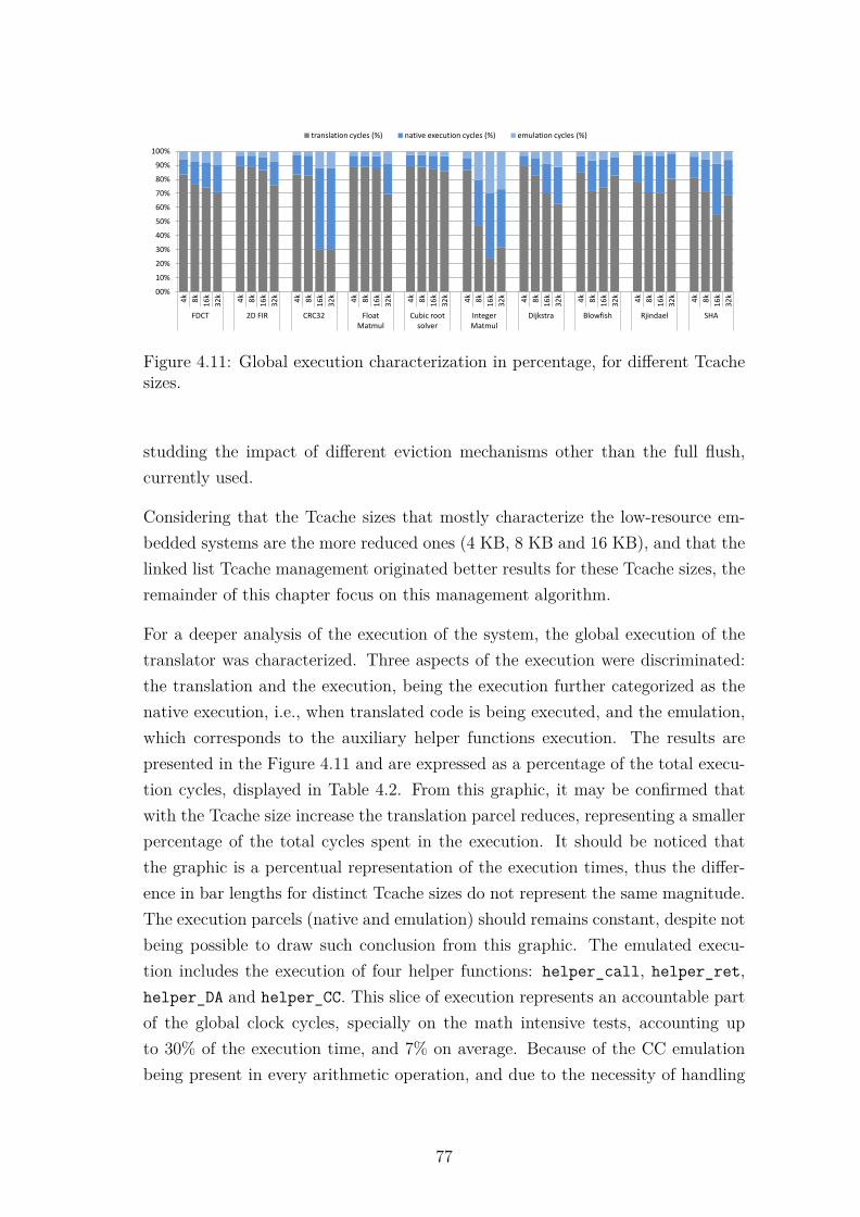
00%
10%
20%
30%
40%
50%
60%
70%
80%
90%
100%
4k
8k
16
k
32
k
4k
8k
16
k
32
k
4k
8k
16
k
32
k
4k
8k
16
k
32
k
4k
8k
16
k
32
k
4k
8k
16
k
32
k
4k
8k
16
k
32
k
4k
8k
16
k
32
k
4k
8k
16
k
32
k
4k
8k
16
k
32
k
FDCT 2D FIR CRC32 Float Matmul
Cubic root solver
Integer Matmul
Dijkstra Blowfish Rjindael SHA
translation cycles (%) native execution cycles (%) emulation cycles (%)
Figure 4.11: Global execution characterization in percentage, for different Tcachesizes.
studding the impact of different eviction mechanisms other than the full flush,currently used.
Considering that the Tcache sizes that mostly characterize the low-resource em-bedded systems are the more reduced ones (4 KB, 8 KB and 16 KB), and that thelinked list Tcache management originated better results for these Tcache sizes, theremainder of this chapter focus on this management algorithm.
For a deeper analysis of the execution of the system, the global execution of thetranslator was characterized. Three aspects of the execution were discriminated:the translation and the execution, being the execution further categorized as thenative execution, i.e., when translated code is being executed, and the emulation,which corresponds to the auxiliary helper functions execution. The results arepresented in the Figure 4.11 and are expressed as a percentage of the total execu-tion cycles, displayed in Table 4.2. From this graphic, it may be confirmed thatwith the Tcache size increase the translation parcel reduces, representing a smallerpercentage of the total cycles spent in the execution. It should be noticed thatthe graphic is a percentual representation of the execution times, thus the differ-ence in bar lengths for distinct Tcache sizes do not represent the same magnitude.The execution parcels (native and emulation) should remains constant, despite notbeing possible to draw such conclusion from this graphic. The emulated execu-tion includes the execution of four helper functions: helper_call, helper_ret,helper_DA and helper_CC. This slice of execution represents an accountable partof the global clock cycles, specially on the math intensive tests, accounting upto 30% of the execution time, and 7% on average. Because of the CC emulationbeing present in every arithmetic operation, and due to the necessity of handling
77

00%
10%
20%
30%
40%
50%
60%
70%
80%
90%
100% 4
k
8k
16
k
32
k
4k
8k
16
k
32
k
4k
8k
16
k
32
k
4k
8k
16
k
32
k
4k
8k
16
k
32
k
4k
8k
16
k
32
k
4k
8k
16
k
32
k
4k
8k
16
k
32
k
4k
8k
16
k
32
k
4k
8k
16
k
32
k
FDCT 2D FIR CRC32 Float Matmul
Cubic root solver
Integer Matmul
Dijkstra Blowfish Rjindael SHA
native execution (excl. CC) (%) emulation (excl. CC) (%) CC emulation (%) CC native execution (%)
Figure 4.12: Execution characterization in percentage, for different Tcache sizes.
it though emulation, most of the emulation time corresponds to CC emulation.
The execution cycles were further characterized and studied, taking into accountthe clock cycles spent on CC handling. Because there is also native code associatedwith helper functions calling, and specially with the CC handling helper function,which must pass the operands and operation to the CC_Parameter structure, thenative execution cycles dedicated to CC were accounted separately, as well as thecycles spent in the CC_helper function. The results are presented in Figure 4.12.The execution not involving any CC activity is represented in the two bottomcolors, on the other hand, the CC related execution (native and emulation) arerepresented by the two lighter top bars. First, it was observed that there are nochanges in the execution parcels for the different cache size tests, corroboratingthe findings extracted from Figure 4.11 analysis. This expresses that the executionis not affected by the number of translations nor by the translated code location.Second, it was also observed that the percentage of cycles dedicated to the CCcalculation is on average 26% of the execution cycles, reaching up to 45% of thecomputation cycles on arithmetic intensive benchmarks (e.g., Integer Matmul). Toglobally characterize the clock cycles cost associated with the CC handling, andbecause the translation cycles spent in such handling were unknown, the graphicdepicted in Figure 4.13 presents the total clock cycles cost associated with the CCemulation mechanism.
From this graphic it is possible to quantify the percentage of clock cycles dedicatedto the CC handling during the binaries translation. Despite only being executedonce for each CC affecting instruction, for smaller Tcache sizes, where translatedTBBs are expected to be evicted to give room for other translations, the cost ofcode generation for the CCs adds up with repeated translations. This translation
78

00%
05%
10%
15%
20%
25%
30%
35%
4k
8k
16
k
32
k
4k
8k
16
k
32
k
4k
8k
16
k
32
k
4k
8k
16
k
32
k
4k
8k
16
k
32
k
4k
8k
16
k
32
k
4k
8k
16
k
32
k
4k
8k
16
k
32
k
4k
8k
16
k
32
k
4k
8k
16
k
32
k
FDCT 2D FIR CRC32 Float Matmul Cubic root solver
Integer Matmul
Dijkstra Blowfish Rjindael SHA
CC translation cycles (%) CC emulation cycles (%) CC native cycles (%)
Figure 4.13: Total CC handling characterization in percentage, for different Tcachesizes.
cost even exceeds the execution costs of CCs handling for the smaller Tcachesizes for almost every test. The overall clock cycles dedicated to CC handling onthe system varies from 2.7% to 34.4% of the tests total time, with an average of11.5%. For the tests where was observed that the Tcache size was big enoughto accommodate the full translation of the binaries (CRC32 16 KB and 32 KB;Float Matmul 32 KB; Integer Matmul 16 KB and 32 KB), the CC translationcycles become negligible (<0.05%). According to these results the handling of theCCs could and should be addressed as a performance harmful task, deserving theapplication of techniques to attenuate such overheads. Furthermore, there is noCC handling time in the source architectures, every time dedicated to it in theDBT process is already incurring in overhead. The same assumption may be madefor every behavior emulated through helper functions, however the high frequencyfrom which the CC emulation routine is executed makes it specially critical.
4.3 Conclusions
In this chapter was presented the demonstrator of the DBT architecture previ-ously proposed. The source and target architecture porting tasks were describedand exemplified with code listings. The requirements and design decisions pro-posed in the previous chapter were fulfilled, while the implementation techniquessuccessfully ensured the separation of the DBT kernel, the source and the targetconcerns, promoting code reuse. The proposed IR successfully bridged the sourceand target instructions translation, while its employment on the DBTor grantsease of pairing for other source and target architectures porting. Despite func-
79

tionally and execution-wise correct, source and target porting is a fastidious workto be deployed manually, thus it is recommended the use of automation tools forautomatic ISA pairing for future source and target porting.
The obtained DBTor is functional and executes all the 10 benchmarks from BEEBSbenchmark suite, ensuring correct computation of the data, verified through thecomparison of the final values of the source and target emulated general purposeregisters, SFR and memory. It was also verified that there is no variation in theexecution time. Performance-wise, the presented system required more cycles toperform the computations of the source binaries, taking advantage of the modernarchitectures higher clocks, it is possible to compete with the source executiontime. Tcache size has great impact on the DBTor’ execution. Generally a biggerTcache originates better performance results. Ideally the Tcache should be bigenough to fit the translation of the complete source binaries at once, howeverthat is not possible in most of the execution cases, reason why Tcache evictionmechanisms are required. The Tcache management algorithm was also found tohave impact on the performance. A solution totally or partially based in hardwarewould greatly reduce the overhead introduced by the TBB look-up.
Both the instruction decoding and the code generation mechanisms might be im-proved, contributing to reduce the translation time overhead. The execution timemight also be improved through optimization algorithms and more efficient codegeneration methods. The use of such techniques imply overhead cycles to performthe optimization algorithms and a bigger memory footprint, with possible unpre-dictable results, since in order to become effective, the optimizations obtainedmust reduce an amount of overhead equal or greater than the overhead caused bythe application of the optimization itself.
Relatively to the CC flags, extensive analysis was performed and presented, show-ing that its emulation has a significant impact on the DBTor performance. The CCupdate activity is performed by hardware and in parallel with the code execution,thus does not figure in the native execution time of the source binaries.
Hence, several improvement directions were identified: (1) the translation process,i.e., an improved decoding mechanism for quicker source instruction to IR microoperations decomposition; (2) generated code quality, i.e., adequate the generatedcode for the target architecture, through direct register mapping, TBB chain-ing and other light weight optimization techniques; (3) Tcache management, i.e.,management mechanisms with reduced overhead; and (4) emulation mechanisms
80

efficiency, for a first pass code emulation and in CC emulation. The transla-tion process and the generated code quality might be optimized based on knownsoftware techniques migration to the embedded arena. Regarding the Tcache man-agement, it is suggested that it would greatly benefit from hardware acceleration.The topic (4) requires further investigation efforts, namely on the CC emulation,since less research is known to deal with this topic. In an attempt to improve theCC handling the next chapter will focus on optimization techniques to reduce theoverhead of such emulation.
81

82

Chapter 5
Handling the Condition Codes
In this chapter are evaluated different CC handling methods deployed on the pre-sented DBT engine. A novel technique to handle CC using COTS architecturaldebug hardware as a triggering mechanism is introduced, while assessing and com-paring it with two existent CCs evaluation methods on the resource-constrainedembedded systems arena. The proposed method is, functionality-wise, compara-ble with reconfigurable hardware modules or ISA extensions in open architectures.It is source architecture independent and also outcomes a limitation identified inone of the addressed techniques. The remainder of this chapter is organized asfollows: Section 5.1 introduces and identifies the problem, Section 5.2 presents themethods used, on Section 5.3 are presented the evaluation tests and the results arediscussed and finally, the conclusions are drawn in Section 5.4.
5.1 Introduction
Upon different source and target architectures, a DBT engine must deal with thecorrespondence of source and target ISA elements other than instructions, amongother matters. In order to replicate the exact behavior of the source binariesexecution into the target machine, the DBT engine must carefully emulate theISA elements affecting the execution flow, namely, the Condition Codes (CC) orFlags Bits. Because of the inherent differences between computer architectures,i.e., the variation of the quantity and quality of the CC and how and when they areaffected, CC emulation is a widely recognized challenge in DBT [16,37,45,99,124].The CC of the source architecture must be emulated on the target architecture
83

in order to achieve the correct execution flow of the binaries under translation.Emulation through software routines provides flexibility in the implementationand ease of porting of the DBT.
Upon emulation, the source architecture’s CC are calculated and/or updated bysoftware when their condition is affected by source instructions. Due to the over-head that these operations generate and regarding that CC are frequently updatedmultiple times before being read, optimization techniques must be used. On Har-monia [45] the authors try to reduce the overhead associated using the CC usingthree techniques: (1) eliminating CC redundant-compare code, (2) running a CCliveness analysis and consequent dead CC elimination, and (3) through ISA ex-tensions. The techniques proposed are based on the characteristics of an ARMto Intel Atom translator and can not be used on translators with flag disparity(e.g., parity and auxiliary carry flags are not common) and different architec-ture’s word lengths (e.g., 8-bit architecture’s overflow is not reproduced nativelyon an 32-bit architecture). Chao et al. [124] eliminate redundant flag computa-tions inside translation blocks and use Lazy Evaluation (LE) for inter block CCsoptimization, claiming 20% code size reduction and 40% performance gains. ALE of the CCs consists on saving the operands and the operations that affect theCCs on a run-time location upon the execution of affecting source instructions,as described in [86]. CC flags are then calculated upon request by CC-sensitiveinstructions, saving unnecessary calculations and time. However, the authors donot mention the source and target architectures used to collect the results, whichmight be too optimistic for architecture pairs with CC disparity. Digital FX! [16]also employs lazy evaluation of the CCs, but since this translator is directed to-wards x86 to Alpha architectures, it is able to use the technique very efficiently,taking advantage of how CCs are updated on x86 architecture. Yao et al. [99]approached the CCs problem through the use of reconfigurable hardware, repro-ducing the CCs structure on FPGA and ISA extensions to bridge the architecturalgaps. The implementation details are not described by the authors and since theresults of such solution are presented altogether with other hardware optimizationfeatures, the benefit or penalty of the technique is unknown. Although expected tobe efficient, this approach can not be used in Commercial-Of-The-Shelf products(COTS), because (1) the cores have closed architectures and (2) all the logic ishard-wired. Some of the results presented in the literature may have benefitedfrom the substantial computing power on the target architecture and convenientsimilarities between source to target architectures. They mostly rely on data-flow
84

analysis to reduce redundant computations, LE of the CC, ISA extensions and useof additional hardware on FPGA to accelerate the handling of CC flags. CustomISA extensions and architectural modifications are not possible to use on closedarchitectures or on the standalone COTS. Hardware extensions are an option onlywhen the deployment technology does include configurable logic such as FPGA,and in such cases the integrations must be compliant with the SoC architecture.Hence the results of the used techniques on resource-constrained COTS embeddedsystems are unknown.
It was also found a lacuna in the LE technique when CC are mapped on mem-ory data space. When CCs are kept on memory-independent hardware registers,accesses are made through dedicated instructions, thus making CC manipula-tion detectable at translation time. On the other hand, when CC are memorymapped [125, 126], it is extremely hard to foresee CC accesses during translationtime, in order to generate code capable of triggering a LE during execution. Thismeans that on a memory mapped implementation every instruction capable of af-fecting the memory is a potential CC modifier, and that CCs must be up-to-dateto any instruction that can read from the memory. Hence, it generates additionaloverhead in the detection of the instructions’ memory address. Moreover, morespecifically in the MCS-51 architecture case, the P bit is updated according withthe current value of the ACC. Since the architecture is a one-register machine, itcauses the ACC register to be intensively updated, causing additional CC emula-tion overhead, even using LE.
In this chapter it is proposed a novel solution for handling CCs on a DBTorwithout configurable hardware resources, while surpassing the LE limitations ondata space mapped CC architectures. The LE approach was complemented withthe hardware debug features available in the core to create an event-triggered lazyCC evaluation that was called Debug Monitor based LE. This new approach canbe applied to all processors that integrates the ARM CoreSight debug and tracesolution. It is believed that the use of hardware debug features in this manner is apioneer approach, and since it uses hard-wired on-chip logic there is no hardwareoverhead. Hence, the contributions of this chapter to the state of art are: (1)an evaluation of four different CC handling methods on the resource-constrainedembedded systems arena, (2) a novel technique to handle CC flags using COTSarchitectural debug hardware, by using (3) a triggering mechanism comparablewith reconfigurable hardware modules or ISA extensions in open architecturesand without hardware overhead; (3) heading also to solve the LE limitations on
85
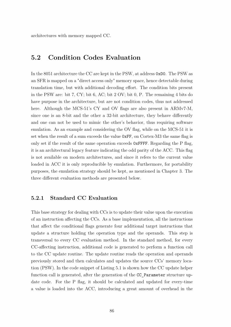
architectures with memory mapped CC.
5.2 Condition Codes Evaluation
In the 8051 architecture the CC are kept in the PSW, at address 0xD0. The PSW asan SFR is mapped on a "direct access only" memory space, hence detectable duringtranslation time, but with additional decoding effort. The condition bits presentin the PSW are: bit 7, CY; bit 6, AC; bit 2 OV; bit 0, P. The remaining 4 bits dohave purpose in the architecture, but are not condition codes, thus not addressedhere. Although the MCS-51’s CY and OV flags are also present in ARMv7-M,since one is an 8-bit and the other a 32-bit architecture, they behave differentlyand one can not be used to mimic the other’s behavior, thus requiring softwareemulation. As an example and considering the OV flag, while on the MCS-51 it isset when the result of a sum exceeds the value 0xFF, on Cortex-M3 the same flag isonly set if the result of the same operation exceeds 0xFFFF. Regarding the P flag,it is an architectural legacy feature indicating the odd parity of the ACC. This flagis not available on modern architectures, and since it refers to the current valueloaded in ACC it is only reproducible by emulation. Furthermore, for portabilitypurposes, the emulation strategy should be kept, as mentioned in Chapter 3. Thethree different evaluation methods are presented below.
5.2.1 Standard CC Evaluation
This base strategy for dealing with CCs is to update their value upon the executionof an instruction affecting the CCs. As a base implementation, all the instructionsthat affect the conditional flags generate four additional target instructions thatupdate a structure holding the operation type and the operands. This step istransversal to every CC evaluation method. In the standard method, for everyCC-affecting instruction, additional code is generated to perform a function callto the CC update routine. The update routine reads the operation and operandspreviously stored and then calculates and updates the source CCs’ memory loca-tion (PSW). In the code snippet of Listing 5.1 is shown how the CC update helperfunction call is generated, after the generation of the CC_Parameter structure up-date code. For the P flag, it should be calculated and updated for every-timea value is loaded into the ACC, introducing a great amount of overhead in the
86
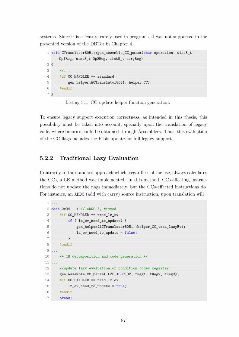
systems. Since it is a feature rarely used in programs, it was not supported in thepresented version of the DBTor in Chapter 4.
1 void CTranslator8051::gen_assemble_CC_param(char operation, uint8_tOp1Reg, uint8_t Op2Reg, uint8_t caryReg)
2 {3 //...4 #if CC_HANDLER == standard5 gen_helper(&CTranslator8051::helper_CC);6 #endif7 }
Listing 5.1: CC update helper function generation.
To ensure legacy support execution correctness, as intended in this thesis, thispossibility must be taken into account, specially upon the translation of legacycode, where binaries could be obtained through Assemblers. Thus, this evaluationof the CC flags includes the P bit update for full legacy support.
5.2.2 Traditional Lazy Evaluation
Contrarily to the standard approach which, regardless of the use, always calculatesthe CCs, a LE method was implemented. In this method, CCs-affecting instruc-tions do not update the flags immediately, but the CCs-affected instructions do.For instance, an ADDC (add with carry) source instruction, upon translation will
1 ...2 case 0x34 : // ADDC A, #immed3 #if CC_HANDLER == trad_lz_ev4 if ( lz_ev_need_to_update) {5 gen_helper(&CTranslator8051::helper_CC_trad_lazyEv);6 lz_ev_need_to_update = false;7 }8 #endif9 ...
10 /* IR decomposition and code generation */11 ...12 //update lazy evaluation of condition codes register13 gen_assemble_CC_param( LZE_ADDC_OP, tReg1, tReg2, tReg3);14 #if CC_HANDLER == trad_lz_ev15 lz_ev_need_to_update = true;16 #endif17 break;
87

18 ...
Listing 5.2: Lazy evaluation CC handling example code snippet.
have to generate code to perform the necessary function call to update the CCs,so that later the CY and the other flag bits can be read and used with coherency.The P flag will also be updated, together with the other CCs. A dataflow analysisis performed during translation, to reduce CC flags update calls, as in [124] andtherefore unnecessary overhead. This dynamic analysis is kept to a minimal levelfor overhead containment reasons. A flag called lz_ev_need_to_update is settrue after every instruction that affects the CC (through LE), meaning that theCC must be updated before being read next time. The instructions that readthe CC (e.g., ADDC) will only generate code to update the CC in case the lz_ev_-need_to_update flag is set true, otherwise (i.e., when false) the CC update codegeneration can be skipped, because the CC are up to date. In the code snippetbellow, the ADDC instruction is shown as an example of an instruction that both"affects" and "is affected" by the CC, when using the Traditional Lazy Evaluation.The full legacy support cost for this type of evaluation is additional CC evaluationhelper function calls, since each instruction that affects the ACC will also set thelz_ev_need_to_update flag.
5.2.3 CC Lazy Evaluation Integrated with Debug Features
The limitations of the state of the art regarding CC mapped on memory dataspace, identified in the Section 3.1, are related with the possibility of every memoryaccess instruction accessing and modifying the PSW, the address of the CC flags.This requires an enhanced decoding of the memory access instructions in order toidentify the target memory address of the instruction, and perform the necessaryoperations if the address is 0xD0, the PSW address.
To avoid the recurrent updates of the CC (and the associated performance penalty)and the additional decoding overhead of a LE approach it is proposed the idea ofemploying the debug capabilities of the Cortex-M3 to perform the detection ofmemory accesses to the PSW address. Since this hardware is included in the coreand runs with total independence and parallelism from the core, its integrationwould provide the extra logic in need without extra hardware costs.
The CoreSight architecture support two debug modes: (1) a halting debug mode
88

where core execution is halted for probing and (2) the debug monitor mode, whichtriggers a debug exception handler routine to perform the necessary debug op-erations. In accordance, a possible use of the debug monitor mode is to watchfor memory accesses (read, write or both) and trigger a debug monitor exceptionon those addresses under surveillance. Since CoreSight is the industry standardfor debug and trace by ARM, available not only on ARM products but also asintellectual property (IP) for third party, this presented method is portable to allCoreSight compliant COTS.
This mechanism was applied to monitor the memory accesses and trigger an excep-tion that updates the CC flags upon read accesses of the PSW emulated memorylocation. One of the comparators of the DWT module present in the target ARMCortex-M3 was programmed to watch the memory read accesses on the sourcememory address 0xD0. Then, from the debug monitor handler the CC updateroutine is called to calculate and update the value of the CC flags. The flagswill be computed based on the LE information stored by the last CCs-affectinginstruction. By doing so, when there is a pending update and CCs are required byan instruction, an exception is triggered and the flags’ values are calculated priorto use, ensuring a correct emulation. The DWT comparator is configured to watchonly read accesses since on write accesses the previous CCs will be overwritten.A dataflow analysis strategy is still performed in this method, by enabling anddisabling the Debug Monitor exception in the same way as the lz_ev_need_to_-update flag previously described. The code snippet bellow shows the code usedto enable and disable the DWT and configuring the type of access trigger form.
1 #if (CC_HANDLER == debug_mon )2 //MON_CMD values3 #define MON_RO 0x054 #define MON_WO 0x065 #define MON_OFF 0x0067 //macro to turn the debug monitor ON or OFF8 #define set_debug_mon_CMP0( MON_CMD ) (DWT->FUNCTION0 = MON_CMD)9 #endif
Listing 5.3: Debug monitor DWT comparator control code snippet.
89

5.3 System Evaluation
The evaluation of the different approaches, Standard CC Evaluation, TraditionalLazy Evaluation and Debug Monitor based Lazy Evaluation, was carried throughthe execution of the BEEBS benchmarks for the four different Tcache sizes, 4 KB,8 KB, 16 KB and 32 KB. The tests were performed for the linked list managedTcache due to the better results that this management algorithm offers for smallerTcache sizes and also because the smaller Tcache sizes will be the most commoncase in the resource-constrained embedded systems. The benchmark results areshown in the Graphics 5.1a and 5.1b in Figure 5.1, together with the performancethreshold lines one and two, for reference.
The results display that, globally, a full legacy support, in detriment of an approx-
0,00
5,00
10,00
15,00
20,00
25,00
30,00
stan
dar
d
trad
_lz
deb
ug_
mo
n
stan
dar
d
trad
_lz
deb
ug_
mo
n
stan
dar
d
trad
_lz
deb
ug_
mo
n
stan
dar
d
trad
_lz
deb
ug_
mo
n
stan
dar
d
trad
_lz
deb
ug_
mo
n
stan
dar
d
trad
_lz
deb
ug_
mo
n
stan
dar
d
trad
_lz
deb
ug_
mo
n
stan
dar
d
trad
_lz
deb
ug_
mo
n
stan
dar
d
trad
_lz
deb
ug_
mo
n
stan
dar
d
trad
_lz
deb
ug_
mo
n
stan
dar
d
trad
_lz
deb
ug_
mo
n
stan
dar
d
trad
_lz
deb
ug_
mo
n
stan
dar
d
trad
_lz
deb
ug_
mo
n
stan
dar
d
trad
_lz
deb
ug_
mo
n
stan
dar
d
trad
_lz
deb
ug_
mo
n
stan
dar
d
trad
_lz
deb
ug_
mo
n
stan
dar
d
trad
_lz
deb
ug_
mo
n
stan
dar
d
trad
_lz
deb
ug_
mo
n
stan
dar
d
trad
_lz
deb
ug_
mo
n
stan
dar
d
trad
_lz
deb
ug_
mo
n
4k 8k 16k 32k 4k 8k 16k 32k 4k 8k 16k 32k 4k 8k 16k 32k 4k 8k 16k 32k
FDCT 2D FIR CRC32 Float Matmul Cubic root solver
standard lazy_ev debug_mon performance threshold 1 performance threshold 2
(a) FDCT, 2D FIR, CRC32, Float Matmul and Cubic root solver results.
0,00
5,00
10,00
15,00
20,00
25,00
30,00
stan
dar
d
trad
_lz
deb
ug_
mo
n
stan
dar
d
trad
_lz
deb
ug_
mo
n
stan
dar
d
trad
_lz
deb
ug_
mo
n
stan
dar
d
trad
_lz
deb
ug_
mo
n
stan
dar
d
trad
_lz
deb
ug_
mo
n
stan
dar
d
trad
_lz
deb
ug_
mo
n
stan
dar
d
trad
_lz
deb
ug_
mo
n
stan
dar
d
trad
_lz
deb
ug_
mo
n
stan
dar
d
trad
_lz
deb
ug_
mo
n
stan
dar
d
trad
_lz
deb
ug_
mo
n
stan
dar
d
trad
_lz
deb
ug_
mo
n
stan
dar
d
trad
_lz
deb
ug_
mo
n
stan
dar
d
trad
_lz
deb
ug_
mo
n
stan
dar
d
trad
_lz
deb
ug_
mo
n
stan
dar
d
trad
_lz
deb
ug_
mo
n
stan
dar
d
trad
_lz
deb
ug_
mo
n
stan
dar
d
trad
_lz
deb
ug_
mo
n
stan
dar
d
trad
_lz
deb
ug_
mo
n
stan
dar
d
trad
_lz
deb
ug_
mo
n
stan
dar
d
trad
_lz
deb
ug_
mo
n
4k 8k 16k 32k 4k 8k 16k 32k 4k 8k 16k 32k 4k 8k 16k 32k 4k 8k 16k 32k
Integer Matmul Dijkstra Blowfish Rjindael SHA
standard lazy_ev debug_mon performance threshold 1 performance threshold 2
(b) Integer Matmul, Dijkstra, Blowfish, Rjindael and SHA results.
Figure 5.1: Target/source global execution ratio, for the standard, lazy evaluationand debug monitor CC evaluation, using the linked list Tcache management, fordifferent Tcache sizes.
90

imated computing approach of the CC flags, results in greater overhead. Howeverthe CC optimization techniques allow a reduction of that overhead to values closeto the obtained with approximated computing in the previous chapter (Figure4.9). In the experiments, traditional LE is consistently better than the standardmethod and the proposed novel method is also better than the traditional LE.
The Traditional Lazy Evaluation achieved a global overhead reduction of 24%on average. The greatest performance achievement was for the 16 KB Tcachesize, with an average reduction of 28%, having the individual bechmark Dijkstraachieved a reduction of 51%. The novel debug monitor based approach achievedeven better performance, contributing to a global average clock cycles reductionof 29.8%. The obtained average performance improvements per Tcache sizes are26.5%, 31.2%, 34.3% and 27.3%, for the 4 KB, 8 KB, 16 KB and 32 KB, respec-tively. The variation on the results of the greatest Tcache sizes for the benchamrksin the Graphic 5.1b is explained due the performance penalty induced by the linkedlist management of the Tcache. Namely, in the case of the 32 KB Tcache SHAbenchmark, it is noticeable a considerable performance penalty of the debug mon-itor methods over the lazy evaluation method. This is due to the debug monitormethods producing fewer target code (the CC handling routine calls are triggered,not embedded in the generated code), thus resulting in smaller BBs and causing abigger number of BBs to fit in the Tcache. This sound consequence induces greatersearch time penalty in the linked list managed Tcache, thus the bad result of thebenchmark.
There are also some variations in the amount of performance improvement, overthe two optimized evaluation methods. Despite both methods implementing alazy evaluation approach for the CC evaluation, they rely on different implemen-tations and generate different types of overheads, thus originating distinct results.In other words, the debug monitor methods is capable of eliminating some of theextra decoding overhead through the migration of the CC update triggering func-tionalities to the CoreSight hardware, however it introduces the exception latencyof the debug monitor exception. Hence, the variation of the benchmarks’ size, thenumber of their intrinsic loops and its iterations have different impacts on the twolazy evaluation approaches.
The functional advantage of the Debug Monitor based Lazy Evaluation methodfor the problem of CC mapped in memory data space, approached on Section5.1 is visible though the performance improvements of the benchmarks. Thus if
91

the CC of the source architecture are mapped into the data space [125, 126], theLazy Evaluation Integrated with Debug Features reveals a valid contribution andshould be used. This approach ensuring that the CC flags are only calculatedwhen necessary, but are always up-to-date when accessed.
5.4 Conclusion
In this chapter, three different CC handling mechanisms in DBT specialized forembedded systems were assessed based on results obtained from actual implemen-tations: (1) the standard evaluation of the CC upon the execution of CC-affectinginstruction; (2) a traditional lazy evaluation of the CC; (3) a novel lazy evaluationbased on the features of the CoreSight debug monitor hardware. The proposednew method proved to be functional and offered performance gains over the othertwo evaluated methods. Specifically, nearly 30% over the standard evaluation and6% over the traditional lazy evaluation, on average.
The use of the debug monitor in the DBT architecture provides a triggering mech-anism only comparable with the use of reconfigurable hardware modules in thearchitecture, but using only COTS features. Due to the CoreSight popularity thisis a highly portable method. Its multipurpose and functionalities are appealingfor peripherals mapping and exception emulation exploration also. The use ofthe debug features as a software triggering mechanism might be also applied inother type of applications than DBT, whenever a certain action is required upondynamic and unpredictable behavior, e.g., code instrumentation, virtualization.
Regarding the CC evaluation optimization and acceleration, the results encouragehardware based approaches for overhead mitigation. This need is justified with thelack of parallelism that all the approaches failed to provide in the CC evaluation.Natively CC are updated with total parallelism from the program computations,but when DBT is applied, the CC emulation will compete against the sourceprogram computations for the processing resources, unquestionably resulting inoverhead. However, in order to be COTS compliant, the hardware integrationmust come in a non-intrusive manner (i.e., without architectural modifications orISA extensions), so that it can be considered as an acceleration solution for thelow-cost/resource-constrained embedded systems.
92

Chapter 6
Non-intrusive Hardware-AssistedAcceleration
In the previous chapters an approach to DBT on resource-constrained embed-ded systems has been explored and evaluated, leading to several acceleration andimprovement suggestions that rely on dedicated hardware. Software to hardwareoffloading is a common acceleration procedure used when software-only approachesdo not meet the performance requirements. There are however other motivationsto embark on software to hardware tasks migration, namely, functionality exten-sions and shortfalls overcome.
This chapter approaches hardware offloading to address the previously identifiedlimitations of the DBT engine regarding the Tcache management and the CCsevaluation methods. The suggested approaches remain non-intrusive to the tar-get architecture, which cope with the COTS-driven deployment of DBT for theresource-constrained embedded devices. It is proposed a Tcache management mod-ule and a non-intrusive hybrid acceleration architecture that extends the function-alities of the DBT engine to support peripherals remapping and to deal with fullydynamic behaviors, such as interrupt handling.
The remaining of the chapter is organized as follows: Section 6.1 presents a com-prehensive introduction and the related work; Section 6.2 introduces and evaluatesa hardware Tcache management mechanism. Section 6.3 proposes a non-intrusiveacceleration architecture, while the remaining sections 6.4, 6.5 and 6.6, use thehardware based acceleration architecture to evaluate another CC handling mech-anism, peripherals support and remapping, and interrupt handling, respectively.
93

Section 6.7 contains the conclusions drawn during the chapter.
6.1 Introduction
Based on evidences gathered through previous chapters, some features of the im-plemented DBT engine would probably benefit from hardware acceleration. It isknown that software to hardware task migration is a performance enhancementtechnique widely used in many fields and applications, when software-only ap-proaches do not deliver the necessary metrics; and DBT is not an exception.
In [127], Borin et al. presented a strategy to identify the main sources of overheadinvolved in the process of DBT. Despite the study concerning DBT aimed at desk-top processors, thus, not applied directly to embedded systems, evaluation param-eters such as cold code translation and translated code execution are transversal tothe DBT topic. Among other suggestions, the authors point that research in over-head reduction through hardware support should be conducted in order to achievenear zero overhead DBT. Yao et al. [99] identified that common DBT systemssuffer performance loss because of architectural heterogeneity among ISAs, con-trol flow and context switches. In the same work, it is proposed an FPGA-basedhardware/software co-designed acceleration solution, achieved through (1) registerreplication in reconfigurable hardware and (2) ISA extensions. The authors claima global speed-up of 56.1%, but provide very shallow details on the integrationof techniques and DBT engine characteristics. Despite apparently efficient, theapproach comes with the cost of architectural modifications to the target proces-sor. Gomes et al. [128, 129] have used hardware to deploy functionalities to solveproblems found in real-time operating system (RTOS) state of the art. Throughhardware assistance, the authors managed to unify the priority space in interrupthandling and also deployed a mixed hardware/software multi-thread scheduler forRTOS, increasing its predictability. The hardware extensions were integrated inthe core in a tightly-coupled fashion, requiring access to the core architecture. Thisis considered a non COTS friendly approach of hardware integration, thus does notcomply with the constrains of this work. In [130], graphics processing unit (GPU)integration in a translation framework is suggested as a form of exploring data-level and task-level acceleration opportunities from CUDA C compiled programs inAMD’s runtime environment for GPUs. Although a heterogeneous solution wouldbe viable in the deployed DBTor, the described work applies only for platforms
94
where a GPU is present, i.e., a high-performance system, which is not target ofthis thesis. DBTIM is a hardware assisted architecture-DBT for full virtualiza-tion [30]. The solution targets high-performance systems and uses a reconfigurableDBT chip, deployed in a DIMM, coupled into a motherboard in order to providefull hardware virtualization of the host CPU. The DBT chip receives the sourcecode and the translation request through the memory interface, processes the re-quest and delivers the translated code through the same mechanism. The approachis an example of hardware integration over traditional systems, without requiringarchitectural modifications to the target architecture. The use of FPGA fabric topromote binary compatibility is advocated in [131] and in [93]. The former pro-poses the use of hardware to promote binary compatibility, using reconfigurablecoarse grained units to execute legacy functionalities through Dynamic Instruc-tion Merging technique, a form of BT in hardware. In [93] the authors attemptto understand the challenges of applying reconfigurable computing to acceleratedynamic binary translation during runtime, using co-processors. The method isbased in the detection of execution patterns in the source code upon its profilingand subsequent loading of accelerator modules bitstream to the FPGA.
In Chapter 4, Tcache management was pointed as a functionality that would ben-efit from hardware acceleration to solve the drawbacks found in both of the at-tempted management implementations. While the linked list management approachis associated with a lower search algorithm overhead than the hash table approach,with the increase of the list nodes, the search time exceeds the hash key computa-tion time and the hash table mechanism performs better. In order to overcome thesoftware-based approaches, the hardware assisted mechanism should ensure that(1) the insertion and search time of a TBB is reduced and that (2) the search timeremains constant regardless of the number of TBB stored in the Tcache. Tcachemanagement in DBT has already been approached in the literature. Baiocchi etal. in [61] use SPM as a auxiliary memory for quick context switch between thetranslation and execution environments; by reducing the translated code and bydelegating code caching operations in the SPM. However, in this thesis’ approach,the context switch is extremely reduced (one instruction to save the return ad-dress and another to move the data memory base address). Furthermore, SPM,or Tightly Coupled Memory (TCM), is not commonly present in the resource-constrained low-budget embedded devices. In [132] the authors resort to hardwaretechniques in order to manage the code cache either in DBT or dynamic optimiz-ers. Hazelwood et al. [133] identify and study the Tcache performance on DBT,
95

presenting a framework to access and manipulate the translation cache of the PINbinary instrumentation system. Chen et al. developed extensive work in thistopic [31,33,69,94], suggesting hardware to assist a specialized instruction decodecache, the DICache. Despite the work presenting substantial improvements oversoftware-only deployments, it proposes the integration of hardware extensions atarchitectural level into an IP ARM processor core. Following Baiocchi, Yao etal. [99] also integrate SPM in FPGA to reduce context switching overheads. Fur-thermore, they present a hardware deployment of the mechanism proposed in [132],as a simple look-up table composed by a content-addressable memory (CAM) anda RAM. This mechanism seems to fit to the application scenario proposed in thisthesis, but it still uses a software hash table as a secondary mechanism to decideif the TBB is cached or not.
In Chapter 5, acceleration approaches using hardware were attempted. However,considering the non-reconfigurable COTS devices targeted, the usable hardwarewas static and set available by the manufacturer, with a predefined functionality(not for acceleration purposes) that was exploited for the purpose of DBT enhance-ment. This initial approach using the debug monitor features of the CoreSightarchitecture has revealed neat, minimalistic and cheap to implement, because (1)it is compatible with fully dynamic behavior of the execution (contrarily to trans-lation time approaches); (2) is lazy evaluation implementation friendly, once thenecessary actions are only taken upon a read or write request (avoiding unneces-sary updates); (3) introduces just small modifications to the DBT execution flow;(4) does not need a strong emulation environment; and (5) may be deployed on awide range of COTS ARM processors. However, this implementation suffers fromsome drawbacks: (1) it does not co-exist with debug functionalities; (2) it is limitedto the number of DWT comparators available in the device (commonly four); and(3) it requires the manipulation of the stack in order to modify the debug monitorinterrupt service routine (ISR) return address to repeat the instruction that causedthe interrupt. Again, Yao et al. [99] propose hardware assisted CC evaluation, butusing flags register replication on FPGA. However the authors fail into provide in-formation on how the CCs in hardware eliminates the CCs computations overheadthrough the native ALU related instructions.
The mechanism’s potential for peripherals support was also suggested in the lastchapter. Peripherals are undeniably important features of microprocessors thatnot only establish an interface between the microprocessor and the outside worldbut also enable the system to perform tasks in parallel with the processor’s compu-
96

tations. Any legacy binary code will inevitably include access to at least a few pe-ripherals (e.g., IO ports, UART, I2C, SPI, timers, analog-to-digital and vice-versaconverters), thus becoming mandatory their support by the DBTor. Despite theproposed approaches, peripherals access is still identified as a bottleneck feature inDBT. In [95] the authors identify the peripherals as one of the main componentsof an embedded system. It is also discussed that static peripherals address detec-tion, or even during translation time, is not straightforward to perform. Instead ofgoings through a table with peripherals location addresses during the decoding ofload and store instructions, the authors use hardware support for address transla-tion and look-up overhead reduction. Then, each access is catched by a peripheralsimulator in order to replicate the peripheral actions.
Another mandatory feature that should be considered is the interrupt support.Interrupts are employed in many activities in embedded systems programing, suchas inputs registration (I/O and capture mode interrupts), time event assignment(timer interrupts) or to notify the end of a task (serial ports interrupts). Regard-less of the trigger source, the handling of the different interrupts relies on the samemechanism and remains fairly consistent between different architectures. After aninterrupt being triggered, it is registered and, after priorities and other similarconsiderations, code execution is suspended and the designated handling routineis set to execute and attend the pending requested. The main aspect that differ-entiates an interrupt handling from regular and sequential code execution is thatinterrupts are unpredictable in time. This dynamic behavior introduces severedifficulties in the emulation process. The state of the art use periodic verificationto emulate the source environment and detect pending interrupts. In QEMU [86],for performance purposes, interrupts are not checked at every TBB execution. In-stead, a user call function verifies if pending interrupts must be evoked and then,interrupts are handled in the main loop of the DBT. Kondoh et al. [95] also followa similar approach, using the peripherals simulators after detecting the interruptrequest. In [128], Gomes et al. use hardware to solve an interrupt priority spaceproblem in RTOS in a way defined by authors as "minimally intrusive at hardwarearchitecture level". Nevertheless, their approach still relies on modules tightly-coupled to the processor’s micro-architecture, which is not possible to perform inclosed architectures.
To surpass the limitations identified over this section and to provide functional-ity enhancement, along with COTS products utilization, reconfigurable hardwaremust be serviced and integrated in the design. This precondition implies the use
97
of FPGA fabric to host the acceleration support system as well as the eventualacceleration modules. As foreseen in Chapter 2, the modern SoC solutions whichintegrate a hard-core processor and reconfigurable FPGA in the same device pro-vide an excellent deployment environment. Although reconfigurable, the devicestill complies with the COTS requirement of this work, hence the integration ofsuch accelerators must follow the available standard interfaces, leaving processor’smicro-architecture unaltered. The development and integration of hardware accel-erators should be sustained by an architecture that promotes flexible and scalableacceleration while minimizing the NRE efforts of individual accelerators integra-tion.
This chapter presents a hardware based mechanisms to accelerate and extend thefunctionalities of DBT applied to the resource-constrained embedded devices. Themechanisms must be compliant with COTS deployments, thus an architecturallynon-intrusive approach is desired. While the Tcache management is a DBTor-specific acceleration feature (source and target architecturally independent), theremaining accelerations possibilities suggested are dependent from the source ar-chitecture and its features to be emulated, thus the hardware acceleration shouldbe deployed in a scalable and flexible way. Based on the limitations found duringthe CC acceleration through the debug monitor hardware features, the followingcharacteristics were identified:
1. Flexibility - the same method should be applicable to multiple scenarios, e.g.,CC handling, peripherals emulation, interrupt support, etc. This requires thesolution to not be focused only on the feature to be supported, but ratheron the interaction mechanisms involved.
2. Scalability - the method should be able to efficiently deal with multiple ac-celerators/extensions in the design.
3. Non-intrusiveness - to cope with COTS products the solution must not re-quire architectural modifications at the processor level; and for ease of in-tegration in the system the accelerators should not interfere with the DBTexecution flow.
In the next sections non-intrusive hardware based solutions to address the issuesdescribed in this introduction will be presented and discussed.
98

6.2 Tcache Acceleration Assisted by Hardware
On an effort to speed up the translated code management (i.e., adding and search-ing translation entries) and obtaining a scalable management method, the Tcachemanagement effort is delegated to hardware through an FPGA deployed solution.The approach followed in [99] is well suited to be applied because it is non-intrusiveand takes full benefit of the hardware, but it still relies on a heavy software backupmechanism to handle missing translation from the hardware management. Thesoftware hash table mechanism should be avoided in the resource-constrained em-bedded systems, because of the already identified latencies it originates.
A full hardware Tcache approach was considered, but issues were faced regardingits implementation. A full hardware cache is a straight-forward implementation,either following a fully-associative, direct-mapped or set-associative policy [134].However a Tcache does not exactly resembles a cache, but rather a buffer. Whilea typical cache stores a determined memory position, which the size is known andequal to every entry, a Tcache does not contain the equivalent representation ofthe source code at every address. Each translation is only addressable by its entryaddress and its size is variable and unknown upon its creation. Dealing with suchtraits in hardware would involve a complicated mechanism to manage the availablespace, and would probably result in small improvements, since most of the Tcacheassociated overhead is related with the management rather than the data cachingand accesses.
6.2.1 Proposed Solution
An approach similar to Yao et al. was followed, however with some adjustment toavoid the use of software hash tables. The TBB caching, the eviction policy andthe available space management are processed in the same manner as before (i.e.,using a software approach), while adding new TBB entries and searching for aTBB are processed by auxiliary hardware. The hardware implementation is basedon the regular Tcache memory space allocated on the target data memory plus alook-up table, similar to a fully associative cache (CAM) + RAM) on a integratedimplementation, as depicted in Figure 6.1.
In this approach, and diverting from the one presented in [99], the output ofthe CAM is not returned to the microprocessor. In case of a source address hit,
99

Tcache hardware manager
Circular index logic
Source address query
Source address new
Target address new
Output target addressTarget Address
(RAM)
SourceAddress(CAM)
Figure 6.1: Tcache hardware manager diagram.
the target address is directly forwarded to the microprocessor. If an address missoccurs, then the address 0x00000000 is returned, indicating that the source addressis not yet translated. This NULL address may be used in case of a miss becausethe Tcache memory is never allocated at the bottom of the source data memory.There is one additional valid bit in the architecture to prevent false hits duringthe first accesses and after Tcache resets. Although the number of TBBs thatfit into the Tcache memory space varies, the number of the hardware look-up-table entries is fixed. To deal with this, other approaches include a software hashtable to index additional TBBs after the hardware look-up-table being full. Thisinduces the penalty of calculating a hash key and searching the hash table everytime a Tcache miss occurs, even when the Tcache is not full. The implementedapproach avoids the use of the software hash table through an adjustment tothe new entry insertion mechanism. It is implemented resembling a circular list.The new entries are inserted sequentially until the insertion index overflows andstarts to overwrite the first entries. The eventual look-ups of overwritten entrieswill generate a false miss because the translation is indeed stored at the Tcacheallocated memory, but its look-up position was given to another TBBs, in favorof using the remaining Tcache allocated memory before requiring a full eviction.Moreover, older entries are less likely to be required. The hardware look-up-tablesize is modifiable through a parameter and should adequate to the Tcache size,which translates into the typical number of TBB per Tcache filling. From the tenbenchmarks used it was empirically determined the following correspondence:
100
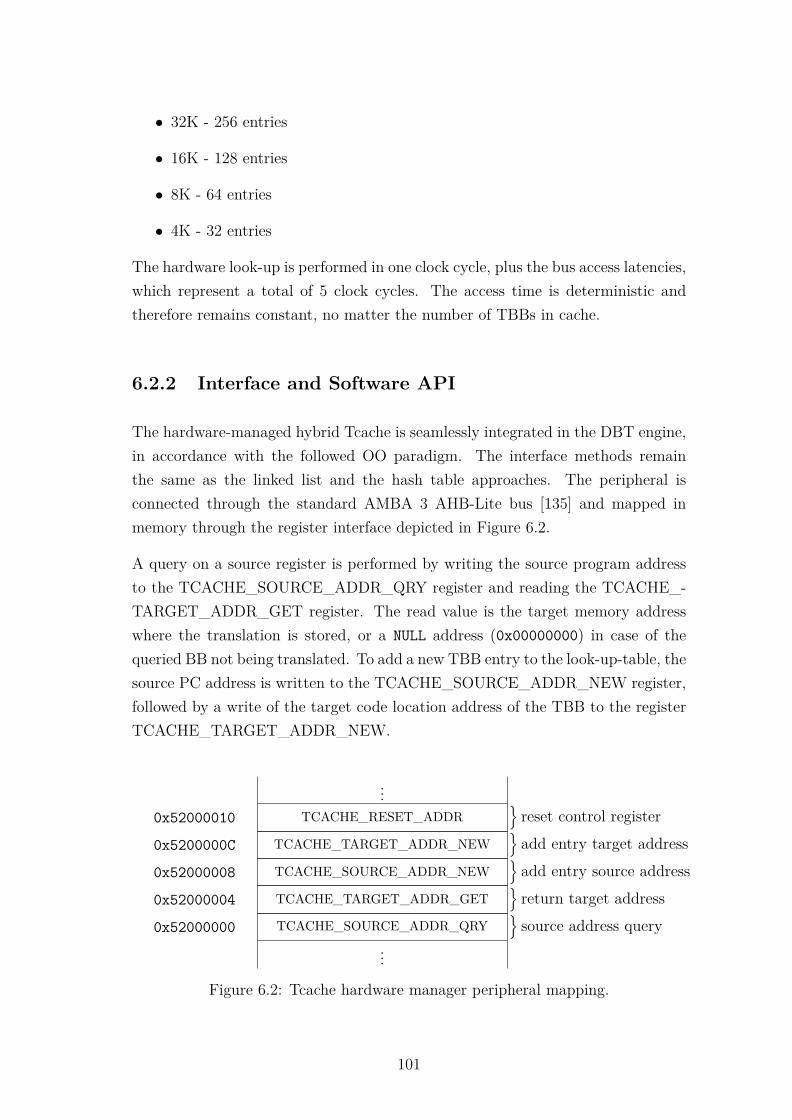
• 32K - 256 entries
• 16K - 128 entries
• 8K - 64 entries
• 4K - 32 entries
The hardware look-up is performed in one clock cycle, plus the bus access latencies,which represent a total of 5 clock cycles. The access time is deterministic andtherefore remains constant, no matter the number of TBBs in cache.
6.2.2 Interface and Software API
The hardware-managed hybrid Tcache is seamlessly integrated in the DBT engine,in accordance with the followed OO paradigm. The interface methods remainthe same as the linked list and the hash table approaches. The peripheral isconnected through the standard AMBA 3 AHB-Lite bus [135] and mapped inmemory through the register interface depicted in Figure 6.2.
A query on a source register is performed by writing the source program addressto the TCACHE_SOURCE_ADDR_QRY register and reading the TCACHE_-TARGET_ADDR_GET register. The read value is the target memory addresswhere the translation is stored, or a NULL address (0x00000000) in case of thequeried BB not being translated. To add a new TBB entry to the look-up-table, thesource PC address is written to the TCACHE_SOURCE_ADDR_NEW register,followed by a write of the target code location address of the TBB to the registerTCACHE_TARGET_ADDR_NEW.
...0x52000010 TCACHE_RESET_ADDR
}reset control register
0x5200000C TCACHE_TARGET_ADDR_NEW}add entry target address
0x52000008 TCACHE_SOURCE_ADDR_NEW}add entry source address
0x52000004 TCACHE_TARGET_ADDR_GET}return target address
0x52000000 TCACHE_SOURCE_ADDR_QRY}source address query
...
Figure 6.2: Tcache hardware manager peripheral mapping.
101
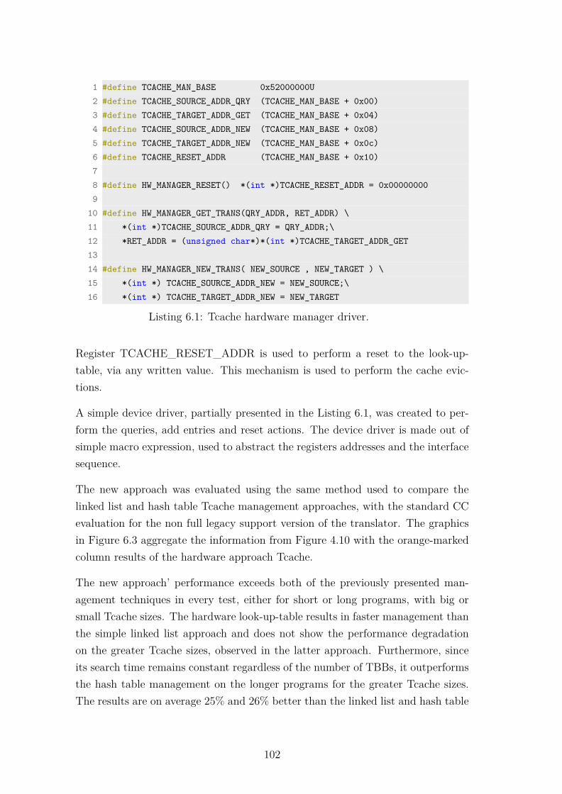
1 #define TCACHE_MAN_BASE 0x52000000U2 #define TCACHE_SOURCE_ADDR_QRY (TCACHE_MAN_BASE + 0x00)3 #define TCACHE_TARGET_ADDR_GET (TCACHE_MAN_BASE + 0x04)4 #define TCACHE_SOURCE_ADDR_NEW (TCACHE_MAN_BASE + 0x08)5 #define TCACHE_TARGET_ADDR_NEW (TCACHE_MAN_BASE + 0x0c)6 #define TCACHE_RESET_ADDR (TCACHE_MAN_BASE + 0x10)78 #define HW_MANAGER_RESET() *(int *)TCACHE_RESET_ADDR = 0x000000009
10 #define HW_MANAGER_GET_TRANS(QRY_ADDR, RET_ADDR) \11 *(int *)TCACHE_SOURCE_ADDR_QRY = QRY_ADDR;\12 *RET_ADDR = (unsigned char*)*(int *)TCACHE_TARGET_ADDR_GET1314 #define HW_MANAGER_NEW_TRANS( NEW_SOURCE , NEW_TARGET ) \15 *(int *) TCACHE_SOURCE_ADDR_NEW = NEW_SOURCE;\16 *(int *) TCACHE_TARGET_ADDR_NEW = NEW_TARGET
Listing 6.1: Tcache hardware manager driver.
Register TCACHE_RESET_ADDR is used to perform a reset to the look-up-table, via any written value. This mechanism is used to perform the cache evic-tions.
A simple device driver, partially presented in the Listing 6.1, was created to per-form the queries, add entries and reset actions. The device driver is made out ofsimple macro expression, used to abstract the registers addresses and the interfacesequence.
The new approach was evaluated using the same method used to compare thelinked list and hash table Tcache management approaches, with the standard CCevaluation for the non full legacy support version of the translator. The graphicsin Figure 6.3 aggregate the information from Figure 4.10 with the orange-markedcolumn results of the hardware approach Tcache.
The new approach’ performance exceeds both of the previously presented man-agement techniques in every test, either for short or long programs, with big orsmall Tcache sizes. The hardware look-up-table results in faster management thanthe simple linked list approach and does not show the performance degradationon the greater Tcache sizes, observed in the latter approach. Furthermore, sinceits search time remains constant regardless of the number of TBBs, it outperformsthe hash table management on the longer programs for the greater Tcache sizes.The results are on average 25% and 26% better than the linked list and hash table
102
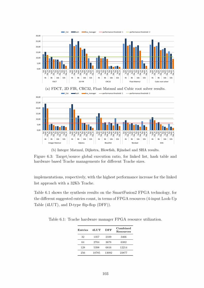
0,00
5,00
10,00
15,00
20,00
25,00
30,00
list
has
h
hw
_m
lis
t h
ash
h
w_m
lis
t h
ash
h
w_
m
list
has
h
hw
_m
list
has
h
hw
_m
lis
t h
ash
h
w_m
lis
t h
ash
h
w_
m
list
has
h
hw
_m
list
has
h
hw
_m
list
has
h
hw
_m
lis
t h
ash
h
w_
m
list
has
h
hw
_m
list
has
h
hw
_m
list
has
h
hw
_m
lis
t h
ash
h
w_
m
list
has
h
hw
_m
list
has
h
hw
_m
lis
t h
ash
h
w_
m
list
has
h
hw
_m
list
has
h
hw
_m
4k 8k 16k 32k 4k 8k 16k 32k 4k 8k 16k 32k 4k 8k 16k 32k 4k 8k 16k 32k
FDCT 2D FIR CRC32 Float Matmul Cubic root solver
l_list hash hw_manager performance threshold 1 performance threshold 2
(a) FDCT, 2D FIR, CRC32, Float Matmul and Cubic root solver results.
0,00
5,00
10,00
15,00
20,00
25,00
30,00
list
has
h
hw
_m
lis
t h
ash
h
w_m
lis
t h
ash
h
w_
m
list
has
h
hw
_m
list
has
h
hw
_m
list
has
h
hw
_m
lis
t h
ash
h
w_
m
list
has
h
hw
_m
list
has
h
hw
_m
list
has
h
hw
_m
lis
t h
ash
h
w_
m
list
has
h
hw
_m
list
has
h
hw
_m
lis
t h
ash
h
w_
m
list
has
h
hw
_m
list
has
h
hw
_m
list
has
h
hw
_m
lis
t h
ash
h
w_
m
list
has
h
hw
_m
list
has
h
hw
_m
4k 8k 16k 32k 4k 8k 16k 32k 4k 8k 16k 32k 4k 8k 16k 32k 4k 8k 16k 32k
Integer Matmul Dijkstra Blowfish Rjindael SHA
l_list hash hw_manager performance threshold 1 performance threshold 2
(b) Integer Matmul, Dijkstra, Blowfish, Rjindael and SHA results.
Figure 6.3: Target/source global execution ratio, for linked list, hash table andhardware based Tcache managements for different Tcache sizes.
implementations, respectively, with the highest performance increase for the linkedlist approach with a 32Kb Tcache.
Table 6.1 shows the synthesis results on the SmartFusion2 FPGA technology, forthe different suggested entries count, in terms of FPGA resources (4-input Look-UpTable (4LUT), and D-type flip-flop (DFF)).
Table 6.1: Tcache hardware manager FPGA resource utilization.
Entries 4LUT DFF CombinedResources
32 1357 2109 3466
64 2704 3678 6382
128 5398 6816 12214
256 10785 13092 23877
103

6.3 Non-Intrusive DBT Acceleration Module
To introduce hardware acceleration into DBT and complying with the five premisesidentified in Section 6.1, a DBT acceleration architecture is proposed and its inte-gration tested and evaluated in the following sections. Following the debug monitorhardware approach, a similar hardware module is suggested. By design, this type ofmechanism already addresses the (1) flexibility and (3) non-intrusiveness premisesfrom Section 6.1. Regarding (1) flexibility, the mechanism acts by detecting readand/or write accesses to configurable address locations, triggering the execution ofdiverse actions. Hence, it may be applied in multiple scenarios, from CC handling,to detect peripherals access. On (3) non-intrusiveness concerns, the method doesnot require any architectural modification neither ISA extension since it operateson regular architecture functionalities: address accesses and interrupt/exceptionhandling. To address the (2) scalability problem, the proposed approach shoulddeliver an adequate number of address comparators, which is possible to achieveby taking benefit from the FPGA reconfigurability.
6.3.1 Architecture
The proposed architecture functionality relies on a central module which is respon-sible for sniffing bus accesses and addresses, thus hereafter referred to as "sniffer".This sniffer module is placed in between the MSS and the data memory, in or-der to sniff read and write accesses to configurable memory addresses. Due tothis integration, the MSS is not aware of the modules, on what concerns memoryaccesses, neither requires modification of the existent hardware or architecture.It is also integration-friendly because it allows easy functionality addition to thesystem without modification on the DBT kernel. This approach, contrary to thestate of the art, does not requires any ISA extensions, tightly-coupled peripheralsor architectural modification. It requires however, configurable hardware in orderto be deployed, but since it is architecturally non-intrusive it can be used on anyCOTS SoC with FPGA fabric.
The sniffer’s architecture and interface is depicted in Figure 6.4. It is deployedin the FPGA fabric between the MSS and a memory block where the sourcearchitecture data memory shall be allocated. The instantiated memory block ispart of the FPGA’s RAM memory resources and has a simple and generic interface
104

Memory Bus Interface
Sniffer Bus Interface
Memory Bus Interface
Bus Sniffer
Sniffer Bus Interface
memorylow levelcontrol
memorylow levelcontrol
Sniffer Logic
Block RAM
(source data
memory)Write data
Read data
Figure 6.4: Non-intrusive hybrid acceleration architecture.
through address bus, read and write data lines plus write and read enable.
The sniffer has two MSS bus interfaces, one designated to the memory and anotherfor sniffer configuration and operation. The bus interfaces used were the AMBA3 AHB-Lite for both. Regarding the memory bus interface, it is known to theMSS as a regular and common memory access, and during DBT operation itbehaves as one. The address line and the access signals are monitored throughthe sniffer logic, in order to identify accesses to sensitive memory addresses, andtrigger an action if that is the case. Read and write access must be distinguishedand handled accordingly: while a write access might just require an action tobe triggered over the new value, a read access might require the execution of anaction before the value being read. This requires that the read action must beinterrupted or putted on hold before the modification take place and resumedafter. The most efficient way to trigger the execution of those action in the MSS isthrough an exception or interrupt. Both possibilities are valid, however, a specifictype of exception which particularly fits this application case, is the bus fault,because (1) it may be directly generated through the bus interface signals, (2) it isnatively generated after a failed memory access and (3) upon its happening thereare already mechanism which result in the re-execution of the failed instruction,which is particularly useful to the read access application of the sniffer.
Hence, an exception should be generated before a matching read access and aftera write access, so that during a memory read any old values may be updatedor copied to the target address, while during a memory write the actions to beperformed act on top of the fresh data.
105
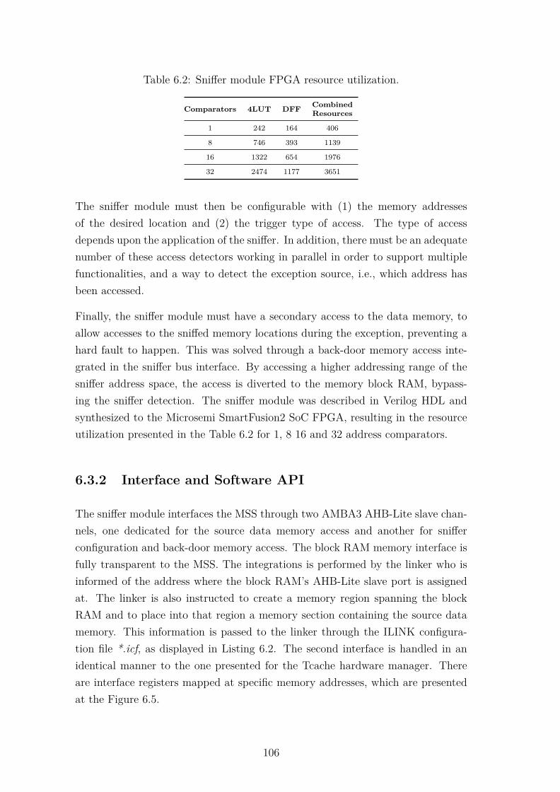
Table 6.2: Sniffer module FPGA resource utilization.
Comparators 4LUT DFF CombinedResources
1 242 164 406
8 746 393 1139
16 1322 654 1976
32 2474 1177 3651
The sniffer module must then be configurable with (1) the memory addressesof the desired location and (2) the trigger type of access. The type of accessdepends upon the application of the sniffer. In addition, there must be an adequatenumber of these access detectors working in parallel in order to support multiplefunctionalities, and a way to detect the exception source, i.e., which address hasbeen accessed.
Finally, the sniffer module must have a secondary access to the data memory, toallow accesses to the sniffed memory locations during the exception, preventing ahard fault to happen. This was solved through a back-door memory access inte-grated in the sniffer bus interface. By accessing a higher addressing range of thesniffer address space, the access is diverted to the memory block RAM, bypass-ing the sniffer detection. The sniffer module was described in Verilog HDL andsynthesized to the Microsemi SmartFusion2 SoC FPGA, resulting in the resourceutilization presented in the Table 6.2 for 1, 8 16 and 32 address comparators.
6.3.2 Interface and Software API
The sniffer module interfaces the MSS through two AMBA3 AHB-Lite slave chan-nels, one dedicated for the source data memory access and another for snifferconfiguration and back-door memory access. The block RAM memory interface isfully transparent to the MSS. The integrations is performed by the linker who isinformed of the address where the block RAM’s AHB-Lite slave port is assignedat. The linker is also instructed to create a memory region spanning the blockRAM and to place into that region a memory section containing the source datamemory. This information is passed to the linker through the ILINK configura-tion file *.icf, as displayed in Listing 6.2. The second interface is handled in anidentical manner to the one presented for the Tcache hardware manager. Thereare interface registers mapped at specific memory addresses, which are presentedat the Figure 6.5.
106

1 ...2 /*-Block RAM Memory Region-*/34 define symbol __ICFEDIT_region_RAM2_start__ = 0x30000000;5 define symbol __ICFEDIT_region_RAM2_end__ = 0x30004FFF;67 define region RAM2_region = mem:[from __ICFEDIT_region_RAM2_start__
to __ICFEDIT_region_RAM2_end__];89 place in RAM2_region { section SEC_RAM_8051};
10 ...
Listing 6.2: Linker configuration file (.icf) snippet.
The register at base address 0x51000000, SNIFFER_CTR_REG, controls thegeneral functionality of the sniffer module. The value 0x00000000 disables the snif-fer while 0x00000001 enables its operation. Register SNIFFER_CMP_MATCH_-REG holds the information of the access matches that occurred. Each of its bitsis associated with the equivalent comparator. Upon an access match, the bitcorresponding to the match comparator is set. The register SNIFFER_TYPE_-MATCH_REG holds the information of the type of match that occurred on the
......
0x51080000 MEMORY BACK-DOOR ACCESS
source data memoryback-door access
...
...0x51000204 ACCESS_TYPE_CONF_31
0x51000200 CMP_ADDRESS_CONF_31
comparator 31configure registers
...0x51000014 ACCESS_TYPE_CONF_0
0x51000010 CMP_ADDRESS_CONF_0
comparator 0configure registers
0x5100000C SNIFFER_CMP_EN_REG}individual enab. control
0x51000008 SNIFFER_TYPE_MATCH_REG}type of match access
0x51000004 SNIFFER_CMP_MATCH_REG}compare match flags
0x51000000 SNIFFER_CTR_REG}global control register
...
Figure 6.5: Tcache hardware manager peripheral mapping.
107

involved comparator. The value 1 signals a write access while 0 signals a readaccess. The register SNIFFER_CMP_EN_REG is used to enable or disable thecomparators individually. To enable a comparator, the equivalent bit should beset, and vice-versa. The comparators configuration registers are the CMP_AD-DRESS_CONF_n and ACCESS_TYPE_CONF_n. The address to be sniffedshould be written on the former register. The type of accesses that generates amatch is configured through the latter register: 0x0001 for read accesses, 0x0010for write accesses and 0x0011 for both.
A simple API, similar to the one presented for the hardware Tcache manager,was also created. On a comparator match event a bus access fault exceptionis generated by the sniffer in order to call a handled and execute the requiredactions. On the target processor used, that exception is the bus fault exception,more specifically a data abort which natively occurs when an error response isreceived on a transfer in the AHB interfaces during a data read/write.
The procedure followed to handle an address match event is defined a follows:
1. Read the SNIFFER_CMP_MATCH_REG register to identify which com-parator matched an address access. In the case that none of the bits is set,the exception was not caused by the sniffer module and should be handleraccordingly.
2. Read the SNIFFER_TYPE_MATCH_REG register to determine whichtype of access (read or write) caused the match. If the comparator is knownto have a read only or write only configuration, this step might be skipped.
3. Perform the necessary actions by calling the appropriate helper functions tohandle the exception.
4. Clear address match bit on register SNIFFER_CMP_MATCH_REG.
The sniffer module’s functionalities will be demonstrated in the following sections,trough its application in different case scenarios: to handle condition codes, remapperipherals and provide interrupt support to the DBT engine.
108
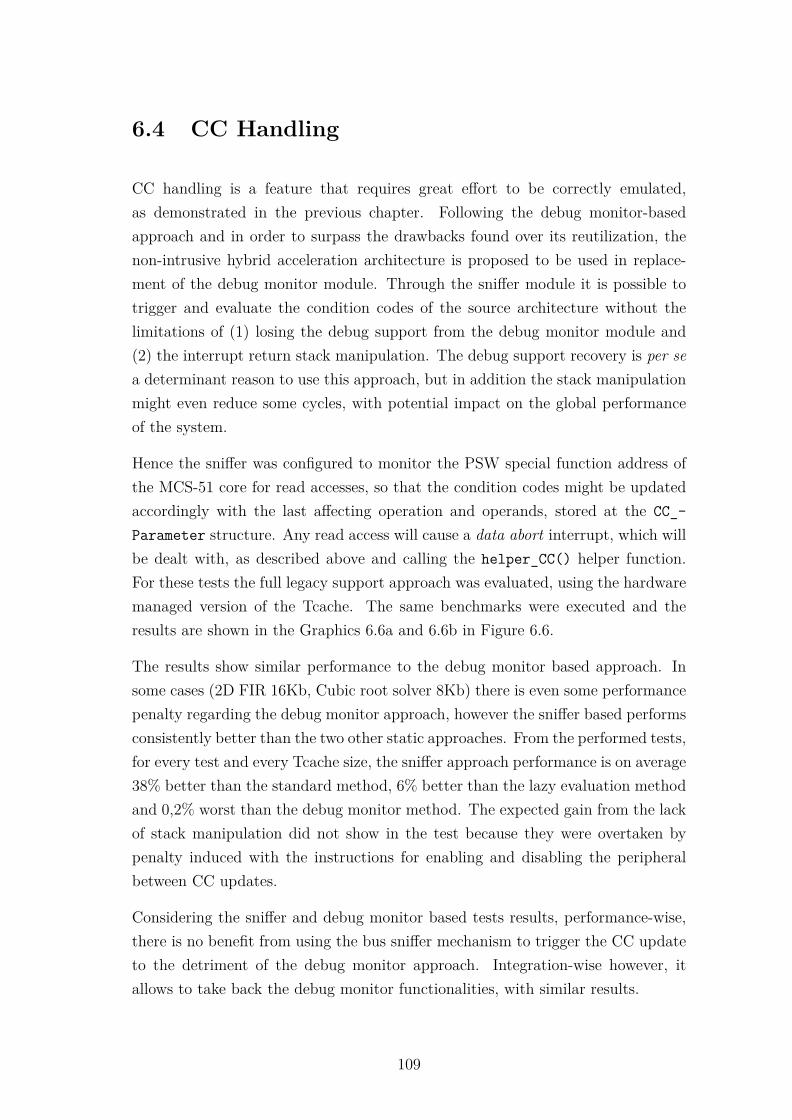
6.4 CC Handling
CC handling is a feature that requires great effort to be correctly emulated,as demonstrated in the previous chapter. Following the debug monitor-basedapproach and in order to surpass the drawbacks found over its reutilization, thenon-intrusive hybrid acceleration architecture is proposed to be used in replace-ment of the debug monitor module. Through the sniffer module it is possible totrigger and evaluate the condition codes of the source architecture without thelimitations of (1) losing the debug support from the debug monitor module and(2) the interrupt return stack manipulation. The debug support recovery is per sea determinant reason to use this approach, but in addition the stack manipulationmight even reduce some cycles, with potential impact on the global performanceof the system.
Hence the sniffer was configured to monitor the PSW special function address ofthe MCS-51 core for read accesses, so that the condition codes might be updatedaccordingly with the last affecting operation and operands, stored at the CC_-Parameter structure. Any read access will cause a data abort interrupt, which willbe dealt with, as described above and calling the helper_CC() helper function.For these tests the full legacy support approach was evaluated, using the hardwaremanaged version of the Tcache. The same benchmarks were executed and theresults are shown in the Graphics 6.6a and 6.6b in Figure 6.6.
The results show similar performance to the debug monitor based approach. Insome cases (2D FIR 16Kb, Cubic root solver 8Kb) there is even some performancepenalty regarding the debug monitor approach, however the sniffer based performsconsistently better than the two other static approaches. From the performed tests,for every test and every Tcache size, the sniffer approach performance is on average38% better than the standard method, 6% better than the lazy evaluation methodand 0,2% worst than the debug monitor method. The expected gain from the lackof stack manipulation did not show in the test because they were overtaken bypenalty induced with the instructions for enabling and disabling the peripheralbetween CC updates.
Considering the sniffer and debug monitor based tests results, performance-wise,there is no benefit from using the bus sniffer mechanism to trigger the CC updateto the detriment of the debug monitor approach. Integration-wise however, itallows to take back the debug monitor functionalities, with similar results.
109

0,00
5,00
10,00
15,00
20,00
25,00
30,00 st
and
ard
tr
ad_l
z d
eb
ug_
mo
n
snif
f st
and
ard
tr
ad_l
z d
eb
ug_
mo
n
snif
f st
and
ard
tr
ad_l
z d
eb
ug_
mo
n
snif
f st
and
ard
tr
ad_
lz
de
bu
g_m
on
sn
iff
stan
dar
d
trad
_lz
d
eb
ug_
mo
n
snif
f st
and
ard
tr
ad_
lz
de
bu
g_m
on
sn
iff
stan
dar
d
trad
_lz
d
eb
ug_
mo
n
snif
f st
and
ard
tr
ad_
lz
de
bu
g_m
on
sn
iff
stan
dar
d
trad
_lz
d
eb
ug_
mo
n
snif
f st
and
ard
tr
ad_l
z d
eb
ug_
mo
n
snif
f st
and
ard
tr
ad_l
z d
eb
ug_
mo
n
snif
f st
and
ard
tr
ad_l
z d
eb
ug_
mo
n
snif
f
stan
dar
d
trad
_lz
de
bu
g_m
on
sn
iff
stan
dar
d
trad
_lz
d
eb
ug_
mo
n
snif
f st
and
ard
tr
ad_
lz
de
bu
g_m
on
sn
iff
stan
dar
d
trad
_lz
d
eb
ug_
mo
n
snif
f
stan
dar
d
trad
_lz
d
eb
ug_
mo
n
snif
f st
and
ard
tr
ad_
lz
de
bu
g_m
on
sn
iff
stan
dar
d
trad
_lz
d
eb
ug_
mo
n
snif
f st
and
ard
tr
ad_l
z d
eb
ug_
mo
n
snif
f
4k 8k 16k 32k 4k 8k 16k 32k 4k 8k 16k 32k 4k 8k 16k 32k 4k 8k 16k 32k
FDCT 2D FIR CRC32 Float Matmul Cubic root solver
standard lazy_ev debug_mon sniffer performance threshold 1 performance threshold 2
(a) FDCT, 2D FIR, CRC32, Float Matmul and Cubic root solver results.
0,00
5,00
10,00
15,00
20,00
25,00
30,00
stan
dar
d
trad
_lz
d
ebu
g_m
on
sn
iff
stan
dar
d
trad
_lz
d
ebu
g_m
on
sn
iff
stan
dar
d
trad
_lz
d
ebu
g_m
on
sn
iff
stan
dar
d
trad
_lz
d
ebu
g_m
on
sn
iff
stan
dar
d
trad
_lz
d
ebu
g_m
on
sn
iff
stan
dar
d
trad
_lz
d
ebu
g_m
on
sn
iff
stan
dar
d
trad
_lz
d
ebu
g_m
on
sn
iff
stan
dar
d
trad
_lz
d
ebu
g_m
on
sn
iff
stan
dar
d
trad
_lz
d
ebu
g_m
on
sn
iff
stan
dar
d
trad
_lz
d
ebu
g_m
on
sn
iff
stan
dar
d
trad
_lz
d
ebu
g_m
on
sn
iff
stan
dar
d
trad
_lz
d
ebu
g_m
on
sn
iff
stan
dar
d
trad
_lz
d
ebu
g_m
on
sn
iff
stan
dar
d
trad
_lz
d
ebu
g_m
on
sn
iff
stan
dar
d
trad
_lz
d
ebu
g_m
on
sn
iff
stan
dar
d
trad
_lz
d
ebu
g_m
on
sn
iff
stan
dar
d
trad
_lz
d
ebu
g_m
on
sn
iff
stan
dar
d
trad
_lz
d
ebu
g_m
on
sn
iff
stan
dar
d
trad
_lz
d
ebu
g_m
on
sn
iff
stan
dar
d
trad
_lz
d
ebu
g_m
on
sn
iff
4k 8k 16k 32k 4k 8k 16k 32k 4k 8k 16k 32k 4k 8k 16k 32k 4k 8k 16k 32k
Integer Matmul Dijkstra Blowfish Rjindael SHA
standard lazy_ev debug_mon sniffer performance threshold 1 performance threshold 2
(b) Integer Matmul, Dijkstra, Blowfish, Rjindael and SHA results.
Figure 6.6: Target/source global execution ratio, for the standard, lazy evalua-tion, debug monitor and sniffer based CC evaluation, using the hardware managedTcache, for different Tcache sizes.
The resemblance in the performance tests results from the similarity of the meth-ods. Both rely on an external trigger source to an interrupt/exception and con-sequent CC evaluation function call. Both methods also use the CC-Parameterstructure (similarly to the other two methods) to save the operands and operationsfor CC emulation.
The structure manipulation during execution is heavy and time consuming, how-ever can not be avoided with the evaluated methods. One option to avoid its useis the full emulation of the CC affecting instructions through a helper functionduring execution However such option may have other negative impacts on perfor-mance, and CC emulation would still be necessary. If reconfigurable hardware isavailable, a full source ALU replication as an acceleration module is suggested tobe evaluated, using the sniffer module to trigger the PSW copy from the acceler-ator to its source memory location. This option, despite being more ’brute-force’
110

driven provides instant CC update and avoids the costs of emulation. Due to timelimitations this approach was not attempted, and thus it is suggested as futurework.
6.5 Peripheral Remapping
The sniffer module was also tested for functionality expansion and peripheral sup-port, which is of great importance when dealing with embedded systems. Periph-erals access is a feature with a great dynamic behavior. This dynamic affects itssupport on DBT because despite accesses can be predicted during translation, theperformance penalty of such detections ripples across the whole system (requiresverifying the addresses of every gen_ld(), gen_st() and related micro Ops). Theimplemented non-intrusive mechanism deals with it with ease as demonstrated inthis section.
Among the multiple peripherals included in the MCS-51 architecture (e.g., timers,GPIO, Universal Asynchronous Receiver/Transmitter (UART)), the UART serialport communication device was selected. The functional verification of this periph-eral is easy to attain, and it is perhaps the mostly used data transfer mechanismon legacy MCS-51 code.
In order to remap source into target peripherals, the supported peripherals of thesource hardware must be known, as well as its configuration options, control andstatus registers and command bits. It is also necessary, although not mandatory,to find similar peripherals on the target architecture device. If no replacementperipherals are available the reconfigurable FPGA fabric might be used to deployan IP module of the peripheral to be remapped. It may also, if decided in theproject, to remap the peripheral into another type of peripheral, as long as theinterfaces, type of data and type of transfer are possible to mutate between theoriginal and the destination peripheral. Taking the example the UART port, itmight be remapped and assigned for instance to a SPI device, as long as theoriginal behavior of the source code remains intact. In this application case, thesource UART port was mapped to a UART port available in the target Cortex-M3platform.
On what concerns the MCS-51 UART configuration, there is one control regis-ter, the SCON(0x98), plus the transfer buffer SBUF(0x99). There are thee addi-
111

tional registers involved, for baud rate generation purposes, the RCAP2H(0xCB),RCAP2L(0xCA) and the T2CON(0xC8), which refer to the reload and capture timer2 high and low value and the timer 2 control register, respectively. Every of thesefive registers must be added and monitored by the sniffer, thus a comparator mustbe assigned to each of them. A write access monitoring generated the type ofexception that allows to know which configuration is being set for each of the reg-isters. Only the SBUF requires a read and write access monitoring, because it isa shadowed register for both send and receive transfers. The exception triggeredby any write to these registers will provide the opportunity to sniff the appliedconfiguration by the source binaries, and replicate it in the assigned target UART.
For the purpose of testing the UART peripheral remapping, a simple UART pollingtransfer program was developed and tested on a native MCS-51 core (ATMEL89C51IC2) with the message:
"Hello! is it me you’re looking for?!\n-MCS-51 - by polling\n"
The binaries were then set to translation and peripheral remapping. The describedremapping configurations were added in the envReset() virtual method of the de-rived Translator class, which is also used to perform the necessary initializations.The function on the Listing 6.3 is called when the SBUF register is written withthe byte to send.
The intercepted byte is then forwarded to the Cortex-M3 UART through thevendor provided API for a polled transmission. After completed the transmission,the TI flag of the SCON, which signals a transmit complete, is set and the exceptionreturns to the execution of the translated code.
1 void CTranslator8051::helper_SBUF_WRITE(void){23 uint8_t tmp;45 tmp = BACKDOOR_GET_UINT8_T(env.dataMem[SBUF]);6 MSS_UART_polled_tx(&g_mss_uart1, (const uint8_t *)&tmp, 1);78 env.dataMem[SCON] |= 0x02; //set the TI flag to 1;9 return;
10 }
Listing 6.3: SBUF write action helper function.
The translated code will eventually read and verify the TI flag in a loop (polled
112

Hardware
UARTTranslation Execution
Exception
Handler
execute after translation
SBUF write triggers exception
send byte
send byte
polling until finish sending byte
return to execution
end of transferverify transmit complete
Figure 6.7: Peripheral emulation sequence diagram.
transmission) and since the byte was sent already it will pass the condition andproceed with the program execution to send the next byte. The described sequenceof events is presented in Figure 6.7, where the code translation and execution do-mains are distinguished, together with the exception handler routine. The hard-ware UART device was also added to the diagram to express its role between theinteractions as well as its parallel execution. The circle on top of the "Translation"domain expresses its role similar to an "Actor" since it is the principal process inthe sequence due to the DBT engine being implicitly represented on it. The sourcebinaries were loaded and translated on the DBT system. The target UART portwas connected to a computer and serial port terminal tool was used to receive and
Figure 6.8: Received message from the MCS-51 remapped UART transmission bypolling.
113

display the message. The received message and port settings (i.e., baud rate, databits, parity bit and stop bit) are shown in Figure 6.8. The configuration of theserial port was correctly deciphered and applied to the target UART port, and theperipheral remapping mechanism proved to be functional.
6.6 Interrupt Support
The presented functionality of the sniffer module is explored in this section forinterrupt support. For exemplification purposes, and similarly to the previoussection, a type of interrupt present in the source architecture was selected to beemulated. The UART interrupt was elected for the demonstration because italso produces a visible output that eases functionality confirmation and becauseit builds up on top of the demonstrated peripheral, as well as demonstrating thescalability of the non-intrusiveness architecture, spanning the peripheral supportedmodes and creating a case which intercalates the peripheral with the interruptsupport. A simple program for sending bytes through the serial port based oninterrupt was written and compiled for the MCS-51. The message to send was thefollowing:
"Hello! is it me you’re looking for?!\n-MCS-51 - by interrupt\n"
On what concerns the serial port communication, the configuration registers mon-itoring and mapping to the target UART remains the same, but with the extrastep to write to the register IEN, Interrupt Enable control, required to configurethe interrupt mechanism to be used together with the serial port.
Generally the interrupt handling mechanism is based on a halt in the data-path,after completion of the already fetched instructions, and a jump to a code locationwhere lies the ISR. There are context saving operations that must take place inorder to not affect the normal program flow data, since this is an unpredictableevent not involving a caller that usually saves the relevant process data. Uponprocessing of the ISR, the context data is restore and the processor resumes theexecution of the code. To emulate this mechanism into DBT there are someconsiderations to take into account. On what concerns the interrupt cause andprocessing:
1. Similarly to the peripherals, the interrupt source must be also remapped toa target interrupt, so that no polling is involved in the event registration and
114
the source translated code has available processing resources to perform itseventual computations.
2. The source ISR code locations must be known, in order to be located andtranslated.
3. A mechanism to interrupt the execution of translated code and give place tothe execution the ISR must be provided.
4. A mechanism to interrupt the normal DBT cycles of code Translation andExecution without disrupting it must also be provided, so that the sourceISR may be translated and executed in the middle of the DBT flow andposteriorly return it.
On what regards the context switch the considerations are:
5. The integrity of the source translated code under execution must be assured,in order to maintain code correctness. Contrary to the native executionwhere there is a concept of atomicity associated with each instruction, on aone-to-many type of translator that concept is hard to replicate.
6. The interrupt emulation process must also not interfere with the architecturalresources used in the DBT process, namely, the intermediary work registersused during code execution, the execution stack and the return address.
These considerations were taken into account and the proposed interrupt emulationmechanism addresses is conformable with them. The target UART peripheral isconfigured for an interrupt based operation, which allows to (1) use the targetinterrupt source to trigger the source interrupt handling action. On the MCS-51,(2) the ISR code locations are determined by the architecture and for the serialport interrupt, it is the address 0x23. Hence after a UART remapping, (3) if aninterrupt of the target UART occurs, the code execution is halted and the sourceISR code to be translated and executed from, is known to be at the source address0x23.
In order to not break the ordinary DBT flow, a supplementary DBT process iscreated for the purpose of translating and setting the execution of ISR code. It isimplemented as a method trigger_interrupt(uint16_t isr_addr) in the baseTranslator class, and received the ISR location address as parameter. When a (4)remapped interrupt occurs, this method is called and saves the current env.PC(which controls the DBT flow), replaces it with the ISR address parameter and
115
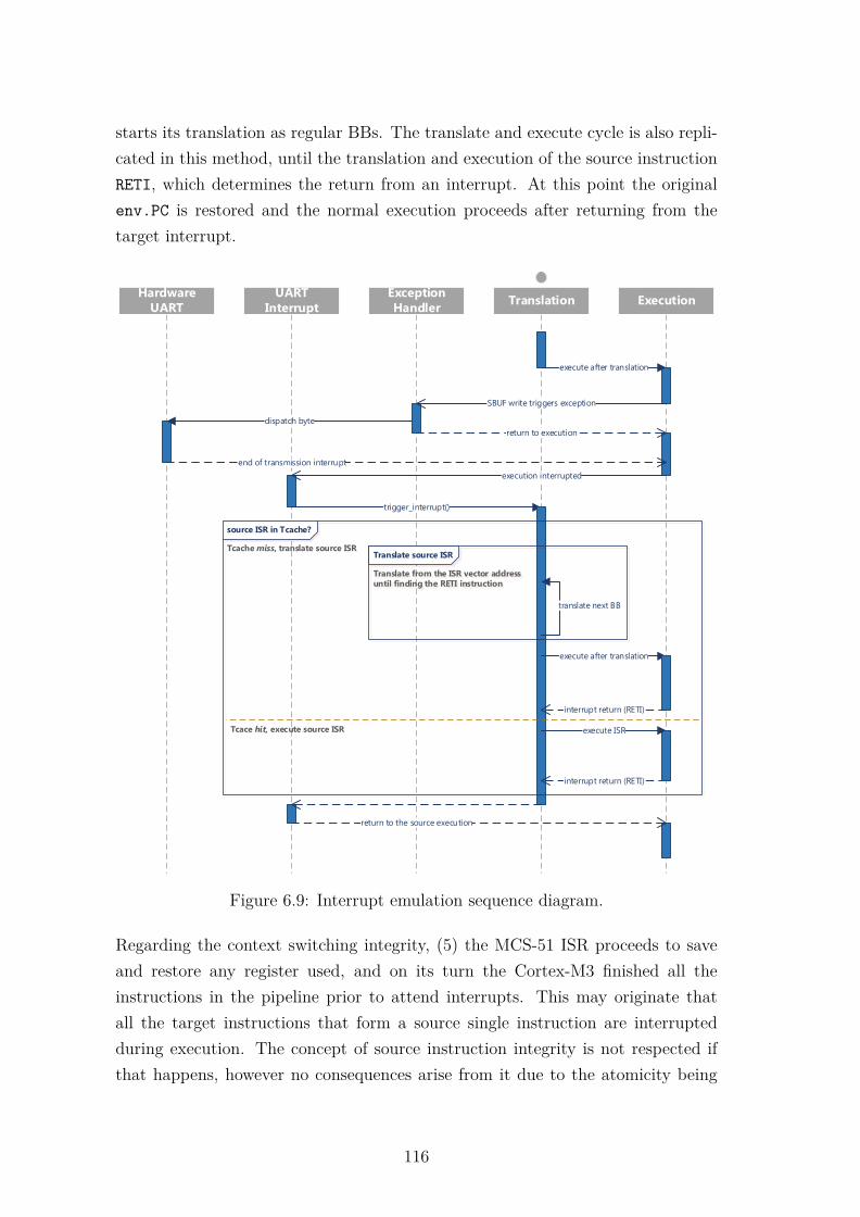
starts its translation as regular BBs. The translate and execute cycle is also repli-cated in this method, until the translation and execution of the source instructionRETI, which determines the return from an interrupt. At this point the originalenv.PC is restored and the normal execution proceeds after returning from thetarget interrupt.
Hardware
UARTTranslation Execution
Exception
Handler
execute after translation
SBUF write triggers exception
dispatch byte
return to execution
UART
Interrupt
end of transmission interrupt
execution interrupted
trigger_interrupt()
translate next BB
execute after translation
interrupt return (RETI)
return to the source execution
Translate source ISR
Translate from the ISR vector addressuntil finding the RETI instruction
source ISR in Tcache?
Tcace hit, execute source ISR
Tcache miss, translate source ISR
execute ISR
interrupt return (RETI)
Figure 6.9: Interrupt emulation sequence diagram.
Regarding the context switching integrity, (5) the MCS-51 ISR proceeds to saveand restore any register used, and on its turn the Cortex-M3 finished all theinstructions in the pipeline prior to attend interrupts. This may originate thatall the target instructions that form a source single instruction are interruptedduring execution. The concept of source instruction integrity is not respected ifthat happens, however no consequences arise from it due to the atomicity being
116

Figure 6.10: Received message from the MCS-51 remapped UART transmissionby interrupt.
neatly broken at the target instructions. The last concern is addressed by (6)the target processor context saving during interrupt attendance and by the choiceof preserved registers for working registers. After an interrupt event the ARMv7architecture pushes the context registers (and also the scratch registers) into thestack, restoring them during interrupt return.
Figure 6.9 illustrates the interrupt support sequence diagram. This diagram, inaddition to the one presented in Section 6.5, has the "UART Interrupt" domain,which represents the target ISR handler routine. The initial part of the diagram,which depends on the sniffer module, is similar to the previous diagram, but nowthe exception handler initiates the transfer and does not waits until its end. In-stead, the control is returned to the Execution of the source binaries. From thereon, the proposed ISR handling mechanism takes place until the end of the execu-tion of the source ISR handler. After returning from the target UART Interruptthe sequence is repeated, but in case the source ISR is already at Tcache, thenno code translation is performed and it is directly executed. If, the SBUF is writ-ten during the execution of the source ISR, the peripheral mapping mechanism istriggered, the interrupt handling halted and a new byte is sent to transfer, andthen the ISR is resumed. The results of this implementation are shown in Figure6.10, where the new message is shown in the serial port terminal tool, after beingcorrectly received.
6.7 Conclusions
In this chapter the functionality extension of the DBT engine using external hard-ware support was addressed. A Tcache partially deployed in hardware and a COTScompliant architecture for DBT functionality extension and hardware acceleration
117

were presented.
The Tcache hardware management with a circular BB registry dismisses the useof a hash table or other secondary software management mechanisms, resultingin significant performance enhancement, compared to the previously presentedhardware-only management methods, for every test scenario. The hardware look-up-table has a reduced and fixed insertion and search time, leading to betterperformance and scalability. The results are on average 25% and 26% better thanthe linked list and hash table implementations, respectively
The proposed acceleration and functionality extension architecture is based on anexternal hardware module, integrated as a bus sniffer, which results in a hardwareand non-intrusive execution flow technique, never tried before in the state of theart. The bus sniffer may be used to trigger software or hardware components, basedon the source architecture memory accesses, providing great flexibility on the typeof application to serve without disturbing the base DBT program flow. Threetypes of application to the proposed bus sniffer were presented: to handle the CC,to remap source peripherals and to provide interrupt support. On all the use casesthe bus sniffer approach functionality was tested with a practical demonstrator.The efficiency of the approach may only be evaluated in the CC handling case dueto lack of comparative results for the peripheral remapping and interrupt supportcases. However, the type of cases used, which have exact timings and sequences(e.g., baud rate, sending order), posing an increased integration challenge, provethe validity of the approach on what concerns functionality correctness. An in-depth discussion on each of the application cases of the bus sniffer now follows.
Regarding the presented bus sniffer based CC handling, the results are similarto the debug monitor based approach. For a full legacy support execution, theperformance is superior to the two other software-only approaches. Using thismethod for CC evaluation allows the use of the available debug resources whilereducing the CC handling time.
For the peripheral remapping, the presented approach attained a mechanism toemulate and remap peripherals in DBT. The mechanism is transversal for othercommunication peripherals and flexible enough to extend the supported function-alities beyond the ones demonstrated in this application case. On what concernstimers, its direct applicability is not so clear. The configuration sniffing and remap-ping of the source timers to the target timers is supported (as long as the code tomap the equivalent configurations is added to the translator), however and due to
118

differences of clock domains, performance penalties and general de-synchronizationbetween the native and translated execution, this topic requires further efforts inorder to be presented.
Regarding interrupt support, we propose a novel mechanism to handle interruptsin DBT, by using target interrupts trigger to execute source ISR, in a fully dynamicmanner. Interrupt latency was not addressed because this study is far from real-time requirement systems.
Considering the increasing variability and configuration complexity added to thealready complex DBT system with the presented functionalities, it is now manda-tory to promote, along with the DBTor, dedicated tools for managing the complex-ity and easing the final systems customization, toward a unified DBT framework.This goal will be address in the next chapter.
119

120

Chapter 7
Automation Enablement throughDSL
Embedded systems design for industrial application solutions is a highly complextopic due to the challenge of integrating multiple technologies into a single solu-tion, the inherent complexity of the problems to be solved and also because theproposed solutions often require a great level of interoperability among their com-ponents and also the outside world. DBT has been used as a tool to deal withsuch interoperability issues, e.g., legacy support, virtualization and secure execu-tion, among others, as already presented in Chapter 1. However its integration inthe industry as an end-product is hampered by the required intricate variabilitymanagement. To address these issues and in an attempt to empower DBT uti-lization through an interoperability-providing tool, it is proposed a model-drivenDSL modeling language for DBT architectures. The developed DSL proved tobe efficient to model the in-house DBT engine, and FAT-DBT, a framework forready-to-use DBT solutions was obtained. FAT-DBT provides design validation,easy configuration of customizable DBT parameters and components, as well ascode generation features.
7.1 Introduction
Some of the big difficulties in todays’ industrial solutions design is the high com-plexity of the systems and the variability management challenge [136] that theintegration of multiple technologies poses. This is partially caused by the inherent
121

complexity of the problems that need to be solved but also because the solutionsoften require a great level of interoperability between the system’s elements andthe outside world. A long known solution to deal with such interoperability is-sues is BT. In this IoT advent, DBT may become an emerging technology dueto the interoperability it may provide to heterogeneous industrial environments,and also for its usability as a tool to support competitors products’ firmware on amarket race perspective [45,137]. In spite of being successfully deployed in general-purpose systems to support cross-ISA binary compatibility, dynamic optimization,profiling, virtualization, secure execution or debugging environment, in embeddedsystems, binary translation has been avoided mainly due to performance, memoryand power overheads [45,61,94].
However, DBT utilization as an end-product in the industry has been hamperedby the complexity of the subject and its associated variability management, whichbrings configuration challenges into the final solution [94]. The accessible andprofitable use of DBT requires design automation paradigms and variability man-agement solutions, expanding its usage for DBT laymen. In this sense, a DBTframework must provide support for several source and target architectures, op-tional execution features (e.g., code profiling, type of Tcache management, periph-eral remapping, etc.), resource utilization settings (e.g., available memory size,Tcache size), design validation and consequent automatic code generation.
In this chapter a model-driven DSL modeling language for DBT architecturesis presented, aiming to improve complexity management, design validation andindustry interoperability. Along with the DSL modeling language a frameworknamed FAT-DBT was also developed, for ready-to-use DBT solutions, providingeasy configuration and code generation features, even for DBT laymen users. Theremaining of this chapter is organized as follows: Section 7.2 introduces the DSLsubject theme; Section 7.3 presents the modeling Elaboration Language (EL) andthe FAT-DBT framework; the DBT modeling process with the EL is explained inSection 7.4; Section 7.5 describes the implementation of the DBT system using theobtained framework and in Section 7.6 and 7.7 the work evaluation is presentedand the conclusions are exposed, respectively.
122
7.2 DSL for DBT
A DSL is a programming language that targets a specific problem domain. ADSL should not provide features to solve every kinds of problems found in a cer-tain domain, but instead should make it easier to deal with the problems of thedomain it is specific for [138]. The usage of a DSL over a GPL is justified byseveral advantages such as (1) gains on expressiveness on the target domain, (2)ease of use, (3) enhanced productivity, (4) reliability, (5) maintainability, (6) easierreasoning and validation, and (7) the direct involvement of domain experts [139].The effort required to develop a DSL is however quite hard, as it requires a lot oftechnical experience and great understanding of the domain. Nonetheless, afterimplemented, the development work usually pays off [140]. The interest in DSLsfor GP [141] and in MDD [142] is becoming wider, as they promote software reuseand fast development through a high abstraction level. GP purpose is to automat-ically generate a system given a set of specifications [141]. MDD is an approachused to create extensive and descriptive system models on a higher implementationabstraction, thus simplifying development and testing activities [142]. Together,these two techniques promote software reutilization and automatic code genera-tion, powering the DSL to map different models together and elaborate the finalsystem code [143].
To pursue such goal, a model-driven DSL, named EL, was developed to auto-matically generate code from the source files of a given system’s model. It isbased in the Service Component Architecture (SCA) standard, which specifiesthat a model’s components should follow a composite pattern [144]. SCA fea-tures six key elements: (1) composite, (2) component, (3) service, (4) reference,(5) property and (6) wire. A complete reference architecture can be constructedby identifying system components and their interactions, as well as the propertiesassociated to each component. The EL grammar was developed using Xtext [145],which is a framework for programming languages and domain-specific languagesdevelopment, offering a full development infrastructure including parser, linker,type-checker and compiler [146]. An auxiliary tool, Xtend [147], was also used toimplement the language validators, the code generation software and other addi-tional features. Xtend is a flexible and expressive dialect of Java, which compilesinto readable Java 5 compatible source code [147]. Both Xtend and Xtext arewidely used for DSL development and integrable with Eclipse IDE [138]. The ELdevelopment will not be covered in this thesis. The EL was used as a solution
123

for the modeling of a DBTor for embedded systems. The obtained tool, togetherwith GUI component configurators, was called Framework for Application TailoredDynamic Binary Translation - FAT-DBT.
7.3 FAT-DBT - EL and Framework Overview
The EL framework work-flow, shown in Figure 7.1, is composed by four mainstages: (1) modeling, (2) elaboration, (3) configuration and (4) code generation.During each stage a set of artifacts is created and then used in the following stages.
The modeling stage goal is to create the model that will be used as the system’sreference architecture. In this stage every component must be identified, as wellas their dependencies, properties, interfaces and relations with other components.This model must be described through the EL. Then, the model representationgoes through the model compiler, which proceeds to syntactic and semantic vali-
.elComponent
Component Component
Generated Files
.c .v.c
Modelling with EL DSL
Compiler
Elaborator
Generates
Code Generation
Generates
Executes
Configures
User
Component
InputInput
.java
.java
Source Files Elaboration Files
.c
.c
.v
Elaborates
Designs &Implements
Configuration Files
.xml
.xml
ConfigurationGenerates
Designer
Elaboration
Figure 7.1: Elaboration Language framework workflow.
124

dations. After a successful compilation, an architecture-specific Java Elaborator isgenerated, together with a set of XML configuration files, and abstract elaborationand Java classes for each component.
In the elaboration stage, the elaboration files gather the information from the wholecomponent’s behavior and how the source code for that component must be gen-erated. If there is more than one implementation available to a given component,the desired implementation should be specified in the correspondent configurationfile. Only one elaboration class per component is executed by the Elaborator.The annotation process is eased by an API that was created to fetch the desiredvalues from the configuration files and replace them within the source code files.The elaboration stage also includes the definition of the annotated source files andthe implementation of the elaboration classes (which are based on the abstractelaboration classes).
During configuration stage, it is possible to modify the component properties’values and which elaboration file will be loaded into the Elaborator. It is alsopossible to have specific properties for each elaboration which are not presentedin the reference architecture. In this case another XML file must be provided bythe developer.
Finally, the generated elaborator is executed. During this process, components’properties are fetched and the elaboration classes are loaded using Java reflexion.
EL’s Constructs
As previously stated, the EL follows a SCA, which means that an EL file containsthe following constructs: interfaces, languages and components. An interface is aset of functions that implement a service provided by a component. Componentscan be connected through bindings of services and references that follow the sameinterface type. Every declared component must have an implementation language.The language used by these components should have, in addition to a name, anannotation section where the user defines a set of characters that will be usedto define annotations in the source files. A component can be composed by aset of subcomponents, properties, references, services and a free section used tomake assignments or promoting services and/or references. It can also encloseother components and access all of their properties, references and services. Acomponent can also inherit another component. This operation transfers all the
125

Table 7.1: Available EL’s keywords.
Keyword Description
annotation Defines the character that limits the annotations.as Renames a promoted reference or service.bind Binds a reference to a service.compile Tells to compiler which is the top level component.component Defines a component.final Defines that a component has a concrete elaboration.import Imports the content of the specified file.interface Defines a set of functions used by a service or pointed by a reference.is Inherits the specified component.language Defines a language.promote Promotes a reference or service from a subcomponent to a component.properties Defines the properties set of a component.reference Defines the reference used in a promote or in a bind operation.references Defines the references set of a component.restrict Restricts the values that a property can take to a user’s defined set.service Defines the service used in a promote or in a bind operation.services Defines the services set of a component.to Connects a reference to a service in a bind operation.
content of the inherited component to the top-level component. Each propertymay have its own restriction list or range, for value filtering purposes. Later, thespecified properties will receive their values in the assignments section or at thecode generation step, through the replacement of the established annotations. Bythe definition of a composite design pattern, a component can provide one or moreservices to other components. Since a service is implemented by interface functions,a component can not have more than one service on the same interface. A referenceshould be created only when a component requires to access a subcomponent’sservice. The assignments field allows the user to set the value of componentsand subcomponents properties. In the promotes section the user can promotereferences or services of a subcomponent in order to use them in their top-levelcomponent. Furthermore, it is also possible to bind references to services in thebinds section and to specify the top-level component on the hierarchy using thekeyword compile. This specification also indicates the classes’ invocation order tothe Elaborator program. Table 7.1 presents the available EL’s keywords and theirrespective description.
126

7.4 Modeling the DBT Engine
The DBT system’s model building was supported on the theoretical and imple-mentation background on dynamic binary translation, obtained from the in-houseDBT engine development. After a thoughtful analysis of the existent deployment,several components and interfaces were identified. Moreover, several configurationpoints were found and transposed to the model through properties. The end goalof the model was to automate the system configuration, to perform architecturevalidation and to generate the final source code for the end system.
Reference Architecture
In Figure 7.2 it is represented the reference architecture model for the DBTor witha simplified representation of the most relevant interfaces. The model componentsare represented as blocks and the properties as black diamonds. The services areidentified by gray polygons and references by blue polygons. Dashed lines areused to represent interfaces between components. The composite DBTor is madeby all the other components and composites of the DBT reference architecture.
Dynamic Binary Translation Model
Source Cluster
SourceArchitecture
Decoder
SourceEnvironment
Target Cluster
Target Architecture
Generator
DBT Engine
Translator Executor
DataMemory
TCacheCCache
- Property - Reference - Service
Figure 7.2: Reference architecture.
127

Through its modeling, five main sub-components were identified, all providing themain features of the system: Ccache, Tcache, Source Cluster, Target Cluster andDBT Engine. The Source Cluster is the composite that aggregates the softwareblocks associated with the source architecture, which are Source Environment (alsocomposed by the data memory), Source Architecture and Decode. The TargetCluster is also a cluster of related software blocks, but in this case, related tothe target architecture. It is composed by the Generator and Target Architecturecomponents. The DBT Engine represents the heart of the translator. It models theintermediary layer created at run-time that implements the translation of sourcecode and execution of the target code. Therefore, it is composed by two sub-components: Translator and Executor.
7.5 Implementation
Based on the DBT reference architecture, an EL code representation was createdfor all the components and interfaces. Listing 7.1 depicts the code representationof the TranslationCache component with its properties, references and services.The component properties come with default values that can be later modifiedby the end user. The TranslationCache has a reference, r_ISA, to the targetarchitecture to define the Translation Cache word size and the service s_TCacheprovided by the Translation Cache. This service interface is represented in theListing 7.2, with its five functions: addTag, getTransAddr, getLastTransAddr,getCurrInsAddr and cacheCode.
1 component TranslationCache (cpp)2 {3 properties :4 int TCache_Size : 8192 // 20 Kbytes5 string cacheType : "Flush"6 services :7 i_TCache s_TCache8 references :9 i_ISA r_ISA
10 }
Listing 7.1: EL representation of TranslationCache component.
128

1 interface i_TCache2 {3 addTag4 getTransAddr5 getLastTransAddr6 getCurrInsAddr7 cacheCode8 }
Listing 7.2: EL representation of the i_TCache interface.
The implementation of this component is written in C++ language, therefore alanguage type entity cpp was created, where the meta-characters used to annotatethe source files are defined as ’@@’ (Listing 7.3).
1 language cpp2 {3 annotation : "@@"4 }
Listing 7.3: EL representation of C++ language.
These meta-characters are used in the source code preceding and proceeding theunique identifier of an annotation that will be replaced by its respective valueduring the elaboration process of the final sources.
Elaboration
After the EL files being compiled, the elaboration files in Java and configurationfiles in XML are generated. In this phase the annotated source code files andconfiguration files are used in the elaboration process of the final files. The typesof files used in the elaboration stage are described ahead:
• Configuration Files - The configuration files provide to the user the capa-bility of modifying the default values of the component’s properties and thesystem’s behavior through the modification of the default elaboration files.
• Annotated Sources - While building the model, the designer identifies sev-eral configuration points that should be annotated in the source code withthe meta-characters defined in the EL. The Listing 7.4 shows the annota-tions TCacheSize, cacheType and CC_type, that will be replaced by user
129

defined values during the elaboration process. These values will replace the(@@TransCache_Size@@, @@TransCache_Type@@) and @@CC_type@@ annota-tions, respectively. TCacheSize and cacheType refer to the Tcache availablesize to store translation and the type of cache management used, respec-tively, while the CC_type expresses the method used in the DBT to emulatethe source condition codes.
• Elaboration Files - The specific elaboration files for each source file hasthe annotations that should be replaced and their corresponding value. Theelaboration API provides methods to replace the annotations and generatethe final files. The annotations that were previous explained are presentedin the Listing 7.5 with the replacement methods.
1 #define TCacheSize @@TransCache_Size@@2 #define cacheType @@TransCache_Type@@3 #define CC_type @@CC_type@@
Listing 7.4: Example of annotations.
1 openAnnotatedSource (" defines .h");2 replaceAnotation (" TransCache_TSize ",
target . get_TCache_Size ());3 replaceAnotation (" TransCache_Type ", target . get_cacheType ());4 replaceAnotation (" CC_type ", target . get_CC_type ());
Listing 7.5: Elaboration file.
In the header file it is necessary to change the annotation TransCache_Size,TransCache_Type and CC_type. These annotations should be replaced by thevalue of their respective properties, previously configure by the user. The elabora-tion file also contains methods that return the names of the implemented servicesspecific for each elaboration.
7.6 Evaluation
In order to demonstrate the contribution of the EL, a reference DBT architectureframework was created, the FAT-DBT. After the system’s configuration, all sourcefiles are automatically generated and ready to be compiled. The reference modelabstracts the component’s implementation to the user but requires the system de-
130
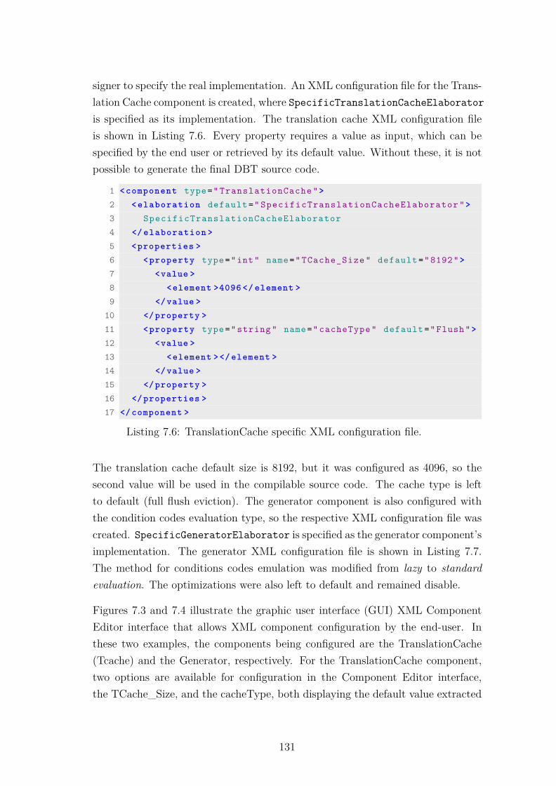
signer to specify the real implementation. An XML configuration file for the Trans-lation Cache component is created, where SpecificTranslationCacheElaboratoris specified as its implementation. The translation cache XML configuration fileis shown in Listing 7.6. Every property requires a value as input, which can bespecified by the end user or retrieved by its default value. Without these, it is notpossible to generate the final DBT source code.
1 <component type=" TranslationCache ">2 <elaboration default =" SpecificTranslationCacheElaborator ">3 SpecificTranslationCacheElaborator4 </ elaboration >5 <properties >6 <property type="int" name=" TCache_Size " default ="8192">7 <value >8 <element >4096 </ element >9 </value >
10 </property >11 <property type=" string " name=" cacheType " default ="Flush">12 <value >13 <element ></ element >14 </value >15 </property >16 </properties >17 </component >
Listing 7.6: TranslationCache specific XML configuration file.
The translation cache default size is 8192, but it was configured as 4096, so thesecond value will be used in the compilable source code. The cache type is leftto default (full flush eviction). The generator component is also configured withthe condition codes evaluation type, so the respective XML configuration file wascreated. SpecificGeneratorElaborator is specified as the generator component’simplementation. The generator XML configuration file is shown in Listing 7.7.The method for conditions codes emulation was modified from lazy to standardevaluation. The optimizations were also left to default and remained disable.
Figures 7.3 and 7.4 illustrate the graphic user interface (GUI) XML ComponentEditor interface that allows XML component configuration by the end-user. Inthese two examples, the components being configured are the TranslationCache(Tcache) and the Generator, respectively. For the TranslationCache component,two options are available for configuration in the Component Editor interface,the TCache_Size, and the cacheType, both displaying the default value extracted
131

form the XML configuration file, and accepting new configuration values, whichwill later replace the respective annotations during the code generation process.
1 <component type=" Generator ">2 <elaboration default =" SpecificGeneratorElaborator ">3 SpecificGeneratorElaborator4 </ elaboration >5 <properties >6 <property type="bool" name=" optimizations " default ="false"7 <value >8 <element ></ element >9 </value >
10 </property >11 <property type="int" name=" CC_type " default ="1">12 <value >13 <element >STANDARD </ element >14 </value >15 </property >16 </properties >17 </component >
Listing 7.7: Specific XML configuration file.
For each property, the application restricts the inputs, according to their type(defined by the EL keyword type) or possible range (set in the field Value), avoidingwrong user inputs. The same type of interface is presented for the Generatorcomponent, in Figure 7.4, presenting the configuration possibility for the CC_-type (CC evaluation mechanism) and optimizations.
Figure 7.3: XML Component Editor interface for the TranslationCache compo-nent.
132
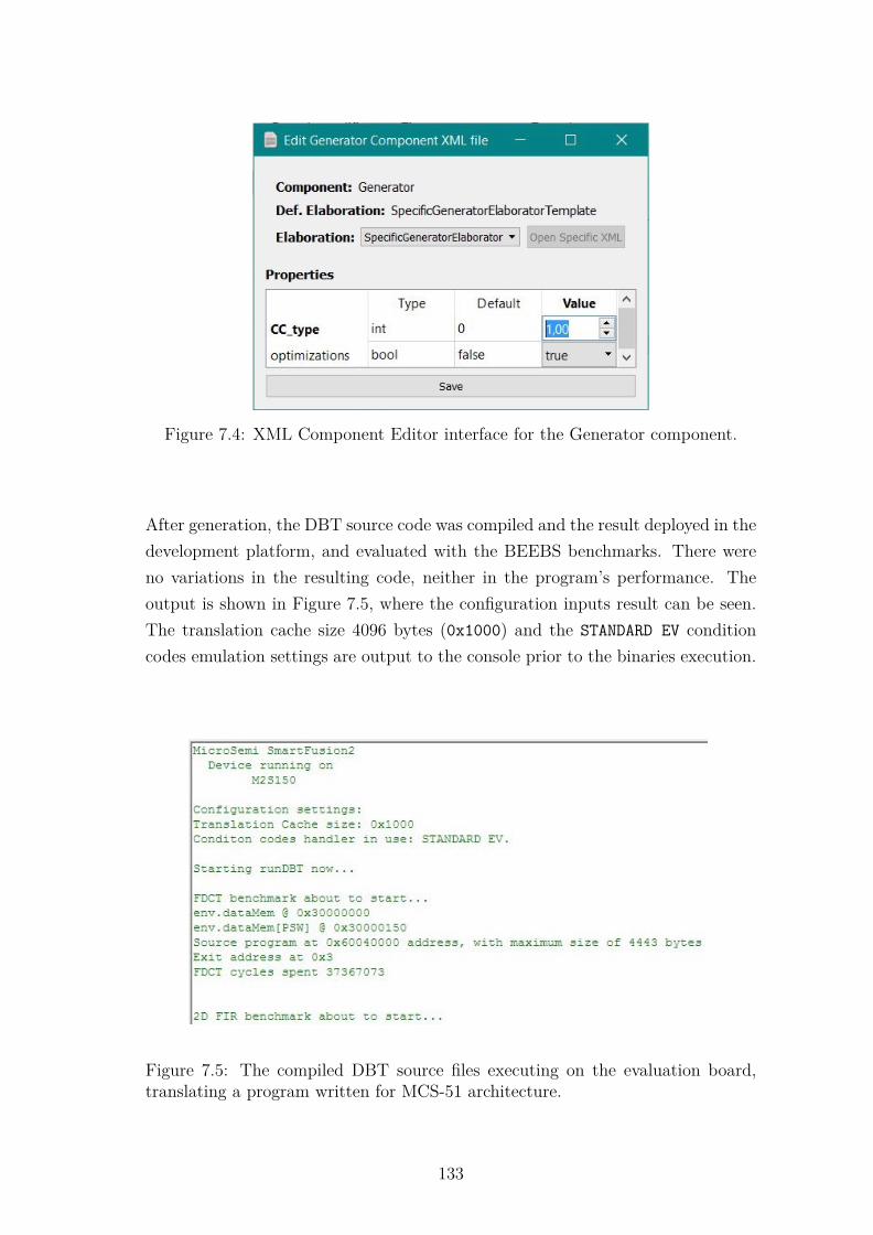
Figure 7.4: XML Component Editor interface for the Generator component.
After generation, the DBT source code was compiled and the result deployed in thedevelopment platform, and evaluated with the BEEBS benchmarks. There wereno variations in the resulting code, neither in the program’s performance. Theoutput is shown in Figure 7.5, where the configuration inputs result can be seen.The translation cache size 4096 bytes (0x1000) and the STANDARD EV conditioncodes emulation settings are output to the console prior to the binaries execution.
Figure 7.5: The compiled DBT source files executing on the evaluation board,translating a program written for MCS-51 architecture.
133

7.7 Conclusion
This chapter presented the FAT-DBT framework, the result of a modeling DSLfor DBT architectures targeted for in embedded systems. The developed DSL,supported by the composite pattern, was used to modeled a DBTor, creating ahigher abstraction level for system description. The attained functionality demon-strate that despite a DSL being hard to create, its potential contribution to themodeling, configuration and code generation of a certain domain tend to pay off,achieving higher productivity, lower development time and ease of use.
The proposed framework, FAT-DBT, aims to aid design automation, decreasingconfiguration efforts and promoting the use of DBT technology in the industryas a ready-to-use solution. The developed DBTor was modeled using the EL andintegrated in the FAT-DBT, from where it is possible to be configure throughthe GUI XML Component Editor interface at two levels, (1) at data supportcomponents size (e.g., TCache size) and (2) at a functional level, through thecustomization of different functional mechanism, like the CC emulation method.The framework provides the configured translator’s end source files without manualintervention on the DBTor’s source code and without any code overhead.
134
Chapter 8
Conclusions and Future Work
This thesis proposed a specialized DBT engine for legacy support of resource-constrained embedded devices. The presented solution integrates customizationfeatures, resourceability and retargetability characteristics, for ease of configura-tion and porting. A hybrid DBT architecture solution was explored by resourcingavailable hardware and FPGA fabric for overhead mitigation and functionalitiessupport. The final solution was integrated on a complete framework for ready-to-use DBT solutions.
This chapter concludes this thesis, discussing in Section 8.1 the answers to thepreviously posed research questions, and identifying in Section 8.2 the limitationsfound throughout the development of this work. Section 8.3 suggests future im-provements and points possible research directions and finally, Section 8.4 lists thepublications that resulted from the developed work.
8.1 Conclusions
Despite DBT appearance purpose being tightly connected with legacy supportand binary compatibility, it became widely adopted in the computer arena dueto its versatility and applicability in many other applications. The code instru-mentation and optimization opportunities that derived from its use, opened newpaths for software acceleration, system virtualization and simulation, among manyother applications. However, the use of DBT has associated overheads that resultfrom its deployment as an intermediary layer between the application binaries and
135

the execution machine. In order to benefit from the required DBT functionalities,while maintaining bearable amounts of overhead, software and hardware optimiza-tion techniques must be used. When considering resource-constrained embeddedsystems as the target machines for DBT, special attention should be dedicatednot only to address the overheads, but also to the limited resources that thesehost systems provide. An effective deployment requires a specially tailored andresource-aware DBT engine, capable of delivering the BT functionalities, whilemaintaining the overhead at tolerable levels. The support of legacy binaries inmodern resource-constrained embedded systems motivated the study of these is-sues, leading to the main research question raised in the Chapter 1 of this thesis:
How to leverage an optimized and accelerated dynamicbinary translator, targeting resource-constrained
embedded systems for legacy support?
The main question originated four different research directions, which were ad-dressed through the remaining seven chapters.
To answer to the first question, is DBT a possible solution to address thelegacy support challenges on the resource-constrained embedded sys-tems, an assessment of popular legacy and cost-efficient modern embedded archi-tectures was driven in Chapter 2. It lead to the selection of the Intel MCS-51 as agood legacy architecture example, while adopting the the ARMv7-M architectureas a deployment ISA, because of its reduced price, wide availability and popu-larity. During Chapter 3 and Chapter 4, an in-house DBT engine was developedfrom scratch because the state of the art failed in providing a cross-ISA DBT solu-tion portable to embedded systems. The DBTor was designed, implemented andinstantiated to the mentioned source and target architectures, tested and evalu-ated using the BEEBS benchmark suite. The results have shown that despite theexistence of considerable overheads, it is possible to attain similar or even fasterexecution of legacy binaries in a legacy support DBTor running in a low-end pro-cessor architecture. The DBT execution was characterized, and different overheadsources were identified, with particular emphasis on the CC emulation process.
The second research question’s intent was to identify how to attain a flexible,yet application-tailorable solution, while minimizing NRE developmentcosts and maximizing the solution applicability. This question was alsoaddressed in chapters 3 and 4, through the design of a architecturally agnosticDBTor with a resourceable and retargetable architecture. The use of an IR as a
136

source/target ISA abstraction layer and the deployment variability managementthrough OO-techniques allowed to minimize NRE efforts for multiple ISA portingsof the DBTor. Different Tcache management policies and sizes, as well as CCevaluation methods, were also easily integrated in the DBTor as customizationoptions.
To address the question on how to address the overheads associated withDBT, considering the low resources of the target devices, while provid-ing full legacy support, different software and hardware techniques were usedto address multiple sources of overhead. In Chapter 5, the CC emulation over-head was tackled through software-based LE, and a novel technique using COTShardware debug features. The innovative approach was evaluated against the LEand the standard evaluation, demonstrating its superiority on what concerns per-formance and functionality. Then, in Chapter 6, different hardware accelerationefforts were developed for overhead mitigation on Tcache management and CCshandling mechanisms. The hardware acceleration architecture’s versatility wasalso demonstrated by providing support to peripherals and interrupts emulation.The hybrid Tcache with hardware management achieved superior performancecompared to the software-only versions. On what concerns CC emulation, thehardware-based approach did not exceeded the debug monitor-based performance.However, it allowed to recover control over the debug functionalities of the tar-get processor that become unaccessible when using the debug hardware for CCevaluation. The peripheral and interrupt emulation support functionalities weretested with two UART transmission binaries, by polling and by interrupt. Theremapping of the peripheral was efficient enough to ensure accurate transmissionsat a baud-rate of 9600 bits per second.
Regarding the last question, how to manage system variability and enablesolution space exploration and automation, it was addressed in Chapter 7.To answer this question, a DSL for DBT architecture modeling was developed,creating a higher abstraction level for system description. Then, an embeddedsystems’ DBT architecture was described and a framework called FAT-DBT wasdesigned, providing DBT customization through a GUI for DBT design validation,system configuration and automatic code generation. FAT-DBT contributes todesign automation, decreasing configuration efforts and promoting the use of DBTtechnology in the industry as a ready-to-use solution.
137
8.2 Limitations
Several limitations were identified during the development of this solution, eitherbecause were intentionally left outside the scope of this thesis, or because werefound during its development. Such limitations are identified as:
• Energy consumption analysis and power optimization is a relevanttopic that was not addressed due to the already complex nature of the pro-posed research topic and the expected workload. However, and speciallyconsidering the type of systems addressed, energy consumption values willdepend on the host processor’s workload. Nonetheless, the energy consump-tion is expected to decrease with the improvement of the DBTor.
• Application level DBT was not explored and is not supported. This typeof translation would require an OS running in the host system, which wasleft out of the solution for resource-saving purposes. An additional cross-OS system-call conversion layer would also be necessary, introducing moreoverhead in the final system.
• Multi-thread and/or multi-core DBT approach is a limitation thatwould also require a host OS at the target system, and was not approached ei-ther. Despite the few task parallelism opportunities identified in the DBTor,multi-thread support could be used for speculative translation and othersystem management tasks, e.g., Tcache handling, peripherals and interruptpolling, among others.
• Real-time requirements would be extremely hard to obtain due to theDBT overheads and source/target clock domains’ disparity. This require-ment is rarely addressed in cross-ISA DBT, because the translation over-heads are very high, which difficult execution timing monitoring. Moreover,when using an IR-based DBTor, an one-to-multiple instruction translationis commonly used, which obfuscates the timing ratios of the source-to-targetinstructions matching.
• Manual decoding and porting of the IR for the source and target ISAs,respectively, despite functional, revealed to be a fastidious work and error-prone task. Although these options might have saved some time during theearly development of the DBTor, they are fully NRE and not reusable, and incase of a new source or target ISA porting, they would have to be repeated.
138
• Self-modifying code support features were not addressed. Although themechanisms to deal with it were available, since the source architecture doesnot allow its practice, it was not a concern during the deployment.
• BB chaining optimization is also a simple technique to implement, but dueto time constraints, it was not incorporated in the system.
• Cold code emulation was not included in the translator. This featuretakes advantage of the decoding effort of the instructions to quickly emulatetheir behavior during their first iteration. After a BB translation, the DBTengine does not require to switch to its execution, since it was emulatedalready. However, if the same BB is called again for execution, its cachedtranslation will be natively executed.
• Direct register mapping was also avoided for DBT portability reasons.This option harms the performance because replacing quick native registeroperations by load-store operations, will incur in a greater penalty.
• Timer peripherals pose some challenges on its support. The configurationsniffing and remapping of the source timers to target timers is supported,as long as the code to map the equivalent configurations is added to thetranslator. However, and due to differences of clock domains, performancepenalties and general de-synchronization between the native and translatedexecution environments, this topic requires further research in order to besupported.
8.3 Future Work
Despite the contributions this thesis provides to the state of the art, improvementsin terms of limitations and research guides are indicated as future work in thissection. The proposed tasks are presented as:
• Energy consumption profiling should be addressed in the future, mea-suring the power consumption data, and proceeding to its analysis, in orderto establish efficiency ratings for the different DBT components’ variations.
• Make the DBTor available as a service for OS integration. This sug-gestions targets not only the integrations of the DBT engine in a OS, asa binaries compatibility service, but also the re-design of the engine for a
139
multi-thread environment. This deployment might favor future optimizationtechniques exploration, e.g., speculative translation efforts, code optimiza-tions, and so on.
• Self-modifying code support features, previously addressed as a limita-tion, should be included and tested in the system. It is suggested a full cacheeviction strategy, when a write to the program memory is detected, in orderto avoid code coherency issues.
• BB chaining optimization, also mentioned in the Section Limitations, shouldalso be implemented in the system. This technique should provide consider-able performance gains, while having little impact on the deployment, sincea full eviction Tcache policy poses no coherency issues to BB chaining.
• Cold code emulation is another recommended feature to the DBTor. De-spite code translation being generally preferred over code emulation, the useof this technique during the decode stage should result in pure performancegains. This results from the capitalizing of great part of the decoding ef-fort, while avoiding Translation to Execution context switch and the nativeexecution of the BB’s first iteration.
• Direct register mapping technique should also be implemented, whilemaintaining portability flexibility. It is suggested the adoption of an adapt-able strategy that directly maps the source registers to the available targetmachine registers and allocates the remaining registers to memory locations.
• Automated ISA pairing tool for easy source and target portings of theDBTor, is a desirable feature to be included in the DBT framework. Thistool should address the NRE efforts minimization in three ways:
1. Source ISA to IR mapping. This feature’s goal is to achievean automated mapping of the source ISA to the IR micro operations. Thismight be achieved through a meta-representation of the ISAs instruction,for functionality, operands and operations identification and correspondencewith the IR’s micro operation. Although this feature would not dismisshuman intervention in the ISA’s meta-representation description, it wouldgreatly reduce the necessary knowledge of the ISA for new portings.
2. IR to target ISA porting. Similarly to the previous feature,this one should achieve an automated porting of the IR micro operations to
140

target machine code. This could be attained either by employing compilertechniques, like in QEMU, or through more advanced techniques, like theones resourcing the LLVM compiler infrastructure.
3. Automatic decoding generation. The goal of its implementationwould be to attain an automatic correspondence of the source ISA instruc-tions to the target machine code, combining the functionalities of 1. and2., into a decoding algorithm. The resulting algorithm, expressed as a C++method for post class integration, should explore advanced, yet efficient, de-coding methods. For instance, binary trees can be used to obtain efficientcode generation. The automatic decoding tool should also explore possi-ble direct source to target instruction correspondence, in order to avoid IRoverheads.
• Additional sources and target ISA support should be added to theFAT-DBT to test its portability and for enhanced application possibilities.MIPS architecture poses a good target candidate because of its regular ISA,while any of the legacy ISAs mentioned in Chapter 2 are possible sourcecandidates to be supported.
• Additional hardware support to assist and accelerated the DBTor shouldalso be explored. On a short term, it is suggested the full CC evaluation inhardware and a decoding algorithm porting to hardware. Nonetheless, manyother tasks are accountable for hardware offloading when FPGA fabric isavailable in the target device.
• FAT-DBT enhancement by improving the GUI to ease system configu-ration and reduce the number of code generation steps. The DSL semanticsshould also being improved, with the usage of semantic technology to de-scribe the domain knowledge. A semantically enhanced DSL will improvethe model validation and reduce the elaboration development efforts. Thiswill contribute to greater system scalability, configuration granularity, codegeneration efficiency and design verification.
141

8.4 List of Publications
The following publications resulted from the work developed in this thesis:
"A Dynamic Binary Translator Architecture for Resource-ConstrainedEmbedded Systems", F. Salgado, T. Gomes, J. Cabral and A. Tavares, [UNDERREVIEW] in IEEE Transactions on Computers.
"MODELA DBT: Model-Driven Elaboration Language Applied to Dy-namic Binary Translation", F. Salgado, A. Martins, D. Almeida, T. Gomes,J. L. Monteiro, and A. Tavares, in IECON 2017 - 43rd Annual Conference of theIEEE Industrial Electronics Society, Beijing, 2017.
"Condition Codes Evaluation on Dynamic Binary Translation for Em-bedded Platforms", F. Salgado, T. Gomes, S. Pinto, J. Cabral and A. Tavares,in IEEE Embedded Systems Letters, vol. 9, no. 3, pp. 89-92, Sept. 2017.
"Leveraging On-Chip Debug Features for Condition Codes Handlingin Dynamic Binary Translation", F. Salgado, J. Mendes, A. Tavares and M.Ekpanyapong, in 2012 Brazilian Symposium on Computing System Engineering,Natal, 2012.
"Shifting SOA to MPSoC: An exploratory example of application", F.Salgado et al., in Proceedings of 2012 IEEE 17th International Conference onEmerging Technologies & Factory Automation (ETFA 2012), Krakow, 2012, pp.1-4.
142
Bibliography
[1] Microsemi Corporation, “SmartFusion2 SoC FPGA Advanced Devel-opment Kit.” [Online]. Available: https://www.microsemi.com/products/fpga-soc/design-resources/dev-kits/smartfusion2/smartfusion2-advanced-development-kit, Date accessed September, 102017.
[2] Patterson, David, “The Future of Computer Architecture.” A white paperprepared for the Computing Community Consortium committee of the Com-puting Research Association, 2008.
[3] Intel Corporation, “Enabling consistent platform-level servicesfor tightly coupled accelerators.” Online, 2008. [Online]. Avail-able: https://www.intel.sg/content/dam/doc/white-paper/quickassist-technology-aal-white-paper.pdf, Date accessed Septem-ber, 1 2017.
[4] R. Obermaisser, H. Kopetz, and C. Paukovits, “A cross-domain multiproces-sor system-on-a-chip for embedded real-time systems,” IEEE Transactionson Industrial Informatics, vol. 6, no. 4, pp. 548–567, 2010.
[5] R. A. Klein and R. Moona, “Migrating software to hardware on FPGAs,”in Field-Programmable Technology, 2004. Proceedings. 2004 IEEE Interna-tional Conference on, pp. 217–224, IEEE, 2004.
[6] M. Oyamada, F. R. Wagner, M. Bonaciu, W. Cesario, and A. Jerraya,“Software performance estimation in MPSoC design,” in Proceedings of the2007 Asia and South Pacific Design Automation Conference, pp. 38–43,IEEE Computer Society, 2007.
143
[7] S. Sharma, C. Mukherjee, and A. Gambhir, “A Comparison of Network-on-chip and Buses,” in Proceedings of National Conference on Recent Advancesin Electronics and Communication Engineering (RACE-2014) (P. Kidwelly,ed.), pp. 28–29, 2014.
[8] P. Pampagnin, P. Moreau, R. Maurice, and D. Guihal, “Model driven hard-ware design: One step forward to cope with the aerospace industry needs,”in Specification, Verification and Design Languages, 2008. FDL 2008. Forumon, pp. 179–184, IEEE, 2008.
[9] M. Meier, M. Engel, M. Steinkamp, and O. Spinczyk, “LavA: An open plat-form for rapid prototyping of mpsocs,” in Field Programmable Logic andApplications (FPL), 2010 International Conference on, pp. 452–457, IEEE,2010.
[10] G. Savaton, J. Delatour, and K. Courtel, “Roll your own hardware descrip-tion language,” in OOPSLA & GPCE Workshop Best Practices for ModelDriven Software Development, 2004.
[11] X. Wang, S. X. Hu, E. Haq, and H. Garton, “Integrating legacy systemswithin the service-oriented architecture,” in Power Engineering Society Gen-eral Meeting, 2007. IEEE, pp. 1–7, IEEE, 2007.
[12] “STM32 32-bit ARM Cortex MCUs.” STM product web site, 2017.[Online]. Available: http://www.st.com/en/microcontrollers/stm32-32-bit-arm-cortex-mcus.html.
[13] X. Chen, Z. Zheng, L. Shen, W. Chen, and Z. Wang, “GSM: An Effi-cient Code Generation Algorithm for Dynamic Binary Translator,” 2011Fourth International Symposium on Parallel Architectures, Algorithms andProgramming, pp. 231–235, Dec. 2011.
[14] C. Cifuentes, M. Van Emmerik, N. Ramsey, and B. Lewis, “The Universityof Queensland Binary Translator (UQDBT) Framework,” The University ofQueensland, Sun Microsystems, Inc, 2001.
[15] V. Moya, “Study of the techniques for emulation programming,” Master’sthesis, Universidad Politécnica de Cataluña. España, 2001.
[16] R. Hookway and M. Herdeg, “Digital FX! 32: Combining emulation andbinary translation,” Digital Technical Journal, vol. 9, no. 1, pp. 3–12, 1997.
144

[17] H. Guan, B. Liu, T. Li, and A. Liang, “Multithreaded Optimizing Techniquefor Dynamic Binary Translator CrossBit,” 2008 International Conference onComputer Science and Software Engineering, pp. 945–952, 2008.
[18] L. Baraz, T. Devor, O. Etzion, S. Goldenberg, A. Skaletsky, Y. Wang, andY. Zemach, “IA-32 Execution Layer: a two-phase dynamic translator de-signed to support IA-32 applications on Itanium-based systems,” in Proceed-ings of the 36th annual IEEE/ACM International Symposium on Microar-chitecture, p. 191, IEEE Computer Society, 2003.
[19] J. Cui, J. Pang, Z. Shan, and X. Liu, “The multi-threaded optimizationof dynamic binary translation,” in Fuzzy Systems and Knowledge Discovery(FSKD), 2011 Eighth International Conference on, vol. 4, pp. 2432–2436,IEEE, 2011.
[20] K. K. Daniel J. Magenheimer, Arndt B. Bergh and J. A. Miller, “Hp 3000emulation on hp precision architecture computers,” HP Journal, pp. 87–89,12 1987.
[21] C. May, “Mimic: a fast system/370 simulator,” SIGPLAN ’87 Papers of theSymposium on Interpreters and interpretive techniques, vol. 22, no. 7, 1987.
[22] K. Andrews and D. Sand, “Migrating a CISC computer family onto RISC viaobject code translation,” ASPLOS V Proceedings of the fifth internationalconference on Architectural support for programming languages and operatingsystems, vol. 27, no. 9, pp. 213–222, 1992.
[23] R. L. Sites, A. Chernoff, M. B. Kirk, M. P. Marks, and S. G. Robinson,“Binary translation,” Communications of the ACM, vol. 36, no. 2, pp. 69–81, 1993.
[24] R. L. Sites, A. Chernoff, M. B. Kirk, M. P. Marks, and S. G. Robinson,“Binary translation,” Communications of the ACM, vol. 36, pp. 69–81, feb1993.
[25] B. Cmelik and D. Keppel, “Shade: A fast instruction-set simulator for ex-ecution profiling,” in Fast Simulation of Computer Architectures, pp. 5–46,Springer, 1995.
145
[26] Brethes, Mathieu, “Atome-Binary Translation for Accurate Simulation,”September 2004. [Online] Available: http://www8.cs.umu.se/education/examina/Rapporter/MathieuBrethes.pdf, Date accessed September 15th2017.
[27] J.-Y. Chen, W. Yang, T.-H. Hung, C. Su, and W. C. Hsu, “On static binarytranslation and optimization for arm based applications,” in Proceedings ofthe 6th Workshop on Optimizations for DSP and Embedded Systems, vol. 4,pp. 3–1, 2008.
[28] M. Chapman, D. Magenheimer, and P. Ranganathan, “MagiXen: Combiningbinary translation and virtualization,” Hewlett-Packard Development Com-pany, L.P. Approved, 2007.
[29] K. Adams and O. Agesen, “A comparison of software and hardware tech-niques for x86 virtualization,” Proceedings of the 12th international con-ference on Architectural support for programming languages and operatingsystems - ASPLOS-XII, p. 2, 2006.
[30] W. Chen, H. Lu, L. Shen, Z. Wang, and N. Xiao, “DBTIM: An AdvancedHardware Assisted Full Virtualization Architecture,” 2008 IEEE/IFIP Inter-national Conference on Embedded and Ubiquitous Computing, pp. 399–404,Dec. 2008.
[31] W. Chen, Z. Wang, H. Lu, L. Shen, N. Xiao, and Z. Zheng, “A HardwareApproach for Reducing Interpretation Overhead,” 2009 Ninth IEEE Inter-national Conference on Computer and Information Technology, pp. 98–103,2009.
[32] F. Xu, L. Shen, and Z. Wang, “A Dynamic Binary Translation FrameworkBased on Page Fault Mechanism in Linux Kernel,” in 2010 10th IEEE In-ternational Conference on Computer and Information Technology, pp. 2284–2289, IEEE, jun 2010.
[33] W. Chen, D. Chen, and Z. Wang, “An approach to minimizing the interpre-tation overhead in Dynamic Binary Translation,” The Journal of Supercom-puting, vol. 61, pp. 804–825, June 2011.
146
[34] N. Penneman, D. Kudinskas, A. Rawsthorne, B. De Sutter, and K. De Boss-chere, “Evaluation of dynamic binary translation techniques for full systemvirtualisation on armv7-a,” Journal of Systems Architecture, vol. 65, pp. 30–45, 2016.
[35] A. D’Antras, C. Gorgovan, J. Garside, J. Goodacre, and M. Luján,“HyperMAMBO-X64,” in Proceedings of the 13th ACM SIGPLAN/SIGOPSInternational Conference on Virtual Execution Environments - VEE ’17,pp. 228–241, ACM Press, 2017.
[36] W. Chen, H. Lu, L. Shen, Z. Wang, N. Xiao, and D. Chen, “A Novel Hard-ware Assisted Full Virtualization Technique,” 2008 The 9th InternationalConference for Young Computer Scientists, pp. 1292–1297, Nov. 2008.
[37] K. Ebcioglu and E. Altman, “DAISY: Dynamic compilation for 100% ar-chitectural compatibility,” ACM SIGARCH Computer Architecture News,1997.
[38] K. Ebcioglu, E. Altman, M. Gschwind, and S. Sathaye, “Dynamic binarytranslation and optimization,” IEEE Transactions on Computers, vol. 50,no. 6, pp. 529–548, 2001.
[39] Keppel, David, “Transmeta Crusoe Hardware, Software and Development.”AMAS-BT - Workshop on Architectural and Microarchitectural Supportfor Binary Translation, 2009. [Online]. Available: http://www.xsim.com/papers/crusoe-amasbt2009.pdf.
[40] Klaiber, Alexander, “The technology behind crusoe processors.” TransmetaTechnical Brief, 2000.
[41] Keppel, David, “Crusoe Processor Software Optimization Guide,” tech. rep.,Transmeta Corporation, 8 2001. Software Developer Bulletin.
[42] E. Altman, M. Gschwind, S. Sathaye, S. Kosonocky, A. Bright, J. Fritts,P. Ledak, D. Appenzeller, and Z. Filan, “Boa: The architecture of a binarytranslation processor,” IBM Research Report RC 21665, 2000.
[43] S. Sathaye, P. Ledak, J. LeBlanc, S. Kosonocky, M. Gschwind, J. Fritts,Z. Filan, A. Bright, D. Appenzeller, E. Altman, et al., “BOA: Targetingmulti-gigahertz with binary translation,” in Proc. of the 1999 Workshop onBinary Translation, pp. 2–11, sn, 1999.
147

[44] M. Gschwind, E. Altman, S. Sathaye, P. Ledak, and D. Appenzeller, “Dy-namic and transparent binary translation,” Computer, vol. 33, pp. 54–59,mar 2000.
[45] G. Ottoni, T. Hartin, C. Weaver, J. Brandt, B. Kuttanna, and H. Wang,“Harmonia,” in Proceedings of the 8th ACM International Conference onComputing Frontiers - CF ’11, p. 1, ACM Press, 2011.
[46] I. Böhm, T. J. Edler von Koch, S. C. Kyle, B. Franke, and N. Topham,“Generalized just-in-time trace compilation using a parallel task farm in adynamic binary translator,” PLDI ’11 Proceedings of the 32nd ACM SIG-PLAN Conference on Programming Language Design and Implementation,vol. 46, no. 6, pp. 74–85, 2011.
[47] K. Scott and J. Davidson, “Strata: A software dynamic translation infras-tructure,” Proceedings of the IEEE, pp. 1–10, 2001.
[48] K. Scott, N. Kumar, S. Velusamy, B. Childers, J. Davidson, and M. Soffa,“Retargetable and reconfigurable software dynamic translation,” Interna-tional Symposium on Code Generation and Optimization, 2003. CGO 2003.,pp. 36–47, 2003.
[49] D. L. Bruening, Efficient, Transparent, and Comprehensive Runtime CodeManipulation. PhD thesis, Department of Electrical Engineering and Com-puter Science, MIT, 2004. AAI0807735.
[50] B. Hawkins, B. Demsky, D. Bruening, and Q. Zhao, “Optimizing bi-nary translation of dynamically generated code,” Proceedings of the 2015IEEE/ACM International Symposium on Code Generation and Optimiza-tion, CGO 2015, pp. 68–78, 2015.
[51] S. Sridhar, J. S. Shapiro, E. Northup, and P. P. Bungale, “Hdtrans: an opensource, low-level dynamic instrumentation system,” in Proceedings of the2nd international conference on Virtual execution environments, pp. 175–185, ACM, 2006.
[52] S. Sridhar, J. S. Shapiro, and P. P. Bungale, “Hdtrans: a low-overheaddynamic translator,” ACM SIGARCH Computer Architecture News, vol. 35,no. 1, pp. 135–140, 2007.
148

[53] M. Payer and T. Gross, “Fast binary translation: Translation efficiency andruntime efficiency,” in 2st Workshop on Architectural and MicroarchitecturalSupport for Binary Translation, sn, 2009.
[54] M. Payer and T. R. Gross, “Generating low-overhead dynamic binary trans-lators,” Proceedings of the 3rd Annual Haifa Experimental Systems Confer-ence on - SYSTOR ’10, p. 1, 2010.
[55] J. D. Hiser, D. Williams, W. Hu, J. W. Davidson, J. Mars, and B. R.Childers, “Evaluating indirect branch handling mechanisms in software dy-namic translation systems,” in Proceedings of the International Symposiumon Code Generation and Optimization, CGO ’07, pp. 61–73, IEEE ComputerSociety, 2007.
[56] N. Kumar and B. Childers, “Flexible instrumentation for software dynamictranslation,” in Workshop on Exploring the Trace Space, 2003.
[57] N. Kumar, C. Bruce R., D. Williams, J. W. Davidson, and M. L. Soffa,“Compile-time planning for overhead reduction in software dynamic transla-tors,” International Journal of Parallel Programming, vol. 33, pp. 103–114,Jun 2005.
[58] K. Scott, N. Kumar, B. R. Childers, J. W. Davidson, and M. L. Soffa, “Over-head reduction techniques for software dynamic translation,” in 18th Inter-national Parallel and Distributed Processing Symposium, 2004. Proceedings.,pp. 200–, April 2004.
[59] J. a. Baiocchi, B. R. Childers, J. W. Davidson, and J. D. Hiser, “Reducingpressure in bounded DBT code caches,” in Proceedings of the 2008 inter-national conference on Compilers, architectures and synthesis for embeddedsystems - CASES ’08, p. 109, ACM Press, 2008.
[60] R. W. Moore, J. A. Baiocchi, B. R. Childers, J. W. Davidson, and J. D.Hiser, “Addressing the challenges of dbt for the arm architecture,” ACMSigplan Notices, vol. 44, no. 7, pp. 147–156, 2009.
[61] J. a. Baiocchi, B. R. Childers, J. W. Davidson, and J. D. Hiser, “Enablingdynamic binary translation in embedded systems with scratchpad memory,”ACM Transactions on Embedded Computing Systems, vol. 11, pp. 1–33, dec2012.
149

[62] C.-K. Luk, R. Cohn, R. Muth, H. Patil, A. Klauser, G. Lowney, S. Wallace,V. J. Reddi, and K. Hazelwood, “Pin: Building customized program analysistools with dynamic instrumentation,” SIGPLAN Not., vol. 40, pp. 190–200,June 2005.
[63] Q. Wu, M. Martonosi, D. W. Clark, V. J. Reddi, D. Connors, Y. Wu,J. Lee, and D. Brooks, “A dynamic compilation framework for controllingmicroprocessor energy and performance,” in Proceedings of the 38th annualIEEE/ACM International Symposium on Microarchitecture, pp. 271–282,IEEE Computer Society, 2005.
[64] K. Zhang, T. Zhang, and S. Pande, “Binary translation to improve energyefficiency through post-pass register re-allocation,” Proceedings of the fourthACM international conference on Embedded software - EMSOFT ’04, p. 74,2004.
[65] A. Schranzhofer, J.-J. Chen, and L. Thiele, “Dynamic power-aware mappingof applications onto heterogeneous mpsoc platforms,” IEEE Transactions onIndustrial Informatics, vol. 6, no. 4, pp. 692–707, 2010.
[66] D. Hong, C. Hsu, C. Chang, and J. Wu, “A Dynamic Binary TranslationSystem in a Client/Server Environment,” iis.sinica.edu.tw, 2012.
[67] L. Ling, C. Chao, S. Tingtao, L. Alei, and G. Haibing, “DistriBit: A Dis-tributed Dynamic Binary Execution Engine,” in 2009 Third Asia Interna-tional Conference on Modelling & Simulation, pp. 602–607, IEEE, 2009.
[68] H. Guan, Y. Yang, K. Chen, Y. Ge, L. Liu, and Y. Chen, “DistriBit,” inProceedings of the 19th ACM International Symposium on High PerformanceDistributed Computing - HPDC ’10, p. 684, ACM Press, 2010.
[69] W. Chen, L. Shen, H. Lu, Z. Wang, and N. Xiao, “A light-weight code cachedesign for dynamic binary translation,” Proceedings of the International Con-ference on Parallel and Distributed Systems - ICPADS, pp. 120–125, 2009.
[70] W. Zhang, B. Calder, and D. M. Tullsen, “An event-driven multithreadeddynamic optimization framework,” in Parallel Architectures and CompilationTechniques, 2005. PACT 2005. 14th International Conference on, pp. 87–98,IEEE, 2005.
150
[71] D. Ung and C. Cifuentes, “Optimising hot paths in a dynamic binary trans-lator,” ACM SIGARCH Computer Architecture News, vol. 29, pp. 55–65,Mar. 2001.
[72] H. Guan, E. Zhu, K. Chen, R. Ma, Y. He, H. Deng, and H. Yang, “ADynamic-Static Combined Code Layout Reorganization Approach for Dy-namic Binary Translation,” Journal of Software, vol. 6, pp. 2341–2349, Dec.2011.
[73] H. Guan, E. Zhu, H. Wang, R. Ma, Y. Yang, and B. Wang, “SINOF: Adynamic-static combined framework for dynamic binary translation,” Jour-nal of Systems Architecture, vol. 58, pp. 305–317, Sept. 2012.
[74] H. Guan, B. Liu, Z. Qi, Y. Yang, H. Yang, and A. Liang, “CoDBT: Amulti-source dynamic binary translator using hardware-software collabora-tive techniques,” Journal of Systems Architecture, vol. 56, pp. 500–508, oct2010.
[75] W. Hu, J. Wang, X. Gao, Y. Chen, Q. Liu, and G. Li, “Godson-3: A scalablemulticore RISC processor with x86 emulation,” IEEE micro, pp. 17–29, 2009.
[76] F. Vahid, G. Stitt, and R. Lysecky, “Warp Processing: Dynamic Translationof Binaries to FPGA Circuits,” Computer, vol. 41, pp. 40–46, jul 2008.
[77] R. a. Sokolov and a. V. Ermolovich, “Background optimization in full systembinary translation,” Programming and Computer Software, vol. 38, pp. 119–126, jun 2012.
[78] H. Guan, R. Ma, H. Yang, Y. Yang, L. Liu, and Y. Chen, “MTCrossBit: Adynamic binary translation system based on multithreaded optimization,”Science China Information Sciences, vol. 54, pp. 2064–2078, Sept. 2011.
[79] X. Tu, H. Jin, Z. Yu, J. Chen, and Y. Hu, “MT-BTRIMER: A Master-Slave Multi-threaded Dynamic Binary Translator,” 2010 Fifth InternationalConference on Frontier of Computer Science and Technology, pp. 51–56,Aug. 2010.
[80] C. Wang, V. Ying, and Y. Wu, “Supporting Legacy Binary Code in aSoftware Transaction Compiler with Dynamic Binary Translation and Opti-mization,” in Compiler Construction, vol. 4959 LNCS, pp. 291–306, SpringerBerlin Heidelberg, 2008.
151
[81] Y.-S. Hwang, T.-Y. Lin, and R.-G. Chang, “DisIRer: Converting a Retar-getable Compiler into a Multiplatform Binary Translator,” ACM Transac-tions on Architecture and Code Optimization, vol. 7, pp. 1–36, Dec. 2010.
[82] Probst, Mark, “Fast machine-adaptable dynamic binary translation,” Pro-ceedings of the Workshop on Binary Translation, pp. 1–7, 2001.
[83] M. Probst, a. Krall, and B. Scholz, “Register liveness analysis for optimizingdynamic binary translation,” Ninth Working Conference on Reverse Engi-neering, 2002. Proceedings., pp. 35–44, 2002.
[84] Probst, Mark, “Dynamic Binary Translator,” in UKUUG Linux Developers’Conference Linux 2002, 4-7 July 2002, Bristol, pp. 1–12, 2002.
[85] D. Ung and C. Cifuentes, “Machine-adaptable dynamic binary translation,”ACM SIGPLAN Notices, vol. 35, pp. 41–51, July 2000.
[86] Bellard, Fabrice, “QEMU, a Fast and Portable Dynamic Translator,” in Pro-ceedings of the Annual Conference on USENIX Annual Technical Conference,ATEC ’05, pp. 41–41, USENIX Association, 2005.
[87] X. Zhang, Q. Guo, Y. Chen, T. Chen, and W. Hu, “Hermes: A fast cross-ISA binary translator with post-optimization,” in 2015 IEEE/ACM Interna-tional Symposium on Code Generation and Optimization (CGO), pp. 246–256, IEEE, feb 2015.
[88] Y. Yindong, G. Haibing, and Z. Erzhou, “Crossbit: a multi-sources andmulti-targets DBT,” CLOUD COMPUTING 2010 : The First Interna-tional Conference on Cloud Computing, GRIDs, and Virtualization Cross-Bit:, pp. 41–47, 2010.
[89] B. Cabral, N. Cam, and J. Foran, “Accelerated volume rendering and tomo-graphic reconstruction using texture mapping hardware,” in Proceedings ofthe 1994 Symposium on Volume Visualization, VVS ’94, pp. 91–98, ACM,1994.
[90] Blank, Tom, “A survey of hardware accelerators used in computer-aideddesign,” IEEE Design Test of Computers, vol. 1, pp. 21–39, Aug 1984.
[91] A. R. Omondi and J. C. Rajapakse, FPGA implementations of neural net-works, vol. 365. Springer, 2006.
152

[92] T. Gomes, P. Garcia, S. Pinto, F. Salgado, J. Cabral, J. Monteiro, andA. Tavares, “Hardware-software extensions to a softcore processor for fpga-based adaptive pid control,” in Industrial Electronics (ISIE), 2013 IEEEInternational Symposium on, pp. 1–4, IEEE, 2013.
[93] P. Kinsman and N. Nicolici, “Dynamic binary translation to a reconfigurabletarget for on-the-fly acceleration,” Design Automation Conference (DAC),2011 48th ACM/EDAC/IEEE, pp. 286–287, 2011.
[94] W. Chen, Z. Wang, and D. Chen, “An emulator for executing IA-32 ap-plications on ARM-based systems,” Journal of Computers, vol. 5, no. 7,pp. 1133–1141, 2010.
[95] G. Kondoh and H. Komatsu, “Dynamic binary translation specialized forembedded systems,” Proceedings of the 6th ACM SIGPLAN/SIGOPS inter-national conference on Virtual execution environments - VEE ’10, p. 157,2010.
[96] M. Payer, B. Bluntschli, and T. R. Gross, “LLDSAL,” in Proceedings of theseventh workshop on Domain-Specific Aspect Languages - DSAL ’12, p. 15,ACM Press, 2012.
[97] S. Makarov, A. D. Brown, and A. Goel, “An Event-Based Language forDynamic Binary Translation Frame Works,” Proceedings of the 23rd Inter-national Conference on Parallel Architectures and Compilation, pp. 499–500,2014.
[98] J. Paredes, Dynamic binary translation for embedded systems with scratchpadmemory. PhD thesis, University of Pittsburgh, 2011.
[99] Y. Yao, Z. Lu, Q. Shi, and W. Chen, “FPGA based hardware-software co-designed dynamic binary translation system,” 2013 23rd International Con-ference on Field Programmable Logic and Applications, FPL 2013 - Proceed-ings. IEEE Computer Society., pp. 0–3, 2013.
[100] D. Richie and J. Ross, “Cycle-accurate 8080 emulation using an ARM11processor with dynamic binary translation,” in 2014 Twelfth ACM/IEEEConference on Formal Methods and Models for Codesign (MEMOCODE),pp. 186–189, IEEE, oct 2014.
153

[101] Intel Corp., “MCS-51 Microcontroller Family User’s Manual,” 1994. [On-lie] Available: http://www.keil.com/dd/docs/datashts/intel/ism51.pdf Date accessed September, 11 2017.
[102] Microchip, “8-bit PIC Microcontrollers,” 2002. Product page: http://www.microchip.com/design-centers/8-bit, Date accessed September, 112017.
[103] Motorola, “M68HC11 Reference Manual.” [Online]. Available: https://www.nxp.com/docs/en/reference-manual/M68HC11RM.pdf, Date accessedSeptember, 11 2017.
[104] Zilog, “Z80 Family Cpu User Manual,” 2002. User Manual UM008003-1202.
[105] ARM Limited, “ARM Architecture Thumb-2 Supplement,” 2005. ReferenceManual.
[106] ARM Limited, “ARM CoreSight Architecture Specification,” 2013.
[107] Atmel, “AVR Microcontrollers AVR Instruction Set Manual Table of Con-tents,” AVR Microcontrollers, 2016.
[108] Imagination Technologies, “MIPS Architecture For Programmers Volume I-B : Introduction to the microMIPS32 Architecture,” tech. rep., ImaginationTechnologies, 2011.
[109] EECatalog, “Engineers Guide to 8-Bit, 16-Bit & 32-Bit Technologies,” Em-bedded Systems Engineering, 2016.
[110] DOLPHIN Integration, “The future of the 8051 legacy upgraded for theInternet of Things ( IoT ),” Embedded Systems Engeneering, pp. 1–11, 2015.
[111] A. Limited, “ARM v7-M Architecture Reference Manual,” tech. rep., ARMLimited, 2010.
[112] ARM Limited, “Procedure call standard for the arm architecture,” Tech.Rep. ARM IHI 0042F, ARM Limited, 2015.
[113] Microsemi Corporation, “SmartFusion2 product page.” Microsemi web-site, 2017. [Online]. Available: https://www.microsemi.com/products/fpga-soc/soc-fpga/smartfusion2, Date accessed September 11th 2017.
154

[114] Microsemi Corporation, “SmartFusion2 Microcontroller Subsystem UserGuide.” User Guide, 2013.
[115] Microsemi Corporation, “Libero SoC v11.4 User’s Guide.” User Guide, 2012.
[116] J. Pallister, S. Hollis, and J. Bennett, “BEEBS: Open Benchmarks for EnergyMeasurements on Embedded Platforms.” Online: http://arxiv.org/abs/1308.5174, 2013.
[117] R. Guide and M. Architecture, “IAR C / C ++ Compiler Reference Guidefor the 8051 Microcontroller Architecture,” tech. rep., IAR Systems, 2011.
[118] H. Guan, H. Yang, Z. Qi, Y. Yang, and B. Liu, “The Optimizations in Dy-namic Binary Translation,” 2010 Proceedings of the 5th International Con-ference on Ubiquitous Information Technologies and Applications, pp. 1–6,Dec. 2010.
[119] N. Cardoso, Middleware e ferramentas para desenvolvimento de sistemas devigilância para segurança, controlo e conforto (SVSC 2-M Toolkit). PhDthesis, Universidade do Minho Escola, 2013.
[120] D. F. Bacon and P. F. Sweeney, “Fast static analysis of c++ virtual functioncalls,” SIGPLAN Not., vol. 31, pp. 324–341, Oct. 1996.
[121] M. F. Fernandez, “Simple and effective link-time optimization of modula-3programs,” in PLDI ’95 Proceedings of the ACM SIGPLAN 1995 conferenceon Programming language design and implementation, vol. 30, ACM, 1995.
[122] D. F. Bacon and P. F. Sweeney, “Fast static analysis of c++ virtual functioncalls,” ACM Sigplan Notices, vol. 31, no. 10, pp. 324–341, 1996.
[123] Troy D. Hanson, Arthur O’Dwyer, “Uthash, A hash table for C structures.”[Online]. Available: https://troydhanson.github.io/uthash/, Date ac-cessed July, 30 2017.
[124] C. Chao, Z. Yuyu, G. Haibing, and L. Alei, “A Two-Phase OptimizationApproach for Condition Codes in a Machine Adaptable Dynamic BinaryTranslator,” 2009 WRI World Congress on Computer Science and Informa-tion Engineering, pp. 29–32, 2009.
[125] Philips Semiconductors, “80C51 family programmer s guide and instructionset,” tech. rep., Philips Semiconductors, 1997.
155

[126] Microchip Technology, “PICmicro Mid-Range MCU Family Reference Ma-nual,” Tech. Rep. December 1997, Microchip, Inc., 1997.
[127] E. Borin and Y. Wu, “Characterization of dbt overhead,” in WorkloadCharacterization, 2009. IISWC 2009. IEEE International Symposium on,pp. 178–187, IEEE, 2009.
[128] T. Gomes, P. Garcia, F. Salgado, J. Monteiro, M. Ekpanyapong, andA. Tavares, “Task-Aware Interrupt Controller: Priority Space Unificationin Real-Time Systems,” IEEE Embedded Systems Letters, vol. 7, pp. 27–30,mar 2015.
[129] T. Gomes, P. Garcia, S. Pinto, J. Monteiro, and A. Tavares, “Bringing Hard-ware Multithreading to the Real-Time Domain,” IEEE Embedded SystemsLetters, vol. 8, pp. 2–5, mar 2016.
[130] R. Domínguez, D. Schaa, and D. Kaeli, “Caracal : Dynamic Translation ofRuntime Environments for GPUs.” AMAS-BT 2011 - AMAS-BT: 4th Work-shop on Architectural and Microarchitectural Support for Binary Transla-tion, 2011.
[131] A. C. S. Beck, M. B. Rutzig, G. Gaydadjiev, and L. Carro, “Transparentreconfigurable acceleration for heterogeneous embedded applications,” Pro-ceedings -Design, Automation and Test in Europe, DATE, pp. 1208–1213,2008.
[132] H.-S. Kim and J. Smith, “Hardware support for control transfers in codecaches,” in 22nd Digital Avionics Systems Conference. Proceedings (Cat.No.03CH37449), pp. 253–264, IEEE Comput. Soc, 2003.
[133] K. Hazelwood and R. Cohn, “A Cross-Architectural Interface for Code CacheManipulation,” in International Symposium on Code Generation and Opti-mization (CGO’06), pp. 17–27, IEEE, 2006.
[134] F. Salgado, “M2µP (multithreading microprocessor) memory hierarchies im-plementation,” Master’s thesis, Universidade do Minho/Asian Institute ofTechnology, Portugal/Thailand, 5 2011.
[135] ARM Limited, “Amba 3 ahb-lite protocol specification,” Tech. Rep. ARMIHI 0033A, ARM Limited, 2006. http://www.arm.com.
156
[136] N. Cardoso, P. Rodrigues, J. Vale, P. Garcia, P. Cardoso, J. Monteiro,J. Cabral, J. Mendes, M. Ekpanyapong, and A. Tavares, “A generative-oriented model-driven design environment for customizable video surveil-lance systems,” EURASIP Journal on Embedded Systems, vol. 2012, p. 7,dec 2012.
[137] ARM and Qualcomm Technologies, Inc., “Enabling the Next Mobile Com-puting Revolution with Highly Integrated ARMv8-A based SoCs,” tech. rep.,Qualcomm Technologies, Inc., 2014.
[138] Bettini, Lorenzo, Implementing Domain-Specific Languages with Xtext andXtend. Packt Publishing, 2013.
[139] Voelter, Markus, DSL Engineering - Designing, Implementing and UsingDomain-Specific Languages. CreateSpace Independent Publishing Platform,2010-2013.
[140] Fowler, Martin, Domain Specific Languages. Addison-Wesley Professional,1st ed., 2010.
[141] Czarnecki, Krzysztof, “Overview of Generative Software Development,”in Unconventional Programming Paradigms: International Workshop UPP2004, Le Mont Saint Michel, France, September 15-17, 2004, Revised Se-lected and Invited Papers (J.-P. Banâtre, P. Fradet, J.-L. Giavitto, andO. Michel, eds.), pp. 326–341, Springer Berlin Heidelberg, 2005.
[142] M. V. Thomas Stahl, Model-Driven Software Development. John Wiley &Sons, Ltd, 2006.
[143] J.-P. Tolvanen and M. Rossi, “MetaEdit+: Defining and Using Domain-specific Modeling Languages and Code Generators,” in Companion of the18th Annual ACM SIGPLAN Conference on Object-oriented Programming,Systems, Languages, and Applications, OOPSLA ’03, pp. 92–93, ACM, 2003.
[144] J. Marino and M. Rowley, Understanding SCA (Service Component Archi-tecture). Independent Technology Guides, Pearson Education, 2009.
[145] H. Behrens, M. Clay, S. Efftinge, M. Eysholdt, P. Friese, J. Köhn-lein, K. Wannheden, and S. Zarnekow, “Xtext User Guide.” http://www.eclipse.org/Xtext/documentation/1_0_1/xtext.pdf, 2010. Accessed:2017-03-11.
157

[146] Eclipse.org, “Xtext - Language Engineering Made Easy!.” [Online] Available:https://www.eclipse.org/Xtext/, Date accessed November, 3 2017.
[147] Eclipse.org, “Xtend Introduction.” [Online] Available: http://www.eclipse.org/xtend/documentation/, Date accessed November, 3 2017.
158