Jwaala Stotram Alm 27 Shlf 3 6084 1748 K Devanagari - Stotra

Background Statement for SEMI Draft Document 6084
Revision to SEMI C93-0216 (Preliminary)
GUIDE FOR DETERMINING THE QUALITY OF ION EXCHANGE RESIN USED IN POLISH APPLICATIONS OF ULTRAPURE WATER SYSTEM
Notice: This background statement is not part of the balloted item. It is provided solely to assist the recipient in reaching an informed decision based on the rationale of the activity that preceded the creation of this document.
Notice: Recipients of this document are invited to submit, with their comments, notification of any relevant patented technology or copyrighted items of which they are aware and to provide supporting documentation. In this context, “patented technology” is defined as technology for which a patent has issued or has been applied for. In the latter case, only publicly available information on the contents of the patent application is to be provided.
This is a first revision of C93-0216 which was published as a SEMI Preliminary standard in February 2016. This revision removes its Preliminary status.
The Liquid Chemicals NA TC Chapter reviewed C93-0216 (Preliminary) and recommended to issue a revision ballot, #6084.
Review and Adjudication Information
Task Force Review Committee Adjudication
Group: UPW Liquid Chemicals TC Chapter
Date: Monday, November 7, 2016 Tuesday, November 8, 2016
Time & Time Zone: 08:00 AM to 11:00 AM PST 3:00 PM to 6:00 PM PST
Location: SEMI HQ SEMI HQ
City, State/Country: San Jose, CA/USA San Jose, CA/USA
Leader(s)/Authors: Slava Libman (Air-Liquide) Frank Flowers (PeroxyChem)
Standards Staff: Inna Skvortsova ([email protected])
Inna Skvortsova ([email protected])

DRAFT
Document Number:
Meeting details are subject to change, and additional review sessions may be scheduled if necessary. Contact Standards staff for more information.
Telephone and web information will be distributed to interested parties as the meeting date approaches. If you will not be able to attend these meetings in person but would like to participate by telephone/web, please contact Standards staff.
Check www.semi.org/standards on calendar of event for the latest meeting schedule.
This is a Draft Document of the SEMI International Standards program. No material on this page is to be construed as an official or adopted Standard or Safety Guideline. Permission is granted to reproduce and/or distribute this document, in whole or in part, only within the scope of SEMI International Standards committee (document development) activity. All other reproduction and/or distribution without the prior written consent of SEMI is prohibited.
Page 1 Doc. jn l SEMI
Semiconductor Equipment and Materials International
3081 Zanker Road
San Jose, CA 95134-2127
Phone: 408.943.6900, Fax: 408.943.7943
DRAFT
Document Number:
SEMI Draft Document 6084
Revision to SEMI C93-0216 (Preliminary)
GUIDE FOR DETERMINING THE QUALITY OF ION EXCHANGE RESIN USED IN POLISH APPLICATIONS OF ULTRAPURE WATER SYSTEM
This Standard was technically approved by the Liquid Chemicals Global Technical Committee. This edition was approved for publication by the global Audits and Reviews Subcommittee on February 1, 2016. Available at www.semiviews.org and www.semi.org in February 2016.
1 Purpose
1.1 This Document describes a Guide for analysis of virgin high-purity ion exchange (HPIX) resin suitable for use in ultrapure water (UPW) polish applications. Further information regarding UPW systems can be found in SEMI F61.
1.2 The Guide focuses on analysis of HPIX resin used in UPW. This Document recommends parameters and test conditions that will minimize the effect of contamination from the resin on the manufacturing process.
1.3 The purpose of the Guide is to avoid prolonged rinse-up of the new HPIX when it is loaded into ion exchange (polish) tanks. The Guide results should be representative of full-scale applications.
2 Scope
2.1 This Document includes recommendations for virgin HPIX resin sample handling and test conditions.
2.2 The Document provides an example of the performance of state-of-the-art resins; the data was obtained following this Guide. However the quality criteria are expected to be determined by the end user based on the user-specific needs.
2.3 It is the intent of this Guide to focus on virgin HPIX resin. The quality parameters assessed, as recommended by this Guide, include quantitative measures of particle contribution, metallic contribution, organics contribution, residue after evaporation (RAE) (nonvolatile residue [NVR]), and broken beads content.
2.4 The Guide takes the wetted-stream performance of virgin HPIX resin into consideration and reflects the current manufacturing processes of the resin manufacturers.
2.5 Leach-out procedures referenced within this Document provide values for both static and dynamic conditions. Although the static leach-out testing is sufficient to determine resin quality, the end user should decide whether to use a dynamic leach-out testing; dynamic testing provides conditions closer to mimicking the actual mixed-bed operation. Choosing either a dynamic leach test or a static leach test is determined by the end user needs. Dynamic leach tests should be used to estimate the rinse-up flush volume. Static leach tests should be used for quality assurance when baseline virgin resin quality has already been established (otherwise use the dynamic leach test to estimate the rinse-up time).
2.6 Only mixed virgin HPIX resin is used for the testing within this Document. When the resin is supplied in nonmixed form (i.e., anionic and cationic), a mixed sample is used for analysis.
This is a Draft Document of the SEMI International Standards program. No material on this page is to be construed as an official or adopted Standard or Safety Guideline. Permission is granted to reproduce and/or distribute this document, in whole or in part, only within the scope of SEMI International Standards committee (document development) activity. All other reproduction and/or distribution without the prior written consent of SEMI is prohibited.
Page 2 Doc. jn l SEMI
Semiconductor Equipment and Materials International
3081 Zanker Road
San Jose, CA 95134-2127
Phone: 408.943.6900, Fax: 408.943.7943
DRAFT
Document Number:
2.7 The Guide assumes that the virgin HPIX resin tested is representative of the virgin HPIX resin to be loaded in the mixed-beds tanks. The resin shelf life, storage, and delivery conditions should be taken into account when planning the testing.
2.8 This Guide applies to virgin HPIX resin as well as point of use (POU) HPIX modules intended for use in semiconductor manufacturing equipment and their ancillary equipment.
2.9 This Guide includes recommended analytical testing that the end user can perform; the end user should determine which analyses are required and whether to conduct optional testing.
NOTICE: SEMI Standards and Safety Guidelines do not purport to address all safety issues associated with their use. It is the responsibility of the users of the Documents to establish appropriate safety and health practices, and determine the applicability of regulatory or other limitations prior to use.
3 Limitations
3.1 This Guide applies solely to virgin HPIX resin testing. Quality and performance of the associated equipment (i.e., HPIX beds, piping, piping components) are not included in the Guide.
3.2 Virgin HPIX resin tested by following this Guide is intended for use in the polishing system of (UPW) systems only (i.e., located downstream the UPW tank). These testing conditions may exceed the needs of resin used in primary mixed beds and other less critical applications.
3.3 The Guide is designed to assess contamination from the resin in an ‘as-received’ state; onsite resin handling may add contaminants. The effects of the onsite handling are beyond the scope of this Document, but should be considered by the supplier or user.
3.4 Performance of premixed resin vs. mixed in the lab is expected to be different. The sample should be prepared (i.e., mixed) in the same way it is done for the actual application (premixed by manufacturer vs. mixed onsite).
3.5 This Guide is not intended to supersede customer specifications.
3.6 Virgin HPIX resin samples tested under the conditions recommended by this Guide may vary in their performance from the resin used in the actual UPW system. Resin inconsistency should be addressed with the resin supplier or by conducting a statistical analysis of the resin quality data.
3.7 The accuracy of the data generated by this Guide is limited to the accuracy of the analytical techniques used to measure resin quality.
3.8 Tolerances in the figures used in the Guide (such as flow rate, concentration, etc.) are ±10% unless otherwise stated.
3.9 This Guide application is limited to the ambient temperature UPW system. Other applications, such as hot UPW systems or different treatment solvent have not been considered in this Document.
3.10 The reference data provided in Appendix 2 is representative for 2014 state-of-the-art resin quality and may not be fully representative for future state-of-the-art resin.
3.11 Limited experience and data are currently available in application of this Guide. Additional reproducibility studies may need to be conducted by the end user when defining performance criteria for the resin tested.
3.12 This Guide recommends a simplified option of the static leach test vs. dynamic leach test, mimicking actual polish mixed operation. Although data in Appendix 2 suggested that static leach test may be representative for the analysis of the resin performance under dynamic conditions, the choice of the testing should take into account the fact of the limited amount of data collected by the date of publication of this Document.
This is a Draft Document of the SEMI International Standards program. No material on this page is to be construed as an official or adopted Standard or Safety Guideline. Permission is granted to reproduce and/or distribute this document, in whole or in part, only within the scope of SEMI International Standards committee (document development) activity. All other reproduction and/or distribution without the prior written consent of SEMI is prohibited.
Page 3 Doc. jn l SEMI
Semiconductor Equipment and Materials International
3081 Zanker Road
San Jose, CA 95134-2127
Phone: 408.943.6900, Fax: 408.943.7943

DRAFT
Document Number:
4 Referenced Documents
4.1 SEMI Standards and Safety Guidelines
SEMI E49 — Guide for High Purity and Ultrahigh Purity Piping Performance, Subassemblies, and Final Assemblies
SEMI F40 — Practice For Preparing Liquid Chemical Distribution Components for Chemical Testing
SEMI F57 — Specification for Polymer Materials and Components Used in Ultrapure Water and Liquid Chemical Distribution Systems
SEMI F61 — Guide for Ultrapure Water Systems used in Semiconductor Processing
SEMI F63 — Guide for Ultrapure Water Used in Semiconductor Processing
SEMI F104 — Particle Test Method Guide for Evaluation of Components Used in Ultrapure Water and Liquid Chemical Distribution Systems
SEMI S2 — Environment, Health, and Safety Guideline for Semiconductor Manufacturing Equipment
4.2 ASTM Standards1
ASTM D4779 — Standard Test Method for Total, Organic, and Inorganic Carbon in High Purity Water by Ultraviolet (UV) or Persulfate Oxidation, or Both, and Infrared Detection (Withdrawn 2002)
ASTM D5544 — Standard Test Method for On-line Measurement of Residue After Evaporation of High-Purity Water
ASTM D5904 — Standard Test Method of Total Carbon, Inorganic Carbon, and Organic Carbon in Water by Ultraviolet, Persulfate Oxidation and Membrane Conductivity Detection
4.3 ISO Standard2
4.4 ISO 14644-1 — Cleanrooms and Associated Controlled Environments – Part 1: Classification of Air Cleanliness by Particle Concentration
4.5 Federal Standard3
FED STD 209E — Airborne Particulate Cleanliness Classes in Cleanrooms and Clean Zones
4.6 Other Documents
International Technology Roadmap for Semiconductors (ITRS)4
NOTICE: Unless otherwise indicated, all documents cited shall be the latest published versions.
5 Units
5.1 Parts per million (ppm) is equivalent to µg/mL or mg/L, where 1 L approximately equals 1 kg.
5.2 Parts per billion (ppb) is equivalent to ng/mL or µg/L, where 1 L approximately equals 1 kg.
5.3 Parts per trillion (ppt) is equivalent to pg/mL or ng/L, where 1 L approximately equals 1 kg.
1 ASTM International, 100 Barr Harbor Drive, West Conshohocken, PA 19428-2959, USA; Telephone: +1.610.832.9585, Fax: +1.610.832.9555, http://www.astm.org2 International Organization for Standardization, ISO Central Secretariat, 1, ch. de la Voie-Creuse, CP 56, CH-1211 Geneva 20, Switzerland; Telephone: +41.22.749.01.11, Fax: +41.22.733.34.30, http://www.iso.org3 U.S. General Services Administration, 1800 F Street, NW, Washington DC 20405, USA; Telephone: +1.800.488.3111, http://www.gsa.gov4 International Technology Roadmap for Semiconductors; http://www.itrs2.net/This is a Draft Document of the SEMI International Standards program. No material on this page is to be construed as an official or adopted Standard or Safety Guideline. Permission is granted to reproduce and/or distribute this document, in whole or in part, only within the scope of SEMI International Standards committee (document development) activity. All other reproduction and/or distribution without the prior written consent of SEMI is prohibited.
Page 4 Doc. jn l SEMI
Semiconductor Equipment and Materials International
3081 Zanker Road
San Jose, CA 95134-2127
Phone: 408.943.6900, Fax: 408.943.7943

DRAFT
Document Number:
5.4 Micrometer is a unit of length equal to one millionth of a meter, or one thousandth of a millimeter.
6 Terminology
1: General terms for UPW systems can be found in SEMI F61.
6.1 General terms and acronyms used in this Standard are listed below and may be defined in SEMI F61.
6.2 Abbreviations and Acronyms
6.2.1 DMA — differential mobility analyzer
6.2.2 HPIX — high-purity ion exchange
6.2.3 HPW — high purity water
6.2.4 ICP-MS — inductively coupled plasma mass spectrometry
6.2.5 ITRS — International Technology Roadmap For Semiconductors
6.2.6 LC-OCD — liquid chromatography with organic carbon detector
6.2.7 LNS — Liquid Nano-particle Sizing System; an example of a particle size distribution analyzer (PSDA) used for the validation testing, see results in Appendix 2.
6.2.8 LPC — laser particle counter
6.2.9 NRM — nonvolatile residue monitor
6.2.10 NVR — nonvolatile residue
6.2.10.1 Discussion — NVR is also called residue after evaporation (RAE).
6.2.11 PFA — perfluoroalkoxy
6.2.12 POU — point of use
6.2.13 PSDA — particle size distribution analyzer
6.2.14 PVDF — polyvinylidene fluoride
6.2.15 RAE — residue after evaporation
6.2.15.1 Discussion — RAE is also called nonvolatile residue (NVR).
6.2.16 SEM — scanning electron microscope
6.2.17 TOC — total organic carbon
6.2.18 UPW — ultrapure water
6.3 Definitions
6.3.1 background — the contaminant concentrations in the test system reported by analyzers, such as a particle size distribution analyzer (PSDA), nonvolatile residue monitor (NRM), total organic carbon (TOC), and others. Background includes contaminant contributions from the ultrapure water (UPW) and the test equipment components.
6.3.2 delta measurement — the ultrapure water (UPW) contaminant concentration difference between the inlet of the resin column and the outlet of the resin column.
This is a Draft Document of the SEMI International Standards program. No material on this page is to be construed as an official or adopted Standard or Safety Guideline. Permission is granted to reproduce and/or distribute this document, in whole or in part, only within the scope of SEMI International Standards committee (document development) activity. All other reproduction and/or distribution without the prior written consent of SEMI is prohibited.
Page 5 Doc. jn l SEMI
Semiconductor Equipment and Materials International
3081 Zanker Road
San Jose, CA 95134-2127
Phone: 408.943.6900, Fax: 408.943.7943

DRAFT
Document Number:
6.3.3 dynamic leach test skid — the system providing resin-evaluation test analysis. The test skid includes piping, resin column, flow meters, pressure gauges, valves, regulators, sample ports, etc. Figure 1 provides illustration of the skid.
6.3.4 virgin HPIX resin — an unused, high purity ion exchange (HPIX) resin that has not been regenerated.
7 Dynamic Leach Test Skid Configuration
7.1 The dynamic leach test skid should be made of high-purity components, meeting SEMI F57 quality requirements. Figure 1 presents the recommended configuration of the skid. The ion exchange column is made of polyvinylidene fluoride (PVDF) with perfluoroalkoxy (PFA) tubing connecting the column to the UPW system and analytical equipment.
U P W
U P W re tu rn o r d ra in
U P W
U P W re tu rn o r d ra in
V e n t tod ra in
V e n t tod ra in
N o n V o la tileR e sidu e m o n ito r
T o ta l O rga n icC a rb o n m o n ito r
U P W re tu rn o r d ra in
U P W re tu rn o r d ra in
P a rtic le S iz eD is tr ib u tio n
A n a ly z e rU P W re tu rn o r d ra in
L e n g th - 1 ,2 0 0 m m
In te rn a l D ia m e te r - 2 5 .4 m m
T o ta l e ff lu e n tf lo w ra te - 4 2 0 2 0 m L /m in
P 1P 2
+
T e m p
Figure 1General Test Schematic Diagram for Dynamic Leach Test
7.2 Minimum operating pressure should be sufficient to feed the instruments downstream of the ion exchange column, typically 25 psig (172 kPa). The pressure gauges and flow meters should be installed downstream or side stream to avoid contamination. Pressure on the feed side to the column should be 207 to 310 kPa (30 to 45 psig) to reduce potential micro bubble formation. The high-pressure limit depends upon the materials of construction (for safety and leak prevention).
This is a Draft Document of the SEMI International Standards program. No material on this page is to be construed as an official or adopted Standard or Safety Guideline. Permission is granted to reproduce and/or distribute this document, in whole or in part, only within the scope of SEMI International Standards committee (document development) activity. All other reproduction and/or distribution without the prior written consent of SEMI is prohibited.
Page 6 Doc. jn l SEMI
Semiconductor Equipment and Materials International
3081 Zanker Road
San Jose, CA 95134-2127
Phone: 408.943.6900, Fax: 408.943.7943

DRAFT
Document Number:
7.3 Ultrapure, low-particle, low-TOC, low-shedding piping systems should be used in all wetted flow paths from the UPW source to the dynamic leach test skid to ensure that adequate water quality is maintained. Consider the recommendations within SEMI E49 when designing and assembling the system.
7.4 Protect the test system from excessive vibration, which could lead to high particle-background counts.
7.5 Minimum operating pressure downstream of the dynamic leach test skid should be 138 kPa (20 psig) during testing to avoid gas bubbles.
7.6 The UPW should be in compliance with the following minimum guidelines:
7.6.1 Temperature — 23 ± 5°C (77 ± 9°F).
7.6.2 Resistivity — ≥18 MΩ·cm at 25°C (77°F).
7.6.3 TOC — <2 ppb.
7.6.4 NVR — <0.2 ppb.
7.6.5 Maximum Recommended Particle-Concentration Background Level — <1 particle/mL (≥0.05 µm). Background particle levels measured by PSDA are dictated by the resin performance expectations (see Figure A2-2, Appendix 2).
7.6.6 To ensure a stable background level, before beginning the test install and rinse the ion exchange column in an enclosed ISO Class 7 (per current revision of ISO 14644-1, roughly equivalent to FED STD 209E Class 10,000), or better, environment. Follow procedures necessary to maintain ISO Class 7, or better, when handling any part of the test system, or during the testing. End users requiring more exacting testing should consider following more stringent testing requirements.
7.6.7 Instrumentation, including flow meters, pressure gauges/transducers and temperature sensors, should be calibrated in accordance with the manufacturers’ procedures and frequency.
7.6.8 Bubbles cause metrology errors; orient the test column and the plumbing between the components under test to limit bubble entrapment. Position the ion exchange column vertically and vent the test skid to prevent gas accumulation and bubble formation. Provisions should be included in the test stand to capture and divert bubbles before they enter the instrumentation supply lines.
2: UPW flow through the ion exchange column should be from the top to the bottom to prevent resin separation.
8 Sample Recommendations
8.1 Test a representative ion exchange virgin resin sample from the batch under consideration.
8.2 To take a virgin resin sample from the drums at the end user location, it is recommended to follow this procedure:
8.2.1 Avoid construction and other maintenance activities in the area where the sample is taken.
8.2.2 Rinse the outside of the drums with high purity water (HPW) before opening to remove contamination collected during transport and storage. Allow the water to drip off the drums.
8.2.3 Don clean room suit and low-zinc gloves.
8.2.4 Prepare clean bags for the resin sampling and shipping. Use double-bagged packaging (the inner bags should be qualified for low background level of particles, while the outer bags should have low gas permeability).
8.2.5 Take resin from a previously unopened drum.This is a Draft Document of the SEMI International Standards program. No material on this page is to be construed as an official or adopted Standard or Safety Guideline. Permission is granted to reproduce and/or distribute this document, in whole or in part, only within the scope of SEMI International Standards committee (document development) activity. All other reproduction and/or distribution without the prior written consent of SEMI is prohibited.
Page 7 Doc. jn l SEMI
Semiconductor Equipment and Materials International
3081 Zanker Road
San Jose, CA 95134-2127
Phone: 408.943.6900, Fax: 408.943.7943

DRAFT
Document Number:
8.2.6 Open a representative drum and open the protective bags inside the drum.
8.2.6.1 If resin prepared for testing is supplied from different batches or was stored under different conditions, you may need to test more than one sample.
8.2.6.2 If the amount of resin in a single drum is <10% of the total amount of the resin to be used, you may need to sample more than one drum in order to obtain representative results.
8.2.7 Sample resin immediately after you open the drum.
8.2.7.1 Take the sample from the top of the drum to prevent excess liquid from being taken with the sample.
8.2.7.2 Remove approximately 5 cm (2 in.) of the upper resin layer.
8.2.7.3 Take 1 L of the resin sample for a static leach test and 1 L for a dynamic leach test.
8.2.7.4 Minimize exposure of the resin sample to ambient contamination.
8.2.7.5 Use gentle motion to avoid damaging the resin beads.
8.3 Place the resin in a prepared clean bag and seal the bag.
8.4 Wrap the resin sample in bubble wrap to protect it during shipping.
8.5 Place the resin sample in a cooler and ship to the lab using fast, direct delivery (do not exceed one week in shipment). Add ‘FRAGILE’ sticker.
3: Resin sample handling and packaging may impact the test results. Samples submitted for testing should reflect standard practices of handling and packaging by the resin manufacturer in accordance with the typical manufacturing processes.
9 Test Methodology
9.1 Leach-Out Parameters
9.1.1 This Document does not provide specific quality requirements for leachable parameters. The end user should define quality requirements based upon the process-specific sensitivity to contamination, the ion exchange polish system design, and the data provided in Appendix 2. The results in Appendix 2 are based on the benchmarking study and indicate the actual range of performance of typical resins used in ion exchange polish applications.
9.1.2 Success criteria considerations for TOC and particle release. Contamination by organic compounds causes silicon oxidation. It also affects etching uniformity, wafer and mask cleaning, adhesion of the resist, gate oxide breakdown voltage, epitaxial growth, atomic layer deposition (ALD), and chemical vapor deposition (CVD) of silicon nitride or other thin film deposition.
9.1.2.1 Loading virgin HPIX resin for applications with tight target levels for TOC and particles poses risk to the final UPW quality.
9.1.2.1.1 In a high volume manufacturing (HVM) facility where a number of parallel polish mixed beds are used, TOC contribution of less than 0.3 ppb is considered insignificant if the resin is replaced in only one of the parallel polish tanks. The UPW from additional tanks dilutes the TOC from the tank with new virgin resin.
9.1.3 Critical particle size is specific to the end user’s manufacturing process and technology. Particles released by the virgin HPIX resin can contaminate devices and critical surfaces as well as disrupt the photolithography process, thereby decreasing yields.
9.1.4 Based upon the UPW particle concentration target (in particles per liter) and the assumption that the final filter should provide some particle retention, the end user should estimate the acceptable particle concentration for the This is a Draft Document of the SEMI International Standards program. No material on this page is to be construed as an official or adopted Standard or Safety Guideline. Permission is granted to reproduce and/or distribute this document, in whole or in part, only within the scope of SEMI International Standards committee (document development) activity. All other reproduction and/or distribution without the prior written consent of SEMI is prohibited.
Page 8 Doc. jn l SEMI
Semiconductor Equipment and Materials International
3081 Zanker Road
San Jose, CA 95134-2127
Phone: 408.943.6900, Fax: 408.943.7943

DRAFT
Document Number:
polish tank effluent. If the resin change-out is spread over a year particle leach out from additional tanks dilutes the particle concentration from the tank being measured.
9.1.5 Metal leach consideration also depends upon the end user metal specifications. Metallic contamination can alter the electrical properties of microelectronic devices and corrode or etch microelectronic devices and critical surfaces during fabrication, causing immediate or future device failure.
9.1.6 For high purity applications susceptible to metals contamination, the end user should conduct an HCl leach using quality criteria based on Appendix 2 ‘best in class’ performance. For less critical applications, it is recommended that UPW extraction is used with all metals to be below the detection limits, as indicated in Appendix 2.
9.1.7 One week rinse time is considered the maximum acceptable time period based on the common industry practice.
4: Using the performance quality criteria, ‘best in class’ HPIX resin is recommended where tightest quality is required (per Appendix 2). Application of stringent requirements may affect schedule and cost.
5: Background is measured in the static leach test containers or when UPW flows through the dynamic leach test skid (after rinsed and cleaned components have reached a steady-state of background contamination).
6: Useful when the inlet analyte concentration is too unstable during the test period to allow the proper use of an average background measurement. Delta Measurement can be achieved by using two calibrated analyzers that have had their responses matched on the same water sample.
9.2 Other Parameters
9.2.1 The following recommendations are provided for estimating the whole-bead content.
7: If the virgin HPIX resin does not meet end user quality requirements, the end user should consult the resin supplier.
9.2.1.1 Whole bead content: the virgin ion exchange resin is considered acceptable for use in polish tanks if the resin contains >90% of whole and non-cracked beads and >95% of unbroken beads.
9.3 Particle Contribution Test
9.3.1 UPW is used for the particle contribution testing. The following instruments are employed:
9.3.1.1 In situ PSDA
9.3.1.2 In situ NRM (if most of the NVR = particles)
9.3.1.3 Grab sample LPC
9.3.1.4 Grab Sample PSDA
9.3.1.5 Grab Sample SEM
9.3.2 The Dynamic Leach Test evaluates particle contribution performance of the virgin ion exchange resin in a continuous flushing mode and provides an indication of the volume of UPW required to bring particle levels to meet the end user’s requirements.
9.4 Organic Contamination
9.4.1 The measurement of TOC is a common water quality screening method for organic materials; maximum TOC levels should be <0.5ppb but the actual effects of the individual compounds can depend on the structure of the molecules, and the semiconductor manufacturing processes. Any organic compound in UPW is a potential nutrient to increase bacterial growth. Methods other than measuring TOC, such as liquid chromatography with organic carbon detector (LC-OCD), may be needed to assess the identification of individual organic contaminants.This is a Draft Document of the SEMI International Standards program. No material on this page is to be construed as an official or adopted Standard or Safety Guideline. Permission is granted to reproduce and/or distribute this document, in whole or in part, only within the scope of SEMI International Standards committee (document development) activity. All other reproduction and/or distribution without the prior written consent of SEMI is prohibited.
Page 9 Doc. jn l SEMI
Semiconductor Equipment and Materials International
3081 Zanker Road
San Jose, CA 95134-2127
Phone: 408.943.6900, Fax: 408.943.7943

DRAFT
Document Number:
9.4.1.1 The TOC analyzer should correctly measure the organic Carbon contained in organic compounds that also include Nitrogen, Sulfur, Phosphorus, and Chlorine in their structures.
9.4.1.2 Use LC-OCD to identify either unusual organic compounds or those compounds that are present in unusually high concentrations. Refer to the example of an LC-OCD chromatogram shown in Appendix 2.
9.4.1.3 Use the static leach test to evaluate virgin ion exchange resin quality, using Appendix 2 data for reference.
9.4.1.4 Use the dynamic leach test to evaluate the TOC rinse-up volume, this is effective when done in conjunction with particle testing. If the source UPW TOC level fluctuates during the test period, a delta measurement between the column inlet and outlet for the TOC may be required.
9.4.2 The temperature of virgin ion exchange resin during a static leach test should be 40 ± 3°C. A temperature specification is used to achieve comparable data for ion exchange resin and components and is not indicative of service temperatures.
9.4.3 Report measured values of TOC in micrograms of contamination per liter of resin tested (µg/L). Detection limits (also defined in µg/L) should be reported for all measured values of TOC.
8: The static leach test using UPW, even one of a15-hour duration, has limitations. The values measured using a static leach test do not directly relate to the trace contaminant values which could be present in a flowing stream of liquid. Virgin ion exchange resin quality can be defined using the correlation studies for dynamic and static leach tests shown in Appendix 2.
9.4.4 Metallic Contamination Test
9.4.4.1 Metallic contamination specifications and testing may be needed for ion exchange virgin resin samples tested. It is particularly important for UPW applications where sensitivity to trace metals is high.
9.4.4.2 Virgin HPIX resin should conform to the end user’s specifications. In a UPW the static leach test, no metals should be detected in the leach solution. Refer to Appendix 2 for information on the metal extractable.
9.4.5 Use either UPW or acid for the static leach tests.
9.4.5.1 Use a static leach test with UPW for all semiconductor applications.
9.4.5.2 Use a static leach test with HCl for processes susceptible to metal contamination.
9.4.6 The temperature of virgin of ion exchange resin during a static leach test should be 40 ± 3°C for UPW and the ambient temperature (23 ± 2°C) for HCl. A temperature specification is used to achieve representative data for ion exchange resin and is not indicative of service temperatures.
9.4.7 Report measured values of metallic contamination in micrograms of contamination per liter of resin tested (µg/L). Detection limits (also defined in µg/L) should be reported for all measured values.
9: The static leach test using UPW or HCl, even one of a 15-hour duration, has limitations. The values measured using a static leach test do not directly relate to the trace contaminant values which could be present in a flowing stream of liquid.
9.5 Broken Beads
9.5.1 Broken beads may indicate a problem in the resin manufacturing or handling process and cause clogging in the resin beds. Virgin HPIX resin with many broken beads may also produce high particle content. Check the resin for broken or cracked beads before conducting any other tests.
9.5.2 Using deionized water and a representative sample of the virgin HPIX resin, prepare four microscope slides. Do not allow the slides to dry out. Count the number of each bead classification as described below:
This is a Draft Document of the SEMI International Standards program. No material on this page is to be construed as an official or adopted Standard or Safety Guideline. Permission is granted to reproduce and/or distribute this document, in whole or in part, only within the scope of SEMI International Standards committee (document development) activity. All other reproduction and/or distribution without the prior written consent of SEMI is prohibited.
Page 10 Doc. jn l SEMI
Semiconductor Equipment and Materials International
3081 Zanker Road
San Jose, CA 95134-2127
Phone: 408.943.6900, Fax: 408.943.7943

DRAFT
Document Number:
9.5.2.1 Count the number of whole perfect beads, cracked but whole beads, and broken fragments (equal to or larger than half a bead) in the samples on the slides. Record the numbers until the total number of beads counted is >100.
9.5.2.2 The total number of beads counted is defined as:
Total Beads = Number of Whole Perfect Beads + Number of Cracked but Whole Beads +
Number of Broken Beads / 2 (1)
10: Division of broken beads by a factor of 2 implies that the bead is split into two pieces and both are counted. Although the reality may be different, this approach provides a normalized estimate taking into account various possibilities.
9.5.2.3 Calculation and results:
(A) % Whole = Number of Whole Perfect Beads × 100 / Total Beads (2)
(B) % Cracked = Number of Cracked But Whole Beads × 100 / Total Beads (3)
(C) % Broken = Number of Broken Beads × 100 / Total Beads (4)
Verify that: (A) % + (B) % + (C) % = 100%.
9.5.3 Repeat the bead count on the other three slides and calculate the average result.
9.5.4 Success Criteria — If B <10% and C <5%, the resin is acceptable for the use in polish tank.
11: Follow the sample handling recommendations in § 8 of this Document.
10 Leach Test Procedures
10.1 General Procedures
10.1.1 The preferred order of testing steps is shown below in Figure 2. The shaded cell indicates prescreening steps. Reject any virgin HPIX resin samples that do not meet any of the prescreening criteria.
This is a Draft Document of the SEMI International Standards program. No material on this page is to be construed as an official or adopted Standard or Safety Guideline. Permission is granted to reproduce and/or distribute this document, in whole or in part, only within the scope of SEMI International Standards committee (document development) activity. All other reproduction and/or distribution without the prior written consent of SEMI is prohibited.
Page 11 Doc. jn l SEMI
Semiconductor Equipment and Materials International
3081 Zanker Road
San Jose, CA 95134-2127
Phone: 408.943.6900, Fax: 408.943.7943

DRAFT
Document Number:
Broken Bead Content — Establishes basic integrity of the resin beads.
↓
Make Go/No-Go Decision
↓
Particle Test — Assesses the leach-out potential of particles from the virgin ion exchange resin beds using a static leach test.
↓
Optional Particle Test — Assesses the time to rinse particles from the resin using a dynamic leach test.
↓
Optional Particle Test — Assesses the elemental composition and particles dimensional characteristics using SEM.
↓
Organics Test — Assesses the leach-out potential of organic compounds from the virgin ion exchange resin beds using a static leach test.
↓
Optional Organics Test — Assesses the time to rinse particles from the resin using a dynamic leach test.
↓
Optional Organics Speciation Test — Speciates organics using LC-OCD (static leach test sample).
↓
Metal Test — Assesses the leach-out potential of metals from the virgin ion exchange resin beds using a UPW static leach test.
↓
Optional Metal Test— Assesses the leach-out potential of metals from the virgin ion exchange resin beds using an HCl static leach test.
↓
Create Final Report
Figure 2The Test Method Process Flow
This is a Draft Document of the SEMI International Standards program. No material on this page is to be construed as an official or adopted Standard or Safety Guideline. Permission is granted to reproduce and/or distribute this document, in whole or in part, only within the scope of SEMI International Standards committee (document development) activity. All other reproduction and/or distribution without the prior written consent of SEMI is prohibited.
Page 12 Doc. jn l SEMI
Semiconductor Equipment and Materials International
3081 Zanker Road
San Jose, CA 95134-2127
Phone: 408.943.6900, Fax: 408.943.7943
DRAFT
Document Number:
11 Test Procedure
11.1 Dynamic Leach
11.1.1 The dynamic leach test determines the projected UPW volume and time required to rinse the virgin HPIX resin (see Appendix 2 for an example of test data).
11.1.2 Preparations/Equipment
11.1.2.1 Column dimensions represent a full-scale polish tank 2.54 cm (1 in.) diameter by 121.92 cm (4 ft.) bed depth. See § 7 for column details.
11.1.2.2 Column Material — Refer to § 7.1.
11.1.2.3 Conditions
11.1.2.3.1 Representative of full-scale polish tanks 0.049 m/s (20 gpm/ft.2).
12: If the polish tank is rinsed under lower flow than the normal operation flow, the particle level may increase once the bed put on-line.
11.1.2.3.2 Pack column in an ISO Class 7 or better, environment (per current revision of ISO 14644-1, roughly equivalent to FED STD 209E Class 10,000).
11.1.2.4 Metrology — PSDA, NRM, TOC.
11.1.2.4.1 Establish a test baseline by running UPW through the empty column until all the recommended parameters are met. TOC = test skid background level. Particles nondetectable, (at the noise level) for PSDA and NVR = test skid background level.
11.1.2.5 To avoid separation, do not make slurry of the resin. Do not agitate the column (pack as you load by tapping on the walls).
11.1.2.6 Column Preflush — Install the test column in the test apparatus (see Figure 1). Direct effluent to a drain or reclaim it; to prevent bubbles from being introduced, do not allow effluent to enter the on-line metrology. To avoid hydraulic shock, slowly open the UPW valves. Slowly fill the column from the top while venting excess air from the top and bottom of the column.
11.1.2.7 When the column is full of water, increase the UPW flow rate to 1 LPM and flush for three minutes.
11.1.2.8 Reduce the flow to 0.42 LPM and start measuring effluent.
11.1.2.9 Data Collection — Run UPW through the column for three days and collect data from PSDA, NRM, TOC.
11.1.2.10 Subtract background TOC values from the test data provided a stable background is maintained throughout the test (incoming TOC does not vary by more than ±0.1 ppb). If incoming TOC varies by more than ±0.1 ppb, subtract the actual incoming TOC (instantaneous) from the downstream TOC data.
11.1.2.11 Prepare Report — Plot a log/log linear regression and extrapolate the time taken to achieve the success criteria.
11.1.2.12 The linear log-log slope may change as the surface rinse mechanism can be replaced with diffusion out of the resin beads.
11.2 Static Leach
11.2.1 Preparations/Equipment
This is a Draft Document of the SEMI International Standards program. No material on this page is to be construed as an official or adopted Standard or Safety Guideline. Permission is granted to reproduce and/or distribute this document, in whole or in part, only within the scope of SEMI International Standards committee (document development) activity. All other reproduction and/or distribution without the prior written consent of SEMI is prohibited.
Page 13 Doc. jn l SEMI
Semiconductor Equipment and Materials International
3081 Zanker Road
San Jose, CA 95134-2127
Phone: 408.943.6900, Fax: 408.943.7943

DRAFT
Document Number:
11.2.1.1 Container Material — High purity PFA to minimize background contamination. The container should be pre-cleaned and qualified for the tests to be conducted.
11.2.1.2 The criteria for the qualification imply that all the parameters tested in the container filled with UPW should be either less than detection limits or significantly lower than the values of the test results. Background values higher than detection limits should be included in the report.
11.2.1.3 Container made from the same materials as in ¶ 10.2.1.1 filled with UPW (used for background subtraction in the report).
11.2.1.4 Container volume should be sufficient for the analyses (at least 500 mL). If optional PSDA grab sample test is chosen additional 200 to 250 mL volume is required for the analysis.
11.2.1.4.1 Mark the working level of the container.
11.2.1.5 Measure working volume of the container by filling it with UPW to the level to be used in the test.
11.2.1.6 Volume Ratio — 2:1 of UPW to resin ratio.
13: Resin shrinks as it is mixed with UPW.
11.2.1.7 UPW Quality — Minimum background contribution 18 + MΩ·cm, < 10 ppb TOC, minimum 0.1 µm final filter pore size.
11.2.2 Metrology
11.2.2.1 Particles — LPC (0.3 to 1 µm), PSDA (optional for critical applications, 10 nm to 0.5 µm), scanning electron microscope (SEM) (optional for troubleshooting).
11.2.2.2 Organics — Analyze with a TOC meter or LC-OCD for speciation (optional).
11.2.2.3 Metals — Analyze with inductively coupled plasma mass spectrometry (ICP-MS).
11.2.3 UPW Static Leach Test Procedure
11.2.3.1 Add ~200 mL of resin to the pre-cleaned 500 mL PFA container.
11.2.3.2 Fill container with UPW. Measure the total volume of the container and the volume of UPW added to the resin. Calculate the resin volume by subtracting the UPW volumes from the total container volume.
11.2.3.3 Pre-Rinse the Resin — Manually shake the container; pour off as much water as possible, while being careful not to lose any of the resin.
14: Shake the container gently.
11.2.3.4 Repeat step in ¶ 11.2.3.3 ten times.
11.2.3.5 Conduct UPW static leach test: fill the container with UPW and place in an oven at 40 ± 3°C for 15 hours.
11.2.3.6 Remove container from oven.
11.2.3.7 Shake (using orbital shaker) at 75 rpm for one hour.
11.2.3.8 Pour off the UPW and collect samples for measuring particles by LPC, SEM (optional) and PSDA (optional), as well as metals, TOC, and organic speciation (optional).
11.2.4 Conduct HCl Static Leach Test (Optional)
11.2.4.1 Place 10 g of resin in a 125 mL PFA bottle with 50 mL 1:3 HCl (35%) solution at ambient temperature.
11.2.4.2 Manually shake the resin/HCl solution for 10 seconds.This is a Draft Document of the SEMI International Standards program. No material on this page is to be construed as an official or adopted Standard or Safety Guideline. Permission is granted to reproduce and/or distribute this document, in whole or in part, only within the scope of SEMI International Standards committee (document development) activity. All other reproduction and/or distribution without the prior written consent of SEMI is prohibited.
Page 14 Doc. jn l SEMI
Semiconductor Equipment and Materials International
3081 Zanker Road
San Jose, CA 95134-2127
Phone: 408.943.6900, Fax: 408.943.7943

DRAFT
Document Number:
11.2.4.3 Leach for one hour.
11.2.4.4 Manually shake the leach solution for 10 seconds and then allow the resin to settle for 30 minutes.
11.2.4.5 Pour off acid solution for metals analysis.
11.2.4.6 Blank solution should be prepared following the same steps of the resin extraction. The blank values should be included in the report.
15: Acid purity should be high to allow for detection of the metals at the required level of the specification.
12 Resin Quality Validation
12.1 The virgin HPIX resin supplier should define, establish, and execute a testing program for the resin based upon the definitions outlined in this Document. The testing program should specify the frequency of resin testing and identify any necessary corrective action plan if the resin does not meet the quality needs of the end user.
12.2 The resin is considered to be representative of the entire batch. Samples should be randomly selected from a batch manufactured under current production processes.
13 Summary Report Form
Material Description:______________________________ Lab(s) Used:___________________________________
Material Manufacturer:____________________________ Dates of Analysis:_______________________________
Material Part #:______________________________ Leaching Volume (mL): _______________________________
Material Serial #:____________________________ Leaching Surface Area (m2): ___________________________
Section Description of Test Specification Value(See #1)
Detection Limits
Measured Value Conforms? √(See #2)
11.1 Particle Contribution Rinse Test (indicate particle target size used for
PSDA)
11.2 PSDA results for static leach (indicate particle target size used for PSDA)
11.2 Particles Leach, #/mL resin -
>0.3 µ
>0.5 µ
>1 µ
11.2 Metallic Contamination(indicate type of the Leach procedure)
UPW or HCl Leach
Aluminum
Arsenic
Barium
Boron
Calcium
This is a Draft Document of the SEMI International Standards program. No material on this page is to be construed as an official or adopted Standard or Safety Guideline. Permission is granted to reproduce and/or distribute this document, in whole or in part, only within the scope of SEMI International Standards committee (document development) activity. All other reproduction and/or distribution without the prior written consent of SEMI is prohibited.
Page 15 Doc. jn l SEMI
Semiconductor Equipment and Materials International
3081 Zanker Road
San Jose, CA 95134-2127
Phone: 408.943.6900, Fax: 408.943.7943

DRAFT
Document Number:
Section Description of Test Specification Value(See #1)
Detection Limits
Measured Value Conforms? √(See #2)
Chromium
Copper
Iron
Lead
Lithium
Magnesium
Manganese
Nickel
Potassium
Sodium
Strontium
Zinc
Cobalt -
Tin
11.1 Total Organic Carbon (TOC) Contamination from Rinse Test
11.2 Total Organic Carbon (TOC) Contamination from Static Test
9.5 Broken Beads, %
#1 Fill in the appropriate specification.
#2 If a specific test is not required, write “N/A.”
14 Related Documents
14.1 Huber, S., Balz, A, Abert, M., Pronk, W. Characterization of aquatic humic and non-humic matter with size-exclusion chromatography e organic carbon detection e organic nitrogen detection (LC-OCD-OND). Water Research, volume 45, issue 2, January 2011.
This is a Draft Document of the SEMI International Standards program. No material on this page is to be construed as an official or adopted Standard or Safety Guideline. Permission is granted to reproduce and/or distribute this document, in whole or in part, only within the scope of SEMI International Standards committee (document development) activity. All other reproduction and/or distribution without the prior written consent of SEMI is prohibited.
Page 16 Doc. jn l SEMI
By my signature, I hereby sign that the above information is correct.
Comments:___________________________________________________________________________________________________________________________________________________________
Semiconductor Equipment and Materials International
3081 Zanker Road
San Jose, CA 95134-2127
Phone: 408.943.6900, Fax: 408.943.7943

DRAFT
Document Number:
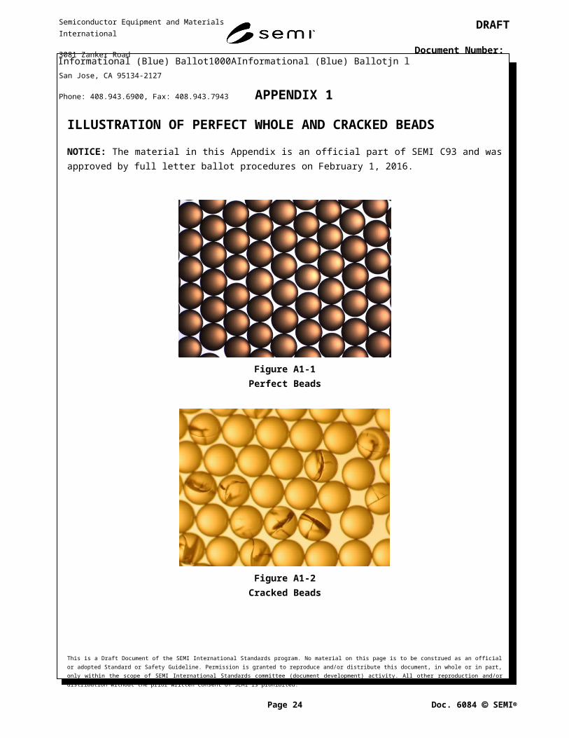
APPENDIX 1
ILLUSTRATION OF PERFECT WHOLE AND CRACKED BEADS
NOTICE: The material in this Appendix is an official part of SEMI C93 and was approved by full letter ballot procedures on February 1, 2016.
Figure A1-1Perfect Beads
Figure A1-2Cracked Beads
This is a Draft Document of the SEMI International Standards program. No material on this page is to be construed as an official or adopted Standard or Safety Guideline. Permission is granted to reproduce and/or distribute this document, in whole or in part, only within the scope of SEMI International Standards committee (document development) activity. All other reproduction and/or distribution without the prior written consent of SEMI is prohibited.
Page 17 Doc. jn l SEMI
Semiconductor Equipment and Materials International
3081 Zanker Road
San Jose, CA 95134-2127
Phone: 408.943.6900, Fax: 408.943.7943

DRAFT
Document Number:
APPENDIX 2
VALIDATION TESTING OF THE RESIN QUALITY ASSESSMENT PROCEDURE
NOTICE: The material in this Appendix is an official part of SEMI C93 and was approved by full letter ballot procedures on February 1, 2016.
A2-1 Validation Testing for the Resin Quality Assessment Procedure
A2-1.1 Prepared by Balazs and CT Associates, Inc. of the SEMI IX Task Force.
A2-2 Dynamic Rinse Testing
A2-2.1 Test Parameters
Particles by Liquid Nano-particle Sizing System (LNS).
Organics by TOC.
Nonvolatile residue by NRM.
Performed by CT Associates, Inc.
1 inch PVDF columns.
Samples provided by Siemens, Lanxess, Purolite, Itochu (Mitsubishi), and Kurita.
The data is presented anonymously with no indication of the specific names of the vendors that provided the samples for the analyses. The results are provided in a random order of samples, using the same letter assignments to suppliers were used in the dynamic and static tests.
Table A2-1 Background Levels
Resin Sample TOC (ppb) NVR (ppt) Particles ≥ 10 nm (#/mL)
A 0.69 220 1.29 × 10⁷
B 0.65 209 1.20 × 10⁷
C 0.79 262 1.22 × 10⁷
D 0.71 241 1.40 × 10⁷
E 0.68 226 1.40 × 10⁷
F 0.49 197 1.14 × 10⁷
Spool#1 0.66 238 1.51 × 10⁷
Average 0.67 228 1.31 × 10⁷
Standard Deviation 0.09 22 1.33 × 10⁶
Cv (%) 13.6% 9.5% 10.1%
1.9 0.18 42 2.60 × 10⁶
#1 ‘Spool’ represents the test resin column with no resin.
This is a Draft Document of the SEMI International Standards program. No material on this page is to be construed as an official or adopted Standard or Safety Guideline. Permission is granted to reproduce and/or distribute this document, in whole or in part, only within the scope of SEMI International Standards committee (document development) activity. All other reproduction and/or distribution without the prior written consent of SEMI is prohibited.
Page 18 Doc. jn l SEMI
Semiconductor Equipment and Materials International
3081 Zanker Road
San Jose, CA 95134-2127
Phone: 408.943.6900, Fax: 408.943.7943

DRAFT
Document Number:
Flush Volume (liters UPW)
1 10 100 1000
Cum
ulative Particle C
oncentration Added
(#/mL > 10 nm
)
1e+5
1e+6
1e+7
1e+8
1e+9
Resin AResin BResin CResin DResin EResin FSpool
Figure A2-1Cumulative Particle Concentration Measured in Dynamic Leach Test
Flush Volume (liters UPW)
0 500 1000 1500 2000
Cum
ulative Particle C
oncentration (#/m
L > 10 nm)
1e+6
1e+7
1e+8
1e+9
1e+10
Resin AResin BResin CResin DResin EResin FSpoolAve Background
Figure A2-2Cumulative Particle Concentration Measured in Dynamic Leach Test (linear coordinates)
This is a Draft Document of the SEMI International Standards program. No material on this page is to be construed as an official or adopted Standard or Safety Guideline. Permission is granted to reproduce and/or distribute this document, in whole or in part, only within the scope of SEMI International Standards committee (document development) activity. All other reproduction and/or distribution without the prior written consent of SEMI is prohibited.
Page 19 Doc. jn l SEMI
Semiconductor Equipment and Materials International
3081 Zanker Road
San Jose, CA 95134-2127
Phone: 408.943.6900, Fax: 408.943.7943

DRAFT
Document Number:
Flush Volume (liters)
500 1000 1500 2000
Non-volatile residue (ppt)
0
1000
2000
3000
4000
5000
Resin AResin BResin CResin DResin EResin FSpoolAve. Background
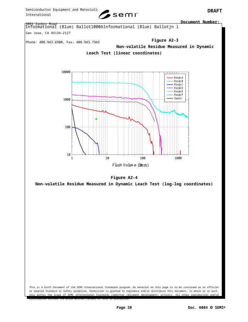
Figure A2-3Non-volatile Residue Measured in Dynamic Leach Test (linear coordinates)
Flush Volume (liters)
1 10 100 1000
Non-volatile residue added (ppt)
10
100
1000
10000
Resin AResin BResin CResin DResin EResin FSpool
Figure A2-4Non-volatile Residue Measured in Dynamic Leach Test (log-log coordinates)
This is a Draft Document of the SEMI International Standards program. No material on this page is to be construed as an official or adopted Standard or Safety Guideline. Permission is granted to reproduce and/or distribute this document, in whole or in part, only within the scope of SEMI International Standards committee (document development) activity. All other reproduction and/or distribution without the prior written consent of SEMI is prohibited.
Page 20 Doc. jn l SEMI
Semiconductor Equipment and Materials International
3081 Zanker Road
San Jose, CA 95134-2127
Phone: 408.943.6900, Fax: 408.943.7943

DRAFT
Document Number:
Flush Volume (Liters)
1 10 100 1000
TOC
(ppb)
0
2
4
6
8
10
12
14 Resin AResin BResin CResin DResin EResin FSpoolAve. Background
Figure A2-5TOC Measured in Dynamic Leach Test (linear-log coordinates)
Flush Volume (Liters)
1 10 100 1000
TOC
added (ppb) 0.01
0.1
1
10
100
Resin AResin BResin CResin DResin EResin FSpool
Figure A2-6TOC Measured in Dynamic Leach Test (log-log coordinates)
16: Unstable TOC values at the end of the experiments were due to the effect of the UPW temperature on the TOC leachouts from the tested resin (TOC instrument provided temperature compensation).This is a Draft Document of the SEMI International Standards program. No material on this page is to be construed as an official or adopted Standard or Safety Guideline. Permission is granted to reproduce and/or distribute this document, in whole or in part, only within the scope of SEMI International Standards committee (document development) activity. All other reproduction and/or distribution without the prior written consent of SEMI is prohibited.
Page 21 Doc. jn l SEMI
Semiconductor Equipment and Materials International
3081 Zanker Road
San Jose, CA 95134-2127
Phone: 408.943.6900, Fax: 408.943.7943

DRAFT
Document Number:
Table A2-2 Dynamic Leach Summary
Sample ID
Particles ≥10 nm NVR TOC
1 × 10⁷/mL added
(liters UPW)
1 × 10⁷/mL added
(liters UPW)
500 ppt added (liters UPW)
50 ppt added (liters UPW)
1 ppb added (liters UPW)
0.2 ppb added (liters UPW
A 140 760 2 160 65 1800
B 16 40 <1 <10 25 120
C 170 820 <1 <10 80 >1800
D 250 900 190 300 140 >1800
E 1020 >2000 240 2000 215 >1800
F 190 1100 140 NA 205 1000
Spool 3 50 <1 <10 <1 <1
A2-3 Static Leach Testing
A2-3.1 Test Parameters
Metals by ICPMS.
Particles by LPC, SEM, and LNS.
Organics by TOC and LC-OCD.
Performed by Air Liquide, Balazs.
o 500 mL PFA container, Volume ratio 1:1 UPW to resin thorough pre-rinse 40°C leach (15 hours), followed by 1 hour agitation.
o Samples provided by Siemens, Lanxess, Purolite, Itochu (Mitsubishi), and Kurita.
o The data is presented anonymous with random order of samples used.
Numbering of the resin in both Dynamic and Static leach tests is consistent.
Table A2-1 TOC and TOC Speciation of the Static Leach Samples
Organics, ppb
Resin Sample ID
TOCDOC HOC HMW
LMW Acids
LM W Neutral
X1 X2 X3
LC-OCD
A 150 222 3 22 6 8 65 103 16
B 89 180 ND 37 8 38 50 52 3
C 220 295 ND 30 8 135 62 52 13
D 250 252 7 12 ND 68 30 101 39
E 190 261 12 52 5 30 35 107 26
This is a Draft Document of the SEMI International Standards program. No material on this page is to be construed as an official or adopted Standard or Safety Guideline. Permission is granted to reproduce and/or distribute this document, in whole or in part, only within the scope of SEMI International Standards committee (document development) activity. All other reproduction and/or distribution without the prior written consent of SEMI is prohibited.
Page 22 Doc. jn l SEMI
Semiconductor Equipment and Materials International
3081 Zanker Road
San Jose, CA 95134-2127
Phone: 408.943.6900, Fax: 408.943.7943

DRAFT
Document Number:
F 250 336 ND 35 4 91 40 56 119
Baseline ND N/A
#1 HOC – hydrophobic, HMW – high molecular weight, LMW – low molecular weight.
#2 Synthetic Compounds: X1 – matches retention time of ethanol, X2 – matches retention time of methanol, X3 – matches retention time of TMA.
This is a Draft Document of the SEMI International Standards program. No material on this page is to be construed as an official or adopted Standard or Safety Guideline. Permission is granted to reproduce and/or distribute this document, in whole or in part, only within the scope of SEMI International Standards committee (document development) activity. All other reproduction and/or distribution without the prior written consent of SEMI is prohibited.
Page 23 Doc. jn l SEMI
Semiconductor Equipment and Materials International
3081 Zanker Road
San Jose, CA 95134-2127
Phone: 408.943.6900, Fax: 408.943.7943
DRAFT
Document Number:
Figure A2-1LC-OCD Chromatogram
This is a Draft Document of the SEMI International Standards program. No material on this page is to be construed as an official or adopted Standard or Safety Guideline. Permission is granted to reproduce and/or distribute this document, in whole or in part, only within the scope of SEMI International Standards committee (document development) activity. All other reproduction and/or distribution without the prior written consent of SEMI is prohibited.
Page 24 Doc. jn l SEMI
Biop
olym
ers
Build
ing
Bloc
ks
LMW
Aci
ds
Amm
oniu
m
Bypa
ss
X2 X3
Resin 14-00938
Resin 14-00943
Resin 14-00944
Resin 14-00958
Resin 14-00960
Resin Lot CHS 50007
X1
0
0,5
1
1,5
2
2,5
3
3,5
4
0 50 100 150 200
Retention Time in Minutes
rel.
Sig
nal R
espo
nse
-- OCD-- UVD-- OND
Project:Balazs_130
D
B
C
E
F
A
Semiconductor Equipment and Materials International
3081 Zanker Road
San Jose, CA 95134-2127
Phone: 408.943.6900, Fax: 408.943.7943

DRAFT
Document Number:
Figure A2-2Particle Images by SEM
Particle Diameter (nm)
10 20 30 40 50 60 80 100
Cum
ulative Num
ber Concentration (#/m
L)
1e+6
1e+7
1e+8
1e+9
Resin AResin BResin CResin DResin EResin FBlank
Figure A2-3Grab Sample Particle Leach Analysis by LNS
This is a Draft Document of the SEMI International Standards program. No material on this page is to be construed as an official or adopted Standard or Safety Guideline. Permission is granted to reproduce and/or distribute this document, in whole or in part, only within the scope of SEMI International Standards committee (document development) activity. All other reproduction and/or distribution without the prior written consent of SEMI is prohibited.
Page 25 Doc. jn l SEMI
Semiconductor Equipment and Materials International
3081 Zanker Road
San Jose, CA 95134-2127
Phone: 408.943.6900, Fax: 408.943.7943

DRAFT
Document Number:
Table A2-2 Grab Sample Particle Leach Analysis by LNS
Resin IDCumulative Concentration x 106 (#/mL)
≥10 nm ≥20 nm ≥30 nm
A 121 11.6 1.32
B 65 4.5 0.27
C 125 18.0 6.42
D 87 9.7 1.29
E 225 30.0 7.02
F 3052 92.6 26.8
Blank 31 2.7 0.51
Table A2-3 Grab Sample Particle Leach Results of LPC and SEM Analyses
Resin IDLPC, particles per mL SEM
>0.3 µm >0.5 µm >1 µm >2 µm 0.1–0.2 µm 0.2–0.5 µm 0.5–1 µm >1 µm
A 56,000 17,000 2,300 460 1500 ± 100 190 ± 20 97 ± 10 ND
B 290 84 7.5 0.7 97 ±10 <49 <49 <49
C 930,000 140,000 11,000 1,200 44000 ± 4000 3200 ± 300 630 ± 60 340 ± 30
D 45,000 12,000 880 97 1200 ± 100 150 ± 10 49 ± 5 49 ± 5
E 34,000 13,000 220 310 1300 ± 100 150 ± 10 49 ± 5 49 ± 5
F 41,000 6,400 550 91 1800 ± 200 290 ± 30 49 ± 5 49 ± 5
Blank 39 6.8 0.8 0.3 <49 <49 <49 <49
Table A2-4 Static Leach Metal Analysis by UPW Extraction
Resin Sample ID
Metals
Elements Detected Concentration, ng/mL (resin)
Detection Limits, ng/mL (resin)
A None ND 0.002–0.08
B None ND 0.002–0.08C Fe
K
Na
0.04
0.06
0.07
0.02
0.02
0.01
D None ND 0.002–0.08
E None ND 0.002–0.08
F None ND 0.002–0.08
This is a Draft Document of the SEMI International Standards program. No material on this page is to be construed as an official or adopted Standard or Safety Guideline. Permission is granted to reproduce and/or distribute this document, in whole or in part, only within the scope of SEMI International Standards committee (document development) activity. All other reproduction and/or distribution without the prior written consent of SEMI is prohibited.
Page 26 Doc. jn l SEMI
Semiconductor Equipment and Materials International
3081 Zanker Road
San Jose, CA 95134-2127
Phone: 408.943.6900, Fax: 408.943.7943

DRAFT
Document Number:
Blank None ND 0.002–0.08
#1 30 elements were tested by high resolution ICPMS.
#2 Only those above detection limits were reported.
#3 Detection limits are 1–40 ppt in H2O for the metals tested (i.e., Ag, Al, As, Au, B, Ba, Be, Bi, Ca, Cd, Ce, Co, Cr, Cs, Cu, Fe, Ga, Ge, Hg, K, Li, Mg, Mn, Mo, Na, Ni, Pb, Sn, Sr,Ti, W, Zr).
Table A2-5 HCl Leach for Metals
Elements RL Unit
IX Resin Sample ID
A B C D E F
Aluminum (Al) 0.1 ppb (ng/g) 0.5 1.7 5.6 6 0.2 2.6
Antimony (Sb) 0.1 ppb (ng/g) * * * * * *
Arsenic (As) 0.2 ppb (ng/g) 0.4 * * * * *
Barium (Ba) 0.05 ppb (ng/g) 0.08 * 0.11 0.09 * *
Beryllium (Be) 0.1 ppb (ng/g) * * * * * *
Boron (B) 1 ppb (ng/g) 5 * 22 * * 2
Cadmium (Cd) 0.1 ppb (ng/g) * * * * * *
Calcium (Ca) 1 ppb (ng/g) 12 2 85 8 2 19
Chromium (Cr) 0.1 ppb (ng/g) 7.1 1 3.6 4.9 7.9 10
Cobalt (Co) 0.05 ppb (ng/g) 0.19 * 0.09 * 0.05 0.23
Copper (Cu) 0.1 ppb (ng/g) 0.3 0.2 0.1 * * 0.4
Gallium (Ga) 0.1 ppb (ng/g) * * * * * *
Germanium (Ge) 1 ppb (ng/g) * * * * * *
Gold (Au) 1 ppb (ng/g) * * * * * *
Iron (Fe) 1 ppb (ng/g) 330 2 21 4 4 110
Lead (Pb) 0.1 ppb (ng/g) * * * * * 0.1
Lithium (Li) 0.05 ppb (ng/g) * * * * 0.16 *
Magnesium (Mg) 0.1 ppb (ng/g) 20 0.3 20 0.5 0.4 9
Manganese (Mn) 0.1 ppb (ng/g) 6.2 * 0.5 * * 2.1
Molybdenum (Mo) 0.1 ppb (ng/g) 0.4 0.5 0.3 2.7 * 2.2
Nickel (Ni) 0.1 ppb (ng/g) 7.6 0.2 0.9 5.1 0.7 26
Potassium (K) 1 ppb (ng/g) 14 1 11 4 * 3
Silver (Ag) 0.5 ppb (ng/g) * * * * * *
Sodium (Na) 0.1 ppb (ng/g) 710 5 96 6.6 2.8 62
Strontium (Sr) 0.05 ppb (ng/g) 0.13 * 0.56 0.11 0.09 0.14
Tin (Sn) 0.1 ppb (ng/g) * * * * * *
Titanium (Ti) 1 ppb (ng/g) * * * * * *
Vanadium (V) 0.1 ppb (ng/g) * * * * * *
Zinc (Zn) 1 ppb (ng/g) * * * * * *
This is a Draft Document of the SEMI International Standards program. No material on this page is to be construed as an official or adopted Standard or Safety Guideline. Permission is granted to reproduce and/or distribute this document, in whole or in part, only within the scope of SEMI International Standards committee (document development) activity. All other reproduction and/or distribution without the prior written consent of SEMI is prohibited.
Page 27 Doc. jn l SEMI
Semiconductor Equipment and Materials International
3081 Zanker Road
San Jose, CA 95134-2127
Phone: 408.943.6900, Fax: 408.943.7943
DRAFT
Document Number:
Zirconium (Zr) 0.1 ppb (ng/g) 0.2 0.7 0.2 0.2 * *
Bismuth (Bi) 0.1 ppb (ng/g) * * * * * *
Mercury (Hg) 1 ppb (ng/g) * * * * * *
Tungsten (W) 1 ppb (ng/g) * * * * *
NOTICE: SEMI makes no warranties or representations as to the suitability of the Standards and Safety Guidelines set forth herein for any particular application. The determination of the suitability of the Standard or Safety Guideline is solely the responsibility of the user. Users are cautioned to refer to manufacturer’s instructions, product labels, product data sheets, and other relevant literature, respecting any materials or equipment mentioned herein. Standards and Safety Guidelines are subject to change without notice.
By publication of this Standard or Safety Guideline, SEMI takes no position respecting the validity of any patent rights or copyrights asserted in connection with any items mentioned in this Standard or Safety Guideline. Users of this Standard or Safety Guideline are expressly advised that determination of any such patent rights or copyrights and the risk of infringement of such rights are entirely their own responsibility.
This is a Draft Document of the SEMI International Standards program. No material on this page is to be construed as an official or adopted Standard or Safety Guideline. Permission is granted to reproduce and/or distribute this document, in whole or in part, only within the scope of SEMI International Standards committee (document development) activity. All other reproduction and/or distribution without the prior written consent of SEMI is prohibited.
Page 28 Doc. jn l SEMI
Semiconductor Equipment and Materials International
3081 Zanker Road
San Jose, CA 95134-2127
Phone: 408.943.6900, Fax: 408.943.7943


![Science Volume 336 Issue 6084 2012 [Doi 10.1126%2Fscience.336.6084.973] Gibbons, A. -- An Evolutionary Theory of Dentistry](https://static.fdocuments.us/doc/165x107/577cc5351a28aba7119bacd4/science-volume-336-issue-6084-2012-doi-1011262fscience3366084973-gibbons.jpg)