File D. B. *1'~~~~~~~~~~~~~~~~~~~~~1-...
26
File 18G: D.B. 002830 *1'~~~~~~~~~~~~~~~~~~~~~1- tIM Project No. 11206.11 THERMAL TREATMENT WORK PLAN FOR STOCKPILED FUEL CONTAMINATEII SOILS AT EJELSON MIR FORCE BASE Prepared for Arustrong Laboratory Brooks Mir Force Base San Antonio, Texas Prepared by EA Engineering, Science, and Technology Northwest Operations Redmond, Washington 23 July 1991
Transcript of File D. B. *1'~~~~~~~~~~~~~~~~~~~~~1-...

File 18G:D. B.
002830*1'~~~~~~~~~~~~~~~~~~~~~1- tIMProject No. 11206.11
THERMAL TREATMENT WORK PLAN FOR STOCKPILEDFUEL CONTAMINATEII SOILS AT EJELSON MIR FORCE BASE
Prepared for
Arustrong LaboratoryBrooks Mir Force Base
San Antonio, Texas
Prepared by
EA Engineering, Science, and TechnologyNorthwest Operations
Redmond, Washington
23 July 1991
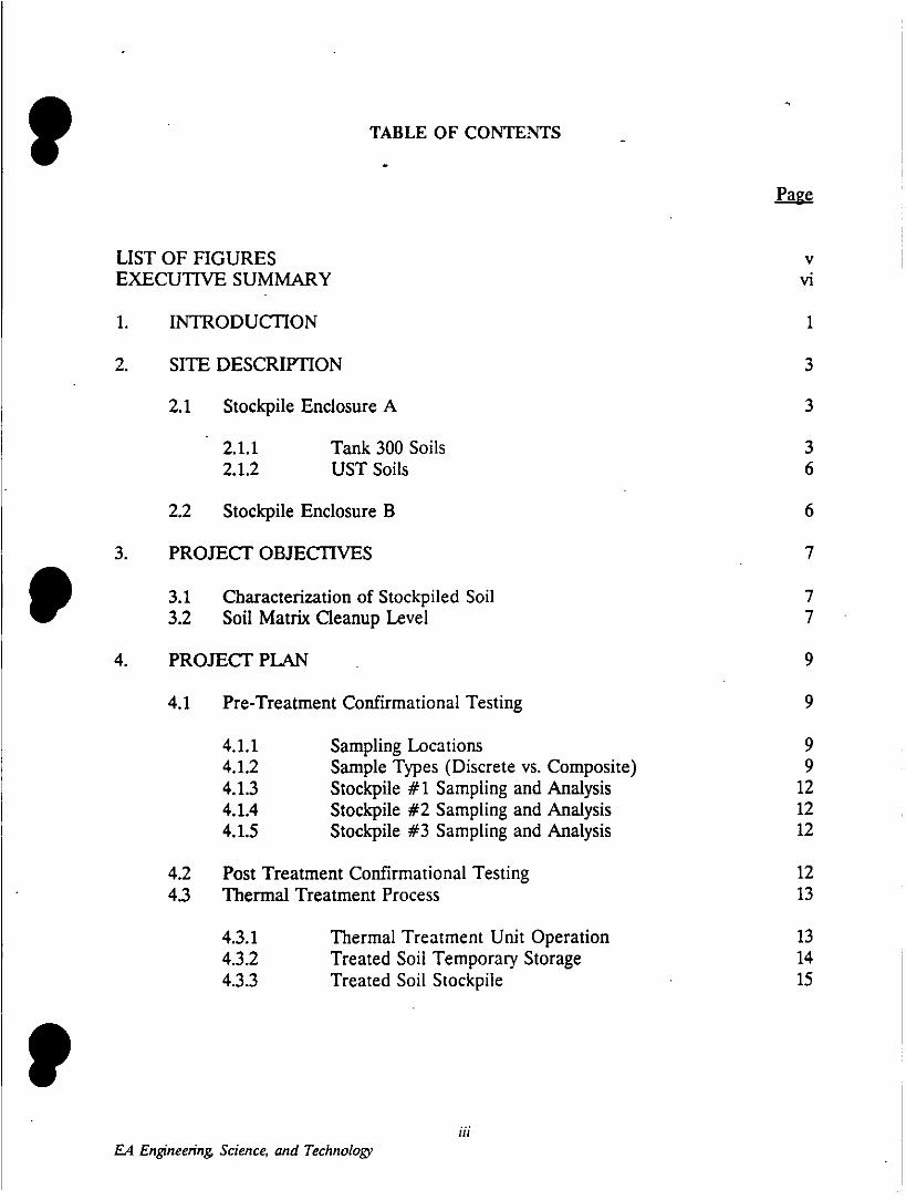
TABLE OF CONTENTS
LIST OF FIGURES VEXECUTIVE SUMMARY vi
1. INTRODUCTION 1
2. SITE DESCRIPTION 3
2.1 Stockpile Enclosure A 3
2.1.1 Tank 300 Soils 32.1.2 UST Soils 6
2.2 Stockpile Enclosure B 6
3. PROJECT OBJECTIVES 7
3.1 Characterization of Stockpiled Soil 77
3.2 Soil Matrix Cleanup Level7
4. PROJECT PLAN 9
4.1 Pre-Treatment Confirmational Testing 9
4.1.1 Sampling Locations 94.1.2 Sample Types (Discrete vs. Composite) 94.1.3 Stockpile #1 Sampling and Analysis 124.1.4 Stockpile #2 Sampling and Analysis 124.1.5 Stockpile #3 Sampling and Analysis 12
4.2 Post Treatment Confirmational Testing 124.3 Thermal Treatment Process 13
4.3.1 Thermal Treatment Unit Operation 134.3.2 Treated Soil Temporary Storage 144.3.3 Treated Soil Stockpile 15
IP~~~~~~~~~~~~~~~~~~~~~H
LA4 Engineering Science, and Technology

TABLE OF CONTENTS, CONTD
Page
5. QUALITY ASSURANCE AND QUALITY CONTROL 16
5.1 Sample Collection, Handling, and Custody 16
5.1.1 Soil Samples 16
5.2 Laboratory QA/OC 18
6. HEALTH AND SAFETY 19
7. SCHEDULE 20
REFERENCES 21
iv
E4 Engineering Science, and Technology

LIST OF FIGURES
Number TilePagZe
1 Project Site Map 4
2 Configuration of Fuel Contaminated Soil
Stockpiles 5
3 Soil Sampling Locations, Stockpile #1,
Enclosure A 10
4 Soil Sampling Locations, Stock~piles #2 and #3,Enclosure B 11
5 Chain of Custody Form for Analytical Samples 17
EA Engineering. Science, and Technology

EXECUTIVE SUMMARY
This document outlines the projedt plan for remediation of petroleum fuel contaminatedsoils that are stockpiled at Eielson Air Force Base (EAFB). Over the past two years,petroleum contaminated soils that have been encountered during maintenance activities onthe Base have been stockpiled in a designated storage area. EAFB plans to rernediate thesesoils using thermal treatment technology so that they meet all existing Alaska Departmentof Environmental Conservation (ADEC) guidelines for cleanup of petroleum contaminatedsoils.
The project plan includes pre-treatment sampling to confirm that the contamination isprimarily petroleum hydrocarbon fuels and to characterize the contamination. The plan alsoincludes post-treatment sampling to confirm that the treated soils meet ADEC cleanupguidelines. The thermal treatment unit is a mobile rotary kiln that operates at 6500 to 8500F, with a 1,5000 afterburner for residual off-gases. It will be operated on a 24-hour schedulefor approximately six weeks, beginning in mid-September 1991.
F-4 Engineering Science, and Technzolog
1. INTRODUCTON
During ongoing maintenance and facility upgrading operations at Fielson Air Force Base(EAFB) over the past 2 years, petroleum hydrocarbon contaminated soils have beenencountered at several locations. These soils have been excavated and stockpiled in adesignated storage area on the Base. Available information indicates that the soilcontamination is primarily petroleum fuels (JP-4, diesel, and gasoline) and that theconcentrations of petroleum hydrocarbons in the stockpiled soils exceed the State of Alaskaclean-up guidelines. During the fall of 1991, EAFB proposes to remediate the presentlystockpiled petroleum contaminated soils utilizing thermal treatment technology. Thisdocument presents the proposed project plan for achieving this goal and is intended to meetall of the requirements of the State of Alaska for reporting the proposed soil remediationactivities.
EAFB is proposing to thermally treat these stockpiled soils in order to reduce the potentialrisk to the environment as well as to evaluate the inmplementability and cost effectivenessof this technology. The basic project approach will be: (1) to perform pre-treatmentsampling of the contaminated soils both to confirm that the contamination is only petroleumfuels and to characterize the contaminant types and concentrations; (2) to thermally treatthe soils utilizing a rotary kiln and afterburner; (3) to perform post-treatment confirmational.testing to document that the treatment process has successfully reduced the petroleumP ~~hydrocarbon contamination to below Alaska Department of Environtmental Conservation(ADEC) clean-up level guidelines; and (4) to stockpile the treated soils for use by the Baseas cover materials for the Asbestos Landfill or possible other uses.
It is anticipated that cold weather and/or air quality considerations will require thattreatment activities be halted by late October. This will limit the quantity of soil to beprocessed during 1991 to a maximum of about 10,000 tons, given the capacity of theequipment proposed for treatment and an anticipated start-up date of September 1st. T'hevendor who supplies the soil remediation unit will be required to have a current ADEC airquality permit and the analytical laboratory will have current ADEC certification in orderto facilitate ADEC approval of the proposed project plan.
In addition to this section, 1. INTRODUCTION, this work plan includes the followingsections:
* 2. SITE DESCRIPTION - This section provides a description of the stockpilesand the thermal treatment site. Also outline in this section is the knownsources of the material in each stockpile. The currently available datacharacterizing the types and levels of contamination in each stockpile aresummarized and supporting documentation is referenced.
* 3. PROJECT OBJECTIVES - The overall project objective of remediation ofstockpiled petroleum contaminated soils is discussed and specific cleanup
goals and data quality objectives are outlined.
EA Engineering Science, and Technology

4. PROJECT' PLAN - This section provides the detailed plan for the soilremediation. The nu mber and location of pre-treatment samples, the numberand schedule for post-treatment samples, and the laboratory analyses for eachsample are outlined. A brief description is provided of the functionaloperation of the thermal treatment unit and the general materials handlingaspects of the project.
5. QUALITY ASSURANCE and QUALITY CONTROL - This sectionoutlines the sample collection and handling procedures that will be followedduring the conduct of this project. The laboratory QA/QC requirements willbe met by utilizing a laboratory which has been certified by ADEC.
* 6. HEALTH and SAFETY - Health and safety plans will be developed fortwo different phases of the project. One document will be prepared for thepre-treatment sampling and a second document will be prepared for theincineration operation and post-treatment confirmational sampling. Thedocuments will be referenced in this section and their contents brieflydiscussed.
* 7. PROJECT SCHEDULE - The implementation schedule for the project isoutlined and critical activities affecting the schedule are discussed.
EA Engineering Science, and Technology

f ~~~~~~~2. SITE DESCRIPTION
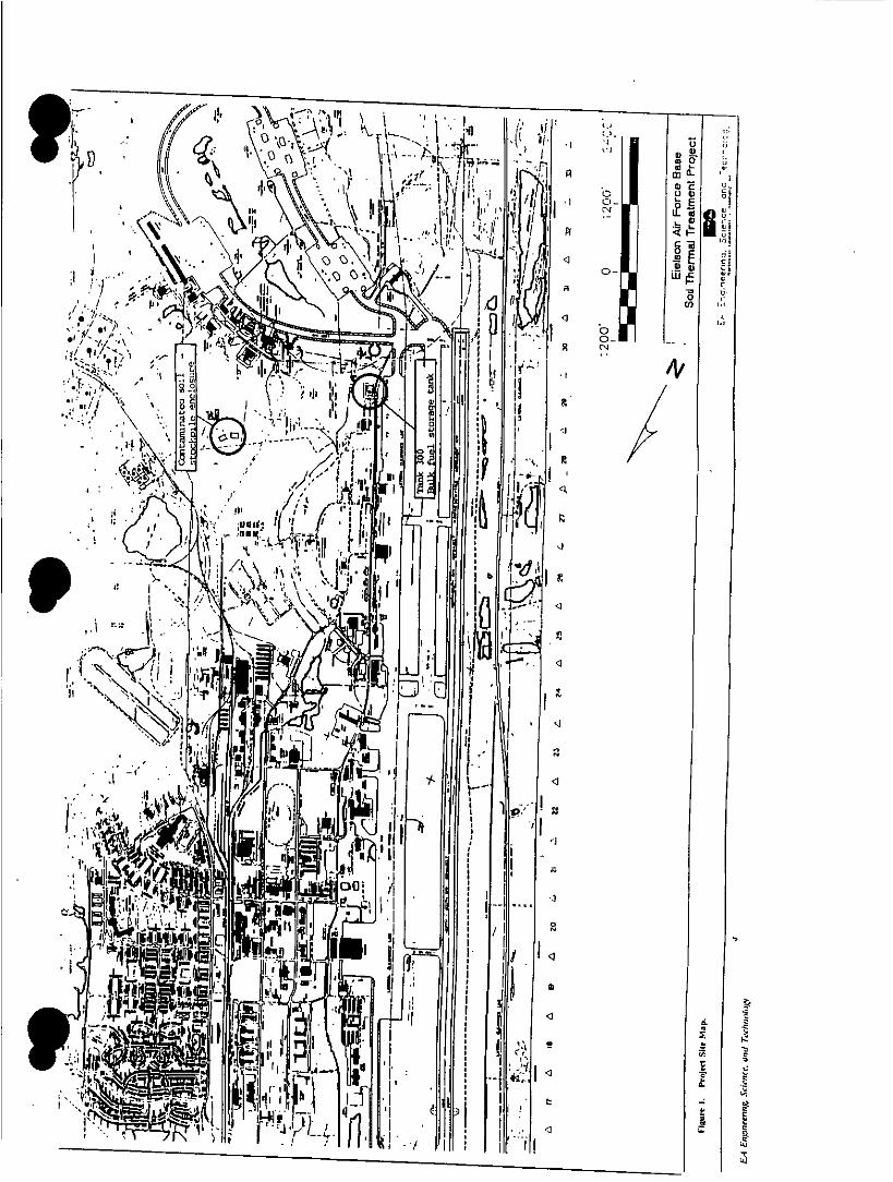
EAFB presently maintains two stdckpile enclosures on the Base which contain petroleumcontaminated soil. These enclosures are adjacent to each other and are located in thevicinity of the Asbestos Landfill (Figure 1). The first stockpile enclosure (Enclosure A) wasconstructed during the spring of 1990 (Figure 2). Contaminated soils from the vicinity ofthe Tank 300 bulk storage tank were moved into this enclosure during the summer of 1990.The second stockpile enclosure (Enclosure B) was constructed during the Fall of 1990. Thisenclosure was constructed to provide a temporary storage location for contaminated soilsthat were excavated during the construction of the new Dining Hall facility.
2.1 Stockpile Enclosure A
Stockpile Enclosure A was constructed during 1990 to provide a temporary storage area forsoils that had been stockpiled in the vicinity of Tank 300. The enclosure has an area ofapproximately 26,000 ft2. The area is enclosed with a berm which is approximately 3 ft highand, based on visual observations, has a polyethylene bottom liner covered with gravel. Nodocuments are available which describe the enclosure materials or installation andconstruction methods. A single stockpile consisting of approximately 4,300 yd 3 Of Soil(Stockpile #1), is located within the enclosure. The stockpile covers the majority of theenclosure and the pile is up to 7 feet thick in some areas. The top of the stockpile is not' ~~covered,
Based on discussions with Mr. Brent Koenen of the 343 Civil Engineering Squadron(Koenen, 1991), the majority of these soils originated from a JP-4 fuel leak from the Tank300 bulk fuel storage tank. The remainder of the soils are believed to have originated fromthe removal of underground storage tanks (USTs) on the Base during 1990. However, thereare no available records identifying all of the sources, the quantities of materials taken fromeach source, or contamination characterization of the excavated soils.
2.1.1 Tank 300 Soils
Tank 300 is a bulk fuel storage tank that contains JP-4 jet fuel. In 1990 a leak in the tankwas detected and repaired. Fuel contaminated soils were excavated from around the tankand were temporarily stockpiled adjacent to the tank. During the time that these soils werestored adjacent to the tank, the area became the temporary storage area for fuelcontaminated soils from various other locations on the Base. Some soils, which originatedfrom the excavations associated with USTs removed during 1990, were also stored in thisarea.
During the summer of 1990, all soils stockpiled at the Tank 300 bulk fuel storage area weremoved to Stockpile Enclosure A. There has been no further characterization of the soilsP ~~within the stockpile.
3EA Engineering. Science, and Technology
)~~~~~~HII0
IL q A~~~~~~~~t &\ ~~~~~~~ ciW;
if1) t *1~~~~~~~~~~~~A
/ - -- - -- - --
CJ~~~~~~~~~ -r..j....

ASBESTOS LANDFILL
p . _ _ _ _~~~~~~~~~
STOCKPILE'ENCLOSURE A
STOCKPILEENCLOSURE B
237'
E ~C:
146'~ ~ 100' 50' 0 100' 200
/STIOCKPILE STOCKP!'LE#2 #~Eielson Air Force Base
Soil Thermal Treatment ProjectU ; ti..0~~~- . Conflcurotion i
.cfl~zmr~steJ Zz~: C s. EA Engineer<no. Scienceoc h
£,4 Engineering Science, and Technology'

P~~2.1.2 UIST Soils
During 1990, nine LISTs were removed on Eielson Air Force Base. EAFB notified ADECthat these tanks would be removed on May 11,1990 (Hinchee, 1990). During tank removal,some samples were collected and analyzed for total petroleum hydrocarbons (T`PH) by EPAmethod 418.1 and benzene, toluene, ethylbenzene and xylene (BTEX) by EPA Method 8020(Keiling, 1991). Utilizing field screening tools and the results of laboratory data, EAFBpersonnel directed the removal of contaminated soils from the LIST sites. These soils wereadded to the temporary stockpile at the Tank 300 site. There are no available records ofthe quantities of soils excavated from each LIST site and placed in the Tank 300 area. Theremay have been other sources of fuel contaminated soils in addition to those that wereexcavated with the tanks identified in the notification letter. However, there are no recordsidentifying the sources or quantities of materials.
2.2 Stockpile Enclosure B
Stockpile Enclosure B was constructed during the spring of 1991 in connection with a planto temporarily stockpile fuel contaminated soils that were encountered during the excavationof the foundation for the Dining Hall facility. The design specifications for the enclosurewere submitted for ADEC review on October 4, 1990 (Davis Construction, 1990; Markey,1990). The enclosure has an estimated area of 35,000 ft2. It has a 30-mil reinforcedP ~~polyethylene bottom liner covered with a minimum of 6 inches of gravel. There are twostockpiles located within the enclosure, Stockpile #2 and Stockpile #3 (Figure 2). Both ofthese stockpiles originated from the excavation for the Dining Hall facility.
Stockpile #2 consists of approximately 1,300 yd 3 of soils, and has been characterized withboth field screening and laboratory analyses as containing petroleum fuels with T`PHconcentrations as high as 30,000 mg/kg (ESI, 1991). The stockpile is approximately 5.5 fthigh and is covered with a polyethylene liner.
Stockpile #3 consists of approximately 140 yd 3 of soils that reportedly have TPHconcentrations up to 30,000 mg/kg, but the contaminants may not be fuel compounds.Pesticides were suspected by the consultant based on preliminary interpretations of field-screening (photovac PID) data, but laboratory tests (EPA Method 8080) indicate that thesecompounds are not present. At this time, the contamination in Stockpile #3 has not beenfully characterized (ESI, 1990). The stockpile is approximately 4.5 ft high and is coveredwith a polyethylene liner.
6EA Engineering, Science, and Technolog'
3. PROJECT OBJECTIVES
The ultimate project objective is to remediate soils containing petroleum hydrocarbons thatare currently stored in above-ground stockpiles at EAFB.
The following phases of the project will be carried out in pursuit of this objective:
Phase 1: Characterize the composition and concentration of petroleumhydrocarbons in the existing stockpiles. Soil samples will be analyzedto ensure that the soils do not constitute RCRA-regulated wastes.
Phase 2: Remediate the stockpiles using a thermal treatment process andcharacterize the concentrations of hydrocarbons in the treated soils toverify that the required cleanup standards have been achieved.
3.1 Characterization of Stockpiled Soil
The soil contained in the above-ground stockpiles was excavated during 1990 from severaldifferent areas of EAFB (as described above in Section 2) and was transported to thepresent stockpile locations. The petroleum hydrocarbons in the soil are believed to consistprimarily of fuels (JP-4 jet fuel, gasoline, and diesel) that were released to the soil duringp ~~operation of one large above-ground tank and nine underground tanks.
EAFB encompasses a number of hazardous waste areas that are known to contain RCRAwastes. It is the understanding of EAFB personnel that no soil containing RCRA-regulatedcompounds was included in the soils added to the stockpiles. Because writtendocumentation of the source of the soil to be treated is not complete, discrete soil samplesfrom Stockpiles #1 and #2 will be analyzed for the presence of volatile halogenated by EPAMethod 8010 total volatile petroleum hydrocarbons (TVPH) and total extractable petroleumhydrocarbons (TEPH) by EPA Method 8015, aromatic volatile organics by EPA Method8020, and leachable metals by EPA toxicity characteristic leaching procedure (TCLP)methods.
Discrete soil samples from Stockpile #3 will be analyzed for volatile organics by EPAMethod 8240, semi-volatile organics by EPA Method 8270, and TCLP metals.
3.2 Soil Matrix Cleanup Level
The Alaska Department of Environmental Conservation has established interim guidelinesfor cleanup levels applicable to remediation of~ petroleum contaminated soils (ADEC 1991c).The guidelines describe a ranking system (Table I Matrix) that permits selection of finalcleanup criteria based on the hydrogeologic setting of the site and the local groundwateruses. An alternative to selection of a cleanup level using the matrix ranking is to adopt the' ~~strictest of the recommended cleanup levels. The most stringent cleanup level specified bythe guidelines is 50 mg/kg TPH as gasoline and 100 mg/kg TPH as diesel.
EA Engineering Science, and Technology
' ~~Because EA.FB personnel have elected to remediate the soil using a thermal treatmentprocess (described below in section 4.3) that will volatilize the hydrocarbons in the soil, itis proposed that the cleanup standard for diesel be applied to the soil treated by thethermal process. Samples of the treated soils will be collected and analyzed by EPAMethod 418.1 to verify that soil TPH levels are less than 100 mg/kg.
Any treated soils found to contain TPH levels greater than 100 mg/kg will be reprocessedand then resampled. Soils which still contain TPH levels exceeding 100 mg/kg TPHsubsequent to the second processing will be analyzed to determine the nature of the residualhydrocarbons. If the soils are found to contain only residual range petroleum hydrocarbons(as defined in ADEC's interim guidance document for non-UST soil cleanup levels), thenthe soils will be considered 'clean' and non-regulated if the residual range hydrocarbons donot exceed ADEC's cleanup level of 2,000 mg/kg for waste oil.
Any processed soils that do not meet AIDEC cleanup guidelines will be temporarily storedin a vacant area of Stockpile Enclosure B, while alternative remediation schemes for thesoils are evaluated.
8EA Engineering. Science, and Technology
f ~~~~~~~4. PROJECT PLAN
4.1 Pre-Treatment Confirmational Testing
The purpose of pre-treatment confirmational testing is to characterize the nature and extentof petroleum hydrocarbon contamination in the stockpiled soils prior to thermal treatment.The sampling strategy outlined in this section is predicated on the assumption that the soilsare contaminated primarily with petroleum hydrocarbons, and that all the soils will requiretreatment (i.e., all soils exceed ADEC's cleanup guidelines). Confirmational samples willbe submitted for analysis from each stockpile to verify that the soils do not qualify asRCRA-controlled hazardous wastes, and to confirm that all the soils will require treatment.
4.1.1 Sampling Locations
A quasi-random approach was used to select sampling locations for confirmational testing.The sampling locations were determined according to a grid placed over each stockpile.The cell sizes of the individual grids were determined by the number of samples to besubmitted from the stockpiles (see below); one sample will be submitted from each cell.The cells were numbered consecutively, starting with the number one. Each cell wassubdivided into four quadrants, labeled A through D. A single quadrant of each cell wasthen selected randomly, and the sampling locations were chosen as the center of the selected' ~~quadrants, The sampling locations for Stockpiles #1-3 are shown in Figures 3 and 4.
At each sampling location, discrete samples will be obtained from two of three possibledepths in the test pits/borings: 2 feet, 3 feet, or 4 feet below the stockpile surface. The twosampling depths at each sampling location were determined by systematically rejecting oneof the three possible depths in consecutive grid cells. The pre-determined sampling depthsmay have to be modified to accommodate variations in stockpile thicknesses or soilcharacteristics, in order to avoid damaging the stockpile enclosure liners or samplingequipment. The sampling team will be responsible for making any such modifications to thesampling plan, based on conditions encountered in the field.
4.1.2 Sample Types (Discrete vs. Composite'
Approximately one third of the samples collected from each stockpile will be analyzed asdiscrete samples, for the purpose of identifying and quantifying types and levels ofcontamination present in the stockpiles. Approximately half of these discrete samples willbe selected based on field screenings with an Organic Vapor Analyzer (OVA -- FoxboroModel Century 128); the samples corresponding to the highest OVA readings will besubmitted to the laboratory for analysis (see Section 5.1.2 for a description of field screeningmethodology). The remainder of the discrete samples submtitted for stockpilecharacterization will be chosen randomly, since an OVA cannot be relied upon to respond
to all potential contaminants of concern.
9EA Engineering. Science, and Technology
0 1~ ~~~~~
Soil Thermal Treatment Projectcure Soil scmc~~~~nc oczt~~zras
S~~<:ie .Ž' :nglneerrg. Science. ona2
£4 Engineerng Science1Technolog

A 0 I
Sto~~~~~il~~~f2 ~~Stccicfui:43
4114~~~~~~~~~~~~0
I _______4__ 2_ 08 0
'7,l Srnpin Ic,~7 Ee nArFreBs*~~~~~~olTema ramn rjc
7~crc C~iOC:t -- 6I
st~xc;e 42 irc -~r n , __f.__e
F-4 Engineering Scie~~~~~~~~~~~xe, and Technolog~ ~~~~~~
The majority of the discrete sample pairs collected from the individual sampling locationswill be composited by the analytical laboratory. No composite sample shall consist of morethan two discrete samples. The composite samples will provide information on the averageconcentrations of petroleum hydrocarbons in the stockpiles.
All samples will be assigned a unique identification number which will indicate the stockpilenumber, sampling location, sampling depth, and sample type (discrete or composite). Allanalyses will be performed within EPA-recommended sample holding times. The specificnumber of samples and types of analyses planned for each stockpile are outlined below(Sections 4.1.2-4.1.5).
4.1.3 Stockpile #1 Sampling and Analysis
A total of 27 samples will be analyzed to characterize Stockpile #1 (Tank 300 soils, USTsoils), of which 9 will be discrete and 18 will be composite samples. The sampling locationsfor Stockpile #1 are shown in Figure 3. The discrete samples will be analyzed by EPAMethod 8015 Modified for TVPH with results quantitated as gasoline, and TEPH withresults quantitated as diesel, jet fuel, fuiel oil, and motor oil. The discrete samples will alsobe analyzed by EPA Method 8020 for the aromatic volatile organics benzene, toluene,ethylbenzene, and xylenes (BTEX), EPA Method 8010 for volatile halogenated organics, andfor the leachable metals arsenic, barium, cadmium, chromium, lead, mercury, selenium, and' ~silver according to EPA TCLP methods (TCLP metals). The composite samples will beanalyzed for TVPH and TEPH by EPA Method 8015 Modified.
4.1.4 Stockpile #2 Sampling and Analysis
A total of 9 samples will be analyzed to characterize Stockpile #2 (Dining Hall soils), ofwhich 3 will be discrete and 6 will be composite samples. The sampling locations forStockpile #2 are shown in Figure 4. The discrete samples will be analyzed for TVPH andTEPH (EPA 8015 Modified), BTEX (EPA 8020), volatile haldgenated organics (EPA 8010),and TCLP metals. Composite samples will be analyzed for TVPH and TEPH (EPA 8015Modified).
4.1.5 Stockpile #3 Samplling and Analysis
A total of 4 samples will be analyzed to characterize Stockpile #3 (Dining Hall soils), ofwhich 2 will be discrete and 2 will be composite samples. The sampling locations forStockpile #3 are shown in Figure 4. The discrete samples will be analyzed by EPA Method8240 for volatile organics, EPA Method 8270 for semi-volatile organics, and for TCLPmetals. Composite samples will be anaIlyzed for TVPH and TEPH (EPA Method 8015Modified).
4.2 Post Treatment Confirmational Testing
Treated soil samples will be collected three times daily during operation of the thermal
treatment unit (one discrete sample per 8-hour shift). Based on the estimated maximum
12EA Engineering, Science, and Technology

capacity of the treatment unit (300 tons/day), this represents a minimum sampling rate ofone sample per 100 tons of treated soil. The post-treatment samples will be analyzed for
total petroleum hydrocarbons (TPH) by EPA Method 418.1, to ensure compliance withADEC's Level A (most stringent) soil matrix cleanup level of 100 mg/kg for diesel rangehydrocarbons. Sample splits will be collected from the treated soil piles at a rate ofapproximately one per ten samples submitted. The sample splits will be analyzed by areference laboratory to check the comparability of the analytical results.
Treated soils not meeting ADEC's Level A cleanup standard for diesel range hydrocarbonswill be treated a second time in an effort to meet ADEC standards, If compliance is notachieved after the second treatment of any given batch of 'dirty' soils, the soils will be testedto determiine the identity of the residual hydrocarbons. If these analyses indicate that theresidual hydrocarbons consist solely of used oils, then it is anticipated that compliance willbe demonstrated if used oil concentrations in the treated soils (as determined by EPAMethod 418.1) do not exceed ADEC's soil cleanup level of 2,000 mg/kg for waste oils. Anytreated soils found to contain resiual hydrocarbons outside the waste oil range will betemporarily stockpiled in a vacant section of Stockpile Enclosure B, while alternativeremediation methods are explored for those soils.
4.3 Thermal Treatment Process' ~~After the pre-treatment sampling confirms that the primary contamination is petroleumhydrocarbon fuels and that the materials are not RCRA controlled hazardous wastes, thesoils will be processed through a thermal treatment unit and stockpiled for unregulated use.The present intended use for these soils is cover material for the Asbestos Landfill.
The treatment unit will be located in the near vicinity of Stockpile Enclosure A andStockpile Enclosure B. Front end loaders will be used to feed the hopper of the unit andto place treated soil in storage areas. After soils are processed through the treatment unit,they will be stored temporarily until laboratory results confirm that they meet ADECguidelines. Once the soils are confirmed to meet the guidelines, they will be placed in theTreated Soil Stockpile.
The exact layout of the treatment unit, the temporary storage area, and Treated SoilStockpile have not been determined pending final selection of the equipment supplier. A4-inch thick gravel pad will be placed in the treatment unit work area. This gravel pad willalso extend under the temporary treated soil storage area. The primary purpose of thegravel pad is to stabilize the foundation of the treatment unit and its associated work area.
4.3.1 Thermal Treatment Unit Operation
The specific thermal treatment unit will be selected from the respondents to a Request forProposal (REP) to be issued in August, 1991. Therefore, the exact configuration of thethermal treatment unit is not established at this time. The basic performance specificationsfor the thermal treatment unit are:
13EA Engineering Scien ce, and Technology
* The system Air Quality Permits have been issued, the Source Testing requiredby that permit has been completed, and the system meets all of the conditions
of that permit.
* The soil heating device is a transportable rotary kiln with sufficient provencapacity to process 300 tons per day of soil and decontaminate the soil to aTPH value of 100 mg/kg. Operation is expected to be at 650-850 degrees Fwithin the kiln and use diesel fuel as the heat source.
* Maintain a negative pressure in the kiln.
* Control the discharge soil temperature to at least 650 degrees F.
* Includes an afterburner on the exhaust gases that will assure oxidation ofhydrocarbons and carbon monoxide to carbon dioxide (1500 to 1600 degreesF).
* Provide electrical power to the system from diesel generators that meet therequirements of 18 AAC 50.050 (a) (1).
* Maintain and provide the instrumentation and the recorders to showcompliance to a CO discharge not greater than 100 ppm at 7% oxygen.
Operate particulate control devices that ensure compliance to a dischargerequirement of 0.08 gr/dscf when corrected to 12% carbon dioxide and withan opacity not to exceed 20% from particulate (condensed vapor excluded).
* Process all soil and rocks up to minus 2 inches in size. Any material ofgreater size will not be processed.
* Require no water discharge permit in order to operate within the abovespecifications.
* All airborne particulate emissions (dust) created by handling the soil will beabated to the extent necessary to avoid release beyond the boundary of thetreatment site.
4.3.2 Treated Soil Temporary~ Storage
A small temporary treated soil area will be located in the immediate vicinity of the soiltreatment unit. The purpose of this temporary storage area is to isolate the treated soilsuntil the results of post-treatment sampling confirm that the soils meet the ADEC clean-uplevel guidelines. The storage area will have three separate piles of treated soils. Each pilewill contain up to one day's treated soil. On any particular day, one pile will be
IP ~~continuously receiving treated soil from the treatment unit. The second pile will be awaiting
14E4 Engineering, Science;- and Technology
sampling result confirmation, and the third pile will be in the process of being transferredto the Treated Soil Stockpile.1~~~If sample test results indicate that a pile does not meet ADEC matrix clean-up guidelines,the pile will be reprocessed through the treatment unit and resampled.
4.3.3 Treated Soil Stockpile
Once the post-treatment sampling confirms that the soils meet ADEC guidelines, the willbe placed in a treated soil stockpile located in the general vicinity of the Asbestos Landfill.The use of these soils will not be regulated and they will be considered clean fill materials.The present identified use for these soils is cover material for the Asbestos Landfill.
EA Engineering, Science, and Technology

5. QUALITY ASSURANCE AND QUALITY CONTROLI ~~5.1 Sample Collection, Handling, and Custody
Samples will be collected in accordance with all applicable regulations of the ADEC.
5.1.1 Soil Samples
Soil samples will be collected from each of the stockpiles at locations determined asdescribed above in Section 4.1. Soil samples to be submitted for laboratory analysis will becollected in 2-inch-diameter, six-inch-long brass liners or in glass jars with Teflon-linedplastic caps. Soil samples to be collected for screening will be collected in plastic bags with"zip-lock" sealing openings.
Samples will be collected from the soil piles by first digging a pit with a shovel or byadvancing a small-diameter "boring" with a hand auger or a post hole digger. Samples willbe collected from the required depth by forcing, a brass sampling tube directly into theundisturbed soil at the bottom of a pit or by advancing a six-inch-long, 2-inch-diameter drivesampler containing a brass sampling tube into the undisturbed soil of the pile at the desiredlocation. The ends of the brass liners will be immediately covered with a layer of aluminumfoil and capped with tightly-fitting plastic end caps.' ~~It is possible that the presence of gravel in the stockpile may limit the ability of the samplingteam to successfully collect samples by forcing sampling tubes into the soil. Samples maythen be collected in glass sample jars by manually loading soil into the jars until they arecompletely full, and then sealing the jars with teflon-lined screw lids. Soil will still begathered from the desired location in the pile either from a shallow pit or by retrieving soilfrom a boring with the drive sampler or the hand auger.
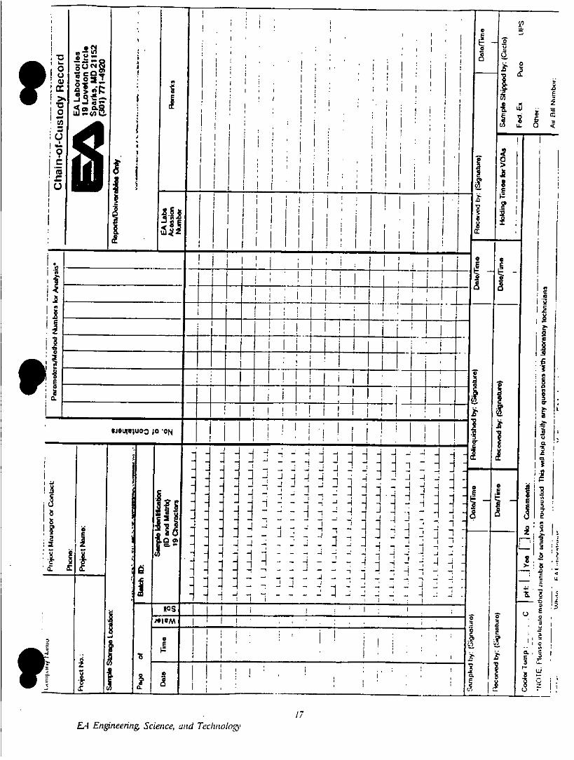
The brass tubes and the sample jars will be securely labeled with the sample number(indicating the stockpile identification and the location of the sample within the stockpile)and the date and time of sample collection. The samples will then be sealed in separateplastic "zip-lock" bags and immediately placed in coolers containing ice for delivery underchain-of-custody to an analytical laboratory (Figure 5). Sampling data and sampledescriptions utilizing the Unified Soil Classification System (USGS) will be logged in fieldnotes by the sampling team.
The brass tubes and the digging and sample collection equipment will be decontaminatedby scrubbing with an Alconox solution and then rinsing with de-ionized water. The samplecollection equipment will be decontaminated between sample locations in order to preventcross-contamination.
5.1.2 Soil Screening Samples' ~~Each of the soil collection sites will be screened directly by testing the air immediately over
IP ~the pile of soil removed from the boring with a direct-reading Foxboro Organic Vapor
16EA Engineering. Scien ce, and Teclhzologv
- I~~~~~~~~~~~~~~~~~~~C
COL,~~~~~~~~~~~~~~~~~~~~~~~~~~~~~~
La (
a:
~~~~~~ ~ ~ ~ J 1 I I. I
E I~~~~~~~~~~~~~~~~~~~~~~~~~~
OM 2~~~~~~~~~~~~~~~~4' ~~~~
17iiiEAEgierigScece -n Teho- *

Analyzer (OVA), which is equipped with a flame ionization detector. The results of thefield screening will be recorded in field notes along with descriptions of the sample sites.
Becau se there may be hydrocarbons present in the pile that will not volatilize readily in thefield conditions, samples will be collected for head-space screening by manually loading soilinto zip-lock bags. The bags will be filled less than 1/4 full and will be heated in sunlightor over an automobile heater to promote volatilization of the hydrocarbons. The screeningwill be conducted by inserting the probe of the OVA into a small opening of the bag afterthe soil has been heated and shaken to encourage volatilization. The soil for the headspacesamples will be retrieved from the piles from positions as close as possible to thecorresponding sample to be submitted for analysis.
5.2. Laboratory QA/QC
Soil samples will be sent to one of three analytical laboratories; Pacific NorthwestEnvironmental Laboratories of Redmond, Washington; Chemical and GeologicalLaboratories of Anchorage, Alaska, or; Northern Testing of Anchorage, Alaska. All threelaboratories are certified by ADEC and have previously submitted their qualityassurance/quality control procedures to the State of Alaska.
EA Engineering. Science, and Technology
6. HEALTH AND SAFETYI ~~Two Site Safety and Health Plans (SSHP) will be required for the two different phases (pre-treatment sampling phase, treatmgnt phase) of the project. The SSHP for the first phaseof the project has been prepared as a separate document entitled 'Site Safety and HealthPlan for Pre-Treatment Sampling of Stockpiled Fuel-Contaminated Soils at Fielson AirForce Base." This SSHP provides hazard information relating to contaminants, utilities, andpotential underground obstacles that may be encountered by field personnel. It alsodescribes safety measures that. will be followed by field personnel to minimize risksassociated with pre-treatment sampling operations, and outlines the environmentalmonitoring tasks that have been established to assess flammability/explosion hazards andworker exposures.
An SSHP for the second phase of the project (treatment and confirmational sampling) willbe developed after results from the first phase have been reported and reviewed, and thefinal treatment unit specifications and siting have been selected. The contents of thisdocument will be similar to those of the first-phase SSHP, but additional hazard and safetyinformation specific to operation of the treatment unit and materials handling will beincluded.
All site workers assigned to this project have completed 40-hour OSH-A training courses inHealth and Safety at Hazardous Waste Sites, as well as OSHA-required 8-hour refresherP ~~courses. The Site Safety and Health Supervisors assigned to the different phases of theproject have completed 8-hour OSHA Health and Safety Supervisor training.
Site workers will sign a review form attached to the SSHP to indicate that they havereviewed the Plan, and that they agree to abide by the safety measures outlined therein. Acopy of the appropriate SSHP will be present on site during working hours.
IP19
EA Engineefing, Science, and Technology

7. SCHEDULEI ~~Field sampling is scheduled to take place July 26-August 2, 1991. Analytical results will bereviewed by August 12, 1991 and submitted to ADEC by August 15, 1991. The soiltreatment subcontract will be issued on or about August 26 and active soil treatment willbegin on about September 16, 1991. Cold weather and/or air quality considerations willlikely require that the operation be shut down for the season at the end of October 1991.
20LA Engieering, Science, and Technology
REFERENCESp ~~Alaska Department of Environmental Conservation. 1991a. Guidance for Storage,Remediation and Disposal bf Petroleum Contaminated Soils.
Alaska Department of Environmental Conservation. 1991b. Instructional Guidance forUsing the Alaska Cleanup Matrix for Regulated USTs.
Alaska Department of Environmental Conservation. 1991c. Interim Guidance for Non-UST Soil Cleanup Levels.
Davis Construction and Engineering. 1990. Specifications for Testing, Excavation, andTemporary Storage of Soils During Dining Hall Construction.
Hinchee. 1990. Notification letter sent to P. McGee, ADEC, 11 May 1990
Keiling, 1991, transmitted letter to P. McGee, Environmental Remedial Projects andProcedures for 1990, undated.
Koenen. 1991. Personal conversation with M.P. Ramey, 7/10/91.
Markey. 1990. Letter to V. Cable, Elmendorf AFB. Dated October 12, 1990.
21F-4 Engineering, Science, and Technology