
FIFTEEN YEARS OF APPLICATIONS IN ITALY: … YEARS OF APPLICATIONS IN ITALY: CASE STUDIES Authors:...
15
FIFTEEN YEARS OF APPLICATIONS IN ITALY: CASE STUDIES Authors: Paolo Casadei, Ph.D., P.E. Consultant Engineer TEC.INN. S.r.l., Technical & Commercial Division Piazza Duomo 17 20121, Milano Italy Phone: (+39) 02- 8900108 Fax: (+39) 02- 45471830 Email: [email protected] Emo Agneloni, P.E. President TEC.INN. S.r.l., Head Quarters Via Y.Gagarin 73 06070, San Mariano - Perugia Italy Phone: (+39) 075- 5170096 Fax: (+39) 075- 5177546 Email: [email protected] About the Authors: Paolo Casadei is a consultant engineer in charge of R&D for TEC.INN. S.r.l. (www.tecinn.com ). He received his PhD in Civil Engineering from the University of Missouri-Rolla, USA. He has been involved in numerous projects involving structural upgrade and rehabilitation of concrete and masonry structures using FRP advanced composite materials as well as full-scale in-situ load testing and structural monitoring. He is a member of ACI Committee 437, Strength Evaluation of Existing Concrete Structures, and ACI Committee 440 (FRP). He is also a member of AICO, Italian Fibers Composites Association for the Construction Industry. Emo Agneloni , entrepreneur, president of TEC.INN. S.r.l. (Innovative Technologies, www.tecinn.com ) founded in 1986. He has more than 20 years experience in the repair and strengthening of concrete and masonry structures, specialized in using extremely innovative technologies and materials to restore, recover, strengthen and protect any type of structures, from infrastructures to historical-artistic-monumental buildings. He is a founding member of AICO, Italian Fibers Composites Association for the Construction Industry.
Transcript of FIFTEEN YEARS OF APPLICATIONS IN ITALY: … YEARS OF APPLICATIONS IN ITALY: CASE STUDIES Authors:...

FIFTEEN YEARS OF APPLICATIONS IN ITALY: CASE STUDIES Authors: Paolo Casadei, Ph.D., P.E. Consultant Engineer TEC.INN. S.r.l., Technical & Commercial Division Piazza Duomo 17 20121, Milano Italy Phone: (+39) 02- 8900108 Fax: (+39) 02- 45471830 Email: [email protected] Emo Agneloni, P.E. President TEC.INN. S.r.l., Head Quarters Via Y.Gagarin 73 06070, San Mariano - Perugia Italy Phone: (+39) 075- 5170096 Fax: (+39) 075- 5177546 Email: [email protected] About the Authors: Paolo Casadei is a consultant engineer in charge of R&D for TEC.INN. S.r.l. (www.tecinn.com). He received his PhD in Civil Engineering from the University of Missouri-Rolla, USA. He has been involved in numerous projects involving structural upgrade and rehabilitation of concrete and masonry structures using FRP advanced composite materials as well as full-scale in-situ load testing and structural monitoring. He is a member of ACI Committee 437, Strength Evaluation of Existing Concrete Structures, and ACI Committee 440 (FRP). He is also a member of AICO, Italian Fibers Composites Association for the Construction Industry. Emo Agneloni, entrepreneur, president of TEC.INN. S.r.l. (Innovative Technologies, www.tecinn.com) founded in 1986. He has more than 20 years experience in the repair and strengthening of concrete and masonry structures, specialized in using extremely innovative technologies and materials to restore, recover, strengthen and protect any type of structures, from infrastructures to historical-artistic-monumental buildings. He is a founding member of AICO, Italian Fibers Composites Association for the Construction Industry.

Abstract: Due to their light weight, high stiffness-to-weight and strength-to-weight ratios, and potentially high resistance to environmental degradation, resulting in lower life-cycle costs, advanced composites materials, commonly known with the acronym FRP, are increasingly being considered for use in civil engineering applications, ranging from the retrofit and rehabilitation of buildings and bridges to the restoration and strengthening of historical-monumental masonry structures. Thanks to the recently published Italian FRP guidelines, CNR-DT 200/2004, by the Italian National Research Council, there has been an increasingly demand of their implementation for general strengthening and retrofitting applications as well as seismic mitigation, being the latter pushed by the new organization of the national territory into a large seismic area with different magnitudes depending on the geographical location. This paper aims to provide a general overview of the Italian state of the art implementation of FRP materials in the last 10 years, through different case studies, ranging from reinforced concrete to masonry and timber structures, on recent and historic buildings and infrastructures, such as the Royal Palace in Milan, Consulta’s Palace in Rome, the arch viaduct on the Flaminia road, the Monterchi’s Bridge and many others. Keywords: Bridges, Buildings, FRP, Historical-Monumental Structures, Masonry Structures, Reinforced Concrete Structures, Retrofitting, Seismic Strengthening. 1 INTRODUCTION
After an initial phase of experimentation and research, validated by extremely positive results, the use of advanced composite materials in the civil industry, is now days a well established reality. Currently the main retrofit and strengthening projects, regard mainly buildings, industries, infrastructures and, particularly in seismic areas, on masonry historical structures.
In the last years, the technological innovation in the aforementioned sector has been characterized by an important acceleration. The boost of such technology started in the 90’s, when innovative fiber materials, thanks to their very competitive weight to strength ratios, high durability and ease of installation, represented the most ideal substitute of the widely applied technique of “Béton Plaque”.
Fiber reinforced polymer (FRP) materials are composite materials consisting of high strength fibers in a polymer matrix. The fibers in an FRP composite are the main load-carrying element and exhibit very high strength and stiffness when pulled in tension. An FRP laminate will typically consist of several million of these thin, thread-like fibers. The polymer matrix (sometimes referred to as the resin) protects the fibers from damage, ensures that the fibers remain aligned, and allows loads to be distributed among many of the individual fibers in the composite. There are a variety of fiber types and resins that may be used to create an FRP composite. Fibers are selected based on the strength, stiffness, and durability required for the specific application, and the resins are selected based on the environment the FRP will be exposed to as well as the method by which the FRP is being manufactured.
Among several possibilities, the fiber types that are typically used in the construction industry are carbon, glass, and aramid. In selecting the type of fiber to be used for an application, there are a few things to consider. Glass FRP is excellent for seismic upgrades where the seismic loads only temporarily engage the FRP. In cases where stresses are sustained in the FRP (such as in bending and shear strengthening), glass FRP should be avoided (or service stresses maintained at a minimum level) because of creep rupture effects. Carbon is much more suitable in these applications. Similarly in exterior applications, carbon FRP will be much more durable. Aramid fibers are indeed mostly used now days in masonry applications to realize connection between the strengthening layer, commonly of carbon or glass fibers, and the main structural members thanks to their better performance towards concentrated shear stresses that make them the most suitable for this type of application.
FRP systems in the civil repair industry are used to strengthen existing structures/infrastructures. Structures may need strengthening due to deterioration, design/construction errors, a change in use or

loading, or for a seismic upgrade. In particular this last issue has become of high priority in Italy and in all seismic countries, where new and updated seismic codes have come into place.
FRP essentially works as reinforcement in concrete/masonry/timber and provides strength where concrete/masonry are weakest – in tension. FRP may be used on beam or slab soffits to provide additional flexural strength, on the sides of beams to provide additional shear strength, or wrapped around columns to provide confinement and additional ductility (a primary concern in seismic upgrades). Among many other applications, concrete and masonry walls may be strengthened to better resist seismic and wind loads, concrete pipes may be lined with FRP to resist higher internal pressures, and silos and tanks may be strengthened to resist higher pressures. On historic structures FRP are mainly used to strengthen masonry domes and vaults providing a link among the several portion of the elements without adding any additional mass and most importantly avoiding the most critical failure modes of such type of structures, contrasting the formation of hinges and retarding/avoiding premature collapse.
It is evident though that the installation of these materials cannot be handed into everybody’s hands: it is of critical importance that experienced and well trained engineers and contractors need to be always hired when dealing with these innovative materials. Nowadays the publication of international guidelines, among which there is also the recently published Italian document published by the National Research Council CNR-DT 200/2004 (also available in English) “Guide for the Design and Construction of Externally Bonded FRP Systems for Strengthening Existing Structures”, makes this sector of the civil industry safer from extemporary designers and contractors. In any case though, managing these materials both on the design as well as installation phase cannot be reduced to simply following a design guide line. A critical role in the field of restoration and consolidation is based on propedeutical non-destructive and static load tests to acquire all the necessary information about the structure, prior the design and the installation of these materials. In order to assure the quality of the execution, non-destructive tests shall also be performed once the job is complete to verify that all critical parameters, such as bond, fiber alignment among the most significative ones, are all within the recommended values. This approach not only allows verifying the quality of the contractor job but in many cases has also been necessary to guarantee the owner of the efficiency of the technology chosen. Many are the jobs where a pilot study has been conducted over a small portion of the structure following this procedure: first a static load test is performed to evaluate the current behavior of the structure under loads (deformations, degrees of fixity, vibrations, strains, etc), then the FRP is installed and finally a last static load test is performed in order to compare the behavior of the structure before and after strengthening. In many cases the direct comparison of the load-vs-deflection curve before and after the FRP installation is the key parameter that validates the technology.
In Italy as well as in many other seismic countries, the use of advanced composite materials for strengthening and retrofitting existing structures has been heavily introduced in the market by recent earthquakes and natural disasters. In particular the earthquake that interested the central Italian regions of Umbria and Marche in 1997-’98 has heavily pushed engineers and contractors on the use of the FRP technology thanks to the aforementioned qualities. In particular, to strengthen structures against seismic/dynamic loads, FRPs are particularly efficient because in front of very performing mechanical properties they have very low weights and consequently they do not add any mass to the structure making them ideal for this type of retrofits.
Nowadays the mainstream market of these materials in Italy is for masonry historical structures where their implementation varies from: Increasing the capacity of panels, arches, or vault; wrapping of columns to enhance their compressive strength and ductility; reducing thrust forces in thrusting structures; transforming non structural members into structural members by increasing their stiffness and strength; strengthening and stiffening horizontal non-thrusting structures; wrapping buildings at floors and roof locations.
TEC.INN. S.r.l., founded in Perugia-Italy in 1986 has been pioneer in Italy in the research, installation and development of the FRP technology with over 1000 retrofit-consolidation-strengthening applications all over Italy and few also abroad, varying from reinforced and prestressed concrete to historical-monumental masonry structures. Specialty contractor on innovative materials,

TEC.INN. S.r.l. is able to offer, in Italy and worldwide, advanced retrofitting and strengthening solutions, using FRP systems and innovative materials, to public and private owners, consulting engineering firms and contractors, starting from in-situ diagnostic phase finalized to support designers of the retrofitting system, till the installation phase and/or knowledge transfer to local contractors of advanced composite FRP technology.
In this paper are presented only few among the many, of the most significative applications on both buildings and infrastructures, with a particular emphasis on the second ones. The applications are divided among buildings and bridges looking at both historical masonry structures as well as reinforced concrete ones. 2 FRP APPLICATIONS ON MONUMENTAL MASONRY AND REINFORCED
CONCRETE STRUCTURES
2.1. FRP retrofitting and consolidation of the “Maggiore Fountain” in Perugia. The “Maggiore Fountain” in Perugia was built and decorated between 1277 and 1278. The fountain
consists of three basins laid one upon the other and on the third bronze basin that was cast by Rosso Padellaio of Perugia, is placed a group of three women. On the other two lower basins there are symbolic bas-reliefs and statues which testify the strength of Perugia at the end of the thirteenth century.
Assonometry view of the basins View of the fountain in the square Detail view of one of the marble panels
Figure 1 – The Maggiore Fountain in Perugia The restoration has brought the artistic work back to its ancient splendor, eliminating all the
invasive and obsolete retrofitting works carried out during the previous restorations. The lower basin in fact has undergone a considerable damage in consequence of very invasive retrofitting works that had caused the crack of the marble panels. Therefore the retrofitting had the aim to strengthen, border and join the marble panels inside the lower basin of the fountain.
The restoration has been preceded by the catalogue of a volume containing all the information – both geometrical and photographic – about each single panel, including the performing of strengthening solution and the suitable experimental not destructive testing (NDT) in order to illustrate the map of cracks before the restoration.
Figure 2 – FRP strengthening of the marble panels of the fountain
The retrofit is mainly subdivided into two stages:
1) Strengthening of each single panel through the application of GFRP strips (unidirectional glass fiber sheets) lengthwise and crosswise to restore the loss of continuity because of the cracks created by changes of temperature, structural settling and unsuitable previous restorations;
2) Joining contiguous marble panels through unidirectional GFRP. GFRP strips have been prearranged in order to respect the original idea of panels not rigidly fixed, so as to avoid, in case of earthquake shocks, a possible falling apart.
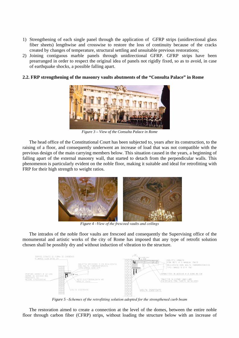
2.2. FRP strengthening of the masonry vaults abutments of the “Consulta Palace” in Rome
Figure 3 – View of the Consulta Palace in Rome
The head office of the Constitutional Court has been subjected to, years after its construction, to the
raising of a floor, and consequently underwent an increase of load that was not compatible with the previous design of the main carrying members below. This situation caused in the years, a beginning of falling apart of the external masonry wall, that started to detach from the perpendicular walls. This phenomenon is particularly evident on the noble floor, making it suitable and ideal for retrofitting with FRP for their high strength to weight ratios.
Figure 4 –View of the frescoed vaults and ceilings
The intrados of the noble floor vaults are frescoed and consequently the Supervising office of the
monumental and artistic works of the city of Rome has imposed that any type of retrofit solution chosen shall be possibly dry and without induction of vibration to the structure.
Figure 5 –Schemes of the retrofitting solution adopted for the strengthened curb beam The restoration aimed to create a connection at the level of the domes, between the entire noble
floor through carbon fiber (CFRP) strips, without loading the structure below with an increase of

masses added by the retrofit. In order to do so, a sort of curb “beam” made by FRP and in composite material has been realized on the extrados of the vaulted ceilings, taking advantage of the masonry tapering in proximity of the vaults moving from one floor to the other.
Strengthening scheme of the vaults Strengthening scheme of the curb beam above the vaults
Figure 6 –View of the frescoed vaults and ceilings The strengthening aimed to restore the continuity to the main load carrying masonry walls and at
the same time to reduce any deformation movements induced by the present attempt of the external walls to fall apart, due to the thrust generated by the loads of the floors above.
2.3. FRP strengthening of the masonry vaults of the “Royal Palace” in Milan.
Figure 7 – View of the Royal Palace in Milano
The structure that characterizes the buildings of “Royal Palace” is very complex and different,
showing the long and difficult evolution that it has undergone dug the centuries with retrofitting jobs and following reconstructions.
“Royal Palace” in fact presents different structural schemes corresponding to different constructive systems and ages.
While the vertical structures basically consist of load bearing, the walls horizontal one presents a remarkable variety of structural systems: we can notice masonry vaults, timber floors with single or double beam layers, steel joists’ floors with masonry vaults insisting on them, floors made by clay bricks and RC joists and reinforced concrete beams even with large spans.
The study of the current state of art and appropriate structural understanding of all its elements represent the main “start” to make the most suitable decisions for each single case.
Consequently a lot of NDT investigations have been done to describe the state of art of the structures, aiming to characterize the units of the building and the static details of each single floor system.
The main NDT campaign consisted of endoscopy tests integrated with sound testing, flat jacks and small localized sample material removal for material characterization.
Where endoscopy could not be used, geo-radar, laser profilometer and thermography has been adopted following the initial phase of knowledge about the structure, the most suitable retrofit solution was chosen.

The structural retrofit aimed to respond to a change of the loading conditions of an entire floor of the Palace, due to a change in destination of use of it.
The overall retrofit job consisted of three main phases.
FRP distribution on the vault and anchors
location at the abutments Detail of the FRP
strengthening of a vault Figure 8 – FRP strengthening of the masonry vaults
The first one consisted of the local realization of members such as staircases or lifts needed to
assure the accessibility of the rooms and the safe standards imposed by current laws. The second one concerned the complete reconstruction of structural elements, above all of floors,
that do not have sufficient static performance nor allow an economic and easy restoration. This was realized by installing glass FRP pultruded profiles on top of the existing timber beams without removing the existing timber joists. The GFRP “I” profiles were bonded on the beam after that it was partially reconstructed, by creating a perfectly horizontal profile with epoxy resins especially design for timber reconstruction.
Finally, the third one, concerned the strengthening of the masonry vaults, that did not present, from the initial state, adequate structural performance according to the new loading scenario, or simply because they needed to be preserved because of their architectonical-monumental value.
2.4.FRP flexural strengthening of a RC beam due to enlargement of a span in an industry factory
(Complastex Industry Factory, Lucca) The building object of the retrofit is an industrial structure consisting of a reinforced concrete (RC)
frame with columns 5,6mt high and 7mt spaced. The beam presents a “L” profile in order to support the precast (PC) “Y” beams (20mt span) supporting the roof; the above-mentioned beams generate a torsion moment over the “L” profile beam.
Figure 9 – The reinforced concrete column to be demolished
A change in the production line of the factory required the demolition of one of the columns
supporting the aforementioned beam.

As a consequence of this demolition the beam changed its static configuration, literally doubling the span and modifying from a continuous beam to a new structural configuration. On the beam insisted a uniform load, transversally asymmetrical, that generated both flexural and torsion moments.
The project aimed to contrast the increase of flexural stresses generated by the double span by installing CFRP sheets to increase the moment capacity. In addition, in order to drastically reduce service deflections, the project consisted of the mechanical lift up of the beam exactly at the location of the existing column. This upward deflection aimed to engage from beginning the CFRP sheets used to strengthen the beam. By doing so, the sheets behaved like if they had been partially prestressed cancelling a portion of the service load insisting on it.
The project has been preceded by NDT in situ campaign, aimed to obtain information about the concrete strength, static performance, compatibility with the strengthening material adopted and finally to determine the conservative status of the substrate where CFRP were about to be bonded.
Since the beam presented overall good condition, the preparation phases simply consisted in cleaning the substrate through hand-brushing followed by a thin leveling of the concrete surface using a tixotropic cement based mortar.
Retrofit phases: 1. installation of a mechanical steel system, anchored to the column;
Figure 10 – Phase 1
2. cut through the column-beam joint to separate them. Following the cut two hydraulic jacks
have been used to lift up the beam; 3. once the beam has been lifted up, it has been securely shored in order to completely
disengage the connection with the column;
Figure 11 – Phase 2-3
4. once the beam has been shored, the strengthening with CFRP has started and, once
terminated, after allowing the resin to cure, the shores have been removed and the CFRP has been immediately engaged permitting the beam to only deform to its initial position (prior to the removal of the column);

Figure 12 – Phase 4
5. finally once the strengthening and shoring have been removed, also the column has been
completely demolished, carefully monitoring that the induced torsion moments would not overstress the beam
Figure 13 – Phase 5
At completion of the retrofit, in situ tests were performed in order to check and verify all the
structural demands and performance.
Figure 14 – View of the column completely isolated from the beam
The sequence of in situ tests has been as follows:
• static load test on the beam after the strengthening; • ultrasound testing on concrete and on the CFRP sheets after the strengthening; • bond tests on the CFRP to verify its adhesion to the substrate; • pull-out test on the concrete of the beam after the strengthening.
The load testing has been realized applying a concentrated force at midspan through a hydraulic jack following a cyclic load test procedure with loading and unloading cycles. Monitoring of the member has been performed through a displacement transducer placed at midspan and two strain gauges installed on the CFRP to monitor their stress.

2.6 FRP Strengthening and confinement of roof conoids of SACMI Industries (Imola) The retrofit realized at the SACMI Industries in Imola concerned the FRP strengthening and the
consolidation of 180 roof conoids.
Figure 15 – Section view of one of the conoids of the SACMI Factory and detail of the strengthening of the corbel reinforced concrete beam.
The main problems faced were essentially two: firstly to respond to a static need of compliance to
the new seismic code (recently introduced Italian code 3274) and of safety consolidation of the clay bricks that were facing the problem of falling over the construction line below, secondly to provide a sufficient crosswise connection among the different adjacent roof conoids, not connected any how at the present state.
One of the conoids at strengthening completed Tension test to verify FRP bonding
Figure 16 – Strengthening of roof conoids using CFRP and GFRP sheets
The strengthening consisted on the application of lengthwise and crosswise GFRP strips carefully bonded on previously leveled substrate using putty resin.
The retrofits realized have avoided and reduced the risk of bricks fall down and guaranteed compliance with increased seismic loads, preceded and followed by several in situ tests aimed to know and verify the quality of the retrofit and strengthening job.
3 FRP APPLICATIONS ON MASONRY AND REINFORCED CONCRETE BRIDGES
3.1 CFRP strengthening of a masonry arch bridge located in San Pietro in Cariano, Verona.
The retrofit concerned the strengthening of a solid brick masonry arch bridge located in San Pietro in Cariano (Verona).
The change of the traffic loads in recent years and the lack of maintenance have caused on the bridge a remarkable crack state needed to be urgently addressed.

Figure 17 – The masonry arch bridge of San Pietro in Cariano
The work sequence has been as follows: first of all before any FRP installation, all cracks have
been filled with tixotropic mortar carefully removing any falling parts of masonry and leveling with mortar. Then the entire soffit of the arch has been hand-blasted to prepare the substrate for an ideal bond. Once this initial phase has been completed the substrate was ready for FRP installation. CFRP sheets have been installed longitudinally and transversally contributing to an overall increase of the arch capacity and to provide a transversal contribution of the entire structure subjected to concentrated loads.
Videoendoscopy test prior strengthening the bridge Monitoring deflections and strains during a
static load test using conventional loaded trucks Figure 18 – NDT testing prior and after FRP strengthening
Before and after strengthening, an exhaustive testing campaign has been conducted, in order to
provide all necessary information to design the CFRP retrofit solution. Firstly laboratory tests have been performed on samples for material characterization. Then on site
tests, such videoendoscopy and thermography have been conducted to evaluate the crack state and overall structure.
Once the FRP installation was completed, pull-off tests were conducted to evaluate bond strength with the substrate.
Finally in situ load tests using preloaded trucks carefully positioned on the roadway simulating the most possible loading conditions have been performed before and after strengthening to determine structural improvement. Vertical movements of the bridge and strain deformations of the CFRP have been monitored, demonstrating the success of the strengthening.
3.2 CFRP confinement of the degraded RC piers of the viaduct along the historic S.S. Flaminia
road near Spoleto (Perugia). The restoration concerns the recovery, retrofit and strengthening of the reinforced concrete
members of a viaduct, property of ANAS (Italian National Road Board), located at the Km. 112+300 of the Flaminia National road n.3, in the outskirts of Spoleto.
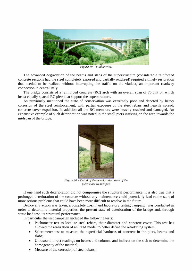
Figure 19 – Viaduct view
The advanced degradation of the beams and slabs of the superstructure (considerable reinforced
concrete sections had the steel completely exposed and partially oxidized) required a timely restoration that needed to be realized without interrupting the traffic on the viaduct, an important roadway connection in central Italy.
The bridge consists of a reinforced concrete (RC) arch with an overall span of 75.5mt on which insist equally spaced RC piers that support the superstructure.
As previously mentioned the state of conservation was extremely poor and denoted by heavy corrosion of the steel reinforcement, with partial exposure of the steel rebars and heavily spread, concrete cover expulsion. In addition all the RC members were heavily cracked and damaged. An exhaustive example of such deterioration was noted in the small piers insisting on the arch towards the midspan of the bridge.
Figure 20 – Detail of the deterioration state of the
piers close to midspan If one hand such deterioration did not compromise the structural performance, it is also true that a
prolonged deterioration of the concrete without any maintenance could potentially lead to the start of more serious problems that could have been more difficult to resolve in the future.
Before any action was taken, a complete in-situ and laboratory testing campaign was conducted in order to determine material properties, the present state of deterioration of the bridge and, through static load test, its structural performance.
In particular the test campaign included the following tests: • Pachometer test to localize steel rebars, their diameter and concrete cover. This test has
allowed the realization of an FEM model to better define the retrofitting system; • Sclerometer test to measure the superficial hardness of concrete in the piers, beams and
slabs; • Ultrasound direct readings on beams and columns and indirect on the slab to determine the
homogeneity of the material; • Measure of the corrosion of steel rebars;

• Pull-out tests on beams, piers and slab; • Windsor probe test on beams, piers and slab; • Laboratory tests to determine compression and tensile strength of concrete from cores
obtained from slab, beam and piers. The initial static load test, to determine structural performance prior to any
strengthening/retrofitting application, has been performed using conventional loaded trucks, carefully positioned on the roadway in order to cause the most critical loading configuration and evaluate the superstructure performance. Using inclinometers, placed at predetermined locations, it has been possible, through numerical derivation, to obtain the experimental deformation and backwards the degree of fixity of each span of the bridge. Test results showed that, even if the deterioration of the structure was very diffused, the structure was yet behaving in a proper way. Consequently any retrofit solution adopted was more likely to prevent and upgrade to higher loads the structure rather than solving any present problem apart from a deterioration issue already explained.
Consequently the proposed design consisted in retrofitting any deteriorated sections (focusing in particular on the columns) by firstly removing any concrete spalling and passivating all the exposed rebars; secondly the section was recast with appropriate high strength cement based mortars and lastly, were necessary, the strengthening of the section using FRP. The use of FRP has regarded solely column confinement. All chosen piers have been wrapped with CFRP sheets along their entire length providing the requested increase in compressive strength.
Figure 21 – A deteriorated reinforced concrete
pier, before and after CFRP wrapping
3.3 CFRP strengthening of a reinforced concrete bridge following a roadway widening, located in Monterchi (Arezzo). This strengthening job regards the enlargement of a reinforced concrete arch bridge located over
the Cerfone creek, near Pantaneto di Lippiano a small village near Monterchi in the city district of Arezzo.
Figure 22 – View of the bridge prior to roadway widening

The main carrying structure is an arch bridge spanning 22mt supporting the roadway. Due to a necessary enlargement of the carriage, the structure was found not adequate to support the new dead and live loads that the redesigned structure was going to receive. In addition, on both sides of the roadway the project expected to build a pathway overhanging on both sides.
The design consisted in removing the existing pavement and placing above it precast “predalles” slabs supported by cantilever beams on both sides with variable section. On top of this a new RC slab was going to be cast to create continuity and assure that all the new members would have contributed to the new loads. Consequently prior to any new construction it has been found necessary to strengthen the existing arch bridge by mean of CFRP sheets installed along the entire length of the intrados as shown in the figure. By doing so, the FRP sheets have been solicited by the installation of the new elements (dead weight solely) prior to receiving any further stresses due to increase live loads. By doing so, FRPs have contributed not only to support new live loads, but also to the new dead loads caused by the roadway enlargement.
Figure 23 – Retrofitting of the arch soffit using CFRP sheets
In order to define the most appropriate amount of strengthening material needed for the structure to
support both dead and live loads, a detail testing campaign has been conducted. In this case it has been particularly important the static load test that has allowed calibrating a FEM model that was afterwards used to model the new enlarged structure and live loads. The FEM model was produced in Algor and considered the material properties as well as new geometries of all the members.
Figure 24 – Algor FEM model
From the initial model of the existing structure has then been possible to design one of the enlarged
and strengthened structure in order to predict its performance. The FEM model has so allowed the design of the strengthening solution using CFRP sheets with an elevated accuracy as witnessed afterwards by the perfect agreement of the structural behavior under static load test and the one predicted by the model.
CFRP sheets have been installed longitudinally and transversally: in the longitudinal direction three layers of carbon fibers have been installed while transversally has been sufficient only a single layer.
Once the installation has been completed, the strengthening has been verified by ultrasound and pull-off tests to validate bond performance and assuring the quality of the job.

Finally, a static and dynamic load test has been performed on the structure using conventional loaded trucks. The loads imposed were equivalent to the maximum allowed design loads. The bridge performed extremely well and the FEM model predicted accurately the deformations and the stresses in the FRP as confirmed by the strain gauges readings.
4 CONCLUSIONS
The reported case studies have shown the large field of possible cases where FRP have been largely introduced and successfully applied. In recent years thanks to the introduction of national as well as international guidelines, that not only regulated the analytical design of section strengthened with these materials, but also their installation, they have even further disseminated their use.
Now days FRP have entered massively the construction industry and we should expect that in recent years even more projects will involve their use, not only for retrofitting and strengthening existing structures, but also for designing new ones. Relying on experienced contractors and engineers remains though the key issue for a continuous success of this industry. REFERENCES [1] TEC.INN. S.r.l., “Innovative Technologies” San Mariano-Perugia, Italy, www.tecinn.com. [2] CNR-DT 200/2004, 2004: ”Istruzioni per la Progettazione, l’Esecuzione e il Controllo di
Interventi di Consolidamento Statico mediante l’utilizzo di Compositi Fibrorinforzati” Published by the National Research Council (CNR), Roma, pp. 164 (also available in english).


![Casadei, Marco; Ren, Xinguo; Rinke, Patrick; Rubio, Angel ...CASADEI, REN, RINKE, RUBIO, AND SCHEFFLER PHYSICAL REVIEW B 93, 075153 (2016) FIG. 1. Experimental phase diagram [6,24]](https://static.fdocuments.us/doc/165x107/6108a49b4ebb3b55d6498acc/casadei-marco-ren-xinguo-rinke-patrick-rubio-angel-casadei-ren-rinke.jpg)


