
Fieseler Fi 156 Storch - BigPlanesbigplanes.nl/contents/en-uk/Storch-book.pdf · Fieseler Fi 156...
8
AILERON FLAP AILERON 30mm FLAP 20mm 20mm Side View Top View 90mm 2 Plastic tube (3x30mm) Plastic tube (3x30mm) 25mm 11mm 3mm 25mm 3mm Centre of Gravity. Adjustment. Top view 25mm 25mm RUDDER Side View Top view Position for right diagram. ELEVATOR Side View 25mm 25mm Adjustment. Adjustment. Drill holes to appropriate position in the fairing of the cowl and epoxy the wood dowel in them. Drill holes to the relevant position in the cowl and epoxy the cowl fairing to the cowl as below. 74 75 78 76 77 14 73 Specification: Length :1614 mm(63.5") Wing Span :2362 mm(93") Wing Area :61.68 sq. dm 6.64 sq. ft Wing Loading :116.7 g/sq. dm 38.3 oz/sq. ft Flying Weight :7.2 kg(15.8 lbs) Radio :6ch&7servos Engine :120 4-cycle Fieseler Fi 156 Storch SAFETY PRECAUTIONS INSTRUCTION MANUAL First-time builders should seek advice from people having building experience.If misused or abused,it can cause serious bodily injury and damage to property. Fly only in open areas and preferably at a dedicated R/C flying site. We suggest having a qualified instructor carefully inspect your airplane before its first flight.Please carefully read and follow all instructions included with this airplane,your radio control system and any other components purchased separately. (The people under 18 years old is forbidden from flying this model) This R/C airplane is not a toy!
Transcript of Fieseler Fi 156 Storch - BigPlanesbigplanes.nl/contents/en-uk/Storch-book.pdf · Fieseler Fi 156...

AILERON
FLAPAILERON
30mm
FLAP
20mm20mm
Side View
Top View
90mm
2Plastic tube (3x30mm)
Plastic tube (3x30mm)
25mm 11mm
3mm
25mm3mm
Centre of Gravity.
Adjustment.
Top view
25mm
25mm
RUDDER
Side View
Top view
Position forright diagram.
ELEVATOR
Side View
25mm25mm
Adjustment.
Adjustment.
Drill holes to appropriate position in the fairing of the cowl and epoxy the wood dowel in them.
Drill holes to the relevant position in the cowl and epoxy the cowl fairing to the cowl as below.74
75 78
76
77
14
73
Specification:Length :1614 mm(63.5")Wing Span :2362 mm(93")Wing Area :61.68 sq. dm 6.64 sq. ftWing Loading :116.7 g/sq. dm 38.3 oz/sq. ftFlying Weight :7.2 kg(15.8 lbs)Radio :6ch&7servosEngine :120 4-cycle
Fieseler Fi 156 Storch
SAFETY PRECAUTIONS
INSTRUCTION MANUAL
First-time builders should seek advice from people having building experience.If misused or abused,it can cause serious bodily injury and damage to property.Fly only in open areas and preferably at a dedicated R/C flying site.We suggest having a qualified instructor carefully inspect your airplane before its first flight.Please carefully read and follow all instructions included with this airplane,your radio control system and any other components purchased separately.
(The people under 18 years old is forbidden from flying this model)This R/C airplane is not a toy!

4-cycle .120
15″X7
6
76
6
6 channel radio for aiplane is highly recommended for this model.
9 Optional parts: rubber wheel with metal hub.
Spinner nut
We strongly recommen you use the thread lock for all the screws when you build your model.
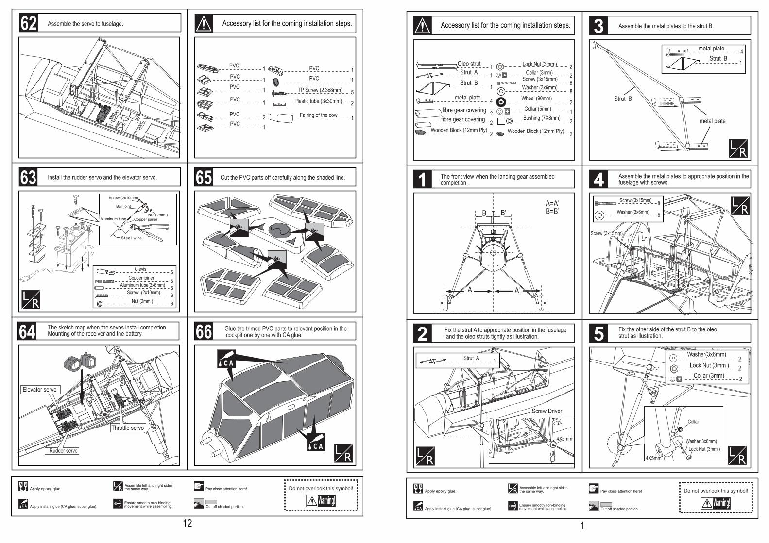
Assemble the cockpit to the fuselage with screw.
Glue the trimed PVC parts to the relevant position in the fuselage one by one carefully with CA glue.
Screw Driver
Assemble the wing to the fuselage until it get to the rightposition as the referent illustration below.
Trim small holes to relevant position in the cockpit for fixing the wings.
A A’
A = A 'B = B '
B B '
Epoxy plies inside the fuselage under the cowing and mount the cowing with TP screw as illustration.
5TP Screw (2.3x8mm)
1.5mm
Assemble the cowling.Trim holes in the cowl for the engine muffler.
TP Screw (2.3x8mm)
75mm
Trim this PVC parts carefully along the shaded line and glue it to appropriate position on the fuselage as illustration.
68
67
13
71
69 72
70
2Plastic tube (3x30mm)
1Fairing of the cowl
Assemble the servo to fuselage.
Steel wire
Copper joinerAluminum tube Nut (2mm )
Screw (2x10mm)
Ball joint
6
66
ClevisCopper joiner
Aluminum tube(3x6mm)
66
Screw (2x10mm) Nut (2mm )
Install the rudder servo and the elevator servo.
Throttle servo
Elevator servo
Mounting of the receiver and the battery.The sketch map when the sevos install completion.
Rudder servo
5TP Screw (2.3x8mm)
PVC
PVC 1
1PVC 1PVC 1
PVC 2PVC 1
PVC 1PVC 1
Cut the PVC parts off carefully along the shaded line.
Glue the trimed PVC parts to relevant position in the cockpit one by one with CA glue.64
63 65
66
12
62 Accessory list for the coming installation steps.
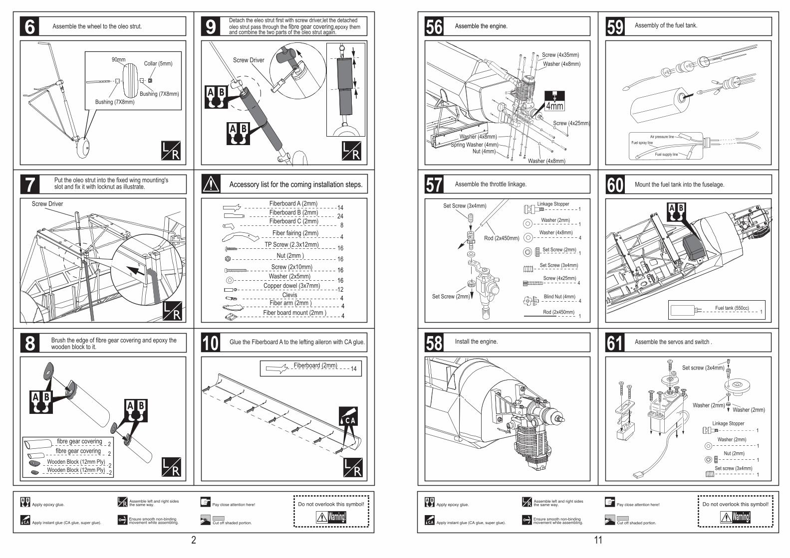
Collar
Lock Nut (3mm )Washer(3x6mm)
22
Washer(3x6mm)Lock Nut (3mm )
2Collar (3mm)
A
B
A’
B’A=A’B=B’
2
21Collar (5mm)
Wheel (90mm)
4X5mm
4X5mm
Washer (3x6mm) 8
8Screw (3x15mm)
Screw (3x15mm)
Washer (3x6mm) 88
Screw (3x15mm)
2Lock Nut (3mm )
2Collar (3mm)
Bushing (7X8mm)
11
1
Oleo strutStrut AStrut B
4metal plate
4metal plate
Wooden Block (12mm Ply) Wooden Block (12mm Ply)2 2
2fibre gear covering
2fibre gear covering
1Strut A
Strut B
1Strut B
The front view when the landing gear assembled completion.
Fix the strut A to appropriate position in the fuselage and the oleo struts tightly as illustration.
Assemble the metal plates to the strut B.
Assemble the metal plates to appropriate position in the fuselage with screws.
Screw Driver
metal plate
Fix the other side of the strut B to the oleo strut as illustration.
1
2
3
4
5
1
Accessory list for the coming installation steps.
1424
8
4
Fiberboard A (2mm)
Fiberboard C (2mm)Fiberboard B (2mm)
Fiber fairing (2mm)
14Fiberboard (2mm)
1616 Screw (2x10mm)
Washer (2x5mm) 16Copper dowel (3x7mm) 12
Nut (2mm )
4Clevis
16TP Screw (2.3x12mm)
44
Fiber arm (2mm )Fiber board mount (2mm )
D
Screw Driver
Bushing (7X8mm)Bushing (7X8mm)
Collar (5mm)90mm Screw Driver
Wooden Block (12mm Ply) Wooden Block (12mm Ply)
22
2fibre gear covering
2fibre gear covering
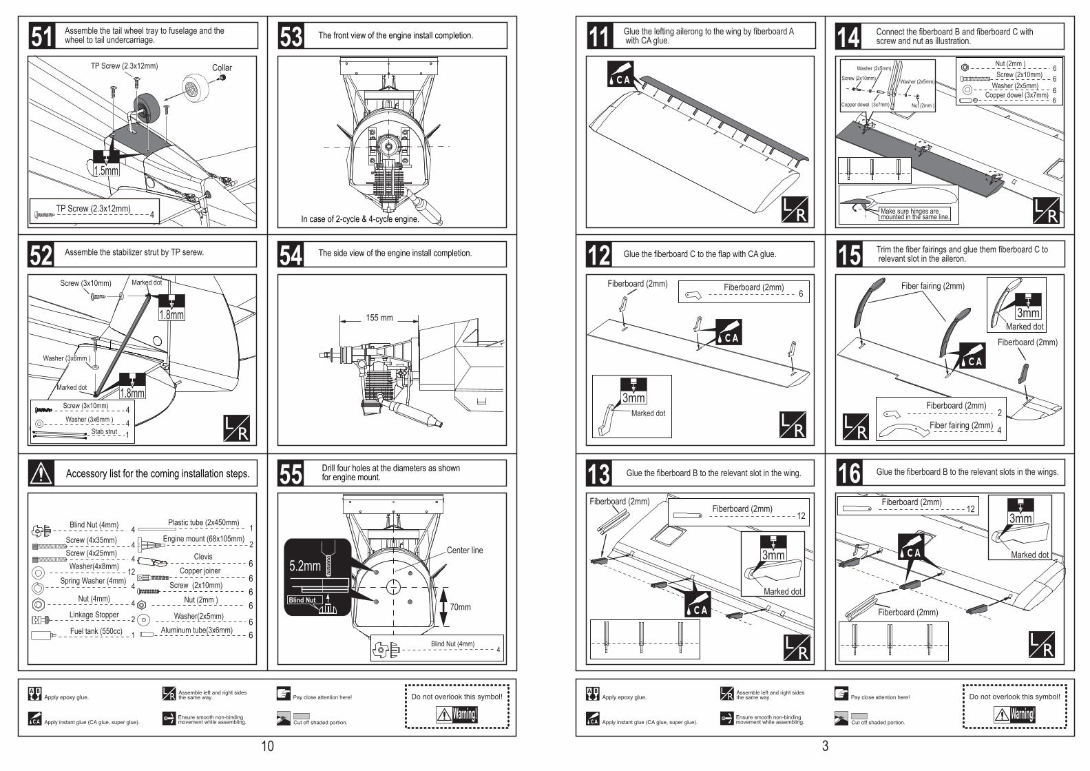
Assemble the wheel to the oleo strut.
Brush the edge of fibre gear covering and epoxy the wooden block to it.
Detach the eleo strut first with screw driver,let the detached oleo strut pass through the fibre gear covering,epoxy them and combine the two parts of the oleo strut again.
Glue the Fiberboard A to the lefting aileron with CA glue.
Put the oleo strut into the fixed wing mounting's slot and fix it with locknut as illustrate.
6
7
8
9
10
2
Accessory list for the coming installation steps.
Linkage Stopper
Washer (2mm)
Washer (2mm)
Nut (2mm)
Set screw (3x4mm)
Washer (2mm)
Set screw (3x4mm)
1
1
1
1
Assemble the servos and switch .
Set Screw (3x4mm)
Set Screw (2mm)
Rod (2x450mm)
Set Screw (2mm)
Washer (2mm)
Linkage Stopper1
1
1
1
4
4
Washer (4x8mm)4
Rod (2x450mm)
Blind Nut (4mm)
Screw (4x25mm)
Set Screw (3x4mm)
Washer (4x8mm)
Washer (4x8mm)
Screw (4x35mm)
Washer (4x8mm)
Screw (4x25mm)
Nut (4mm)Spring Washer (4mm)
4mm
Assemble the engine.
Assemble the throttle linkage.
Fuel supply line
Fuel spray lineAir pressure line
Assembly of the fuel tank.
Install the engine.
Fuel tank (550cc)1
Mount the fuel tank into the fuselage.57
58
59
61
60
11
56
Drill four holes at the diameters as shown for engine mount.
5.2mm
Blind Nut
4Blind Nut (4mm)
Collar TP Screw (2.3x12mm)
4TP Screw (2.3x12mm)
1.5mm
In case of 2-cycle & 4-cycle engine.
4Blind Nut (4mm) 1Engine mount (68x105mm)
Linkage Stopper4
4
12
4
Washer(4x8mm)
Screw (4x35mm)
Spring Washer (4mm)
Nut (4mm)
2
4Screw (4x25mm)
2
Plastic tube (2x450mm)
Fuel tank (550cc) 1
The front view of the engine install completion.
155 mm
The side view of the engine install completion.
66
ClevisCopper joiner
66
Screw (2x10mm)
Nut (2mm )
6Washer(2x5mm)
6Aluminum tube(3x6mm)
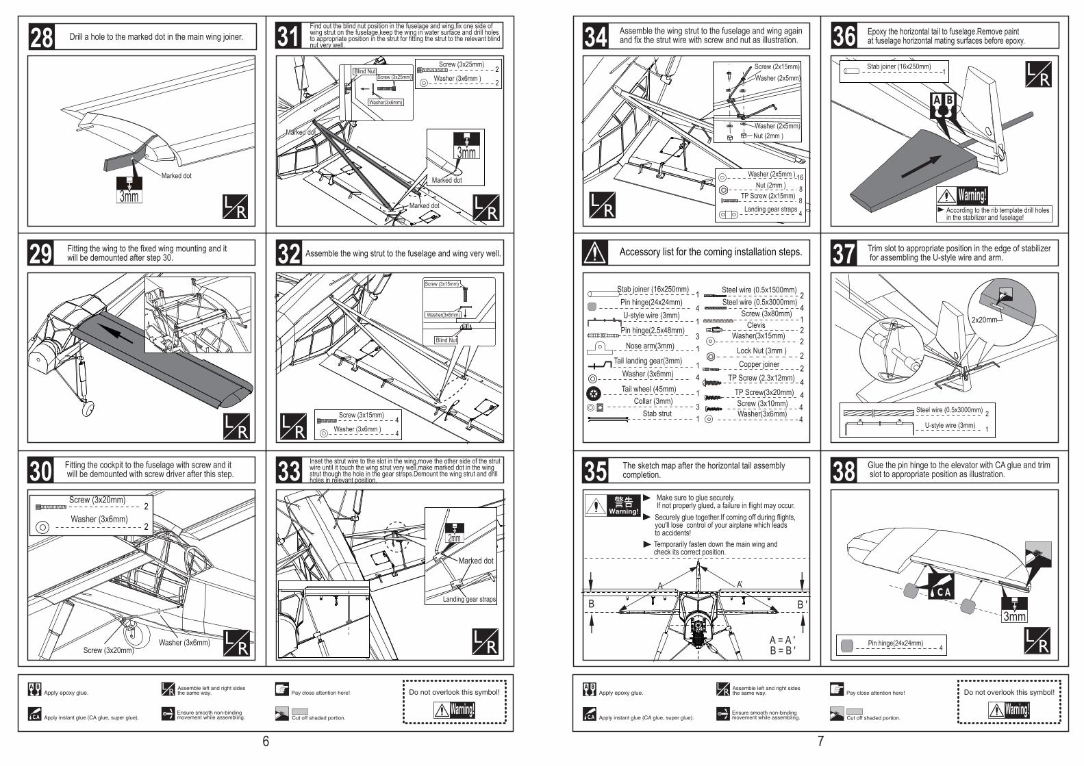
Assemble the tail wheel tray to fuselage and the wheel to tail undercarriage.
Marked dot
Marked dot
Assemble the stabilizer strut by TP serew.
4Screw (3x10mm)
4 Washer (3x6mm )
1Stab strut
1.8mm
1.8mm
Screw (3x10mm)
Washer (3x6mm )
70mm
Center line
52
53
54
55
10
51
Accessory list for the coming installation steps.
6Fiberboard (2mm)Fiberboard (2mm)
12Fiberboard (2mm) 12
Fiberboard (2mm)
2Fiberboard (2mm)
4
Fiber fairing (2mm)
Fiber fairing (2mm)
Fiberboard (2mm)
Fiberboard (2mm)
Fiberboard (2mm)
3mmMarked dot
Marked dot
3mm
Washer (2x5mm)
Washer (2x5mm)
Screw (2x10mm)
Copper dowel (3x7mm) Nut (2mm )
66 Screw (2x10mm)
Washer (2x5mm) 6Copper dowel (3x7mm)6
Nut (2mm )
Make sure hinges are mounted in the same line.
Glue the lefting ailerong to the wing by fiberboard A with CA glue.
Glue the fiberboard C to the flap with CA glue.
Glue the fiberboard B to the relevant slot in the wing.
Connect the fiberboard B and fiberboard C with screw and nut as illustration.
Trim the fiber fairings and glue them fiberboard C to relevant slot in the aileron.
Glue the fiberboard B to the relevant slots in the wings.
Marked dot3mm
Marked dot
3mm
12
13
15
16
11
3
Accessory list for the coming installation steps.
14

4
4
Fiber arm (2mm )
Fiber board mount (2mm )Make sure hinges are mounted in the same line.
1.5mm
TP Screw (2.3x12mm)
TP Screw (2.3x12mm)
8TP Screw (2.3x12mm)
16TP Screw (2.3x12mm)
TP Screw (2.3x12mm)
1.5mm
Install the servo as the illustration below
Retainer Rod (2x300mm)
Install the nylon control horn and connect the linkage.
Ball joint
Lock Nut (2mm )
Fiber arm (2mm )
Fiber board mount (2mm )
Screw (2x10mm)
Copper ball (2mm )Washer (2x5mm)
Washer (2x5mm)
Screw (2x10mm)
Copper dowel (3x7mm) Nut (2mm )
66 Screw (2x10mm)
Washer (2x5mm) 6Copper dowel (3x7mm)6
Nut (2mm )
4Clevis
44
Screw (2x10mm) Nut (2mm )
4Washer(2x5mm)
Washer(2x5mm)
Connect the fiberboard B and fiber fairing with screw and nut as illustration.
Epoxy the fiber arm to the slot in the fiber board mount.
Assemble the fiber board mount to appropriate position in the aileron with TP screw and epoxy.
Secure the servo,connect the linkage of the servo and the fiber arm.
1.5mm
18
19
20
21
17
4
22
Elevator wire
Tail wheel wire Rudder wire
1mm
Rudder
Tailing edge
Cut away the rubber tube whenthe epoxy glue dried.
Make sure they are inthe right position whileinstalling.
Keep some space about 1mm width between the tailing edge and the rudder.
3mm
15mm
2.5mm
Drill hols to appropriate position in the vertical tailand epoxy the rudder to the vertical tail steadily.
Washer(3x15mm)Screw (3x80mm)
Lock Nut (3mm )Clevis
Aluminum tube
Stee l w i re
2Steel wire (0.5x1200mm)
222
ClevisWasher(3x15mm)Lock Nut (3mm )
1Screw (3x80mm)2Copper joiner
The sketch map after the rudder shaft assemble finished.
Drill a hole to appropriate position in the rudder as illustration.
The sketch map of the linkage for the rudder and the tail gear.
The sketch map of the linkages in the fuselage.
46
45
47 50
49
48
9

4Blind Nut (4mm)
1Engine mount (68x105mm)
Linkage Stopper4
4
12
4
Washer(4x8mm)
Screw (4x35mm)
Spring Washer (4mm)
Nut (4mm)
2
4Screw (4x25mm)
2
Plastic tube (2x500mm)
Fuel tank (550cc) 1
1Clevis
22
Steel wire (0.5x1500mm)Fiberglass pushrod(3x775mm)
2Plastic tube(3x50mm)
11
11
1
ClevisRetainer
Screw (3x35mm)Washer(3x15mm)
1Washer(3x15mm)Lock Nut (3mm )
22
ClevisCopper joiner
22
Screw (2x10mm) Nut (2mm )
2Washer(2x5mm)
4TP Screw (2.3x12mm)Ply (15x15x3mm) 4
1Nose arm(3mm)
Collar (3mm) 31
1Tail landing gear(3mm)
Tail wheel (45mm)TP Screw(3x20mm)Washer (3x6mm)
44
4TP Screw (2.3x12mm)
4Steel wire (0.5x3000mm)
222
ClevisWasher(3x15mm)Lock Nut (3mm )
1Screw (3x80mm)
2Copper joiner
2Steel wire (0.5x3000mm)
Pin hinge 3Make sure hinges are mounted in the same line.
40mm
55mm55mm
2.5mm
Epoxy pin hinges to rudder.
1mm
Elevator
Make sure they are inthe right position whileinstalling.
Trailing edge
Keep some space about 1mm width between the elevator and horizontal tail edge.
Securely glue together. If coming off during flights, you 'lllose control of your airplane which leads to accidents!
Glue the elevator to the stabilizer by CA and epoxy.
Collar Tail landing gear
Collar
Collar
TP Screw(3x20mm)
TP Screw(3x20mm)
Washer (3x6mm)
44
The sketch map when assemble the tail landing gear to the wheel steeling mount.
Assemble the wheel steeling mounts to relevantposition in the former of tail gear.
The sketch map when tail wheel assemble completion.
Cut off the suplus parts of the tube for fit the arm well.
Take care not let the tubetouch the arm .
40
41
40
44
8
42
43
39
Accessory list for the coming installation steps.
2Positioning pin (3x90mm)1
Fiber main wing joiner(6mm)
2Screw (3x20mm)
3mm
Rib template (2mm ply)
Positioning pin (3x90mm)
1
2Rib template (2mm ply)
Rib template (2mm ply)
35mm
3mm
1Rib template (2mm ply)
Positioning pin (3x90mm)
Landing gear straps 4
4Screw (3x15mm)
Wing strut 1
Strut wire 1
8Washer(3x6mm)
8TP Screw (2x15mm)
168Nut (2mm )
Washer (2x5mm )
2Screw (3x25mm)
1Fiber main wing joiner(6mm)
A
B B‘
A‘
A = A 'B = B '
Make sure to glue securely.If not properly glued, a failure in flight may occur.
Temporarily fasten down the main wing and check its correct position.
The surface of the top wings should be in one plan.
Securely glue together.If coming off during flights,you'll lose control of your airplane which leads to accidents!
The sketch map after the wings assembly completion.
Epoxy the positioning pin and the wing joiner to the wing tightly..
Assemble the wing to the fixed wing mount until it fit very well and mark in the main wing joiner through the hole in the mount with red mark.
According to the rib template drill a hole to appropiate position in the wing root.
According to the rib template open a slot in the cockpit as illustration for draging the servo lines..23
24
26
27
5
Accessory list for the coming installation steps. 25
Marked dot
Marked dot
Blind Nut
Blind Nut
Washer(3x6mm)
Marked dot
3mm
Screw (3x25mm)
Screw (3x15mm)
Washer(3x6mm)
Marked dot
Landing gear straps
2mm
2Screw (3x25mm)
2 Washer (3x6mm )
4Screw (3x15mm)
4 Washer (3x6mm )
Assemble the wing strut to the fuselage and wing very well.
Inset the strut wire to the slot in the wing,move the other side of the strut wire until it touch the wing strut very well,make marked dot in the wing strut though the hole in the gear straps.Demount the wing strut and drill holes in relevant position.
Fitting the cockpit to the fuselage with screw and it will be demounted with screw driver after this step.
Fitting the wing to the fixed wing mounting and it will be demounted after step 30.
3mmMarked dot
Drill a hole to the marked dot in the main wing joiner.
Washer (3x6mm)Screw (3x20mm)
Washer (3x6mm)2
2Screw (3x20mm)
Find out the blind nut position in the fuselage and wing,fix one side of wing strut on the fuselage,keep the wing in water surface and drill holes to appropriate position in the strut for fitting the strut to the relevant blind nut very well.
29
30
32
31
33
6
28Screw (2x15mm)
Nut (2mm )Washer (2x5mm)
Washer (2x5mm)
Landing gear straps 4
8TP Screw (2x15mm)
168Nut (2mm )
Washer (2x5mm )
Assemble the wing strut to the fuselage and wing again and fix the strut wire with screw and nut as illustration.
1U-style wire (3mm)
3Pin hinge(2.5x48mm)
1Stab joiner (16x250mm)
4Pin hinge(24x24mm)
According to the rib template drill holes in the stabilizer and fuselage!
Epoxy the horizontal tail to fuselage.Remove paint at fuselage horizontal mating surfaces before epoxy.
1Stab joiner (16x250mm)
Make sure to glue securely.If not properly glued, a failure in flight may occur.
Temporarily fasten down the main wing and check its correct position.
Securely glue together.If coming off during flights,you'll lose control of your airplane which leads to accidents!
The sketch map after the horizontal tail assembly completion.
A A’
A = A 'B = B '
B B '
1Nose arm(3mm)
Collar (3mm)31
1Tail landing gear(3mm)
Tail wheel (45mm) TP Screw(3x20mm)
Washer (3x6mm)
4
4 4TP Screw (2.3x12mm)
4Steel wire (0.5x3000mm)
2Steel wire (0.5x1500mm)
222
ClevisWasher(3x15mm)
Lock Nut (3mm )
1Screw (3x80mm)
2Copper joiner
Stab strut 14Screw (3x10mm)
4Washer(3x6mm)
2x20mm
4Pin hinge(24x24mm)
3mm
1U-style wire (3mm)2Steel wire (0.5x3000mm)
Trim slot to appropriate position in the edge of stabilizer for assembling the U-style wire and arm.
Glue the pin hinge to the elevator with CA glue and trim slot to appropriate position as illustration.
34
35
37
7
38
36
Accessory list for the coming installation steps.


![Frank Marrero · 2021. 3. 19. · Fieseler Storch First B-29 Raid on Tokyo USA $3.95 718916 48130 AirAGE CANADA $4.95 48113] Editorial Redefining the Third Dimension et's talk about](https://static.fdocuments.us/doc/165x107/61357bf60ad5d20676476842/frank-marrero-2021-3-19-fieseler-storch-first-b-29-raid-on-tokyo-usa-395.jpg)


