Field Testing Advanced Geothermal Turbodrill (AGT)/67531/metadc684951/m2/1/high...Field Testing...
26
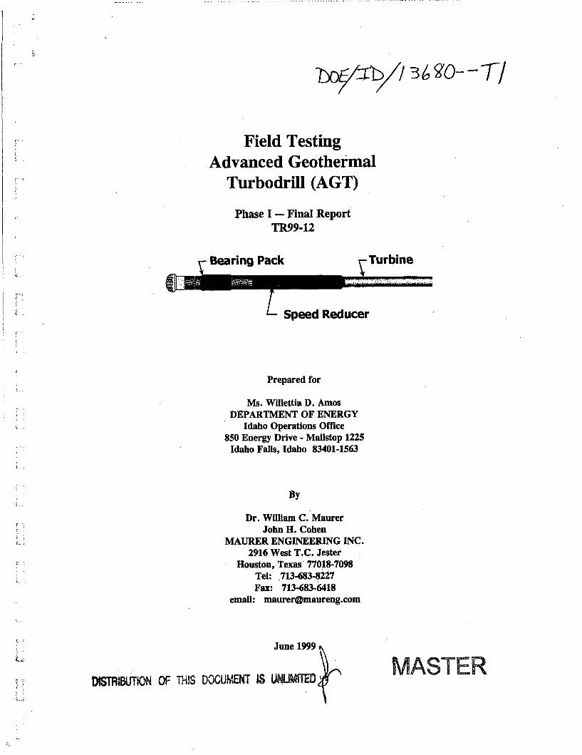
- ... .. . . . .. -- Field Testing Advanced Geothermal Turbodrill (AGT) Phase I - Find Report TR99-12 Bearing Pack Turbine Speed Reducer Prepared for I ?: i I 1'. i Ms. Willettia D. Amos DEPARTMENT OF ENERGY Idaho Operations Office 850 Energy Drive - Mailstop 1225 Idaho Falls, Idaho 83401-1563 Dr. William C. Maurer John H. Cohen MAURER ENGINEERING INC. 2916 West T.C. Jester Houston, Texas 77018-7098 Tel: 713-683-8227 email: [email protected] Fax: 713-683-6418
Transcript of Field Testing Advanced Geothermal Turbodrill (AGT)/67531/metadc684951/m2/1/high...Field Testing...
- ... .. . . . .. - -
Field Testing Advanced Geothermal
Turbodrill (AGT)
Phase I - Find Report TR99-12
Bearing Pack Turbine
Speed Reducer
Prepared for
I
? :
i I
1'. i
Ms. Willettia D. Amos DEPARTMENT OF ENERGY
Idaho Operations Office 850 Energy Drive - Mailstop 1225
Idaho Falls, Idaho 83401-1563
Dr. William C. Maurer John H. Cohen
MAURER ENGINEERING INC. 2916 West T.C. Jester
Houston, Texas 77018-7098 Tel: 713-683-8227
email: [email protected] Fax: 713-683-6418
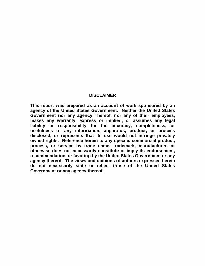
DISCLAIMER
This report was prepared as an account of work sponsored by an agency of the United States Government. Neither the United States Government nor any agency Thereof, nor any of their employees, makes any warranty, express or implied, or assumes any legal liability or responsibility for the accuracy, completeness, or usefulness of any information, apparatus, product, or process disclosed, or represents that its use would not infringe privately owned rights. Reference herein to any specific commercial product, process, or service by trade name, trademark, manufacturer, or otherwise does not necessarily constitute or imply its endorsement, recommendation, or favoring by the United States Government or any agency thereof. The views and opinions of authors expressed herein do not necessarily state or reflect those of the United States Government or any agency thereof.

DISCLAIMER Portions of this document may be illegible in electronic image products. Images are produced from the best available original document.
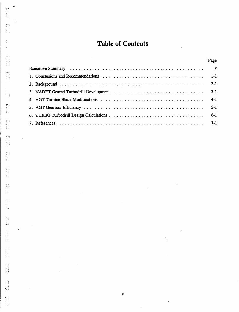
Table of Contents
Page
ExecutiveSummary . . . . . . . . . . . . . . . . . . . . . . . . . . . . . . . . . . . . . . . . . . . . . . . . . V
1 . Conclusions and Recommendations . . . . . . . . . . . . . . . . . . . . . . . . . . . . . . . . . . . . . . 1-1
2 . Background . . . . . . . . . . . . . . . . . . . . . . . . . . . . . . . . . . . . . . . . . . . . . . . . . . . . . 2-1
3 . NADET Geared Turbodrill Development . . . . . . . . . . . . . . . . . . . . . . . . . . . . . . . . . 3-1
4 . AGT Turbine Blade Modifications . . . . . . . . . . . . . . . . . . . . . . . . . . . . . . . . . . . . . . 4-1
5 . AGT Gearbox Efficiency . . . . . . . . . . . . . . . . . . . . . . . . . . . . . . . . . . . . . . . . . . . . 5-1
6 . TURBO Turbodrill Design Calculations . . . . . . . . . . . . . . . . . . . . . . . . . . . . . . . . . . . 6-1
7 . References . . . . . . . . . . . . . . . . . . . . . . . . . . . . . . . . . . . . . . . . . . . . . . . . . . . . . 7-1
ii
Executive Summary
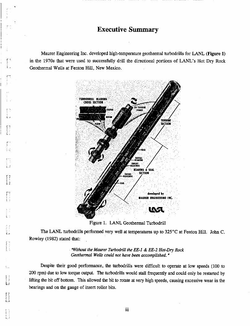
Maurer Engineering Inc. developed high-temperature geothermal turbodrills for LANL (Figure 1) in the 1970s that were used to successfully drill the directional portions of LANL's Hot Dry Rock Geothermal Wells at Fenton Hill, New Mexico.
t 'I
, . . ....
I
Figure 1. LANL Geothermal Turbodrill r s
.; The LANL turbodrills performed very well at temperatures up to 325°C at Fenton Hill. John C. Rowley (1982) stated that:
F
Without the Maurer Turbodrill the EE-I di EE-2 Hot-Dry Rock Geothermal Wells could not have been accomplished. "
Despite their good performance, the turbodrills were difficult to operate at low speeds (100 to 200 rpm) due to low torque output. The turbodrills would stall frequently and could only be restarted by lifting the bit off bottom. This allowed the bit to rotate at very high speeds, causing excessive wear in the bearings and on the gauge of insert roller bits.
, - t j
i I J
iii . . 1 ! j j / I :i
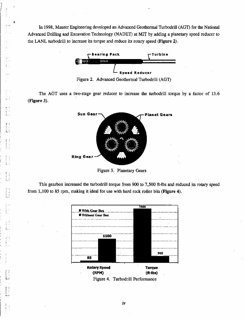
In 1998, Maurer Engineering developed an Advanced Geothermal Turbodrill (AGT) for the National Advanced Drilling and Excavation Technology (NADET) at MIT by adding a planetary speed reducer to the LANL turbodrill to increase its torque and reduce its rotary speed (Figure 2).
y B e a r i n g Pack y T u r b i n e
Speed Reducer
Figure 2. Advanced Geothermal Turbodrill (AGT)
The AGT uses a two-stage gear reducer to increase the turbodrill torque by a factor of 13.6 (Figure 3).
Figure 3. Planetary Gears
This gearbox increased the turbodrill torque from 900 to 7,500 ft-lbs and reduced its rotary speed from 1,100 to 85 rpm, making it ideal for use with hard rock roller bits (Figure 4).
I U""
........... ..WltL.Ge.W..R!~ ............................................. ................................ Without Gear Box
................................
.............................................................................................. ....................... ". .....
..............................................
........................................ .......................... ................................
.......................... .................................
Rotary Speed Torque W M ) (ft-lbs) Figure 4. Turbodrill Performance
iv
.. ̂ ...
......
.......
....... 1.- .......
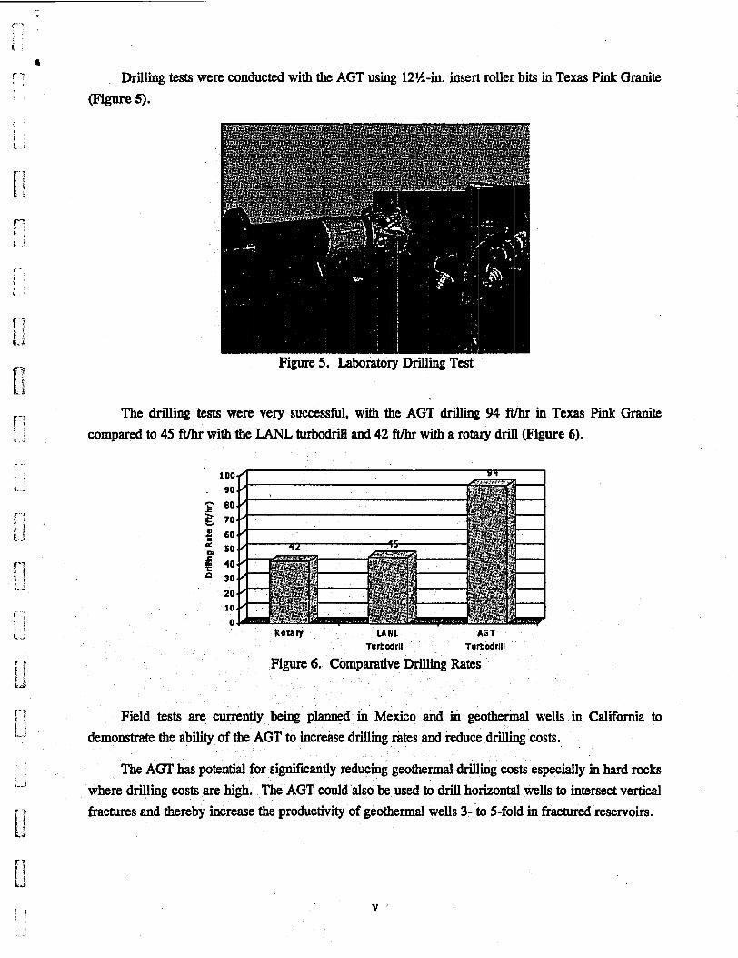
Drilling tests were conducted with the AGT using 12%-in. insert roller bits in Texas Pink Granite (Figure 5).
The compared
Figure 5. Laboratory Drilling Test
drilling tests were very successful, with the AGT drilling 94 ftmt. in Texas to 45 ft/hr with the LANL turbadrill and 42 ft/hr with a rotary drill (Figure 6).
E 80
e 50
e 70
# 60
i 40 30
drilling tests were very successful, with the AGT drilling 94 ftmt. in Texas to 45 ft/hr with the LANL turbadrill and 42 ft/hr with a rotary drill (Figure 6).
100 . 90
e 70
# 60
i 40 30 20 10
0
E 80
e 50
Pink Granite
Rota q U N L AGT Tu rbod rill furbodrlll
Figure 6. Comparative Drilling Rates
Field tests are currently behg planned in Mexico and in geothermal wells in California to demonstrate the ability of the AGT to increase drilling rates and reduce drilling costs.
The AGT has potential for significantly reducing geothermal drilling costs especially in hard rocks where drilling costs are high. The AGT could also be used to drill horizontal wells to intersect vertical fractures and thereby increase the productivity of geothermal wells 3--to 5-fold in fractured reservoirs.
V '
1. Conclusions and Recommendations
The following conclusions were reached as a result of the NADET and DOE Phase I studies:
NADET CONCLUSIONS AND RECOMMENDATIONS:
1.
2.
3.
4.
5.
6.
The Advanced Geothermal Turbodrill (AGT) represents a major breakthrough in geothermal drilling technology.
The AGT drilled Texas Pink granite at 94 ft/hr, a record drilling rate in this hard rock.
The high drilling rates should significantly reduce drilling costs in deep, hot geothermal wells.
The AGT operates at the high torques and low speeds required with insert roller bits used to drill hard, geothermal rocks.
The AGT can be equipped with bent housings to directionally drill horizontal geothermal wells that will intersect multiple fractures and increase production rates 3- to 5-fold.
The AGT should be field tested and commercialized as soon as possible since it has potential to significantly improve the economics of geothermal energy recovery.
DOE PHASE I CONCLUSIONS AND RECOMMENDATIONS:
1.
2.
3.
4.
5.
6.
7 .
Modifying the entrance angles on the turbine blades increased the overall efficiency of the AGT from 30 to 43 percent.
Dynamometer tests showed that the efficiency of the Vector Oil Tool two-stage gearbox (13.4:l) ranges from 75 to 85 percent.
MEI has modified its proprietary turbine design program TURBO to include gearbox speed ratio and efficiency. Dynamometer tests confirmed that the modified TURBO program accurately predicts AGT performance under normal operating conditions.
Pemex has agreed to provide an oilwell near Reynosa, Mexico, for field testing the AGT, provided the tests can be conducted in May or June, 1999.
ME1 developed a well test plan for the Reynosa well using offset well data provided by Pemex.
The Reynosa, Mexico test will be conducted as soon as the DOE releases funding for Phase II field tests.
1-1
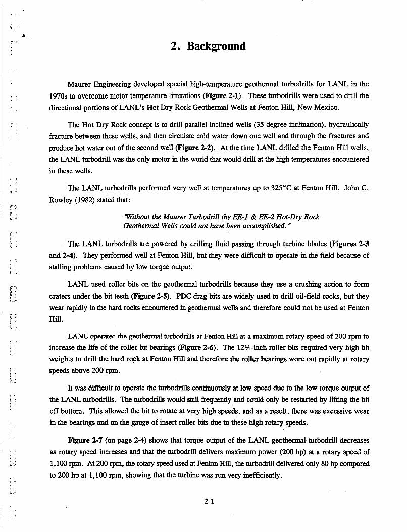
2. Background
Maurer Engineering developed special high-temperature geothermal turbodrills for LANL in the 1970s to overcome motor temperature limitations (Figure 2-1). These turbodrills were used to drill the directional portions of LANL's Hot Dry Rock Geothermal Wells at Fenton Hill, New Mexico.
The Hot Dry Rock concept is to drill parallel inclined wells (35degree inclination), hydraulically fracture between these wells, and then circulate cold water down one well and through the fractures and produce hot water out of the second well (Figure 2-2). At the time LANL drilled the Fenton Hill wells, the LANL turbodrill was the only motor in the world that would drill at the high temperatures encountered in these wells.
The LANL turbodrills performed very well at temperatures up to 325°C at Fenton Hill. John C. Rowley (1982) stated that:
Without the Maurer Turbodrill the EE-I & EE-2 Hot-Dry Rock Geothermul Wells could not have been accomplished. a
The LANL turbodrills are powered by drilling fluid passing through turbine blades (Figures 2-3 and 2-4). They performed well at Fenton Hill, but they were difficult to operate in the field because of stalling problems caused by low torque output.
LANL used roller bits on the geothermal turbodrills because they use a crushing action to form craters under the bit teeth ( F i e 2-5). PDC drag bits are widely used to drill oil-field rocks, but they wear rapidly in the hard rocks encountered in geothermal wells and therefore could not be used at Fenton Hill.
LANL operated the geothermal turbodrills at Fenton Hill at a maximum rotary speed of 200 rpm to
increase the life of the roller bit bearings (Figure 2-6). The 12%-inch roller bits required very high bit weights to drill the hard rock at Fenton Hill and therefore the roller bearings wore out rapidly at rotary speeds above 200 rpm.
It was difficult to operate the turbodrills continuously at low speed due to the low torque output of the LANL turbodrills. The turboddls would stall frequently and could only be restarted by lifting the bit off bottom. This allowed the bit to rotate at very high speeds, and as a result, there was excessive wear in the bearings and on the gauge of insert roller bits due to these high rotary speeds.
Figure 2-7 (on page 2-4) shows that torque output of the LANL geothermal turbodrill decreases as rotary speed increases and that the turbodrill delivers maximum power (200 hp) at a rotary speed of 1,100 rpm. At 200 rpm, the rotary speed used at Fenton Hill, the turbodrill delivered only 80 hp compared to 200 hp at 1,100 rpm, showing that the turbine was run very inefficiently.
2-1
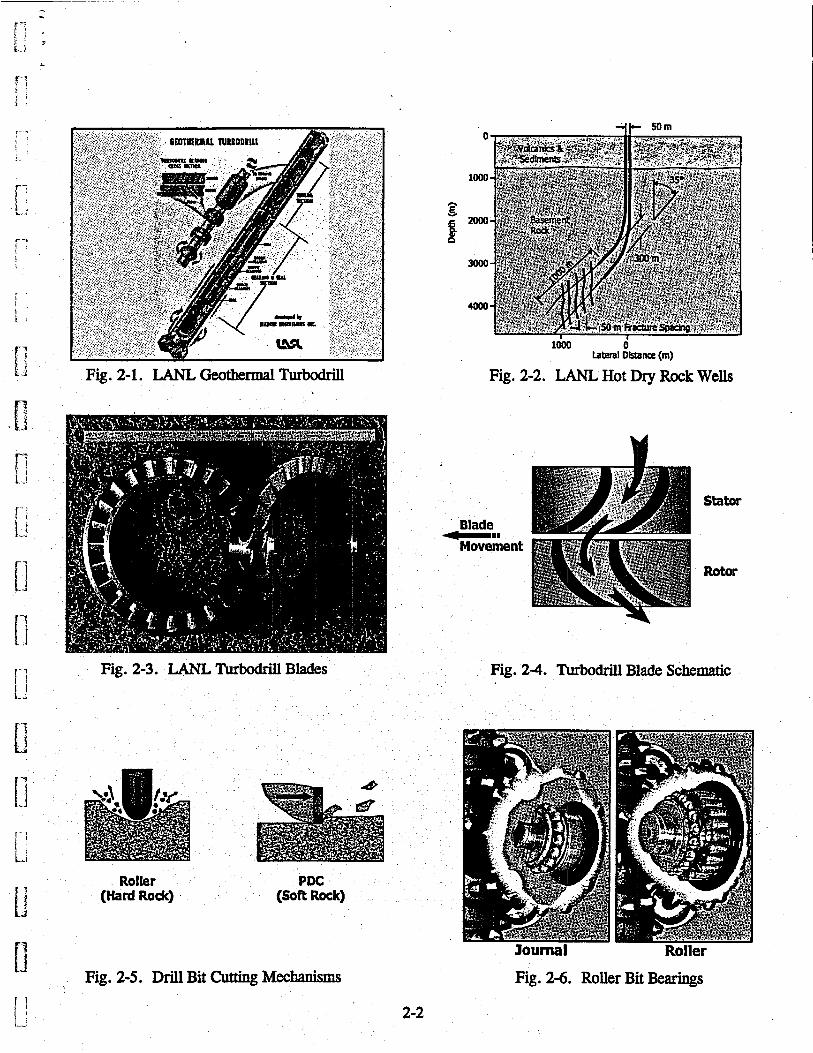
Fig. 2-1. LANL Geothermal Turbodrill
w
0
d
0
1000
1 3000
d Laterel Dhtanae (m)
Fig. 2-2. LANL Hot Dry Rock Wells
Blade Movement
Stator
Rotor
Fig. 2-3. LANL Turbodrill Blades Fig. 24. Turbodrill Blade Schematic
Roller (Hard Roe) .
PDC (Soft Rock)
Journal Roller Fig. 2-5. Drill Bit Cutting Mechanisms Fig. 2-6. Roller Bit Bearings
2-2
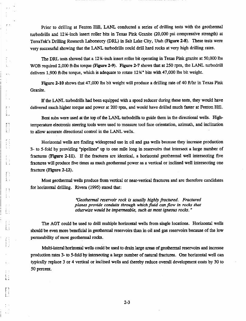
Prior to drilling at Fenton Hill, LANL conducted a series of drilling tests with the geothermal turbodrills and 12%-inch insert roller bits in Texas Pink Granite (20,000 psi compressive strength) at TerraTek's Drilling Research Laboratory (DRL) in Salt Lake City, Utah (Figure 2-8). These tests were very successful showing that the LANL turbodrills could drill hard rocks at very high drilling rates.
The DRL tests showed that a 12%-inch insert roller bit operating in Texas Pink granite at 50,000 lbs WOB required 2,000 ft-lbs torque (Figure 2-9). Figure 2-7 shows that at 250 rpm, the LANL turbodrill delivers 1,900 ft-lbs torque, which is adequate to rotate 12%" bits with 47,000 lbs bit weight.
Figure 2-10 shows that 47,000 lbs bit weight will produce a drilling rate of 40 ft/hr in Texas Pink Granite.
If the LANL turbodrills had been equipped with a speed reducer during these tests, they would have delivered much higher torque and power at 200 rpm, and would have dr ied much faster at Fenton Hill.
Bent subs were used at the top of the LANL turbodrills to guide them in the directional wells. High- temperature electronic steering tools were used to measure tool face orientation, azimuth, and inclination to allow accurate directional control in the LANL wells.
Horizontal wells are finding widespread use in oil and gas wells because they increase production 3- to 5-fold by providing "pipelines" up to one mile long in reservoirs that intersect a large number of fractures (Figure 2-11). If the fractures are identical, a horizontal geothermal well intersecting five fractures will produce five times as much geothermal power as a vertical or inclined well intersecting one fracture (Figure 2-12).
Most geothexmal wells produce from vertical or near-vertical fractures and are therefore candidates for horizontal drilling. Rivera (1995) stated that:
"Geotheml reservoir rock is usually highly fiactured. Fractured planes provide conduits through which fluid can flow in rocks that otherwise would be impermeable, such as most igneous rocks.
The AGT could be used to drill multiple horizontal wells from single locations. Horizontal wells should be even more beneficial in geothermal reservoirs than in oil and gas reservoirs because of the low permeability of most geothermal rocks.
Multi-lateral horizontal wells could be used to drain large areas of geothermal reservoirs and increase production rates 3- to 5-fold by intersecting a large number of natural fractures. One horizontal well can
typically replace 3 or 4 vertical or inclined wells and thereby reduce overall development costs by 30 to 50 percent.
2-3
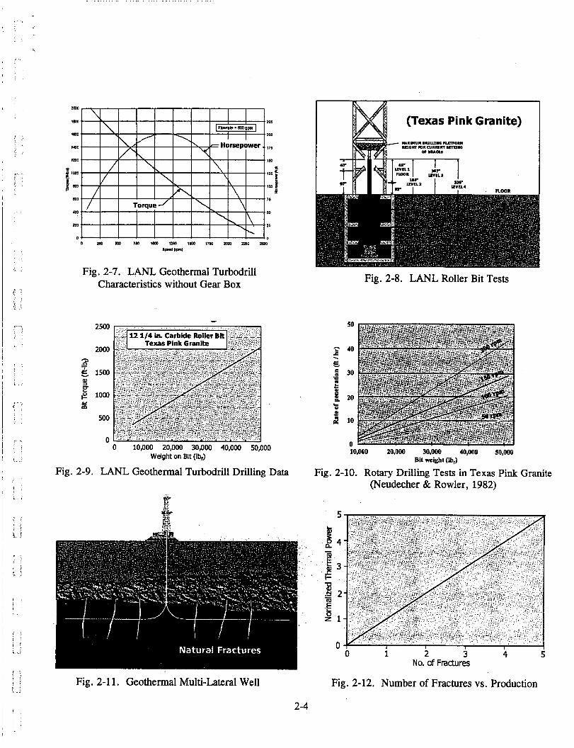
Fig. 2-7. LANL Geothermal Turbodrill Characteristics without Gear Box
- 2500
Texas Pink Granite I 1
0 10,000 20,000 30,000 40,000 50,000 Weight on Blt (lb,)
Fig. 2-9. LANL Geothermal Turbodrill Drilling Data
Fig. 2-1 1. Geothermal Multi-Lateral Well
(Texas Pink Granite)
Fig. 2-8. LANL Roller Bit Tests
50
8 40
E P .
30 z 1 20 e CI
B 10
n 10,000 20,000 30,000 40,000 50,000
Bit weight (Ib,)
Fig. 2-10. Rotary Drilling Tests in Texas Pink Granite (Neudecher & Rowler, 1982)
0 i 2 3 4 s No. of Fractures
Fig. 2-12. Number of Fractures vs. Production
2-4
3. NADET Geared Turbodrill Development
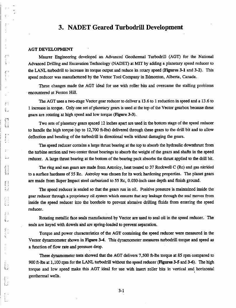
AGT DEVELOPMENT Maurer Engineering developed an Advanced Geothermal Turbodrill (AGT) for the National
Advanced Drilling and Excavation Technology (NADET) at MIT by adding a planetary speed reducer to the LANL turbodrill to increase its torque output and reduce its rotary speed (Figures 3-1 and 3-2). This speed reducer was manufactured by the Vector Tool Company in Edmonton, Alberta, Canada.
These changes made the AGT ideal for use with roller bits and overcame the stalling problems encountered at Fenton Hill.
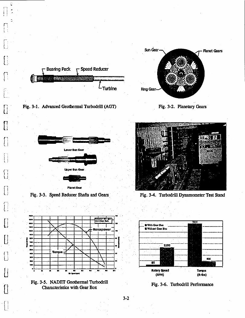
The AGT uses a two-stage Vector gear reducer to deliver a 13.6 to 1 reduction in speed and a 13.6 to 1 increase in torque. Only one set of planetary gears is used at the top of the Vector gearbox because these gears are rotating at high speed and low torque (Figure 3-3).
Two sets of planetary gears spaced 12 inches apart are used in the bottom stage of the speed reducer to handle the high torque (up to 12,700 ft-lbs) delivered through these gears to the drill bit and to allow deflection and bending of the turbodrill in directional wells without damaging the gears.
The speed reducer contains a large thrust bearing at the top to absorb the hydraulic downthrust from the turbine section and two center thrust bearings to absorb the weight of the gears and shafts in the speed reducer. A large thrust bearing at the bottom of the bearing pack absorbs the thrust applied to the drill bit.
The ring and sun gears are made from Astroloy, heat treated to 37 Rockwell C (Rc) and gas nitrided to a surface hardness of 55 Rc. Astroloy was chosen for its work hardening properties. The planet gears are made from Super Impact steel carburized to 55 Rc, 0.030-inch case depth and finish ground.
The speed reducer is sealed so that the gears run in oil. Positive pressure is maintained inside the gear reducer through a proprietary oil system which ensures that any leakage through the seal moves from inside the speed reducer into the borehole to prevent abrasive drilling fluids from entering the speed reducer.
Rotating metallic face seals manufactured by Vector are used to seal oil in the speed reducer. The seals are keyed with dowels and are spring-loaded to prevent separation.
Torque and power characteristics of the AGT containing the speed reducer were measured in the Vector dynamometer shown in Figure 3-4. This dynamometer measures turbodrill torque and speed as a function of flow rate and pressure drop.
These dynamometer tests showed that the AGT delivers 7,500 ft-lbs torque at 85 rpm compared to 900 ft-lbs at 1,100 rpm for the LANL turbodrill without the speed reducer (Figures 3-5 and 3-6). The high torque and low speed make this AGT ideal for use with insert roller bits in vertical and horizontal geothermal wells.
#
3- 1
i
f - ; Fig. 3-1. Advanced Geothermal Turbodrill (AGT) b.i
Lower Sun Gear
Upper Sun Oear
Fig. 3-2. Planetary Gears
Fig. 3 3 . Speed Reducer Shafts and Gears Fig. 3-4. Turbodrill Dynamometer Test Stand
Fig. 3-6. Turbodrill Performance Fig. 3-5. NADET Geothermal Turbodrill Characteristics with Gear Box
3-2
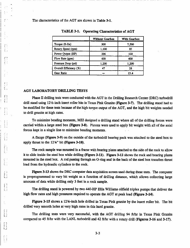
The characteristics of the AGT are shown in Table 3-1.
TABLE 3-1. Operating Characteristics of AGT
I Without Gearbox I With Gearbox
Torque (ft-lbs)
Rotary Speed (rpm) Power Output (HP)
Flow Rate (gpm) 600 600
I Pressure Drop (psi) I 1,200 1 2 0 0 - 7 I Overall Efficiency (76) I 47 - 1 2 8 1
I I 13.4 Gear Ratio - I
AGT LABORATORY DRILLING TESTS
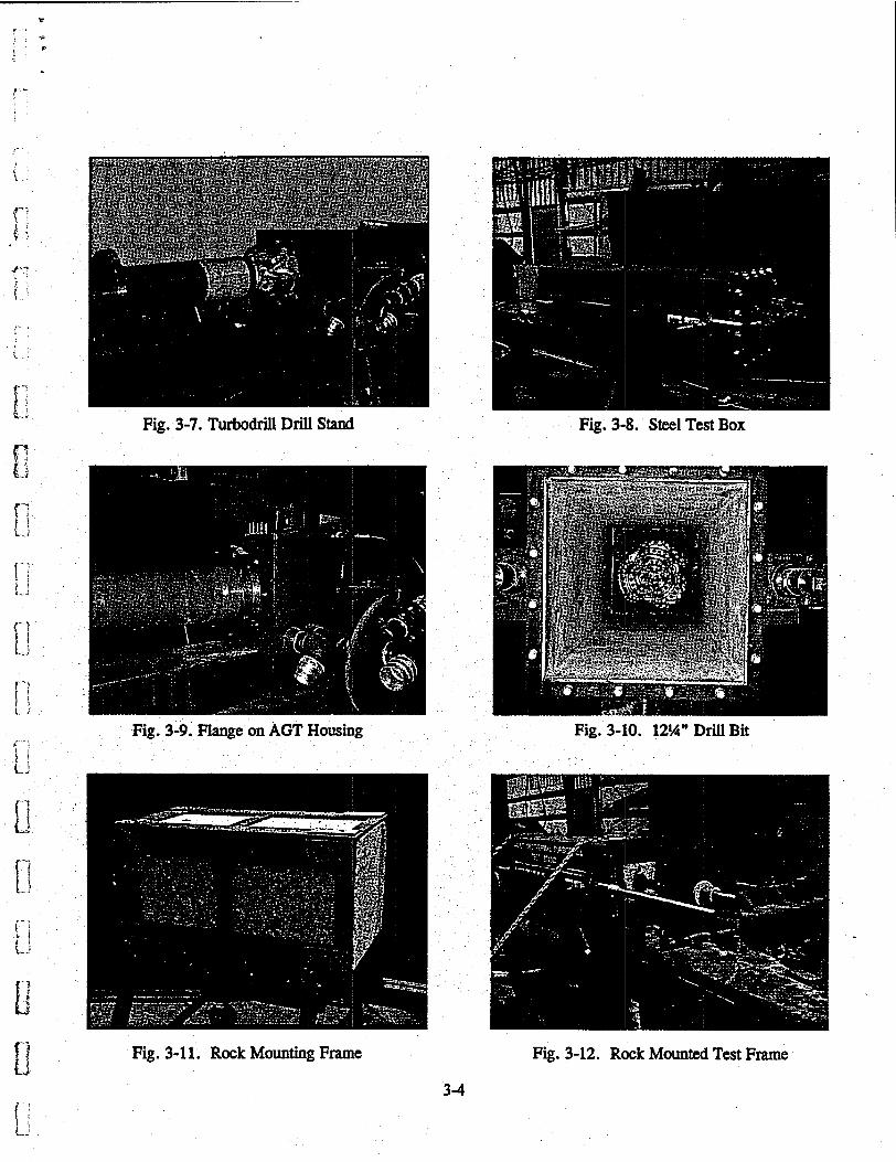
Phase II drilling tests were conducted with the AGT in the Drilling Research Center (DRC) turbodrill drill stand using 12%-inch insert roller bits in Texas Pink Granite (Figure 3-7). The drilling stand had to be modified for these tests because of the high torque output of the AGT, and the high bit weights needed to driil granite at high rates.
To minimize bending moments, ME1 designed a drilling stand where all of the drilling forces were carried within a large steel box (Figure 3-8). Pistons were used to apply bit weight with all of the axial forces kept in a single line to minimize bending moments.
A flange (Figure 3-9) on the outside of the turbodrill bearing pack was attached to the steel box to apply thrust to the 12 !4 bit (Figure 3-10).
The rock sample was mounted in a frame with bearing plates attached to the side of the rock to allow it to slide inside the steel box while drilling @gure 3-11). Figure 3-12 shows the rock and bearing plates mounted in the steel box. A rod passing through an O-ring seal in the back of the steel box transfers thrust load from the hydraulic cylinders to the rock.
Figure 3-13 shows the DRC computer data acquisition screen used during these tests. The computer is preprogrammed to vary bit weight as a function of drilling distance, which allows collecting large amounts of data while drilling only 3 feet in a rock sample.
The drilling stand is powered by two 440-HP Ellis Williams oilfield triplex pumps that deliver the high flow rates and high pressures required to operate the AGT at peak load (Figure 3-14).
Figure 3-15 shows a 12%-inch hole drilled in Texas Pink granite by the insert roller bit. The bit drilled very smooth holes at very high rates in this hard granite.
The drilling tests were very successful, with the AGT drilling 94 ft/hr in Texas Pink Granite compared to 45 ft/hr with the LANL turbodrill and 42 ft/hr with a rotary drill (Figures 3-16 and 3-17).
3-3
c-
F' -; E ' a i
Fig. 3-7. Turbodrill Drill Stand Fig. 3-8. Steel Test Box
Fig. 3-9. Flange on AGT Housing Fig. 3-10. 12%" Drill Bit
Fig. 3-1 1. Rock Mounting Frame Fig. 3-12. Rock Mounted Test Frame
3-4
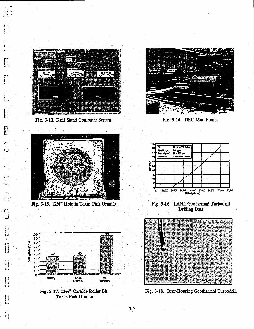
Fig. 3-13. Drill Stand Computer Screen ,
Fig. 3-14. DRC Mud W p s
Fig, 3-15. 12%" Hole in Texas Pink Granite Fig. 3-16. LANL Geothermal Turbodrill Drilling Data
Fig. 3-17. 12%" Carbide Roller Bit Texas Pink Granite
Fig. 3-18. Bent-Housing Geothermal Turbodrill
3-5
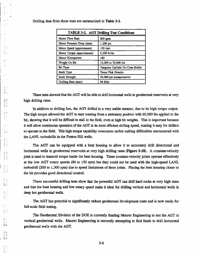
Drilling data from these tests are summarized in Table 3-2.
Motor Pressure Drop (max) Motor Speed (approximate) Motor Torque (approximate)
TABLE 3-2. AGT Drilling Test Conditions
Motor Flow Rate I 6 O o ~ r n 1.200 psi 100 rpm 9.500 ft-lbs
Motor Horsepower Weight On Bit Bit Type
1 80 10,OOO to 70,000 lbs Tungsten Carbide Tri-Cone Roller
Rock Type Rock Strength Drilling Rate (max)
These tests showed that the AGT will be able to drill horizontal wells in geothermal reservoirs at very high drilling rates.
Texas Pink Granite 20,000 psi (compressive) 94 ft/hr
In addition to drilling fast, the AGT drilled in a very stable manner, due to its high torque output. The high torque allowed the AGT to start rotating from a stationary position with 60,000 lbs applied to the bit, showing that it will be difficult to stall in the field, even at high bit weights. This is important because it will allow continuous operation of the AGT at its most efficient drilling speed, making it easy for drillers to operate in the field. This high torque capability overcomes earlier stalling difficulties encountered with the LANL turbodrills in the Fenton Hill wells.
The AGT can be equipped with a bent housing to allow it to accurately drill directional and horizontal wells in geothermal reservoirs at very high drilling rates (Figure 3-18). A constant-velocity joint is used to transmit torque inside the bent housing. These constant-velocity joints operate effectively at the low AGT rotary speeds (80 to 150 rpm) but they could not be used with the high-speed LANL turbodrill (200 to 1,300 rpm) due to speed limitations of these joints. Placing the bent housing closer to the bit provides good directional control.
These successful drilliig tests show that the powerful AGT can drill hard rocks at very high rates and that the bent housing and low rotary speed make it ideal for drilliig vertical and horizontal wells in deep hot geothermal wells.
The AGT has potential to significantly reduce geothermal development costs and is now ready for full-scale field testing.
The Geothermal Division of the DOE is currently funding Maurer Engineering to test the AGT in vertical geothermal wells. MaGer Engineering is currently attempting to find funds to drii horizontal geothermal wells with the AGT.
3-6
4.
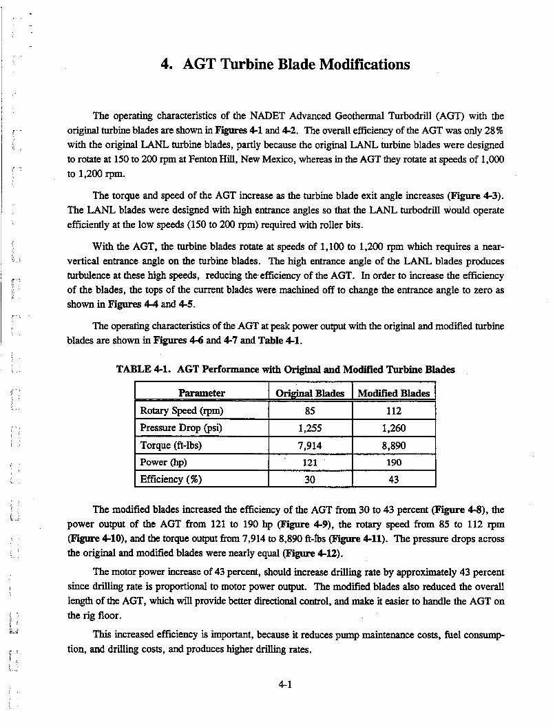
Parameter
Rotary speed (rpm) Pressure Drop (psi)
Torque (it-lbs) Power (hp)
Efficiency (%)
AGT Turbine Blade Modifications
Original Blades Modified Blades
85 112
1,255 1,260
7,914 8,890
121 190
30 43
The operating characteristics of the NADET Advanced Geothermal Turbodrill (AGT) with the original turbine blades are shown in Figures 4-1 and 4-2. The overall efficiency of the AGT was only 28 ?6 with the original LANL turbine blades, partly because the original LANL turbine blades were designed to rotate at 150 to 200 rpm at Fenton Hill, New Mexico, whereas in the AGT they rotate at speeds of 1,OOO to 1,200 rpm.
The torque and speed of the AGT increase as the turbine blade exit angle increases ( F i e 4-3). The LANL blades were designed with high entrance angles so that the LANL turbodrill would operate efficiently at the low speeds (150 to 200 rpm) required with roller bits.
With the AGT, the turbine blades rotate at speeds of 1,100 to 1,200 rpm which requires a near- vertical entrance angle on the turbine blades. The high entrance angle of the LANL blades produces turbulence at these high speeds, reducing theefficiency of the AGT. In order to increase the efficiency of the blades, the tops of the current blades were machined off to change the entrance angle to zero as shown in Figures 4-4 and 4-5.
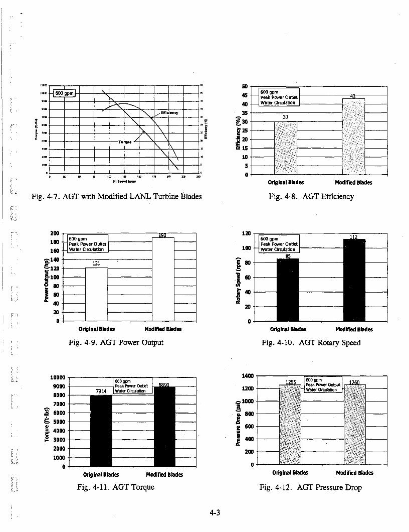
The operating characteristics of the AGT at peak power output with the original and modified turbine blades are shown in Figures 4-6 and 4-7 and Table 4-1.
The modified blades increased the efficiency of the AGT from 30 to 43 percent (Figure 4-8), the power output of the AGT from 121 to 190 hp (Figure 4-9), the rotary speed from 85 to 112 rpm (Figure 4-10), and the torque output from 7,914 to 8,890 fi-lbs (Figure 4-11). The pressure drops across the original and modified blades were nearly equal (Figure 4-12).
The motor power increase of 43 percent, should increase drilling rate by approximately 43 percent since drilling rate is proportional to motor power output. The modified blades also reduced the overall length of the AGT, which will provide better directional control, and make it easier to handle the AGT on the rig floor.
This increased efficiency is important, because it reduces pump maintenance costs, fuel consump- tion, and drilling costs, and produces higher drilling rates.
4-1
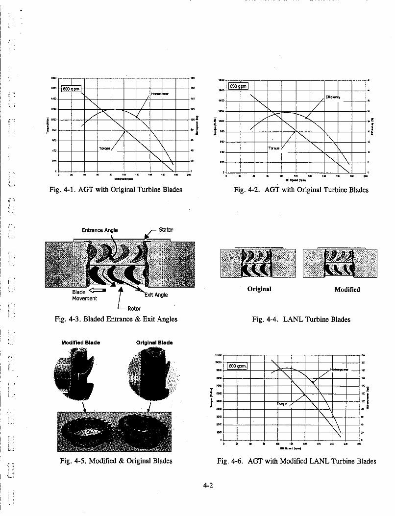
Fig. 4-1. AGT with Original Turbine Blades Fig. 4-2. AGT with Original Turbine Blades
Entrance Angle ,- Stator
vi+ A n n l e - 7 Movement
L Rotor
Fig. 4-3. Bladed Entrance & Exit Angles
Modified Blade Original Blade
Fig. 4-5. Modified & Original Blades
Original Modified
Fig. 4-4. LANL Turbine Blades
Fig. 4-6. AGT with Modified LANL Turbine Blades
4-2
I I I I I I I I I o zs ID n im izs im in zm za zm
811 8p.d lrpn)
Fig. 4-7. AGT with Modified LANL Turbine Blades
mm 0 Original Blades Modlfied Blades
Fig. 4-9. AGT Power Output I .
10000 1 I I
9000 80 00 70 00 6000
& 5000 4000
8 3000 2000 10 00
0
0
Original Blades Modified Blades
Fig. 4-1 1 . AGT Torque
50 45 40 35
g30 U 1: 15 10 5 0
Original Blades Modified Blades
Fig. 4-8. AGT Efficiency
1400
l200
0
Original Blades Modified Blades
Fig. 4-10. AGT Rotary Speed
Original Blades Modified Blades
Fig. 4-12. AGT Pressure Drop
4-3
5. AGT Gearbox Efficiency
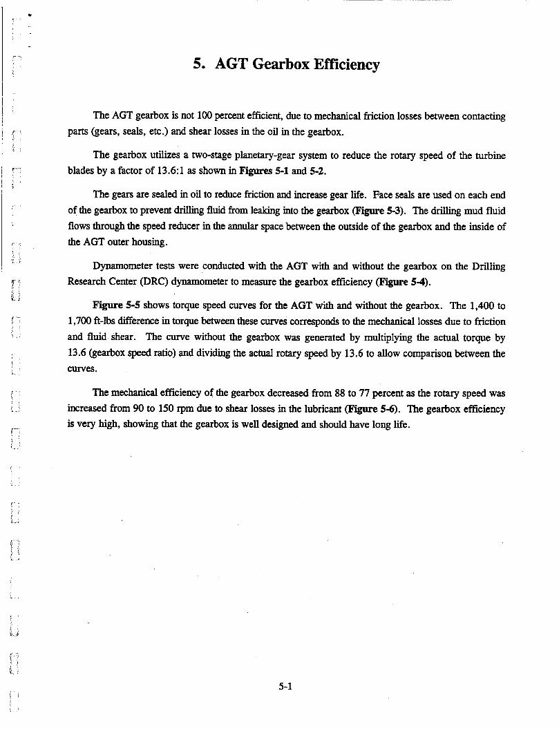
The AGT gearbox is not 100 percent efficient, due to mechanical friction losses between contacting parts (gears, seals, etc.) and shear losses in the oil in the gearbox.
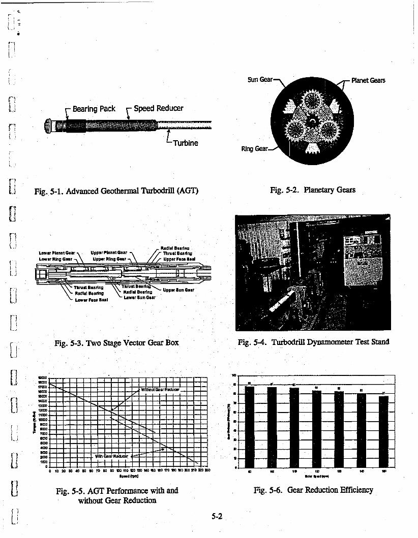
The gearbox utilizes a two-stage planetary-gear system to reduce the rotary speed of the turbine blades by a factor of 13.6: 1 as shown in figures 5-1 and 5-2.
The gears are sealed in oil to reduce friction and increase gear life. Face seals are used on each end of the gearbox to prevent drilling fluid from leaking into the gearbox (Figure 5-3). The drilling mud fluid flows through the speed reducer in the annular space between the outside of the gearbox and the inside of the AGT outer housing.
Dynamometer tests were conducted with the AGT with and without the gearbox on the Drilling Research Center (DRC) dynamometer to measure the gearbox efficiency (Figure 5-4).
Figure 5-5 shows torque speed curves for the AGT with and without the gearbox. The 1,400 to 1,700 fi-lbs difference in torque between these curves corresponds to the mechanical losses due to friction and fluid shear. The curve without the gearbox was generated by multiplying the actual torque by 13.6 (gearbox speed ratio) and dividing the actual rotary speed by 13.6 to allow comparison between the curves.
The mechanical efficiency of the gearbox decreased from 88 to 77 percent as the rotary speed was increased from 90 to 150 rpm due to shear losses in the lubricant (Figure 5-6). The gearbox efficiency is very high, showing that the gearbox is well designed and should have long life.
...
5-1
r Bearing Pack Speed Reducer
LTurbine
Fig. 5-1. Advanced Geothermal Turbodrill (AGT) Fig. 5-2. Planetary Gears
Lowar Planat Gear , Upper Pbnat mar 7 L--=SE:%n
Fig. 5-3. Two Stage Vector Gear Box Fig. 54. Turbodrill Dynamometer Test Stand
W ' I
Fig. 5-5. AGT Performance with and without Gear Reduction
Fig. 5-6. Gear Reduction Efficiency
5-2
6. TURBO Turbodrill Design Calculations
PiWUlletW
Power Output (hp)
Overall Efficiencv ( %) < - . .
A I I . .
Predicted Actual
189 188
43 43
f : L ".
Torque (ft-lbs)
Rotary Speed (rpm) Pressure Drop (psi)
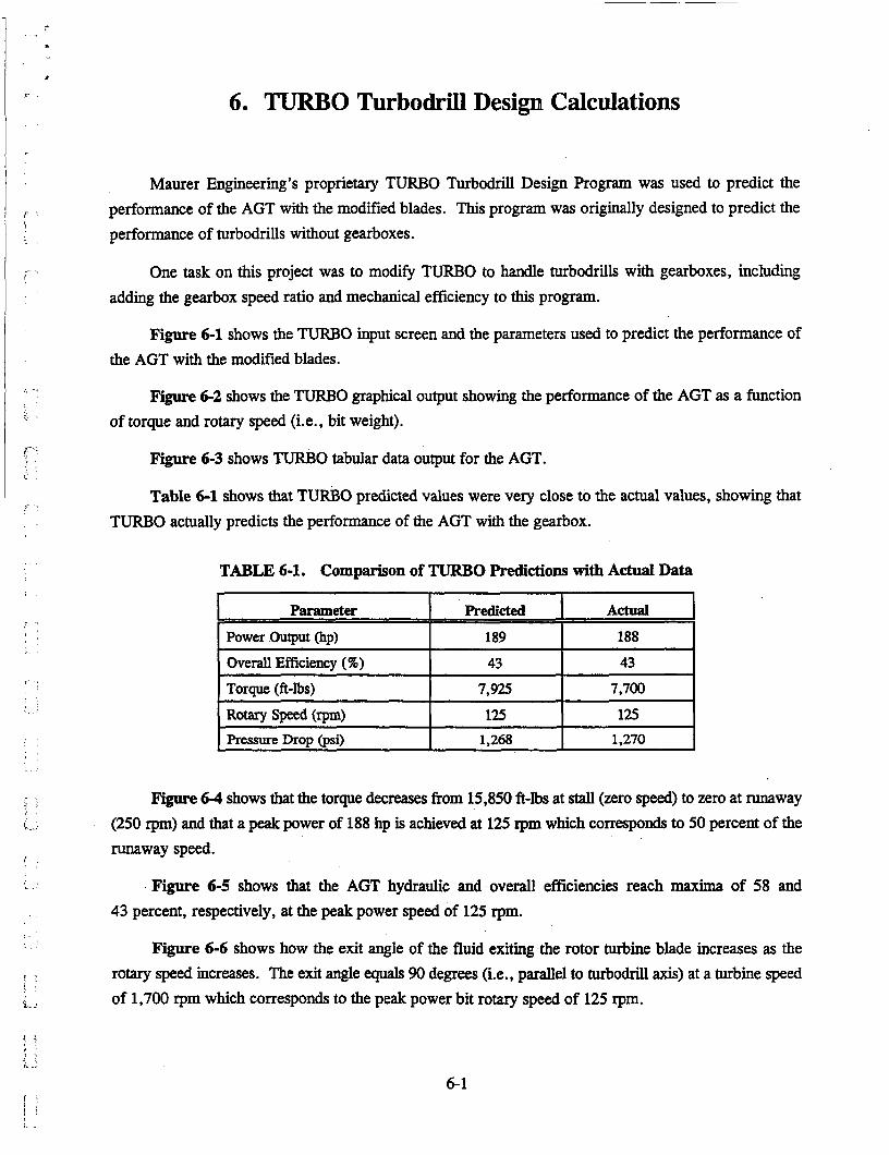
Maurer Engineering's proprietary TURBO Turbodrill Design Program was used to predict the performance of the AGT with the modified blades. This program was originally designed to predict the performance of turbodrills without gearboxes.
7,925 7,700 125 125 1,268 1,270
One task on this project was to modify TURBO to handle turbodrills with gearboxes, including adding the gearbox speed ratio and mechanical efficiency to this program.
Figure 6-1 shows the TURBO input screen and the parameters used to predict the performance of the AGT with the modified blades.
Figure 6-2 shows the TURBO graphical output showing the performance of the AGT as a function of torque and rotary speed (i.e., bit weight).
Figure 6-3 shows TURBO tabular data output for the AGT.
Table 6-1 shows that TURBO predicted values were very close to the actual values, showing that TURBO actually predicts the performance of the AGT with the gearbox.
TABLE 6-1. Comparison of TURBO Predictions with Actual Data
F'igure 6-4 shows that the torque decreases from 15,850 ft-lbs at stall (zero speed) to zero at runaway (250 rpm) and that a peak power of 188 hp is achieved at 125 rpm which corresponds to 50 percent of the runaway speed.
Figure 6 5 shows that the AGT hydraulic and overall efficiencies reach maxima of 58 and 43 percent, respectively, at the peak power speed of 125 rpm.
Figure 6-6 shows how the exit angle of the fluid exiting the rotor turbine blade increases as the rotary speed increases. The exit angle equals 90 degrees (i.e., parallel to turbodrill axis) at a turbine speed of 1,700 rpm which corresponds to the peak power bit rotary speed of 125 rpm.
6-1
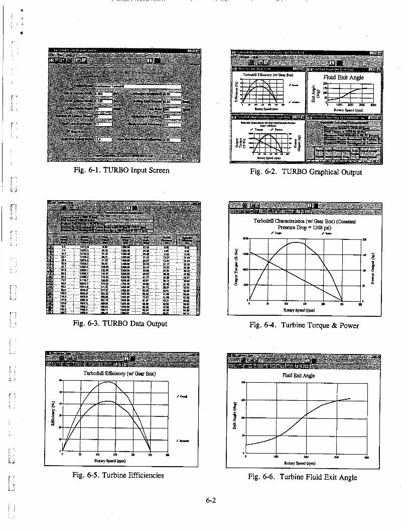
Fig. 6-1. TURBO Input Screen Fig. 6-2. TURBO Graphical Output
Turbodrin Chtmckr&ics (w/ Gear Box) (Constant pressureDrop=1268psi)
1 7-F /h.n
Fig. 6-3. TURBO Data Output Fig. 6-4. Turbine Torque & Power
I Turbomill Efficiency (w/ Gear Box) I
2 .- F 4
I I I \\ I
Fig. 6-5. Turbine Efficiencies
6-2
Fig. 6-6. Turbine Fluid Exit Angle
!- '
k. .i
b. ..
7. References
Cohen, John H., and Maurer, William C., 1999: "Laboratory Drilling Tests of Advanced Geothermal/Turbodrill, " ETCE99-6650, presented at the Energy Sources Technology Conference & Exhibition, held in Houston, Texas, February 1-7.
Helmick, C., Koczan, S., and Pettitt, R., 1982: "Planning and Drilling Geothermal Energy Extraction Hole EE-2," LA-9302-HDR, UC-66bY April.
Maurer, William C., and Matson, Larry, 1977: "New Turbodrill for Geothermal Drilling," proceedings of the 12" Intersociety Energy Conversion Engineering Conference, Washington, DC, August 28 - September 2.
Maurer, William C., 1978: "Advanced Turbodrills for Geothermal Wells," proceedings of the 1978 Geothermal Resources Council Annual Meeting, Hilo, Hawaii, July 25-28.
Maurer, William C., 1979: "Geothermal Turbodrill Field Tests," proceedings of the 1979 Geothermal Resources Council Annual Meeting, Transactions, Vol. 3, September.
Jouml , December 1. Maurer, William C., 1980: "Hi-Temperature Turbodrill Set for Production in Japan," Oil & Gas
Maurer, William C., 1981: "Geothermal Turbodrill Ready for Oil-Fidd Use," Oil & Gas Jouml,
Maurer, William C., Cohen, John H., and Craig, Daniel, 1997: "NADET Advanced Geothermal
Maurer, William C., Cohen, John H., and Rowley, John, 1998: "Advanced Geothermal Turbodrill,"
Maurer, William C., and Cohen, John H., 1999: "NADET Advanced Geothermal Turbodrill (AGT)," TR99-6, Phase 11 Final Report, March.
Neudecker, J.W., and Rowley, J.C. , 1982: "High-Temperature Directional Drilling Turbodrill," LA-9231-MS, UC-66c, February.
Rivera, JesuS, 1995: "Reservoir Engineering Aspects Related to Injection - Chapter 1," Injection Technology, International Geothermal Association, Inc., WGC '95 Pre-Congress Course, Pisa, Italy, May 18-20.
Rowley, John C., and Carden, Richard S., 1982: "Drilling of Hot Dry Rock Geothermal Energy Extraction Well EE-3," LA-9512-HDR, UC-66c, August.
Rowley, John C., 1982: Personal Communications, Los Alamo Scientific Laboratories, Los Alamos, New Mexico.
March 9.
Turbodrill (AGT)," TR97-20, Phase I Final Report, September.
GRC Bulletin, June.
7- 1