Field Management Design Plan Appendix O-1
51
Field Management Design Plan Appendix O-1 TABLE OF CONTENTS Page No. I. INTRODUCTION .................................................................................................. 1 II. GREATER SPRINGFIELD RELIABILITY PROJECT .......................................... 3 II.1 Project Description and Base Line Design ......................................................................... 3 II.2 Focus Areas for Magnetic Field Management .................................................................... 4 II.3 Base GSRP Line Design and Alternative GSRP Line Designs for Magnetic Field Reductions in Focus Area ................................................................................................... 4 II.3.1 Horizontal Conductor Configuration Using 345-kV H-Frame Line Structures, the Base Line Design ................................................................................................... 4 II.3.2 345-kV Delta Line Configuration .......................................................................... 6 II.3.3 345-kV Vertical Line Configuration...................................................................... 7 II.3.4 345-kV Split-Phase Line Configuration ................................................................ 8 II.3.5 345/115-kV Composite Line Configuration .......................................................... 9 II.3.6 Conductor Heights Above Ground ...................................................................... 10 II.3.7 Conductor Separation .......................................................................................... 10 II.3.8 Passive Loop Shielding........................................................................................ 10 II.3.9 Shifting the ROW or Alignments of Lines on a ROW ........................................ 11 II.4 Magnetic Field Levels Produced by the Base Line Design and BMP Alternative Line Designs ............................................................................................................................. 11 II.5 CL&P Recommendation for the 3.2-mile GSRP ROW Segment ..................................... 14 II.6 Aerial maps for the Connecticut section of the North Bloomfield to Agawam 345-kV line route .................................................................................................................................. 14 II.7 Cross Sections for the Connecticut section of GSRP ....................................................... 17 III. MANCHESTER TO MEEKVILLE JUNCTION CIRCUIT SEPARATION PROJECT .......................................................................................................... 35 III.1 Project Description and Base Line Design ....................................................................... 35 III.2 Focus Areas for Magnetic Field Management .................................................................. 35 III.3 Base MMP Line Design and Alternative MMP Line Designs for Magnetic Field Reductions in Focus Areas................................................................................................ 36 III.3.1 115-kV Vertical Line Configuration Using 345-kV Class Insulation, Conductor Bundles and Phase Spacings, and Best Circuit Phasing, the Base Line Design .. 36 III.3.2 Modifications to the Existing Line ...................................................................... 37 III.3.3 Other Line Configurations ................................................................................... 37 III.3.4 Conductor Heights Above Ground ...................................................................... 37 III.3.5 Conductor Separation .......................................................................................... 38 III.3.6 Shifting the ROW or Alignments of Lines on a ROW ........................................ 38 III.3.7 Passive Loop Shielding........................................................................................ 38 III.4 Magnetic Field Levels Produced by the Base Line Design and Alternative Line Designs .......................................................................................................................................... 39 III.5 CL&P Recommendation for the 2.2-mile MMP ROW Segment ..................................... 41 III.6 Cross Sections for the MMP ............................................................................................. 42 GSRP and MMP TOC-1 October 2008
Transcript of Field Management Design Plan Appendix O-1

Field Management Design Plan Appendix O-1
TABLE OF CONTENTS
Page No.
I. INTRODUCTION .................................................................................................. 1
II. GREATER SPRINGFIELD RELIABILITY PROJECT .......................................... 3 II.1 Project Description and Base Line Design ......................................................................... 3 II.2 Focus Areas for Magnetic Field Management .................................................................... 4 II.3 Base GSRP Line Design and Alternative GSRP Line Designs for Magnetic Field
Reductions in Focus Area ................................................................................................... 4 II.3.1 Horizontal Conductor Configuration Using 345-kV H-Frame Line Structures, the
Base Line Design ................................................................................................... 4 II.3.2 345-kV Delta Line Configuration .......................................................................... 6 II.3.3 345-kV Vertical Line Configuration ...................................................................... 7 II.3.4 345-kV Split-Phase Line Configuration ................................................................ 8 II.3.5 345/115-kV Composite Line Configuration .......................................................... 9 II.3.6 Conductor Heights Above Ground ...................................................................... 10 II.3.7 Conductor Separation .......................................................................................... 10 II.3.8 Passive Loop Shielding ........................................................................................ 10 II.3.9 Shifting the ROW or Alignments of Lines on a ROW ........................................ 11
II.4 Magnetic Field Levels Produced by the Base Line Design and BMP Alternative Line Designs ............................................................................................................................. 11
II.5 CL&P Recommendation for the 3.2-mile GSRP ROW Segment ..................................... 14 II.6 Aerial maps for the Connecticut section of the North Bloomfield to Agawam 345-kV line
route .................................................................................................................................. 14 II.7 Cross Sections for the Connecticut section of GSRP ....................................................... 17
III. MANCHESTER TO MEEKVILLE JUNCTION CIRCUIT SEPARATION PROJECT .......................................................................................................... 35 III.1 Project Description and Base Line Design ....................................................................... 35 III.2 Focus Areas for Magnetic Field Management .................................................................. 35 III.3 Base MMP Line Design and Alternative MMP Line Designs for Magnetic Field
Reductions in Focus Areas................................................................................................ 36 III.3.1 115-kV Vertical Line Configuration Using 345-kV Class Insulation, Conductor
Bundles and Phase Spacings, and Best Circuit Phasing, the Base Line Design .. 36 III.3.2 Modifications to the Existing Line ...................................................................... 37 III.3.3 Other Line Configurations ................................................................................... 37 III.3.4 Conductor Heights Above Ground ...................................................................... 37 III.3.5 Conductor Separation .......................................................................................... 38 III.3.6 Shifting the ROW or Alignments of Lines on a ROW ........................................ 38 III.3.7 Passive Loop Shielding ........................................................................................ 38
III.4 Magnetic Field Levels Produced by the Base Line Design and Alternative Line Designs .......................................................................................................................................... 39
III.5 CL&P Recommendation for the 2.2-mile MMP ROW Segment ..................................... 41 III.6 Cross Sections for the MMP ............................................................................................. 42
GSRP and MMP TOC-1 October 2008

Field Management Design Plan Appendix O-1
LIST OF FIGURES
Figure No. Page No. Figure 1: Tangent H-Frame Structure ................................................................................................ 5 Figure 2: Tangent Delta Structure ...................................................................................................... 6 Figure 3: Tangent Vertical Structure .................................................................................................. 7 Figure 4: Tangent Split-Phase Structure ............................................................................................. 8 Figure 5: Tangent Composite Structure ............................................................................................. 9 Figure 6: Magnetic Field Profiles for a 3.2-mile Section of the GSRP ROW .................................. 13 Figure 7: Aerial Map for Connecticut Portion of North Bloomfield to Agawam 345-kV Line Route,
Page 1 of 3 ........................................................................................................................ 15 Figure 8: Aerial Map for Connecticut Section of North Bloomfield to Agawam 345-kV Line Route,
Page 2 of 3 ........................................................................................................................ 16 Figure 9: Aerial Map for Connecticut Section of North Bloomfield to Agawam 345-kV Line Route,
Page 3 of 3 ........................................................................................................................ 17 Figure 10: XS-2 Cross Section, Base Configuration .......................................................................... 19 Figure 11: XS-2 Cross Section, Alternate 1 Configuration ................................................................ 21 Figure 12: XS-2 Cross Section, Alternate 2 Configuration ................................................................ 23 Figure 13: XS-2 Cross Section, Alternate 3 Configuration ................................................................ 25 Figure 14: XS-2 Cross Section, Alternate 4 Configuration ................................................................ 27 Figure 15: XS-2 Cross Section, Alternate 5 Configuration ................................................................ 29 Figure 16: XS-2 Cross Section, Alternate 6 Configuration ................................................................ 31 Figure 17: XS-2 Cross Section, Alternate 7 Configuration ................................................................ 33 Figure 18: Tangent Vertical Structure ................................................................................................ 36 Figure 19: Magnetic Field Profiles for Potential Reduction Section on MMP .................................. 41 Figure 20: XS-21 Cross Section, Base Configuration ........................................................................ 43 Figure 21: XS-21 Cross Section, Alternate 1 Configuration .............................................................. 45 Figure 22: XS-21 Cross Section, Alternate 2 Configuration .............................................................. 47 Figure 23: XS-21 Cross Section, Alternate 3 Configuration .............................................................. 49
LIST OF TABLES Table No. Page No. Table 1: Typical 345-kV H-Frame Line Costs Per Mile ................................................................... 5 Table 2: Typical 345-kV Delta Line Costs Per Mile ........................................................................ 6 Table 3: Typical 345-kV Vertical Line Costs Per Mile .................................................................... 7 Table 4: Typical 345-kV Split-Phase Line Costs Per Mile ............................................................... 8 Table 5: Typical 345-kV Composite Line Costs Per Mile ................................................................ 9 Table 6: Magnetic Field Comparison, Pre- and Post-NEEWS Configurations on GSRP ROW .... 12 Table 7: Magnetic Field Management Results for a 3.2-mile Section of the GSRP ROW ............ 12 Table 8: Typical Vertical Line Costs Per Span ............................................................................... 36 Table 9: Magnetic Field Comparison, Pre- and Post-NEEWS Configurations on MMP ROW ..... 40 Table 10: Magnetic Field Management Results for MMP ROW ..................................................... 40
GSRP and MMP TOC-2 October 2008

Field Management Design Plan Appendix O-1
I. INTRODUCTION
This section summarizes an evaluation of engineering measures to reduce magnetic fields at right-of-way
(ROW) edges for the new and reconstructed transmission lines that are part of the Greater Springfield
Reliability Project (GSRP) and the Manchester to Meekville Junction Circuit Separation Project (MMP)
in Connecticut. The goal of this evaluation is to recommend measures that would meet the policy of the
Connecticut Siting Council (CSC) for incorporating magnetic field management in the siting and design
of new transmission lines as part of its Electric and Magnetic Fields Best Management Practices for the
Construction of Electric Transmission Lines in Connecticut, December 14, 2007 (hereinafter referred to
as “BMP”). A copy of the BMP is included in Appendix O-2 of the CSC Application.
In compliance with the CSC policy, a Field Management Design Plan (Plan) was developed for the
Connecticut Portion of the North Bloomfield to Agawam 345-kV Line Route and for the MMP. This
Plan begins from a design of the proposed overhead transmission line in each case that incorporates
standard utility practice to which “no-cost” magnetic field mitigation design features are added (see
Section O of the CSC Application). This design is henceforth called the “base line design”. The Plan
then examines modified overhead line designs that incorporate low-cost magnetic field mitigation design
features at locations where the transmission line routes could be considered by the CSC to be adjacent to
residential areas, public or private schools, licensed child day-care facilities, licensed youth camps, or
public playgrounds.
The CSC BMP further calls for the incorporation of low-cost modified line designs to reduce magnetic
fields at certain locations. A benchmark for additional project spending on these modified designs is up
to 4% of the estimated project cost using the base line design, including the cost of the Project’s related
substation work. The BMP also specifies that this extra cost allowance should be used on measures that
would achieve magnetic field reductions at ROW edges of 15% or more with respect to the levels
GSRP and MMP 1 October 2008

Field Management Design Plan Appendix O-1
GSRP and MMP 2 October 2008
associated with the base line design. For the proposed GSRP, 4% of the estimated project cost, in
Connecticut, is $5.3 million; and for the MMP, 4% of the project cost is $550,000.
The intention of the BMP is to achieve magnetic field reductions using some or all of these 4%
allowances. However, the 4% spending guideline and the 15% reduction target are both flexible
guidelines. As stated in the CSC BMP, minor increases above the 4% spending guideline and decreases
from the 15% reduction guideline may be justifiable in some circumstances. The Council will review
CL&P’s recommendations in this plan, and then select from CL&P’s design alternatives as to the best
means to achieve the goals of the BMP.
Section O of the CSC Application also contains information on the pre- and post-NEEWS configurations
of the Massachusetts Southern Route Alternative that passes through Suffield and Enfield, Connecticut.
The base transmission line design for this area involves the addition of a 345-kV horizontally configured
line to an existing ROW. This section contains an existing 115-kV line that is also installed in a
horizontal conductor configuration. This Plan does not include line design alternatives for this potential
alternative route. The Plan will be amended to address this route segment at a later date, as needed.
Follow-up information on magnetic fields and the FMDP can be obtained by contacting Mr. Robert E.
Carberry of Northeast Utilities Services Company at 860-665-6774 and Dr. Gary Ginsberg of the
Connecticut Department of Public Health (DPH) at 860-509-7750.

Field Management Design Plan Appendix O-1
II. GREATER SPRINGFIELD RELIABILITY PROJECT
II.1 PROJECT DESCRIPTION AND BASE LINE DESIGN
In Connecticut, the GSRP consists of constructing a new 345-kV line on an existing ROW between North
Bloomfield Substation in Bloomfield, Connecticut and the Connecticut/Massachusetts state border at
Agawam, Massachusett. In Connecticut, the project also will require a functional reconfiguration and use
of adjacent 115-kV lines within the existing ROW. The 115-kV line reconfiguration will be implemented
by de-energizing three existing 115-kV circuit sections from the North Bloomfield Substation to Granby
Junction, bundling the conductors on the 115-kV lattice-steel tower line to form one circuit heading
northeast from Granby Junction towards Agawam, Massachusetts, and then at Granby Junction,
connecting the conductors of this bundled line segment to the 115-kV line conductors heading northwest
to a substation in Southwick, Massachusetts. For magnetic field management purposes, the bundling of
the conductors on the 115-kV lattice-steel tower line for future operation as a single circuit will
incorporate reverse phasing. Together with expected lower current flows over this circuit by comparison
with today’s use of the two circuits, this 115-kV line will produce lower magnetic fields.
Within Connecticut, the new 345-kV line and the 115-kV line changes will occur primarily on existing
right-of-way, but some additional right-of-way will be required for a few individual parcels in Suffield,
Connecticut. The existing ROW is typically 305 to 385 feet wide, with sufficient unused width to
construct the new 345-kV line on H-Frame structures with the line conductors in a horizontal
configuration. A horizontal line configuration is the preferred base line configuration because it allows
for lower structure heights (and visual impacts), and is the most economical configuration to build. For
the base line configuration, the phasing of the 345-kV line will be selected so that the magnetic field
produced by this line and the adjacent 115-kV line is minimized on the westerly ROW edge.
GSRP and MMP 3 October 2008

Field Management Design Plan Appendix O-1
II.2 FOCUS AREAS FOR MAGNETIC FIELD MANAGEMENT
Per the CSC BMP, the focus areas for applications of low-cost magnetic field management designs are
those locations where public or private schools, licensed child day-care facilities, public playgrounds,
licensed youth camps, or residential areas are adjacent to a proposed new transmission line. For the
GSRP, there are no schools, child day-care facilities, playgrounds or youth camps adjacent to the
transmission line ROW, but in sections of East Granby and Suffield, numerous residences exist on both
the east and west sides of the ROW. Maps are shown in Volumes 9 and 11 of the CSC Application which
illustrate the locations of homes along the Connecticut Portion of the North Bloomfield to Agawam 345-
kV Line Route. A 3.2-mile section of the proposed line, from a starting point in East Granby
approximately 1.3 miles north of Granby Junction to an end point in Suffield just north of the crossing of
Phelps Road, was identified as a “focus area” for BMP consideration. As discussed in Section H of the
Application, this section of ROW is near a group of homes that the Council may or may not consider to
be a “residential area” within the meaning of the underground presumption of section 16-50i(p) of the
Connecticut General Statutes; and CL&P has submitted that the proposed 345-kV line will not be
“adjacent to” a “residential area” Nevertheless, as there are more homes along this section of the ROW
than exist along other comparable lengths of the Connecticut section of the ROW, it is a logical place for
priority attention in this Plan. This section of the route occurs between existing 115-kV line structure
numbers 3191 and 3221. The minimum ROW width throughout this section is 305 feet.
II.3 BASE GSRP LINE DESIGN AND ALTERNATIVE GSRP LINE DESIGNS FOR MAGNETIC FIELD REDUCTIONS IN FOCUS AREA
II.3.1 Horizontal Conductor Configuration Using 345-kV H-Frame Line Structures, the Base Line Design
A depiction of a typical 345-kV H-frame line structure is shown in Figure 1. With “no-cost” best circuit
phasings in relation to any adjacent lines, this is CL&P’s preferred and base line design for use in all areas
where sufficient right-of-way exists. Throughout the ROW in the focus area, the base H-frame line would
GSRP and MMP 4 October 2008

Field Management Design Plan Appendix O-1
be centered at 125 feet from the westerly ROW edge. Structure, and therefore conductor, heights can be
increased to reduce the magnetic field at both edges of the right-of-way, but only relatively large height
increases in this case would achieve the 15% reduction target. Typical 345-kV H-frame line costs for two
average structure heights, based upon use of laminated wood poles with direct embedded foundations, are
summarized in Table 1.
Table 1: Typical 345-kV H-Frame Line Costs Per Mile
Figure 1: Tangent H-Frame Structure
Cost Per Mile Structure
Description Total 90' H-Frame $3,739,000 110' H-Frame $3,914,000 Note: Structure Costs are based on (10 structures per mile ((8) tangents and (2) 3-poles structures for H-frames); Conductor costs are based on (2) - 1590-kcmil ACSR "Lapwing"; Costs include labor, material, and hardware
GSRP and MMP 5 October 2008

Field Management Design Plan Appendix O-1
II.3.2 345-kV Delta Line Configuration A typical 345-kV delta line structure is shown in Figure 2. Such a line would be constructed using steel
monopoles and concrete pier foundations. A delta configuration of the line conductors allows for a
narrower line which would lower magnetic field levels at the edges of the ROW in the focus area if
constructed on the same centerline as the base case H-frame line. Typical 345-kV delta line costs for two
average structure heights can be found in Table 2.
Table 2: Typical 345-kV Delta Line Costs Per Mile
Figure 2: Tangent Delta Structure
Cost Per Mile Structure
Description Total 110' Delta $4,613,000 130' Delta $5,241,000 Note: Structure Costs are based on (10 structures per mile ((8) tangents and (2) 3-poles structures for H-frames); Conductor costs are based on (2) - 1590-kcmil ACSR "Lapwing"; Costs include labor, material, and hardware
GSRP and MMP 6 October 2008

Field Management Design Plan Appendix O-1
II.3.3 345-kV Vertical Line Configuration Vertical lines, using structures as shown in Figure 3, are typically constructed on narrower ROWs or
where several lines are routed on the same ROW. Such a line would be constructed using steel
monopoles and concrete pier foundations. A vertical line configuration is the narrowest possible line
configuration, and it produces lower magnetic field levels at the edges of the ROW in the focus area if its
conductors are installed over the same centerline as the base case H-frame line. In fact, the magnetic field
levels at the ROW edges would be close to those for the delta line configuration. Typical 345-kV vertical
line costs for two average structure heights are provided in Table 3.
Table 3: Typical 345-kV Vertical Line Costs Per Mile
Figure 3: Tangent Vertical Structure
Cost Per Mile Structure
Description Total 130' Vertical $5,015,000 150' Vertical $5,497,000 Note: Structure Costs are based on (10) structures per mile ((8) tangents, (1) angle, (1) DE); Conductor costs are based on (2) - 1590-kcmil ACSR "Lapwing"; Costs include labor, material, and hardware
GSRP and MMP 7 October 2008

Field Management Design Plan Appendix O-1
II.3.4 345-kV Split-Phase Line Configuration A 345-kV split-phase line configuration, using structures as shown in Figure 4, would employ twice as
many line conductors, thus reducing the current in any one conductor by half. This difference, together
with reverse phasing of the two sets of line conductors, achieves larger reductions in magnetic field levels
at the ROW edges in the focus area than can be achieved by either the delta or vertical line designs. Such
a line would be constructed using steel monopoles and concrete pier foundations. Typical 345-kV split-
phase line costs for one average structure height are provided in Table 4.
Table 4: Typical 345-kV Split-Phase Line Costs Per Mile
Figure 4: Tangent Split-Phase Structure
Cost Per Mile Structure Description Total 130' Split-phase $9,348,000 Note: Structure Costs are based on (10) structures per mile ((8) tangents, (1) angle, (1) DE); Conductor costs are based on (2) - 1590-kcmil ACSR "Lapwing"; Costs include labor, material, and hardware
GSRP and MMP 8 October 2008

Field Management Design Plan Appendix O-1
II.3.5 345/115-kV Composite Line Configuration By using a 345/115-kV composite line configuration, shown in Figure 5, the conductors of the two
transmission circuits on the ROW can be supported in a vertical configuration on a shared line of
structures. If the phasing of the two circuits is optimized, and the 345-kV line conductors are installed on
the same centerline as the base case H-frame line, the edge-of-ROW magnetic field levels in the focus
area can be reduced to lower levels than a base case 345-kV H-frame line and the existing 115-kV line on
adjacent lattice steel towers would produce. By combining the 115-kV circuit on the 345-kV line
structures, the nearest line conductors to the westerly ROW edge will be about 50 feet further from this
ROW edge than at present. This line configuration would be constructed using steel monopoles with
concrete pier foundations. Typical 345/115-kV composite line costs for one average structure height are
provided in Table 5.
Table 5: Typical 345-kV Composite Line Costs Per Mile
Figure 5: Tangent Composite Structure
Cost Per Mile Structure
Description Total 130’ Composite $8,972,000 Note: Structure Costs are based on (10) structures per mile ((8) tangents, (1) angle, (1) DE); Conductor costs are based on (2) - 1590-kcmil ACSR "Lapwing" for 345-kV and (1) - 1590 kcmil ACSR “Lapwing” for 115-kV; Costs include labor, material, and hardware
GSRP and MMP 9 October 2008

Field Management Design Plan Appendix O-1
II.3.6 Conductor Heights Above Ground CL&P calculates magnetic fields using typical conductor heights above ground at the middle of cross-
country line spans. Wherever conductor heights are higher above ground, magnetic fields will be lower at
the ground level on and immediately adjacent to the ROW. Because conductor heights above ground
increase between the mid-span points and the line structures, magnetic field levels will be lower at ROW
edge locations which are not opposite the mid-span points than CL&P’s calculated values. At an extra
cost, all of the previously depicted 345-kV line designs can be constructed with additional conductor
heights above ground, by increasing the heights of the supporting structures. In this Plan, additional
conductor heights above ground of 20 feet were modeled for the base case line design and two alternative
line designs.
II.3.7 Conductor Separation Reducing the separation distance between each of the three conductor bundles of a 345-kV line can
reduce magnetic field levels. However, reducing the conductor separations below CL&P’s standard
separations for each 345-kV line design can reduce reliability and make it unsafe for line workers to
perform live-line maintenance. To achieve at least a 15% reduction in magnetic field levels at ROW
edges, an H-frame line would have to have its conductor-bundle separation distance reduced from the
standard 26 feet to 22 feet. For 345-kV lines, reduced conductor separation will also result in increases in
corona-caused noise levels in wet weather. CL&P has evaluated this reduced phase spacing on H-Frame
structures and determined it would compromise safe live-line maintenance. As such, CL&P is not
considering any use of reduced conductor separations in this Plan.
II.3.8 Passive Loop Shielding Magnetic field reduction can be achieved over small areas with wire loops installed parallel to overhead
lines, for example along a ROW edge. Such loops can be designed such that the magnetic fields produced
by currents induced in the loop conductors partially cancel the transmission line magnetic fields resulting
in a decreased magnetic field at the edge of ROW. The area of reduced magnetic fields near to passive
GSRP and MMP 10 October 2008

Field Management Design Plan Appendix O-1
loops is relatively small, and the additional structures and wires add visual impact. For these reasons,
CL&P does not consider passive loop shielding to be a practical field-management tool over the 3.2-mile
ROW length in East Granby and Suffield.
II.3.9 Shifting the ROW or Alignments of Lines on a ROW Under certain circumstances, an entire ROW segment could be shifted to provide additional distance
between the new lines and adjacent facilities, thereby reducing magnetic fields at these facilities. This is
seldom a practical or low-cost option as it would require purchasing new easements and would result in a
proposal of lines on new ROW when the existing ROW could be more than adequate to construct a
proposed new line.
Shifting line alignments on a ROW is also seldom a practical magnetic field management option. For a
ROW adjacent to residential areas, where there are residences on both sides of the ROW, any shift in line
alignment on a ROW usually would reduce magnetic field levels at the residences on one side of the
ROW and increase the levels at residences on the other side. Doing this where the ROW is wide enough
for a future line addition will make that future line’s construction on the ROW difficult without reworking
the line shift.
II.4 MAGNETIC FIELD LEVELS PRODUCED BY THE BASE LINE DESIGN AND BMP ALTERNATIVE LINE DESIGNS
CL&P’s consultants Exponent calculated magnetic fields for the right-of-way cross-section over the 3.2-
mile focus-area ROW section in East Granby and Suffield per recognized industry practice (i.e., typical
minimum mid-span clearance of conductors to ground, 1 meter above ground, assumption of flat terrain
and balanced currents). These calculations were made at three New England system load levels estimated
by CL&P to occur in the year 2017, specifically the annual average load, the annual peak load, and the
peak-day average load. Please refer to Section O of the CSC Application for the assumptions that were
GSRP and MMP 11 October 2008

Field Management Design Plan Appendix O-1
made in system load-flow modeling to determine the line currents over this ROW section for each of the
three load levels.
Table 6 shows the difference in calculated magnetic field levels at the edges of the ROW for the existing
conditions and the post-NEEWS conditions with the base case line design.
Table 6: Magnetic Field Comparison, Pre- and Post-NEEWS Configurations on GSRP ROW
West ROW Edge
East ROW Edge
Level (mG)
Level (mG)
Pre-NEEWS 40.6 8.7 0.1Post-NEEWS - Base Line Design 269.2 23.5 12.6
XS-2 Cross Section Configuration
Average Annual Load Case
Maximum Level on ROW (mG)
Table 7 shows the calculated edge-of-ROW magnetic field levels along the 3.2-mile ROW segment
between 115-kV line structures 3191 and 3221 in cross section 2 between Granby Junction and the
Connecticut/Massachusetts border. Relative to the edge-of-ROW magnetic field levels of the base line
design, the table also shows the percentages by which these edge-of-ROW magnetic fields would be
reduced for seven alternative line designs, and the extra cost associated with each of these line designs.
Table 7: Magnetic Field Management Results for a 3.2-mile Section of the GSRP ROW
Level (mG)
Reduction (%)
Level (mG)
Reduction (%)
Section Amount ($)
Project Increase (%)
Base Line Design H-Frame 269.8 23.6 - 12.6 - 11,293,000.00$ -Alt 1 - H-Frame +20 feet 180.0 22.8 3% 12.3 2% 11,795,000.00$ 0.4%
Alt 2 - Delta Configuration 173.7 16.9 28% 9.7 23% 13,454,000.00$ 1.6%Alt 3 - Delta +20 feet 82.0 15.1 36% 9.1 28% 15,303,000.00$ 3.0%
Alt 4 - Vertical Configuration 150.2 15.8 33% 9.6 24% 14,794,000.00$ 2.6%Alt 5 - Vertical +20 feet 72.5 13.4 43% 9 29% 16,000,000.00$ 3.5%
Alt 6 - Split Phase 77.1 2.6 89% 1.9 85% 24,776,000.00$ 10.1%Alt 7 - 345/115-kV Composite 145.2 19.1 19% 8.3 34% 25,960,000.00$ 11.0%
CostXS-2 Cross Section Configuration
Average Annual Load CaseEast ROW EdgeMaximum Level on
ROW (mG)
West ROW Edge
Figure 6 provides a graphical representation of the calculated magnetic field levels over the right-of-way
cross section for the line segment between existing 115-kV line structures 3191 and 3221, for the annual
GSRP and MMP 12 October 2008

Field Management Design Plan Appendix O-1
average load case. This graph includes the base case H-Frame line design and all seven of the design
variations considered.
Figure 6: Magnetic Field Profiles for a 3.2-mile Section of the GSRP ROW
The table and figure show that the split-phase 345-kV line configuration will be the most effective at
reducing magnetic field levels at the edges of the ROW in the focus area. However, this is the second
most expensive alternative and would add costs well above the 4% guideline. The vertical and delta line
configurations are also effective in reducing magnetic field levels on both ROW edges about equally, and
each could be constructed within the 4% guideline for extra cost. Adding an additional 20 feet of height
to either of these two line designs would further reduce magnetic field levels at the ROW edges, but only
by a few tenths of a milligauss.
GSRP and MMP 13 October 2008

Field Management Design Plan Appendix O-1
II.5 CL&P RECOMMENDATION FOR THE 3.2-MILE GSRP ROW SEGMENT
Alternative line designs for magnetic field reductions that cause safety or reliability consequences, do not
achieve magnetic field reductions of at least 15% on both edges of the ROW, or that interfere with the
ability of the ROW to accept future lines are not recommended. The remaining BMP line design
alternatives are the delta, vertical and split-phase line configurations, and each of these could also be built
with increased height above ground. The vertical and split-phase line designs are the tallest, so would
increase visual impacts. Options using the increased height designs would also increase visual impacts.
Constructing the split-phase line design would add costs well above the 4% guideline. The delta line
design, at its standard height, presents the best compromise between minimizing line visibility, vegetation
removal on the ROW, and achieving magnetic field reductions well above 15%. Therefore, CL&P
recommends the delta line design on this ROW segment.
Should the Council in its balancing of impacts and magnetic field mitigation conclude that the base line
design or any of the other 345-kV line design alternatives examined in the Plan are preferable, CL&P is
prepared to build any of these line designs over the 3.2-mile segment.
II.6 AERIAL MAPS FOR THE CONNECTICUT SECTION OF THE NORTH BLOOMFIELD TO AGAWAM 345-KV LINE ROUTE
The following are aerial maps of homes in the area near the Connecticut Portion of the North Bloomfield
to Agawam 345-kV Line Route.
GSRP and MMP 14 October 2008
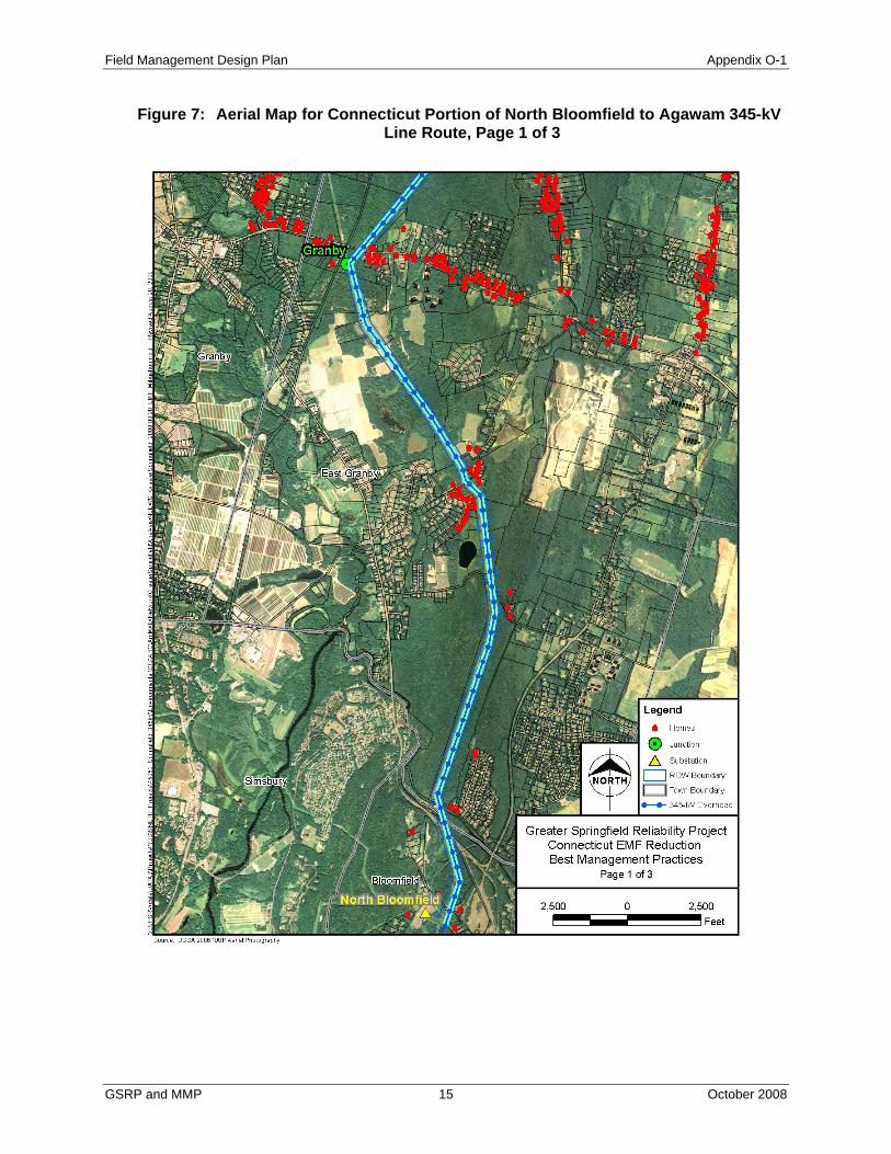
Field Management Design Plan Appendix O-1
Figure 7: Aerial Map for Connecticut Portion of North Bloomfield to Agawam 345-kV Line Route, Page 1 of 3
GSRP and MMP 15 October 2008

Field Management Design Plan Appendix O-1
Figure 8: Aerial Map for Connecticut Section of North Bloomfield to Agawam 345-kV Line Route, Page 2 of 3
GSRP and MMP 16 October 2008

Field Management Design Plan Appendix O-1
Figure 9: Aerial Map for Connecticut Section of North Bloomfield to Agawam 345-kV Line Route, Page 3 of 3
II.7 CROSS SECTIONS FOR THE CONNECTICUT SECTION OF GSRP
The following cross sections are provided for reference to the various alternate configurations.
GSRP and MMP 17 October 2008

Field Management Design Plan Appendix O-1
Note: This page was intentionally left blank.
GSRP and MMP 18 October 2008

Field Management Design Plan Appendix O-1
Figure 10: XS-2 Cross Section, Base Configuration
GSRP and MMP 19 2008

Field Management Design Plan Appendix O-1
Note: This page was intentionally left blank.
GSRP and MMP 20 2008

Field Management Design Plan Appendix O-1
Figure 11: XS-2 Cross Section, Alternate 1 Configuration
GSRP and MMP 21 2008

Field Management Design Plan Appendix O-1
Note: This page was intentionally left blank.
GSRP and MMP 22 2008

Field Management Design Plan Appendix O-1
Figure 12: XS-2 Cross Section, Alternate 2 Configuration
GSRP and MMP 23 2008

Field Management Design Plan Appendix O-1
Note: This page was intentionally left blank.
GSRP and MMP 24 2008

Field Management Design Plan Appendix O-1
Figure 13: XS-2 Cross Section, Alternate 3 Configuration
GSRP and MMP 25 2008

Field Management Design Plan Appendix O-1
Note: This page was intentionally left blank.
GSRP and MMP 26 2008

Field Management Design Plan Appendix O-1
Figure 14: XS-2 Cross Section, Alternate 4 Configuration
GSRP and MMP 27 2008

Field Management Design Plan Appendix O-1
Note: This page was intentionally left blank.
GSRP and MMP 28 2008
Field Management Design Plan Appendix O-1
Figure 15: XS-2 Cross Section, Alternate 5 Configuration
GSRP and MMP 29 2008

Field Management Design Plan Appendix O-1
Note: This page was intentionally left blank.
GSRP and MMP 30 2008

Field Management Design Plan Appendix O-1
Figure 16: XS-2 Cross Section, Alternate 6 Configuration
GSRP and MMP 31 2008

Field Management Design Plan Appendix O-1
Note: This page was intentionally left blank.
GSRP and MMP 32 2008

Field Management Design Plan Appendix O-1
Figure 17: XS-2 Cross Section, Alternate 7 Configuration
GSRP and MMP 33 2008

Field Management Design Plan Appendix O-1
Note: This page was intentionally left blank.
GSRP and MMP 34 2008

Field Management Design Plan Appendix O-1
III. MANCHESTER TO MEEKVILLE JUNCTION CIRCUIT SEPARATION PROJECT
III.1 PROJECT DESCRIPTION AND BASE LINE DESIGN
The Manchester to Meekville Junction Circuit Separation Project (MMP) consists of separating a 115-kV
circuit and a 345-kV circuit, which are currently installed on shared lattice-steel towers, by replacing the
115-kV circuit on a new line of single-circuit steel monopole structures within the existing ROW. This
project requires line work on a 2.2-mile section of the ROW between Manchester Substation and
Meekville Junction, a ROW that is approximately 350 feet wide. On this ROW there are currently two
lines of double-circuit lattice-steel towers supporting one 345-kV circuit and three 115-kV circuits. Also,
a double-circuit distribution line is located between the two transmission lines on portions of this ROW.
No ROW expansion is anticipated for the project as the relocated 115-kV circuit can be placed on new
monopole structures located between the existing lattice-steel tower lines.
III.2 FOCUS AREAS FOR MAGNETIC FIELD MANAGEMENT
Per the CSC BMP, the focus areas for applications of low-cost magnetic field management designs are
those locations where public or private schools, licensed child day-care facilities, public playgrounds,
licensed youth camps, or residential areas are adjacent to a proposed new transmission line. For the
MMP, there are no youth camps, child day-care facilities, or residential areas adjacent to the transmission
line ROW, but one school and one playground are adjacent on the east side. Maps in Volume 9 of the
Application illustrate the locations of these facilities along the MMP Line Route.
GSRP and MMP 35 2008

Field Management Design Plan Appendix O-1
III.3 BASE MMP LINE DESIGN AND ALTERNATIVE MMP LINE DESIGNS FOR MAGNETIC FIELD REDUCTIONS IN FOCUS AREAS
III.3.1 115-kV Vertical Line Configuration Using 345-kV Class Insulation, Conductor Bundles and Phase Spacings, and Best Circuit Phasing, the Base Line Design
Vertical line structures, as shown in Figure 18, are typically used in areas with narrower ROW widths or
where several lines are needed on the same ROW, as is the case for MMP. This type of line would be
constructed using steel monopoles on concrete pier foundations. Typical costs for this configuration at
two average structure heights are included in Table 8. The base case line design would employ 345-kV
class insulation, conductor bundles and phase spacings, as does the majority of the existing 115-kV circuit
section it would replace. This design has been considered to provide a method of potentially converting
this line to 345-kV at a future date. The base case vertical line design would also employ a no-cost
optimal circuit phasing with respect to the existing lines continuing in use, as a magnetic field reduction
strategy.
Table 8: Typical Vertical Line Costs Per Span
Figure 18: Tangent Vertical Structure
Cost Per Mile Structure
Description Total 155' Vertical $5,497,000 Note: Structure Costs are based on (10) structures per mile ((8) tangents, (1) angle, (1) DE); Conductor costs are based on (2) - 1590-kcmil ACSR "Lapwing"; Costs include labor, material, and hardware
*
GSRP and MMP 36 2008

Field Management Design Plan Appendix O-1
III.3.2 Modifications to the Existing Line Separating the 115-kV circuit from the 345-kV line’s structures allows an additional opportunity to
reduce edge-of-ROW magnetic fields over the entire 2.2-mile MMP route, including opposite to the focus
area facilities. This can be accomplished by re-using the former 115-kV circuit conductors on the
existing 345-kV line towers to form a bundled 345-kV circuit, and the phasing of the conductors could
also be arranged to form a split-phase line configuration.
The bundled circuit configuration of the 345-kV line reduces the current in the existing 345-kV line
conductors, which are nearest to the east edge of ROW. This modification alone would reduce the
magnetic fields at the east edge-of-ROW. By reverse phasing the bundled circuit conductors to form a
split-phase line configuration, magnetic fields will be reduced to a larger degree, and at both ROW edges.
In order to implement the split-phase line configuration, a length of about 3,500 feet of the existing 115-
kV line conductors and insulators must be replaced with bundled conductors and 345-kV class insulation.
For the split-phase line configuration, conductor ties between the middle conductor bundles and between
the opposite-side top and bottom conductor bundles will be required at both ends of the 2.2-mile segment.
III.3.3 Other Line Configurations The vertical line configuration is the only line design that can be placed in between the existing lattice
tower lines and still provide proper electrical clearance to allow for safe operation and maintenance of the
line. While there is sufficient room to install a delta line design on the west side of the ROW, positioning
a line closer to the west edge of the ROW will increase field levels on that edge of the ROW.
III.3.4 Conductor Heights Above Ground CL&P calculates magnetic fields using typical conductor heights above ground at the middle of cross-
country line spans. Wherever conductor heights are higher above ground (e.g., over I-84), magnetic fields
will be lower at the ground level on and immediately adjacent to the ROW. Because conductor heights
GSRP and MMP 37 2008

Field Management Design Plan Appendix O-1
above ground increase between the mid-span points and the line structures, magnetic field levels will be
lower than CL&P’s calculated values at ROW edge locations which are not opposite the mid-span points.
III.3.5 Conductor Separation Reducing the separation distance between each of the three conductor bundles of a 345-kV line can
reduce magnetic field levels. However, reducing the conductor separations below CL&P’s standard
separations for each 345-kV line design can reduce reliability and make it unsafe for line workers to
perform live-line maintenance. In this instance, however, the proposed new line could be built with
standard 115-kV conductor separations, sacrificing the ability to use this line section at 345 kV in the
future. Doing so, however, would minimally affect magnetic field levels at the ROW edges. As such,
CL&P is not considering any use of reduced conductor separations in this Plan.
III.3.6 Shifting the ROW or Alignments of Lines on a ROW Under certain circumstances, an entire ROW could be shifted to provide additional distance between the
new lines and adjacent facilities, thereby reducing magnetic fields at these facilities. This is seldom a
practical or low-cost option as it would require purchasing new easements and would result in a proposal
of lines on new ROW when the existing ROW could be more than adequate to construct a proposed new
line.
Shifting line alignments on a ROW is also seldom a practical or low-cost magnetic field management
option. Doing this where the ROW is wide enough for a future line addition will make that future line’s
construction on the ROW difficult without reworking the line shift. This is not a practical option for
MMP.
III.3.7 Passive Loop Shielding Magnetic field reduction can be achieved over small areas with wire loops installed parallel to overhead
lines, for example along a ROW edge. Such loops can be designed such that the magnetic fields produced
GSRP and MMP 38 2008

Field Management Design Plan Appendix O-1
by currents induced in the loop conductors partially cancel the transmission line magnetic fields resulting
in a decreased magnetic field at the edge of right-of-way. The area of reduced magnetic fields near to
passive loops is relatively small, and the additional structures and wires add visual impact. For these
reasons, CL&P does not consider passive loop shielding to be a practical field-management tool over any
portion of the 2.2-mile ROW length between Manchester Substation and Meekville Junction.
III.4 MAGNETIC FIELD LEVELS PRODUCED BY THE BASE LINE DESIGN AND ALTERNATIVE LINE DESIGNS
Exponent calculated magnetic fields for the right-of-way cross-section over a 2.2-mile section of the
ROW between Manchester Substation and Meekville Junction in Manchester, Connecticut according to
recognized industry practice (i.e., typical minimum mid-span clearance of conductors to ground, 1 meter
above ground, assumption of flat terrain and balanced currents). These calculations were made at three
New England system load levels estimated by CL&P to occur in the year 2017, specifically the annual
average load, the annual peak load, and the peak-day average load. Please refer to Section O of the CSC
Application for the assumptions that were made in system load-flow modeling to determine the line
currents over this ROW section for each of the three load levels.
Table 9 shows the difference in calculated magnetic field levels at the edges of ROW for the existing
conditions and the post-NEEWS conditions with the base case line design. The circuit separation and
phasing change in this ROW alone reduces the edge of ROW magnetic field levels, by 33% on the
westerly edge and by 55% on the easterly edge.
GSRP and MMP 39 2008

Field Management Design Plan Appendix O-1
Table 9: Magnetic Field Comparison, Pre- and Post-NEEWS Configurations on MMP ROW
West ROW Edge
East ROW Edge
Level (mG)
Level (mG)
Pre-NEEWS 62.3 4.8 27.4Post-NEEWS - Base Line Design 30.0 3.2 12.2
XS-21 Cross Section Configuration
Average Annual Load Case
Maximum Level on ROW (mG)
Table 10 shows calculated edge-of-ROW magnetic field levels along the entire 2.2-mile section of the
ROW between Manchester Substation and Meekville Junction. Relative to the edge-of-ROW magnetic
field levels of the base line design, the table also shows the percentages by which these edge-of-ROW
magnetic fields would be reduced for three alternative line designs, and the table shows the extra cost
associated with each of these line designs.
Table 10: Magnetic Field Management Results for MMP ROW
Level (mG)
Reduction (%)
Level (mG)
Reduction (%)
Section Amount ($)
Project Increase (%)
Base Line Design - Vertical 30.0 3.2 - 12.2 - 13,728,000 -Alt 1 - Vertical +20 feet 29.0 3.1 3% 12.2 0% 3,252,000 23.7%
Alt 2 - 395 Bundled Circuit 34.4 3.4 -6% 10.6 13% 520,000 3.8%Alt 3 - 395 Split Phase 34.1 2.4 25% 4.8 61% 520,000 3.8%Alt 4 - 115-kV Design 29.0 2.8 13% 12.1 1% -2,557,000 -18.6%
XS-21 Cross Section Configuration
Average Annual Load Case CostMaximum Level on
ROW (mG)
West ROW Edge East ROW Edge
Aerial map Figure 7 provides a graphical representation of the calculated magnetic field levels over the
right-of-way cross section for the line segment between Manchester Substation and Meekville Junction,
for the annual average load case. This graph includes the base line vertical configuration and the four
design variations considered
GSRP and MMP 40 2008

Field Management Design Plan Appendix O-1
Figure 19: Magnetic Field Profiles for Potential Reduction Section on MMP
The table shows that reconfiguring the existing 345-kV circuit as a split-phase line will be the most
effective at reducing magnetic field levels at the edges of the ROW. For the MMP, the cost of this option
is within the 4% guideline and provides a reduction greater than 15% at the ROW edges. Reconfiguring
the 345-kV circuit into a bundled circuit configuration reduces magnetic field levels on one edge of the
ROW but increases levels on the other edge. Again, a split-phase line configuration for the 345-kV
circuit will be the most effective method of reducing magnetic field levels at the edges of the ROW.
III.5 CL&P RECOMMENDATION FOR THE 2.2-MILE MMP ROW SEGMENT
Alternative line designs for magnetic field reductions that cause safety or reliability consequences, do not
achieve magnetic field reductions of at least 15% on both edges of the ROW, or that interfere with the
ability of the ROW to accept future lines will not be recommended. The only remaining line design
alternative is the split-phase line configuration of the existing 345-kV line. The split-phase line
GSRP and MMP 41 2008

Field Management Design Plan Appendix O-1
GSRP and MMP 42 2008
configuration can be implemented without increases to social or environmental impacts. The existing
lattice-steel towers already support a double-circuit line configuration that can be easily modified to a
split-phase line configuration by re-conductoring and re-insulating several spans of the existing 115-kV
circuit. Therefore, CL&P recommends the existing 345-kV split-phase line design option on this ROW
segment.
Should the CSC in its balancing of impacts and mitigation conclude that the base line design or any of the
other line design alternatives examined in the Plan are preferable, CL&P is prepared to build any of these
line designs over the 2.2-mile segment.
III.6 CROSS SECTIONS FOR THE MMP
The following cross sections are provided for reference to the various alternate configurations.

Field Management Design Plan Appendix O-1
Figure 20: XS-21 Cross Section, Base Configuration
GSRP and MMP 43 2008

Field Management Design Plan Appendix O-1
Note: This page was intentionally left blank.
GSRP and MMP 44 2008

Field Management Design Plan Appendix O-1
Figure 21: XS-21 Cross Section, Alternate 1 Configuration
GSRP and MMP 45 2008

Field Management Design Plan Appendix O-1
Note: This page was intentionally left blank.
GSRP and MMP 46 2008

Field Management Design Plan Appendix O-1
Figure 22: XS-21 Cross Section, Alternate 2 Configuration
GSRP and MMP 47 2008

Field Management Design Plan Appendix O-1
Note: This page was intentionally left blank.
GSRP and MMP 48 2008

Field Management Design Plan Appendix O-1
Figure 23: XS-21 Cross Section, Alternate 3 Configuration
GSRP and MMP 49 2008