Field Evaluation of the Multi-Depth Deflectometers
56
. TECHNICAL REPORT STANDARD TITLE PAGE 1. Report No. 2, Govl'frlmenl Acce.lion No. 3. Recipient's Catalog No. FHWA/TX-88/1123-2 .to Ti'l. and Sublitle S. Report Dol • Field Evaluation of the Multi-Depth Deflectometers SeQtember· 1988 6. p.',forming Orgonllo'ion Code .' 7. Author' 5J 8. P.rforming Organization Repor' No. T. Scull ion, J. Uzan, J. r. Yazda.ni, and Paul Ch1\n Resea.rch Report 1123-2 9. Performln; Orgon; ration Name and Address 10. Wo,iI Unit No. Texas Transportation Institute 11. Con'roet or Grant No. The Texas A&M University System Studv No, 2-i8-87-1123 College Station, Texas 77843-3135 13. Type of R.porl and P.riod Cover.d 12. Sponsoring Agency Nome Qnd Address September 1986 , Texas State Department of Highways and Pub1 ic Interim - September 1988 Transportation; Transportation Planning Division u. Sponloring Agency Cod. g.O . . Box 5051 ustln Texas 78763 IS. SUP,plemenlor" No'.' Research performed in cooperation with DOT, FHWA. Research Study Title: Nondestructive Test Procedures for Analyzing the Structural Condi.tibn of 16. Ab,'ra-cl The Multi-Depth Deflectometer (MDD) is an LVDT deflection measuring device is retrofitted into pavement layers. A maximum of six MDD modules may be installed in a single 1.5 inch diameter hole. The modules are clamped against the sides of the hole at the required depths and the center core is. attached to an anchor located approximately 7 feet below. the pavement surface. The MDD can measure either the .. lative elastic deflection or the total permanent deformation of each layer in the pave ment system. By placing multiple modules in a single hole, the vertical strains in- duced in pavement layers can be measured. This report describes the installation of Multi-Depth Deflectometers at the Texas A&M Research Annex. The pavement response under both Falling Weight Deflectometer and truck loading is described, together with an analysis procedure to backcalculate layer moduli from depth deflection readings. The MDD results obtained are extremely promising. The device is relatively inexpensive and durable. It shows a great potential in ass isti ng in several areas of pavement research, including backcalculationanalysis, tire pressure and rutting studies. 17. Key Word, 18. Distribution S •• t..,.." Multl-Depth Deflectometer, No restrictions. This document is aV1\il1\ble Pavement Instrumentation, Deflection, to the publ ic through the Nationa.l Technica.l Modulus Backcalculation Information Service, 5285 Port Royal Road Spri ngfi e1d, Virginia 22161 19. Sec"rity Clauif. (of this report) 20. Security Claud. (of thi. page) 21. ND. of Page. 22. Price Unclassified Unclassified 55 Form DOT F 1700.7 '".111
Transcript of Field Evaluation of the Multi-Depth Deflectometers

. TECHNICAL REPORT STANDARD TITLE PAGE
1. Report No. 2, Govl'frlmenl Acce.lion No. 3. Recipient's Catalog No.
FHWA/TX-88/1123-2 .to Ti'l. and Sublitle S. Report Dol •
Field Evaluation of the Multi-Depth Deflectometers SeQtember· 1988 6. p.',forming Orgonllo'ion Code
.'
7. Author' 5J 8. P.rforming Organization Repor' No.
T. Scull ion, J. Uzan, J. r. Yazda.ni, and Paul Ch1\n Resea.rch Report 1123-2 9. Performln; Orgon; ration Name and Address 10. Wo,iI Unit No.
Texas Transportation Institute 11. Con'roet or Grant No. The Texas A&M University System Studv No, 2-i8-87-1123 College Station, Texas 77843-3135
13. Type of R.porl and P.riod Cover.d
12. Sponsoring Agency Nome Qnd Address September 1986
, Texas State Department of Highways and Pub1 ic Interim - September 1988 Transportation; Transportation Planning Division u. Sponloring Agency Cod. g.O . . Box 5051
ustln Texas 78763 IS. SUP,plemenlor" No'.' Research performed in cooperation with DOT, FHWA. Research Study Title: Nondestructive Test Procedures for Analyzing the Structural
Condi.tibn of P~ve 16. Ab,'ra-cl
The Multi-Depth Deflectometer (MDD) is an LVDT deflection measuring device \~hich is retrofitted into pavement layers. A maximum of six MDD modules may be installed in a single 1.5 inch diameter hole. The modules are clamped against the sides of the hole at the required depths and the center core is. attached to an anchor located approximately 7 feet below. the pavement surface. The MDD can measure either the re~ ..
lative elastic deflection or the total permanent deformation of each layer in the pave ment system. By placing multiple modules in a single hole, the vertical strains in-duced in pavement layers can be measured.
This report describes the installation of Multi-Depth Deflectometers at the Texas A&M Research Annex. The pavement response under both Falling Weight Deflectometer and truck loading is described, together with an analysis procedure to backcalculate layer moduli from depth deflection readings. The MDD results obtained are extremely promising. The device is relatively inexpensive and durable. It shows a great potential in ass isti ng in several areas of pavement research, including backcalculationanalysis, tire pressure and rutting studies.
17. Key Word, 18. Distribution S •• t..,.."
Multl-Depth Deflectometer, No restrictions. This document is aV1\il1\ble Pavement Instrumentation, Deflection, to the publ ic through the Nationa.l Technica.l Modulus Backcalculation Information Service, 5285 Port Royal Road
Spri ngfi e 1 d, Virginia 22161
19. Sec"rity Clauif. (of this report) 20. Security Claud. (of thi. page) 21. ND. of Page. 22. Price
Unclassified Unclassified 55 Form DOT F 1700.7 '".111

FIELD EVALUATION OF THE
KIlLTI - DEPTH DEFLECTOMETERS
by
T. Scullion J. Uzan
J. I. Yazdani P. Chan
Research Report 1123-2
Study Title: "Nondestructive Test Procedures for Analyzing the Structural Condition of Pavements"
Project 2-18-87-1123
Sponsored by
Texas State Department of Highways and Public Transportation
in cooperation with
u.S. Department of Transportation Federal Highway Administration
by
Texas Transportation Institute
September, 1988

METRIC (SI*) CONVERSION FACTORS APPROXIMATE CONVERSIONS TO SI UNITS
Symbol Whon You Know Multiply By To Find
In fI yd mi
In' fI' yd' mil ac
oz Ib T
Iloz gal
fI' yd'
inches leet yards miles
square inches square, teet
square yards square miles acres
LENGTH
2.54 0.3048
0.914 1.61
AREA
645.2 0.0929
0.836 2.59 0.395
millirnetres metres
metres -kilometres
millimetres squared metres squared metres squared kilometres squared hectares
MASS (weight)
ounces 28.35 pounds 0.454 short tons (2000 Ib) 0.907
fluid ounces gallons cubic leet cubic yards
VOLUME
29.57 3.765 0.0328 0.0765
grams kilograms megagrams
millilitres litres metres cubed metres cubed
NOTE: Volumes greater than 1000 L shall be shown in rna.
TEMPERATURE (exact)
OF Fahrenheit 5/9 (after Celsius temperature subtracting 32) temperature
* SI Is the symbol for the International System of Measurements
Symbol
mm m
m km
mm' m' m' km' ha
g kg Mg
mL L
m' m'
~ -
•
•
APPROXIMATE CONVERSIONS TO SI UNITS Symbol When You Know Multiply By To Find
mm m m
km
mm' m' km' ha
g kg Mg
mL L m' m'
millimetres metres metres kilometres
LENGTH
0.039 3.28
1.09 0.621
AREA
millimetres squared 0.0016 metres squared 10.764 kilometres squared 0.39 hectore. (10000 m') 2.53
inches feet yards miles
square inches square feet square miles acres
MASS (weight)
grams 0.0353 kilograms 2.205
megagrams (1 000 kg) 1.103
millilitres lUres metres cubed metres cubed
VOLUME
0.034 0.264 35.315 1.308
ounces pounds short tons
fluid ounces gallons cubic feet cubic yards
TEMPERATURE (exact)
°C Celsius 9/5 (then Fahrenheit temperature temperature add 32)
OF 98.6 -40 0
I ' , , , ',' -40 1_ 20
°C
, , ~, ~ ,1~0, I ,1~, 1
, i " 'i 20 40 60 60
37
OF 212
,2?O,I , 100
oc These factors conform to the requirement of FHWA Order 5190.1A.
SYmbol
in ft
yd mi
oz Ib T
floz gal ft' yd'

ABSTRACT
The Multi-Depth Deflectometer (MDD) is an LVDT deflection measuring device which is retrofitted into pavement layers. A maximum of six MDD modules may be installed in a single 1.5 inch diameter hole. The modules are clamped against the sides of the hole at the required depths and the center core is attached to an anchor located approximately 7 feet below the pavement surface. The MDD can measure either the relative elastic deflection or the total permanent deformation of each layer in the pavement system. By placing multiple modules in a single hole, the vertical strains induced in pavement layers can be measured.
This report describes the installation of Multi-Depth Deflectometers at the Texas A&M Research Annex. The pavement response under both Falling Weight Deflectometer and truck loading is described, together with an analysis procedure to backcalculate layer moduli from depth deflection readings. The MDD results obtained durable. research
are extremely promising. The device is relatively inexpensive and It shows a great potential in assisting in several areas of pavement
including backcalculation analysis, tire pressure and rutting studies.
i

DISCLAIMER
This report is not intended to constitute a standard, specification or a regulation and does not necessarily represent the views or policy of the Federal Highways Administration or Texas Department of Highways and Public Transportation.
i i

IMPLEMENTATION STATEMENT
The Multi-Depth Deflectometer can assist the SDHPT in many areas. Studies planned include validation of modulus backcalculation procedures and monitoring the effects of wide base single tires. Both of these should provide information that can be implemented with the Department's ongoing pavement management effort.
iii

TABLE OF CONTENTS
Abstract ... Disclaimer ...... . Implementation Statement Table of Contents List of Figures List of Tables. Section 1 Introduction Section 2 Description of MDD Unit
2.1 Field Installation 2.2 Field Calibration. 2.3 MDD Recovery
Section 3 Data Logging System of the MDD 3.1 Signal Conditioner Box 3.2 Microcomputer Data Logging 3.3 Data Cleanup and Scaling
Section 4 Data Analysis ........ .
Section 5 References
4.1 Typical Results under FWD Loading 4.2 Typical Results under Truck Loading 4.3 Modulus Backcalculation Conclusions
iv
Page
i
i i
iii iv
v vi
1
3 7
11
13 14 14 14 16
19
19
23 27
45
47

LIST OF FIGURES
Figure
I Components of an MDD Module .... 2 Typical Cross Section of MDD after Installation 3 Photograph of MDD Module ........... . 4 Set-Up of Drilling Procedure for MDD Installation 5 MDD Hole Ready for Module Installation ..... . 6 Lowering the MDD Module by Means of Snap Connector 7 Field Calibration of MDD .. . 8 MDD Data Logging System .. . 9a MDD Response Before Filtering 9b ·MDD Response after Filtering.
10 MDD Installations at TTl Research Annex II MDD Response Under FWD Loading (Section 12) 12 MDD Response Under FWD Loading (Section 8) . 13 Vertical Compressive Strains in Granular Base 14 MDD Response to Truck Loading ..... . 15 MDD Deflection Bowl Under Truck Loading . 16 Comparison of Measured Against Calculated
Deflection with Depth ......... . 17 Manual Iterative Procedure for Matching Measured and
Calculated relative Depth Deflections . 18 Input Screen to MDD Analysis Program .. 19 Output Report from MDD Analysis Program
v
Page
4 5
6
8
9
10 12 15 18 18 20 21 22 24 28 29
31
32 37 38

Tables
1 2
3
4
5a
5b
6a
6b
7a
7b
8
9
LIST OF TABLES
Repeatability Measurements on Section 11 at 8500 lb. Load Level. Repeatability Measurements on Section 11 at 16,000 lb. Load Level ...... . FWD and MDD Maximum Deflection Section 8
FWD and MDD Maximum Deflection Section 12 Moduli Automatically Calculated from MDD (Section 8) Semi-Infinite Subgrade . . . . , . . . . . . . . . . . . . . . . . . . . . . Moduli Automatically Calculated from MDD Bedrock at 250 Inches Moduli Automatically Calculated from MDD (Section 12) Semi-Infinite Subgrade ................... . Moduli Automatically Calculated from MDD (Section 12) Bedrock at 250 Inches . . . . . . . . . . . . . . . . . . . . . . . . . . Moduli Automatically Calculated from MDD (Section 12) 3-Layer System Semi-Infinite Subgrade ............... . Moduli Automatically Calculated from MDD (Section 12) 3-Layer System - Bedrock at 250 Inches . . . . . . Comparing FWD and MDD Layer Moduli (Section 8) .
Comparing FWD and MDD Layer Moduli (Section 12)
vi
Page
25
26 33 34
39
39
40
40
41
41
43
44

SECTION 1
INTRODUCTION
This report describes the Multi-Depth Deflectometer (MDD) and presents results
obtained from three instrumented pavement sections at the Texas A&M Research
Annex. The MDD measures both transient deflections and permanent deformations of
pavement layers. It has been used to measure in-situ resilient moduli values of
pavement layers and to identify individual layer deformations in accelerated
loading tests. The main goal of this report is to: (a) describe the MDD and the
installation process; (b) show typical results under truck and Falling Weight
Deflectometer loadings; and (c) develop an approach to assist in validating
modulus backcalculation procedures under Nondestructive Testing.
The procedure used by several investigators to verify modulus backcalcula
tion procedures is to compare the results obtained from an appropriate theoreti
cal analysis of NonDestructive Test (NDT) data to those obtained from laboratory
testing of the pavement materials. Resilient modulus tests are commonly per
formed on base course and subgrade materials using a triaxial test apparatus.
For thin surfacings, repeated load diametral tests are performed. The problem
with this approach is that it is difficult, if not impossible, to duplicate field
loading conditions in the laboratory. The problem is particularly acute for
granular base materials, where laboratory specimens have to be remolded to the
Same moisture and density as in the field and then sUbjected to loading condi
tions as close as possible to those under moving vehicles. Despite the problems
inherent in this approach, verification of modulus backcalculation procedures
remains a crucial concern, particularly with the publication of the new AASHTO
Design Procedure (1) which advocates NDT evaluations for pavement rehabilitation
designs.
In this report a different approach is taken to verify modulus backcalcula
tion procedures. Three research pavement sections at the Texas Transportation
Institute's Research Annex have been instrumented with Multi-Depth Deflectometers
(MDD). These devices measure the transient deflection between a particular
location in the pavement and an anchor located at approximately 7 feet below the
surface. By placing MDDs in each pavement layer, a procedure has been developed
to independently calculate the resilient modulus of each pavement layer.
I

Therefore by measuring MDD response under Falling Weight Deflectometer (FWD)
loading, two independent procedures are available for backcalculating layer
modulus, one with the FWD sensor readings and the other with the MOD output.
Results are presented in this paper of MOD response measured at a range of
Falling Weight Deflectometer loadings. Analysis included developing an automated
procedure for estimating layer moduli from MDD readings and comparing these
results with those obtained using standard procedures available for interpreting
surface deflections.
Preliminary results of MDD response under truck loading are also presented.
The MOD shows considerable potential in this area. By processing the signal, it
is possible to determine the vertical strains in the base course, the vertical
strains in the subgrade, and the surface curvature index (related to the tensile
strains at the bottom of the asphalt). Furthermore, by measuring the zero
voltage position of each MOD module from the surface, it is possible to monitor
permanent deformations in each of the pavement layers.
In the next section of this report, the MOD device and the instrumentation
procedure will be described. The Data Logging System is presented in Section 3,
which is the followed by a section on the typical results obtained and analysis
performed. Conclusions are presented in Section 5.
2

SECTION 2
DESCRIPTION OF MDD UNIT
The Multi-Depth Deflectometer (MDD) was developed by the National Institute
for Transport and Road Research (NITRR) in South Africa (2, 3, 4) as an integral
part of their accelerated loading tests. It is used to measure transient
deflection and the permanent deformation in pavement layers. It provides a means
of measuring the change in pavement deflection at various depths in a vertical
direction caused by a passing wheel load, generating a depth deflection profile.
The permanent deformation of a pavement at different layer depths can also be
measured during the service period of the MDD. The MDD is so constructed that
the resilient deflection of a maximum of six levels can be simultaneously
measured. The installation of the MDD is an intricate procedure and is described
in Section 2.1.
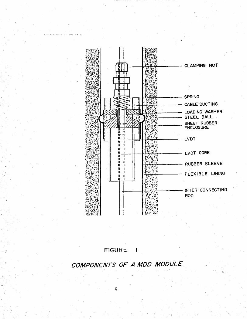
Figure 1 shows a schematic of a typical MDD which consists of modules with
Linear Variable Differential Transformers (LVDTs). The LVDTs are positioned at
different depths in the pavement to measure any movement in these layers. The
modules are locked in position by turning the clamping nut which forces the
steel ball outwards, clamping them against the sides of the hole. The intercon
necting rod is adjustable and contains LVDT cores at spacings which coincide with
the module placement.
A typical MDD installation is shown in Figure 2. In practice up to six
modules may be placed in a single hole. The interconnecting rod is fixed to an
anchor located at approximately 7 feet below the pavement surface. When data is
being collected, a reinforced connector cable is attached which links to the
data-capture system. When the MDD is not in use, a brass surface cap, which is
flush with the surface, completely seals the hole.
Figure 3 shows a photograph of the MDD Module with the Schaevitz E-300 (0.30
inch equals 10 volts) series LVDT. The total length of the module is approxi
mately 5 inches. If the E-IOO (0.10 inch equals 10 volts) series LVDT is used,
the total length drops to 4 inches. The length of the module is the only factor
which dictates how close the modules can be placed within the pavement layers.
In order for the MDD to operate satisfactorily, certain mechanical and
electrical requirements have to be met. Mechanical requirements include the
3
I I IL.
FIGURE
COMPONENTS OF A MDD MODULE
4
LVDT CORE
RUBBER SLEEVE
INTER CONNECTING ROD

CONNECTOR CONNECTOR CABLE
8 FT.
1
POLYURETHANE CASTING COMPOUND
FLEXIBLE SURFACE CAP
MULTIDEPTH DEFLECTOMETER MODULE
SNAP CONNECTOR
.... ~I\lf\1"" HEAD (POSITIVE LOCKING)
ANCHOR EXTENSION
Not to Scale
~---------ANCHOR
Figure 2. Typical Cross Section of MDD after Installation 5

Figure 3. Photograph of MDD Module
6

Figure 4. Set-up of Drilling Procedure for MDD Installation
8

.following:
the MDD should be inserted in a hole drilled vertically with a diameter
of about 1.5 inches.
the material adjacent to the hole should remain undisturbed.
the hole must be lined so as not to dislodge material from the sidewalls
when the pavement is under stress.
the test hole must later be sealed so as not to allow the ingress of any
moisture.
Among the electrical requirements to be met are the following:
the response of the module must be insensitive to moisture in the test
hole.
LVDTs are used to measure the pavement deflections.
the cables used to transmit data must be fixed in a protective sleeve.
prior to operation, the LVDTs must be calibrated, so as to remove any
zero error.
2.1 FIELD INSTALLATION
In order for the MDD to operate effectively, special care has to be exer
cised in installing the MDD unit. The test hole for instrumentation of the
pavement section has to be drilled vertically. Percussion drills and a specially
designed drilling rig are used for the drilling. procedure (Figure 4). A 1.5 inch
diameter hole is drilled to a depth of approximately 7 feet. The top one inch of
the pavement is drilled with a special 2.5 inch drilling bit for installation of
the top cap which is mounted flush with the surface (Figure 5). The top of the
MDD has to be level with the pavement to avoid any point loading on it after
installation. The hole is then lined with a 0.1 inch thick lining tube and the
voids between the tube and the wall are filled with a rubber grout. The lining
tube serves two purposes: viz, preventing the adjacent material from dislodging
when under stress and guiding the MDD anchorpin for correct installation. The
MDD anchorpin is locked in place using a fast setting cement/sand paste. This is
fol10we~ by installing a pilot rod which is used to guide the MDD modules into
the right position.
The modules are installed into the correct predetermined position using an
installation tool especially designed for the purpose. Figure 6 shows a module
being lowered into the test hole. The module is guided to the correct position
7

Figure 5. MOO Hole Ready for Module Installation
9

Figure 6. Lowering the MDD Module by Means of Snap Connector
10

in the test hole and secured by turning the clamping nut at the top of the MDD
module. Similarly all the other modules are installed. The modules are numbered
from the shallowest to the deepest in ascending order. The modules having been
fixed in place, they must be calibrated before their operation. The complete
installation takes approximately 1 1/2 days. The hole is drilled, lined and the
anchor is installed on the first day; the rubber grout needs approximately 12
hours to set (depending on the temperature). On the second day the MDD modules
are installed and calibrated.
2.2 FIELD CALIBRATION
In order to perform field calibration, a signal conditioner box unit, and a
calibrator unit fitted with a dial gauge mounted on a screw adjusting mechanism
are used, as shown in Figure 7. The gain pot settings on the signal conditioner
are adjusted for each module to be the same as obtained from calibration in the
laboratory. The MDD core is moved up and down against the modules manually to
determine its mid-zero position. The calibrator unit is then placed above the
MDD hole and a core is connected to it. The screw mechanism is turned until the
module reads zero on the conditioner unit. The dial gauge is set to a zero
reading, and the screw mechanism is turned until the dial gauge reads 0.30 inch,
(for the E300 Schaevitz LVDTs). The conditioner unit should read 10 (volts). If
not, it should be adjusted to read 10.00 volts on the conditioner. As a check,
the dial gauge is reset to zero displacement, and the conditioner should give a
zero reading. The procedure is repeated for each module installed in the MDD.
Upon completion of the calibration procedure, the final pot settings are noted.
Either the E300 series LVDT with a range of 0.30 inch or the EIOO series LVDT
with a range 0.10 inch has been used. The EIOO LVDTs are recommended for
deflection evaluation, whereas the E300 are preferred for long-term monitoring
under traffic.
After having calibrated the MDD, it is sealed off with a brass cap which is
screwed flush with the pavement surface. The surface cap is removed during a
measuring operation to enable a cable to be connected from the MDD to a compu
terized data acquisition system. This setup was shown earlier in Figure 2.
11
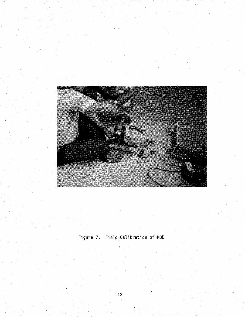
Figure 7. Field Calibration of MOD
12

2.3 MDD RECOVERY
One of the major advantages of the MDD is that the modules can be extracted
from the hole once testing is complete. With reference to Figure 2, the only
parts of the system which cannot be extracted are the anchor and hole lining.
The MDD modules, center core, snap head connector and surface cap can be recov
ered for future use. Replacing MDD modules in an existing hole can be accom
plished in one day.
13
SECTION 3
DATA LOGGING SYSTEK OF THE KDD
The MDD data logging system is shown schematically in Figure 8. Loads are
applied to the system by either Nondestructive Testing Equipment or truck tire
loadings. The LVDTs monitor the differential movement between the pavement
layers and the fixed anchor. The LVDT output voltage is processed using the
following hardware and software.
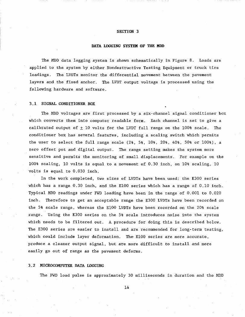
3.1 SIGNAL CONDITIONER BOX
The MDD voltages are first processed by a six-channel signal conditioner box
which converts them into computer readable form. Each channel is set to give a
calibrated output of ± 10 volts for the LVDT full range on the 100% scale. The
conditioner box has several features, including a scaling switch which permits
the user to select the full range scale (2%, 5%, 10%, 20%, 40%, 50% or 100%), a
zero offset pot and digital output. The range setting makes the system more
sensitive and permits the monitoring of small displacements. For example on the
100% scaling, 10 volts is equal to a movement of 0.30 inch, on 10% scaling, 10
volts is equal to 0.030 inch.
In the work completed, two sizes of LVDTs have been used: the E300 series
which has a range 0.30 inch, and the EIOO series which has a range of 0.10 inch.
Typical MDD readings under FWD loading have been in the range of 0.001 to 0.020
inch. Therefore to get an acceptable range the E300 LVDTs have been recorded on
the 5% scale range, whereas the EIOO LVDTs have been recorded on the 20% scale
range. Using the E300 series on the 5% scale introduces noise into the system
which needs to be filtered out. A procedure for doing this is described below.
The E300 series are easier to install and are recommended for long-term testing,
which could include layer deformation. The· EIOO series are more accurate,
produce a cleaner output signal, but are more difficult to install and more
easily go out of range as the pavement deforms.
3.2 MICROCOMPUTER DATA LOGGING
The FWD load pulse is approximately 30 milliseconds in duration and the MDD
14

Truck Loading
Field Loading
-----
Hardware
Software
{../-----t/ .. 0 gggggg ........ r.::=:=:=;roil'
o 1/ Six Channel
Conditioner Box
High Speed Microcomputer
-Clean-up
t{> -Scale
I ANALYSIS I VO'''l/L Time
Raw Signal Clean Signal
Figure 8. MDD Data Logging System
15
Modulus Backcalculation

system typically records data for 60 milliseconds. Triggering of the FWD is
performed by a proximity sensor activated while the load is falling. To be
compatible with the MDD, the system must be able to record six channels at a high
enough sampling rate. In order to capture the data, a Metrabyte DAS-16F circuit
board has been installed inside the expansion slot of a portable Compaq 386/20
microcomputer. This arrangement is driven by the modified Metrabyte software
with the capacity of acquiring up to 10,000 samples per second. For the MDD
system, a sampling rate of 5000 readings per channel per second is used which
records 300 points in the 60 millisecond recording interval. Triggering has been
automated based on a response to any MDD sensor greater than a preset trigger
level. The pretrigger information, 100 data points, is stored and included in
the record.
In operation with the Falling Weight Deflectometer, the FWD control system
is placed in manual. The "settling" drop is performed and the weights raised and
held in the "up" position. The weights are dropped by the operator punching
"carriage return". This manual operation permits the synchronization of FWD and
MDD data collection systems.
3.3 DATA CLEANUP AND SCALING
Figure 9a shows a typical MDD trace under a FWD loading on Section 12 at the
Texas A&M Research Annex. The MDD module was located 2.6 inches below the
surface of the pavement, the LVDT used was the E300 series, and the conditioner
scaling factor was set at 5% (i.e., 20 times amplification of the signal). As
shown in Figure 9a, high frequency noise was present in the Signal. The source
of the noise was not detected. However, it was only observed with the E300
series LVDTs. The EIOO series LVDT used a conditioner scaling of 20% (5 times
amplification) .
The noise was present in both truck tests and Falling Weight Deflectometer
tests. It was problematic in that it made it difficult to accurately determine
the true maximum deflection, particularly when low magnitude signals «2 mils)
were being analyzed. To clean up the signal, a filter program was written. This
program performed a Fast Fourier Transform on the signal. In the frequency
domain, it was determined that the noise was at 130 Hz. The spectrum of the
signal was therefore filtered and the frequency components that were over 120 Hz
16

were attenuated. This was followed by an inverse Fourier Transform to return the
signal to the time domain. The filtered signal is shown in Figure 9b.
17

4.5
4.0
3.5
3.0
2.5
mils 2.0
1.5
1.0
0.5
0
-0.5 0 10 '20 30 40 50
millisec
4.5
4.0
3.5
3.0
2.5
mils 2.0
1.5
1.0
0.5
0 0 10 20 30 40 50
millisec
Figure 9. MDD Responses Before and After Filtering
9a) MDD Response Before Filtering
9b) MDD Response After Filtering
18
60
60

SECTION 4
DATA ANALYSIS
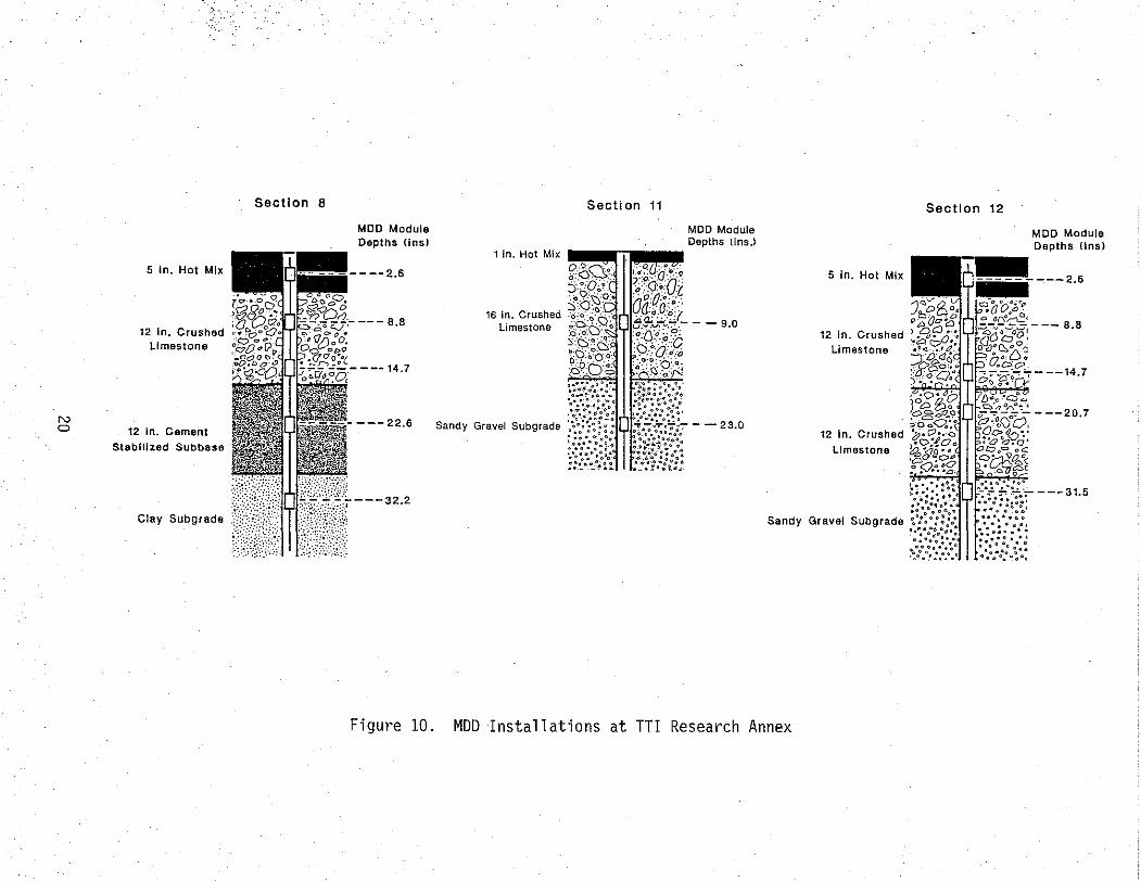
This section presents results of tests performed on the three instrumented
sections at the TTl Research Annex. The layer thicknesses and MDD locations are
shown in Figure 10. Sections 8 and 12 have similar layer thicknesses except that
Section 8 has a cement stabilized subbase over a clay subgrade, whereas Section
12 has a crushed limestone subbase over a sandy gravel subgrade. Five MDD
modules using the E300 series LVDT (0.30 inch full range) were installed in both
Sections 8 and 12. The anchors for Sections 8 and 12 were located at 70 inches
below the surface. Section 11 has a thin surfacing over a thick crushed lime
stone base over a sandy gravel subgrade; the anchor was located at 60 inches.
In Section 11, two MDD modules were installed using the ElOO series LVDT (0.10
inch full range).
In the remainder of this section, typical results and analyses performed
will be presented. This is broken down as follows:
4.1 Typical Results Under FWD Loading
4.2 Typical Results Under Truck Loading
4.3 Moduli Backcalculation
4.1 TYPICAL RESULTS UNDER FWD LOADING
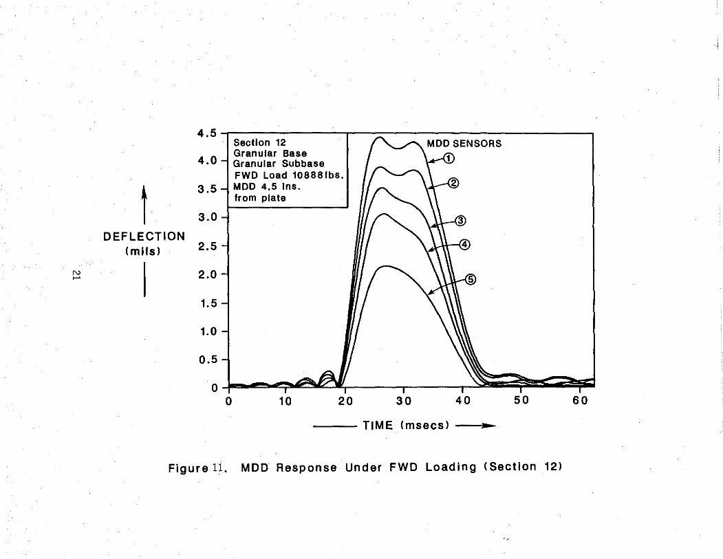
Typical MDD results from FWD loadings are shown in Figures 11 and 12.
Figure 11 is data collected on Section 12 (granular base and subbase). It is
noted that the maximum deflection was measured at approximately 4.4 mils and the
deflection decreased with depth in the pavement. Figure 12 shows the data from
Section 8 (cement stabilized subbase). Under similar FWD loading, the measured
maximum deflection was 2.5 mils. The deflections in sensors 3 (bottom of base),
4 (center of CTB) and 5 (top of subgrade) were essentially the same, at approxi
mately 1.2 mils. This demonstrates the rigid layer's ability to spread the load
and minimize damage to the underlying layers.
19
N o
Section 8
5 In. Hot Mix
12 In. Crushed :.';"o;;;-~i:trf;;>·~~~,;(. Limestone
12 In. Cement
Stabilized Subbase
Clay Subgrade
MOD Module Depths (ins)
- --2.6
---B.B
---14.7
---22.6
---32.2
Fi gure 10.
Section 11
1 in. Hot Mix
5 In. Hot Mix
Section 12
MOD Module Depths IIns)
y~~~---2.6
16 in. Crushed Limestone
12 in. Crushed .• 2,'':'',0.:1
Sandy Gravel Subgrade
Limestone
12 In. Crushed
Limestone
Sandy Gravel Subgrade
MOO Installations at TTI Research Annex
- --14.7
- --20.7
---31.5
N ......
t DEFLECTION
(mils)
4.5,-------------,---~-----------------------, Section 12
4.0
3.5
3.0
2.5
2.0
1.5
1.0
0.5
o
Granular Base Granuler Subbase FWD Load 108881bs. MOD 4.5 Ins. from plate
10 20 30 40
--- TIME (msecs) ..
50 60
Figure 11. MDD Response Under FWD Loading (Section 12)

2.6
2.4
2.2
2.0
t 1.8
1.6
DEFLECTION 1.4 (mils) 1.2
N N 1.0
0.8
0.6
0.4
0.2
0 0 10 20 30 40
Section 8 Granular Base Cement Stab. Subbase FWD Load 11072 Ibs. MOD 4.5 ins.
from plate
50 60
-- TIME (msecs) ...
Figure 12. MOD Response Under FWD Loading

STRAIN WITHIN lAYER
The MDD measures the relative displacement between the layer and the anchor.
However, the difference in MDD readings between two sensors is an indication of
the strain level that is being induced in the layer. In Section 12, MDD sensors
2, 3 and 4 are in the crushed limestone base layer. Figure 11 shows that the
difference between the peak deflection reading for sensors 2 and 4 is
approximately 0.80 mils. With the sensors being 11.9 inches apart, this corre
sponds to a strain level of 67 micros train.
The Falling Weight Deflectometer was used to test Sections 8, 11 and 12 at
different load levels. The strains measured in the granular layer are shown in
Figure 13. The strains in the thick pavement (Sections 8 and 12) were
essentially linear with load. However, the thin pavement response was
curvilinear, showing the typical stress hardening response that is observed in
laboratory tests on granular materials.
REPEATABILITY MEASUREMENTS
Multiple drops of the Falling Weight Deflectometer were made on Section 11.
The distance from the MDD hole and the edge of the FWD plate was fixed at two
inches. At two FWD load levels (8500 Ibs. and 16,000 1bs.), twelve drops were
monitored. The surface and depth deflections are shown in Tables 1 and 2. The
coefficient of variation was in most cases less than 1%. The Multi-Depth LVDT
sensors have a similar variation as the FWD geophones at similar displacements.
For example from Table 1, R3 of the FWD was recording a mean deflection of 3.07
mils and a coefficient of variance of 0.63% while D1 of the MDD was recording
4.30 miles with a coefficient of variance of 0.69%.
4.2 TYPICAL RESULTS UNDER TRUCK LOADING
The MDD was primarily designed to measure pavement response under wheel
loadings. The National Institute for Transport and Road Research in South
Africa has performed extensive studies in their Heavy Vehicle Simulator test
program (4). The MDD testing at the Texas Transportation Institute has focused
on pavement response under FWD loading; only a limited number of tests have been
carried out under truck loadings. An example of a typical MDD response under a
23

400
350
300
'Section 11 250 (MDD1-MDD2)
t 200 Strain
J-LE 150 Section 8
(MDD2-MDD3)
100
"-Section 12 50 (MDD2-MDD4)
O~ __ ~ ____ ~ ____ L-__ ~ ____ -L __ ___
344 480 620 760 895 1030 (50) (70) (90) (110) (130) (150)
FWD Loading Pressure ... kPa (psI)
Figure 13. Vertical compressive strains measured in granular bases for different FWD loads
24

Load DROP (l bs)
1 8,463 2 8,663 3 8,551 4 8,551 5 8,599 6 8,534
7 8,447 8 8,511 9 8,519
10 8,487 11 8,607 12 8,415 13 8,487
Mean: 8,527 Std.Dev: 67
Var.Coeff{%)0.78
Table 1. Repeatibility Measurements (FWD v MDD) on Section 11 at 8500 lb. Load Level
Measured Deflection (mils) Rl R2 R3 R4 R5 R6
15.65 6.66 3.04 2.12 1.71 1.46 15.65 6.79 3.08 2.16 1.67 1.49 15.81 6.70 3.08 2.12 1.67 1.46 15.61 6.74 3.08 2.12 1.67 1.49
15.77 6.70 3.08 2.12 1.67 1.42 15.61 6.79 3.08 2.12 1.67 1.49 15.53 6.70 3.08 2.12 1.67 1.46 15.53 6.74 3.08 2.12 1. 71 1.46 15.53 6.70 3.04 2.08 1.63 1.38 15.49 6.70 3.04 2.12 1. 71 1.49 15.49 6.79 3.08 2.12 1.67 1.42 15.32 6.66 3.04 2.12 1.63 1.38 15.53 6.74 3.08 2.12 1.67 1.49
+0-.
15.58 6.72 3.07 2.12 1.67 1.45 0.13 0.05 0.02 0.02 0.03 0.04 0.82 0.68 0.63 0.77 1.53 2.80
25
Multi-Depth Deflectometer
(mil s) R7 Dl D2
1.21 8.48 4.56 1.25 8.72 4.80 1. 21 8.60 4.62
1. 21 8.60 4.74
1.17 8.68 4.88 1.25 8.60 4.82
1.17 8.58 4.80
1. 21 8.60 4.68 1.13 8.62 4.68 1. 21 8.60 4.84
1.17 8.68 4.76 1.17 8.52 4.76
1. 21 8.62 4.80
1.20 8.60 4.74 0.03 0.06 0.08 2.85 0.69 1.68

Load DROP (l bs)
1 16,135 2 16,103 3 16,255
4 16,127 5 16,247 6 16,159
7 16,143 8 16,127
9 16,103 10 16,071
11 16,079 12 15,903 13 16,007 14 16,007
Mean: 16,105 Std.Dev: 89
Var.Coeff{%) 0.55
Table 2. Repeatibility Measurements (FWD v MOD) on Section 11 at 16,000 lb. Load Level.
Multi-Depth Deflectometer
Measured Deflection (mils) (mil s) Rl R2 R3 R4 R5 R6 R7 01 02
25.68 12.27 5.85 3.87 3.05 2.56 2.13 13.92 8.06 25.59 12.27 5.85 3.91 3.05 2.56 2.09 13.90 8.06 25.80 12.32 5.85 3.95 3.05 2.60 2.13 13.94 8.04 25.68 12.23 5.85 3.91 3.05 2.60 2.13 13.96 8.00 25.76 12.40 5.88 3.95 3.05 2.60 2.09 14.02 7.98 25.63 12.27 5.85 3.91 3.09 2.60 2.13 13.92 7.90 25.76 12.27 5.85 3.91 3.05 2.60 2.13 14.16 8.04 25.72 12.27 5.81 3.91 3.05 2.60 2.13 14.00 8.02 25.55 12.19 5.85 3.87 3.05 2.60 2.13 13.94 8.04 25.68 12.15 5.81 3.87 3.05 2.60 2.13 13.94 8.02 25.47 12.19 5.81 3.87 3.13 2.64 2.21 13.86 8.06 25.39 12.06 5.77 3.83 3.09 2.601 2.13 13.86 8.06 25.59 12.15 5.85 3.87 3.09 2.60 2.17 13.86 8.06 25.43 12.11 5.81 3.87 3.01 2.64 2.17 13.84 7.94
25.62 12.22 5.83 3.89 3.06 2.60 2.14 13.94 8.02 0.13 0.09 0.03 0.03 0.03 0.02 0.03 0.06 0.04 0.50 0.73 0.49 0.88 0.95 0.85 1.44 0.43 0.50
26
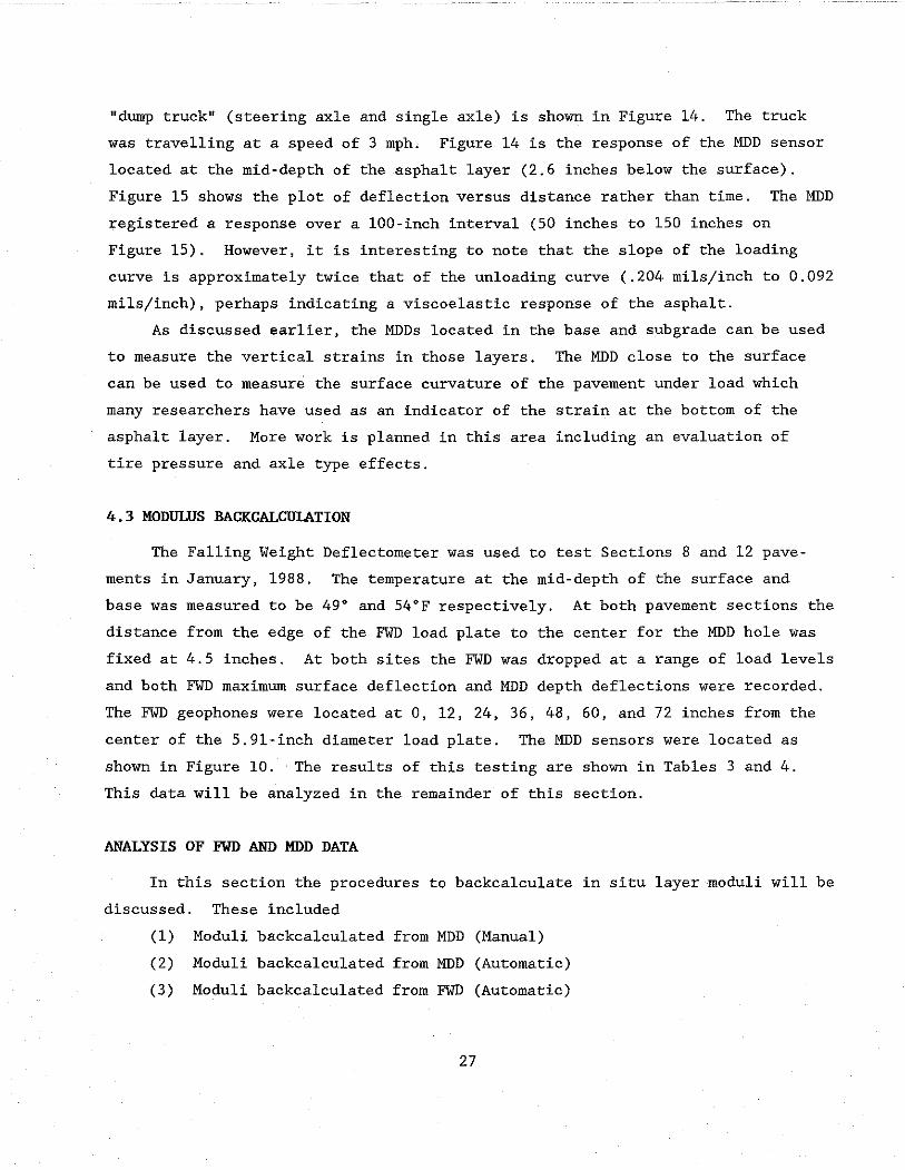
"dump truck" (steering axle and single axle) is shown in Figure 14. The truck
was travelling at a speed of 3 mph. Figure 14 is the response of the MDD sensor
located at the mid-depth of the asphalt layer (2.6 inches below the surface).
Figure 15 shows the plot of deflection versus distance rather than time. The MDD
registered a response over a 100-inch interval (50 inches to 150 inches on
Figure 15). However, it is interesting to note that the slope of the loading
curve is approximately twice that of the unloading curve (.204 mils/inch to 0.092
mils/inch), perhaps indicating a viscoelastic response of the asphalt.
As discussed earlier, the MDDs located in the base and sub grade can be used
to measure the vertical strains in those layers. The MDD close to the surface
can be used to measure the surface curvature of the pavement under load which
many researchers have used as an indicator of the strain at the bottom of the
asphalt layer. More work is planned in this area including an evaluation of
tire pressure and axle type effects.
4.3 MODULUS BAGKGALCULATION
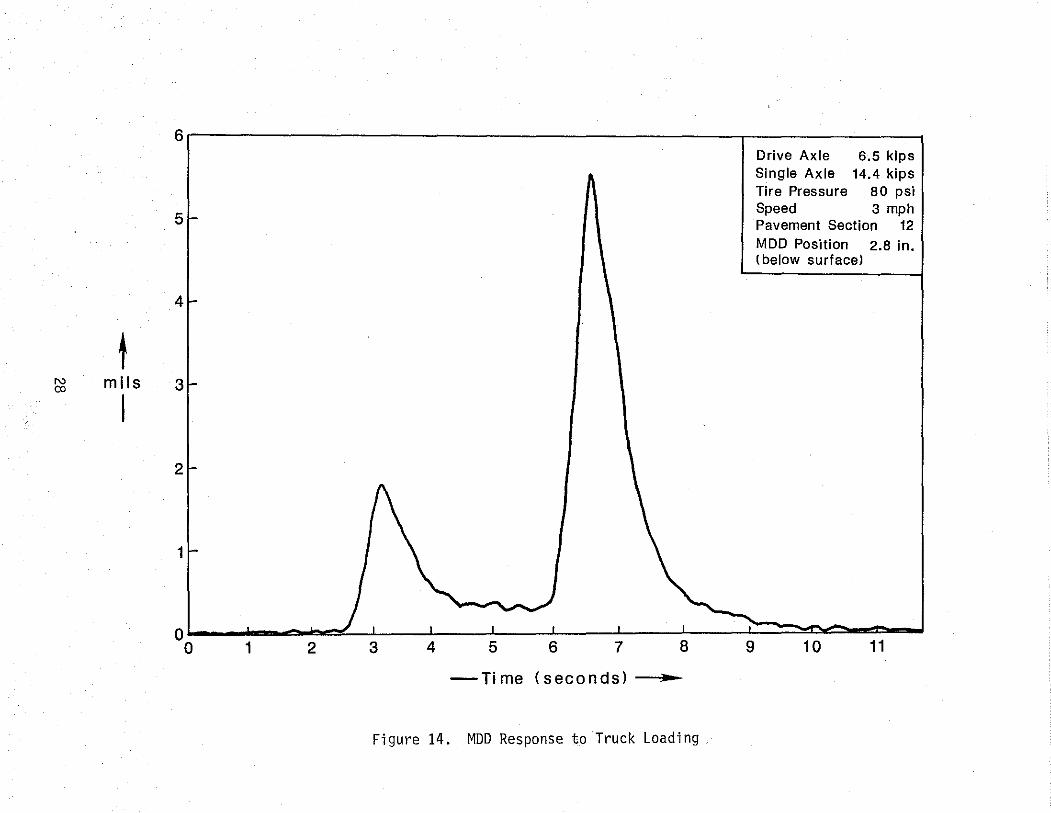
The Falling Weight Deflectometer was used to test Sections 8 and 12 pave
ments in January, 1988. The temperature at the mid-depth of the surface and
base was measured to be 49° and 54°F respectively. At both pavement sections the
distance from the edge of the FWD load plate to the center for the MDD hole was
fixed at 4.5 inches. At both sites the FWD was dropped at a range of load levels
and both FWD maximum surface deflection and MDD depth deflections were recorded.
The FWD geophones were located at 0, 12, 24, 36, 48, 60, and 72 inches from the
center of the 5.91-inch diameter load plate. The MDD sensors were located as
shown in Figure 10. The results of this testing are shown in Tables 3 and 4.
This data will be analyzed in the remainder of this section.
ANALYSIS OF FWD AND MDD DATA
In this section the procedures to backcalcu1ate in situ layer moduli will be
discussed. These included
(1) Moduli backca1culated from MDD (Manual)
(2) Moduli backcalcu1ated from MDD (Automatic)
(3) Moduli backca1culated from FWD (Automatic)
27
6 Drive Axle 6.5 kips Single Axle 14.4 kips Tire Pressure 80 psi
5 Speed 3 mph Pavement Section 12 MDD Position 2.8 in. (below surfacel
4
t N mils 3 co
I 2
-Time (seconds) ..
Figure 14. MDD Response to Truck Loading

.,
N <0
6r---------------------------------------.-------------~
5
4
Single Axle Speed Tire Pressure
14.4 kips 3 mph 80 psi
12
2.8 in. Pavement Section MOO Position (below surface)
t 3
mils
I 2
1
o~~~--------------------~~~~~
-1L-____ ~ ____ _L ____ ~ ______ L_ ____ ~ ____ -L ____ ~ ______ L_ ____ ~ __ ~
o 25 50 75 100 125 150 175 200 225
--Distance (in.) ..
Figure 15. MOD Deflection Bowl Under Truck Loading

Table 3. FWD and MDD Maximum Deflection data for Section H at TTl Research Annex
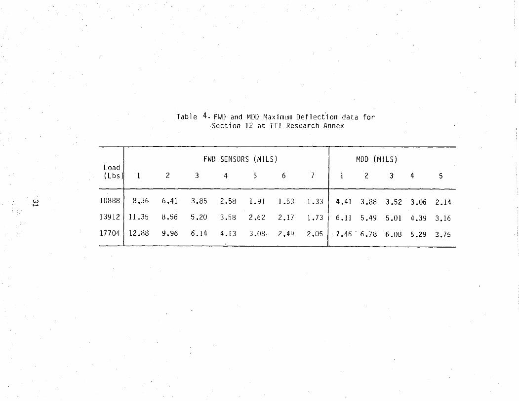
Table 4. FW[) and Mllll Maximulil Deflecfion data for Section 12 at TTl Research Annex
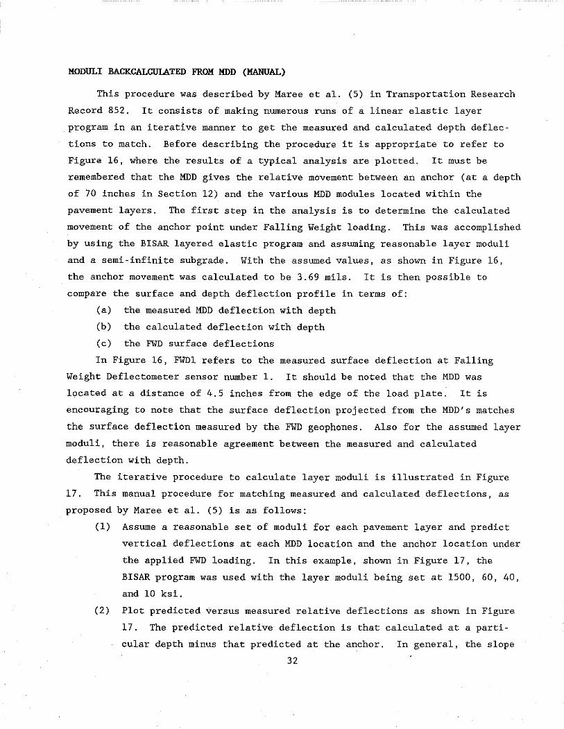
MODULI BACKCALCUlATED FROM MDD (MANUAL)
This procedure was described by Maree et al. (5) in Transportation Research
Record 852. It consists of making numerous runs of a linear elastic layer
program in an iterative manner to get the measured and calculated depth deflec
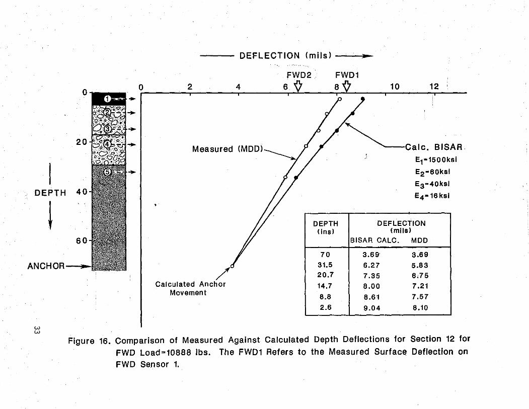
tions to match. Before describing the procedure it is appropriate to refer to
Figure 16, where the results of a typical analysis are plotted. It must be
remembered that the MDD gives the relative movement between an anchor (at a depth
of 70 inches in Section 12) and the various MDD modules located within the
pavement layers. The first step in the analysis is to determine the calculated
movement of the anchor point under Falling Weight loading. This was accomplished
by using the BISAR layered elastic program and assuming reasonable layer moduli
and a semi-infinite subgrade. With the assumed values, as shown in Figure 16,
the anchor movement was calculated to be 3.69 mils. It is then possible to
compare the surface and depth deflection profile in terms of:
(a) the measured MDD deflection with depth
(b) the calculated deflection with depth
(c) the FWD surface deflections
In Figure 16, FWDI refers to the measured surface deflection at Falling
Weight Deflectometer sensor number 1. It should be noted that the MDD was
located at a distance of 4.5 inches from the edge of the load plate. It is
encouraging to note that the surface deflection projected from the MDD's matches
the surface deflection measured by the FWD geophones. Also for the assumed layer
moduli, there is reasonable agreement between the measured and calculated
deflection with depth.
The iterative procedure to calculate layer moduli is illustrated in Figure
17. This manual procedure for matching measured and calculated deflections, as
proposed by Maree et al. (5) is as follows:
(1) Assume a reasonable set of moduli for each pavement layer and predict
vertical deflections at each MDD location and the anchor location under
the applied FWD loading. In this example, shown in Figure 17, the
BISAR program was used with the layer moduli being set at 1500, 60, 40,
and 10 ksi.
(2) Plot predicted versus measured relative deflections as shown in Figure
17. The predicted relative deflection is that calculated at a parti
cular depth minus that predicted at the anchor. In general, the slope
32
o o 2
20.~~
--- DEFLECTION (mils) ..
4
Measured (MDD)
FWD2 6
FWD1 10
~caIC.
12
BISAR·
DEPTH 40
E1-1500ksi
E2-60ksl
E3-40ksl
E4 -16ksl ,
DEPTH DEFLECTION ( Ins) (mils)
60 BISAR CALC. MDD
70 3.69 3.69
ANCHOR-_ /
31.5 6.27 5.83
w w
20.7 7.35 6.75 Calculated Anchor 14.7 8.00 7.21
Movement 8.8 8.61 7.57
2.6 9.04 8.10
Figure 16. Comparison of Measured Against Calculated Depth Deflections for Section 12 for
FWD Load=10888 Ibs. The FWD1 Refers to the Measured Surface Deflection on
FWD Sensor 1.

DEPTH
. W ./'>
MDD1
MDD2
MDD3
MDD4 20
MDD5
(ins,) 40
60
ANCHOR~.r
RELATIVE DEFLECTION (mils)
1 2 3 4 5 6 7
""-1'--(Ei=1500, 60, 40, 10)
Measured (Ei=1500, 60, 40, 16)
(Ej=1500, 85, 40, 16)
Section 12 FWD Load=10888 Ibs. MDD=4.5 in. from plate
Figure 17. Manual Iterative Procedure for Matching Measured vs. Calculated Relative Depth Deflections
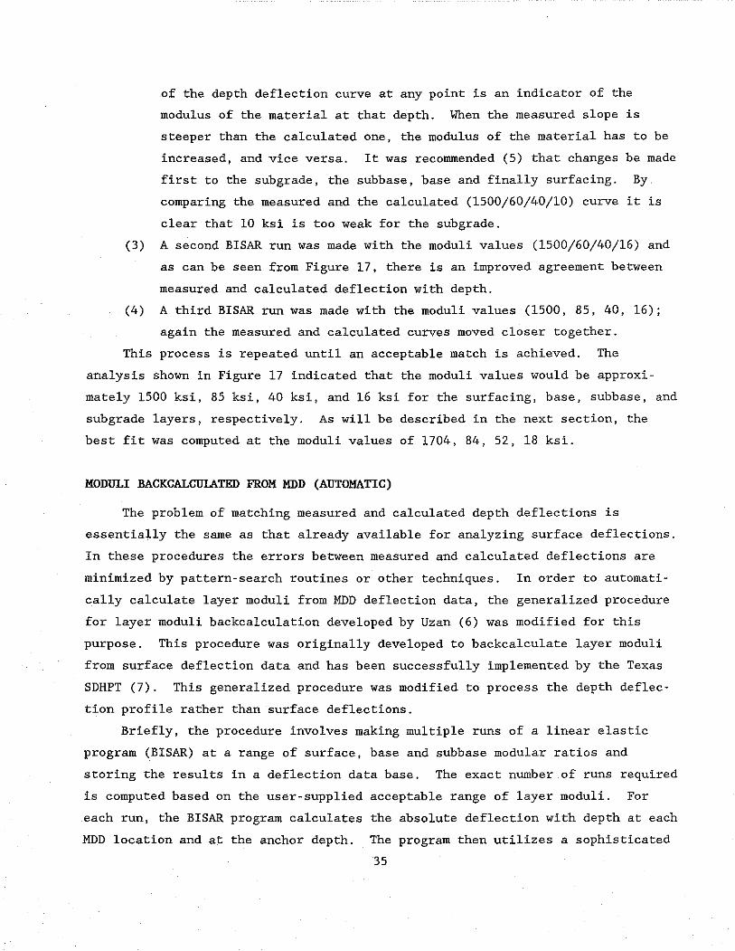
of the depth deflection curve at any point is an indicator of the
modulus of the material at that depth. When the measured slope is
steeper than the calculated one, the modulus of the material has to be
increased, and vice versa. It was recommended (5) that changes be made
first to the subgrade, the subbase, base and finally surfacing. By
comparing the measured and the calculated (1500/60/40/10) curve it is
clear that 10 ksi is too weak for the subgrade.
(3) A second BISAR run was made with the moduli values (1500/60/40/16) and
as can be seen from Figure 17, there is an improved agreement between
measured and calculated deflection with depth.
(4) A third BISAR run was made with the moduli values (1500, 85, 40, 16);
again the measured and calculated curves moved closer together.
This process is repeated until an acceptable match is achieved. The
analysis shown in Figure 17 indicated that the moduli values would be approxi
mately 1500 ksi, 85 ksi, 40 ksi, and 16 ksi for the surfacing, base, subbase, and
subgrade layers, respectively. As will be described in the next section, the
best fit was computed at the moduli values of 1704, 84, 52, 18 ksi.
MODULI BACKCALCUIATED FROM MDD (AUTOMATIC)
The problem of matching measured and calculated depth deflections is
essentially the same as that already available for analyzing surface deflections.
In these procedures the errors between measured and calculated deflections are
minimized by pattern-search routines or other techniques. In order to automati
cally calculate layer moduli from MDD deflection data, the generalized procedure
for layer moduli backcalculation developed by Uzan (6) was modified for this
purpose. This procedure was originally developed to backcalculate layer moduli
from surface deflection data and has been successfully implemented by the Texas
SDHPT (7). This generalized procedure was modified to process the depth deflec
tion profile rather than surface deflections.
Briefly, the procedure involves making multiple runs of a linear elastic
program (BISAR) at a range of surface, base and subbase modular ratios and
storing the results in a deflection data base. The exact number of runs required
is computed based on the user-supplied acceptable range of layer moduli. For
each run, the BISAR program calculates the absolute deflection with depth at each
MDD location and at the anchor depth. The program then utilizes a sophisticated
35

pattern search technique to minimize the error between the calculated and
measured relative deflection. This system has been implemented on a microcom
puter. A typical input screen is shown in Figure 18 and typical calculated
results are shown in Figure 19. To perform the necessary deflection data base
generation takes approximately 10 minutes on a 286-type microcomputer for a 3-
layer system and 20 minutes for a 4-layer system. Once complete, it takes only
about 30 seconds to find the best fit for each measured deflection bowl.
The automated procedure has the capability of specifying the depth to
bedrock which is known to be significant when matching surface deflections.
Tables Sa and 5b show the set of moduli values which minimizes the error between
the measured and calculated depth deflections for Section 8. Table Sa assumed a
semi-infinite sub grade layer, whereas in Table 5b, a rock layer was assumed to be
250 inches below the surface. The total error is the accumulative absolute
percentage error between measured and calculated depth deflections. Tables 6a
and 6b show the results obtained from Section 12, modeled as a 4-layer system
with a l2-inch granular base and l2-inch granular subbase. Tables 7a and 7b show
the results from Section 12 modeled as a 3-layer system with a 24-inch granular
base course. The following conclusions can be drawn from these tables:
(1) For this particular analysis, the depth to bedrock does not appear
significant when processing MDD data. Similar moduli values were
obtained, particularly on Section 12.
(2) The fit on Section 8 was relatively poor. This is the section with a
stiff cement-stabilized subbase. On Section 12 the total error was
small, as low as 3.1%, or 0.6% per sensor reading.
(3) Using a 3-layer or 4-layer system to model Section 12 had no effect on
the sub grade moduli values.
MODULI BACKCALCULATED FROM FWD (AUTOMATIC)
The surface deflection data collected on Sections 8 and 12 was shown in
Tables 3 and 4. There are several procedures available to automatically process
surface deflection data to generate layer moduli values (7, 8, 9). In this
analysis the procedure developed by Uzan (7) was used. This procedure uses a
linear-elastic program (BISAR) to generate a deflection data base to cover the
range of layer moduli as supplied by the user. Once generated, a pattern search
routine is used to minimize error between measured and calculated bowls.
36

5 10 15 20 25 30 35 40 45 50 55 60 65 70 75 80 . . . .. . . . . . . . . . . . . . " ............................................................................. . 1 2 TITLE xxxxxxxxxxxxxxxxxxxxxxxxxxxxxxxxxxxxxxxxxxxxxxxxxxxxxxxxxxxx 3 H1 H2 H3 H4 4 xxxxxx xxxxxx xxxxxx xxxxxx 5 RADIUS OF PLATE NUMBER OF LVDTS 6 xxxxxxxxxx X 7 DEPTH OF LVDT'S AND WEIGHTING FACTORS 8 LVDT No. 9 1 2 3 4 5
10 DEPTH OF LVDT 6 7
RADIAL DIST ANCE FROM PLATE EDGE
11 xxxxxxx xxxxxxx xxxxxxx xxxxxxx xxxxxxx xxxxxxx xxxxxxx 12 WEIGHTING FACTORS OF LVDT'S xxxxxxxx 13 xxxxxxx xxxxxxx xxxxxxx xxxxxxx xxxxxxx xxxxxxx XXXXXXX 14 15 16 17 18 19 20 21 22 23 24
SUBGRADE MODULUS (MOST PROBABLE VALUE IN KSI) AND POISSON'S RATIO XXXXXXXXX XXXXX
MODULUS OF THIRD LAYER (IN KSI) MINIMUM MAXIMUM AND POISSON'S RATIO
XXXXXXXXX XXXXXXXXX XXXXX MODULUS OF SECOND LAYER (IN KSI)
MINIMUM MAXIMUM AND POISSON'S RATIO XXXXXXXXX XXXXXXXXX XXXXX
MODULUS OF FIRST LAYER (IN KSI) MINIMUM MAXIMUM AND POISSON'S RATIO
XXXXXXXXX XXXXXXXXX XXXXX . . .. . . . . . . . . . . .. . . .................................................................................... 5 10 15 20 25 30 35 40 45 50 55 60 65 70 75 80
1 2 3 4 5 6 7 8 9
10 11 12 13 14 15 16 17 18 19 20 21 22 23
Figure 18. Input screen to MDD AnalYSis Program. The User fills in the X's. This information is used to supply input to 3ISAR to calculate the deflection data base.
37

*********************************** MULTI-DEPTH DEFLECTOMETER ANALYSIS ***********************************
section 12 three layer
DISTANCE TO EDGE OF PLATE RADIUS OF LOAD PLATE (IN.):
SURFACE THICKNESS (IN. ): BASE THICKNESS (IN.) : SUBGRADE THICKNESS (IN.):
4.500 (IN.) 5.910
5.000 24.000
221.000 DEPTH TO SENSORS WEIGHTING FACTORS
01 = 2.60 1.0 02 = 8.00 1.0 03 = 14.70 1.0 04 = 20.70 1.0 05 = 31.50 1.0
STATION: 2 2 01 02 03 04 D5 MEASURED DEFLECTI'bN: 4.41 3.88 3.52 3.06 2.14 CALCULATED DEFLECTION: 4.46 4.10 3.42 2.94 2.13
% ERROR ·1.11 ·5.73 2.70 4.03 .69
LAYER: SURFACE BASE SUBGRADE MODULI VALUES .(PSI): 1980557. 59417. 19806. AT OR NEAR LIMITS? YES
INITIAL MODULI VALUES MINIMUM MAXIMUM 100000. 2000000. 30000. 150000.
20000. DEPTH TO ANCHOR
70.0 INS.
PLATE LOAD (LBS) : PLATE PRESSURE (PSI):
ABS SUM OF % ERROR:
ERROR SQUARED:
10887 99.23
• 143E+02
.581E·02
NOTE: LOCAL MINIMUM ENCOUNTERED CHECK RESULTS CAREFULLY
Figure 19. Output report from the MDD Analysis Program
38

Table 5a. Moduli Calculated Automatically from MDD Section 8 Semi-Infinite Subgrade Vi = .35, .35, .25, .45
FWD Load MODULI (KSI) (1 bs) MDD DEFLECTIONS (MILS) E1 E2 E3 E4
Measured 2.48 1.68 1.25 1.16 1.14 11072 2000 78 2373 12
Calculated 2.22 1.84 1.32 1.17 1.06
Measured 3.03 2.02 1.29 1.24 1.12 14464 2000 70 2708 23
Calculated 2.73 2.17 1.40 1.18 1.08
Measured 3.21 2.07 1.07 1.15 1.06 18352 2000 84 5000 31
Calculated 2.75 2.15 1.31 1.07 .96
Table 5b. Moduli Calculated Automatically from MDD Section 8 - Bedrock at 250 inches below surface
FWD Load MODULI (KSI) (1 bs) MDD DEFLECTIONS (MILS) E1 E2 E3 E4
Measured 2.48 1.68 1.25 1.16 1.14 11072 2000 77 1893 16
Calculated 2.23 1.85 1.32 1.17 1.03
Measured 3.03 2.02 1.29 1.24 1.12 14464 2000 70 2803 23
Calculated 2.72 2.17 1.41 1.19 1.06
Measured 3.21 2.07 1.07 1.15 1.06 18352 2000 84 4898 33
Calculated 2.77 2.16 1.30 1.05 0.94
* The total error is the accumulative absolute percentage error between measured and calculated depth deflections.
39
TOTAL* ERROR
%
35.2
36.9
60.0
TOTAL* ERROR
%
36.0
36.7
60.1

Table 6a. Moduli Calculated Automatically from MDD Section 12 - 4-Layer System Semi-Infinite Subgrade Vi = .35, .35, .35, .45
FWD TOTAL* Load MODULI (KSI) ERROR (lbs) MDD DEFLECTIONS (MILS) E1 E2 E3 E, %
Measured· 4.41 3.88 3.52 3.06 2.14 10888 1746 84 51 18 6.7
Calculated 4.33 3.99 3.52 3.02 2.15
Measured 6.11 5.49 5.01 4.39 3.16 13912 2000 83 48 14 4.8
Calculated 6.03 5.60 5.00 4.35 3.17
Measured 7.46 6.78 6.09 5.29 3.75 17704 1850 84 47 16 3.1
Calculated 7.40 6.85 6.09 5.25 3.76
Table 6b. Moduli Calculated Automatically from MDD Section 12 - 4-Layer System - Bedrock at 250 inches below Surface
FWD TOTAL* Load MODULI (KSI) ERROR (1 bs) MDD DEFLECTIONS (MILS) E1 E2 E3 E, %
Measured 4.41 3.88 3.52 3.06 2.14 10888 1705 84 52 18 6.8
Calculated 4.33 3.99 3.51 3.02 2.15
Measured 6.11 5.49 5.01 4.39 3.16 13912 2000 83 48 14 4.8
Calculated 6.02 5.60 5.00 4.35 3.17
Measured 7.46 6.78 6.09 5.29 3.75 17704 1535 88 49 16 3.3
Calculated 7.40 6.86 6.09 5.25 3.76
* The total error is the accumulative absolute percentage error between measured and calculated depth deflections.
40
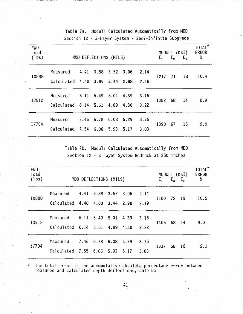
Table 7a. Moduli Calculated Automatically from MDD Section 12 - 3-Layer System - Semi-Infinite Subgrade
FWD TOTAL* Load MODULI (KSI) ERROR (1 bs) MDD DEFLECTIONS (MILS) E, E2 E3 %
Measured 4.41 3.88 3.52 3.06 2.14 10888 1217 71 18 10.4
Calculated 4.40 3.99 3.44 2.98 2.18
Measured 6.11 5.49 5.01 4.39 3.16 13912 1382 68 14 8.9
Calculated 6.14 5.61 4.89 4.30 3.22
Measured 7.46 6.78 6.08 5.29 3.75 17704 1390 67 16 9.0
Calculated 7.54 6.86 5.93 5.17 3.83
Table 7b. Moduli Calculated Automatically from MDD Section 12 - 3-Layer System Bedrock at 250 inches
FWD TOTAL* Load MODULI (KSI) ERROR (1 bs) MDD DEFLECTIONS (MILS) E, E2 E3 %
Measured 4.41 3.88 3.52 3.06 2.14 10888 1100 72 19 10.5
Calculated 4.40 4.00 3.44 2.98 2.19
Measured 6.11 5.49 5.01 4.39 3.16 13912 1405 68 14 9.0
Calculated 6.14 5.61 4.89 4.30 3.22
Measured 7.46 6.78 6.08 5.29 3.75 17704 1337 68 16 9.1
Calculated 7.55 6.86 5.93 5.17 3.83
* The total error is the accumulative absolute percentage error between measured and calculated depth deflections,Table 5a
41

Runs were made with finite and infinite depth to bedrock. The results of this
analysis are shown in Tables 8 and 9. The surface and depth deflections were
measured simultaneously under the FWD load. The layer moduli values calculated
using the FWD load and surface deflections are compared with those calculated
using the FWD load and MDD depth deflections. In tables 8 and 9 the
backcalculated layer moduli values are given together with their respective lack
of fit error. This error indicates how the theoretically calculated deflection
bowl matches the measured bowl.
DISCUSSION OF RESULTS
Section 8 has a 12-inch cement-stabilized subbase; this layer is very stiff,
approaching the stiffness of lean concrete. The MDD data collected on this
section showed that the sensors 3, 4 and 5 produced similar deflections. At the
18,352 lb. load level the deflection at sensor 4 was higher than that recorded at
sensor 5, and other instances were observed where the deflections beneath the
stabilized layer were higher than those measured in that layer. This inverted
depth deflection profile is impossible to fit using linear-elastic theory, and
the errors shown in Table 8 are relatively large (>35%). For this analysis the
MDD backcalculated moduli values are not affected by varying the depth to
bedrock. However, they do not match those moduli backcalculated using the
surface deflection analysis.
The backcalculated moduli results from Section 12 are shown in Table 9.
This is a common pavement type found on many high volume pavements in Texas. It
has an asphalt surface (5-inch) over a thick granular layer (24-inch) on a
natural subgrade. For this section the moduli calculated from the MDD data only,
were not affected by depth to bedrock. However, the moduli obtained from the
surface deflections were significantly altered. There is a reasonable match of
layer moduli when the finite depth to bedrock (250 inches) is used. The base
layer moduli predicted from analysis of the FWD data compare very closely to
those calculated from the MDD; the maximum difference is 4 ksi, or 5%. It is
worth recalling that the Corps of Engineers recommended placing a rigid layer at
20 feet when backcalculating layer moduli using linear-elastic theory (8). The
results obtained on Section 12 appear to support that assumption.
42

Table 8. Comparing FWD and MDD Layer Moduli (ksi) for Section 8 (4-Layer System).
FWD FWD SURFACE DEPTH DEFLECTION MODULI3 LOAD DEFLECTION MODULI2 (1 bs) SUBGRADP E1 E2 E3 E4 Error4 E1 E2 E3 E4 Error4
% %
11072 Semi-Inf 2000 58 1305 28 12.1 2000 78 2373 12 35.2 Finite 2000 50 3771 13 9.7 2000 77 1893 16 36.0
14464 Semi-Inf 1119 71 500 27 13.2 2000 70 2708 23 36.9
Finite 1141 61 1670 14 5.9 2000 70 2803 23 36.7
18352 Semi-Inf 1383 80 500 30 10.8 2000 84 5000 31 60.0 Finite 1498 63 2066 15 4.0 2000 84 4898 33 61.0
1 SEMI-INF used in modeling subgrade. FINITE assumes a depth to bedrock of 250 inches.
2 Calculated using the Uzan procedure (7) with the bowls given in Tables 3 and 4.
3 From Tables Sa) and 5b). 4 Total absolute accumulative error between measured and calculated
deflections. Seven sensors for the FWD and five for the MDD.
43
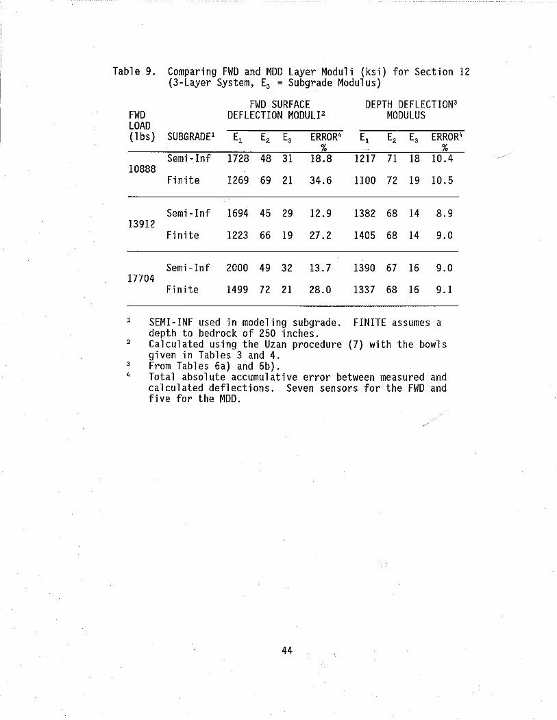
Table 9. Comparing FWD and MOD Layer Moduli (ksi) for Section 12 (3-Layer System, E3 = Subgrade Modulus)
FWD SURFACE DEPTH DEFLECTION3 FWD DEFLECTION MODULI2 MODULUS LOAD (1 bs) SUBGRADE' E, E2 E3 ERROR' E, E2 E3 ERROR'
% % Semi-Inf 1728 48 31 18.8 1217 71 18 10.4
10888 Finite 1269 69 21 34.6 HOD 72 19 10.5
Semi-Inf 1694 45 29 12.9 1382 68 14 8.9 13912
Finite 1223 66 19 27.2 1405 68 14 9.0
Semi-Inf 2000 49 32 13.7 1390 67 16 9.0 17704
Finite 1499 72 21 28.0 1337 68 16 9.1
1 SEMI-INF used in modeling subgrade. FINITE assumes a depth to bedrock of 250 inches.
2 Calculated using the Uzan procedure (7) with the bowls given in Tables 3 and 4.
3 From Tables 6a) and 6b). , Total absolute accumulative error between measured and calculated deflections. Seven sensors for the FWD and five for the MOD.
44

SECTION 5
CONCLUSION
This report has described the installation of Multi-Depth Deflectometers in
three pavement sections at the Texas A&M Research Annex. The conclusions of this
investigation are as follows:
'(I) The Multi-Depth Deflectometer shows considerable potential for assist
ing in many areas of pavement research; particularly accelerated
loading testing, tire pressure studies, rutting studies and modulus
backcalculation verification. The Multi-Depth Deflectometer has
numerous advantages over the conventional single depth deflectometer
system.
(2) The system is relatively inexpensive. The hardware for a typical
installation costs less than $2,000 and the MDD units can be recovered
after use. The final cost will depend on the type of LVDT chosen. In
long-term testing where the units are to be installed for several
months (or years), it is recommended that the hermetically sealed units
be used. On extracting the MOD units from Section 8, rust was observed
on the LVDT body. The hermetically-sealed LVDTs cost approximately
$230 (1988 prices), compared with $35 for the regular units.
(3) Stripping an existing hole and reinstalling the MDDs may sometimes be
required. In Section 12 it was observed that the center core could
become locked. This is caused when one of the modules moves slightly
causing the central core to "lock-up". This is easily detected and
reinstallation of the hole takes approximately one day.
(4) Results gathered to date show the MDD response is repeatable under a
range of Falling Weight Deflectometer loading.
(5) Efforts to match layer moduli backcalculated from both surface deflec
tions and depth deflections were successful on Section 12 (asphalt/
granular base/subgrade) but unsuccessful on Section 8 (cement stabi
lized subbase). The best fit occurred when a bedrock layer was
assumed at 250 inches below the surface.
Further work is underway to improve the system in three areas, these are:
45
(1) An experimental version of the MDD is being developed with an accelerometer (or geophone) mounted on the center core. This will permit measurement of the actual anchor movement, which can then be compared with the movement calculated using the MDD Analysis Program (Figure 19).
(2) The top cap is being redesigned so that the cables can be placed in a shallow saw cut. The connector cable will no longer be required. The MDD system will therefore be permanently installed flush with the surface. The FWD load plate can then be placed directly over the MDD hole.
(3) An evaluation is being made of using DC rather than AC LVDT's. The DC units are simpler to use and will make the system less expensive as the signal conditioner box will no longer be required. However, one concern is the durability of the DC compared with the AC units.
46
REFERENCES
1. American Association of State Highway and Transportation Officials Guide for Design of Pavement Structure, 1986, American Association of State Highway Transportation Officials, Washington, D.C.
2. Basson, J. E. B., Wijnberger, O. J., and Sku1tety, J., "A Multistage Sensor for the Measurement of Resilient Deflections and Permanent Deformation at Various Depths in Road Pavements," Council for Scientific and Industrial Reseach, Pretoria, South Africa, NITRR RP/3/81, Feb., 1981.
3. Loesch, M. D., Koedood, J., and Botha, D. F., "Field Installation of Mu1tiDepth Deflectors," Council for Scientific and Industrial Research,Pretoria, South Africa, National Institute for Transportation and Road Research TP/92/83, August, 1983.
4. Freeme, C. R., Servas, V. P., and Walker, R. N., "Pavement Behavior as Determined by HVS Testing," International Conference on Bearing Capacity of Roads and Airfields, 1986.
5. Maree, J. H., Van Zy1, N. J. W., and Freeme, C. R., "Effective Moduli and Stress Dependance of Pavement Materials as Measured in Some Heavy Vehicle Simulator Tests," Transportation Research Record, 852.
6. Uzan, J., Lytton, R. L., and Germann, F. P., "General Procedure for Backca1-cu1ating Layer Moduli," Paper at the First Symposium on Nondestructive Testing of Pavements and Backcalcu1ation of Moduli, June, 1988.
7. Uzan, J., Scullion, T., Michalek, C. H., Parades, M., and Lytton, R. L., "A Microcomputer Based Procedure for Backca1cu1ating Layer Moduli from FWD Data," Texas Transportation Institute Research Report 1123-1, July, 1988.
8. Bush, A. J., "Nondestructive Testing for Light Aircraft Pavements, Phase II. Development of the Nondestructive Methodology," Report No. FAA-RD-80-9-11, Federal Aviation Authority, Washington, D. C., November, 1980.
9. Lytton, R. L., Roberts, F. L., and Stoffels, S., "Determination of Asphaltic Concrete Pavement Structural Properties by Nondestructive Testing," National Cooperative Highway Research Program Study Report 10-27, Appendix G, April, 1986.
47