FIelD CoNNeCtIoNs AND CoNtRol WIRING FoR...
28
Issue Date: September 29, 2012 WIRING DIAGRAM CONTRACTOR _______________________ PURCHASER ____________________________________________ ORDER NO. __________________________ JOB NAME ______________________________________________ YORK CONTRACT NO. _________________ LOCATION ______________________________________________ YORK ORDER NO. ____________________ ENGINEER _____________________________________________ REFERENCE DATE ______ APPROVAL DATE _______ CONSTRUCTION DATE _______ Supersedes 201.30-PW2 (512) Form 201.30-PW2 (912) FIELD CONNECTIONS AND CONTROL WIRING FOR YVWA CHILLER JOB DATA: CHILLER (PIN 1-4) YVWA VSD FRAME SIZE (PIN 11) ______ RUNNING LOAD AMPS (RLA) ______ POWER SUPPLY VOLTAGE( PIN 20, 21) ______ AUTO TRANSFORMER ______ YES ______ NO CIRCUIT BREAKER (PIN 22) ______ YES ______ NO DISCONNECT SWITCH (PIN 22) ______ YES ______ NO
Transcript of FIelD CoNNeCtIoNs AND CoNtRol WIRING FoR...

Issue Date: September 29, 2012
WIRING DIAGRAMCONTRACTOR _______________________ PURCHASER ____________________________________________ORDER NO. __________________________ JOB NAME ______________________________________________YORK CONTRACT NO. _________________ LOCATION ______________________________________________YORK ORDER NO. ____________________ ENGINEER _____________________________________________
REFERENCE DATE ______ APPROVAL DATE _______ CONSTRUCTION DATE _______
Supersedes 201.30-PW2 (512) Form 201.30-PW2 (912)
FIelD CoNNeCtIoNs AND CoNtRol WIRING FoR YvWA ChIlleR
JoB DAtA:
CHILLER (PIN 1-4) YVWA
VSD FRAME SIzE (PIN 11) ______
RUNNING LOAD AMPS (RLA) ______
POWER SUPPLY VOLTAGE( PIN 20, 21) ______
AUTO TRANSFORMER ______ YES ______ NO
CIRCUIT BREAKER (PIN 22) ______ YES ______ NO
DISCONNECT SWITCH (PIN 22) ______ YES ______ NO

FORM 201.30-PW2 ISSUE DATE: 9/29/2012
JOHNSON CONTROLS2
This equipment is a relatively complicated apparatus. During installation, operation maintenance or service, individuals may be exposed to certain components or conditions including, but not limited to: refrigerants, materials under pressure, rotating components, and both high and low voltage. Each of these items has the potential, if misused or handled improperly, to cause bodily injury or death. It is the obligation and respon-sibility of operating/service personnel to identify and recognize these inherent hazards, protect themselves, and proceed safely in completing their tasks. Failure to comply with any of these requirements could result in serious damage to the equipment and the property in
IMPoRtANt!READ BEFORE PROCEEDING!
GeNeRAl sAFetY GuIDelINes
which it is situated, as well as severe personal injury or death to themselves and people at the site.
This document is intended for use by owner-authorized operating/service personnel. It is expected that these individuals possess independent training that will en-able them to perform their assigned tasks properly and safely. It is essential that, prior to performing any task on this equipment, this individual shall have read and understood this document and any referenced mate-rials. This individual shall also be familiar with and comply with all applicable governmental standards and regulations pertaining to the task in question.
sAFetY sYMBolsThe following symbols are used in this document to alert the reader to specific situations:
Indicates a possible hazardous situation which will result in death or serious injury if proper care is not taken.
Indicates a potentially hazardous situa-tion which will result in possible injuries or damage to equipment if proper care is not taken.
Identifies a hazard which could lead to damage to the machine, damage to other equipment and/or environmental pollu-tion if proper care is not taken or instruc-tions and are not followed.
Highlights additional information useful to the technician in completing the work being performed properly.
External wiring, unless specified as an optional connection in the manufacturer’s product line, is not to be connected inside the control cabinet. Devices such as relays, switches, transducers and controls and any external wiring must not be installed inside the micro panel. All wiring must be in accor-dance with Johnson Controls’ published specifications and must be performed only by a qualified electrician. Johnson Controls will NOT be responsible for damage/problems resulting from improper connections to the controls or application of improper control signals. Failure to follow this warn-ing will void the manufacturer’s warranty and cause serious damage to property or personal injury.

FORM 201.30-PW2 ISSUE DATE: 9/29/2012
JOHNSON CONTROLS 3
ChANGeABIlItY oF thIs DoCuMeNt
In complying with Johnson Controls’ policy for con-tinuous product improvement, the information con-tained in this document is subject to change without notice. Johnson Controls makes no commitment to update or provide current information automatically to the manual owner. Updated manuals, if applicable, can be obtained by contacting the nearest Johnson Controls Service office.
Operating/service personnel maintain responsibility for the applicability of these documents to the equipment. If there is any question regarding the applicability of
these documents, the technician should verify whether the equipment has been modified and if current litera-ture is available from the owner of the equipment prior to performing any work on the chiller.
ChANGe BARs
Revisions made to this document are indicated with a line along the left or right hand column in the area the revision was made. These revisions are to technical in-formation and any other changes in spelling, grammar or formatting are not included.
MANuAl DesCRIPtIoN PARt NuMBeR
E-Link Gateway Installation Instructions 24-104-04-9 Rev. C
AssoCIAteD lIteRAtuRe
evAP tuBes
CoND tuBes
NoMeNClAtuRe
YvWA
uNIt tYPe YORK Variable Speed Screw Water-Cooled Chiller Design Series
MB MB
APPlICAtIoNS=Std Water ChillerD=Dry Tower/RadiatorP=Process BrineT=Ice Thermal Storage
s
PIN 19X=No SelectionQ=Special Quote
X
2 CMPREE=136/136 mmFE=145/136 mmFF=145/145 mm
ee MoDel
A
PAssB=Evap: 2-pass; Cond: 1 passC=Evap: 3-pass; Cond: 1 passE=Evap: 2-pass; Cond: 2 passF=Evap: 3-pass; Cond: 2 pass
B
stARteRA=Frame AB=Frame BC=Frame CD=Frame D
ANoMINAl CAP TR = 200-300kW = 703- 1055
0200
vARIABle sPeeD DRIve NoMeNClAtuRe2CMPRtvP
vsD PANel
X
NuMBeR oFCoMPRessoRs
PoWeR INteRuPPtIoNX = Base ModelB = Circuit BreakerD = Disconnect Switch
CoolINGW = WaterG = Glycol
W
voltAGe17 = 200V 60Hz with autotransformer 28 = 230V 60Hz with autotransformer40 = 380V 60Hz50 = 400V 60Hz46 = 460V 60Hz58 = 575V 60Hz with autotransformer65 = 380V 50Hz68 = 415V 50Hz
FRAMe sIZeA BCD
17 A-

FORM 201.30-PW2 ISSUE DATE: 9/29/2012
JOHNSON CONTROLS4
leGeND Transient Voltage Suppression
Terminal Block for Customer Connections (1TB)
Terminal Block for YORK Connections
Wiring Components by YORK
Optional Equipment
Wiring and/or Components by Others
Note Well
A Component Marked Thus is External to the Control Panel
ES
EXT
*=NOT REQUIRED FOR ALL MODELS
NB
NotesNOTES FOR DRAWINGS
No. DesCRIPtIoN
1All field wiring shall be in accordance with the relevant electrical code as well as all other ap-plicable codes and specifications.
2 Contacts must be suitable for switching 115VAC at 5 MA.
3Contacts are rated at 115V/230V, 100VA, resis-tive load only, and must be suppressed at load by user.
4 See installation, operation and maintenance manual when optional equipment is used.
5 Not applicable6 Not applicable
7 Applied to models ending in 65B, 65C, 50B, 50C, 68B, 68C, and all models ending in D.
8
A. Fuses -F(4FU and 5FU) are 12 A for 380V, 400V and 415V models.
B. Fuses -F (4FU and 5FU) are 10 A for 200V, 230V, 460V and 575V models.
9
A. Fuses -F(1FU, 2FU and 3FU) are 630 A for models ending in A & B.
B. Fuses -F(1FU, 2FU and 3FU) are 800 A for models ending in C.
C. Fuses -F (1FU, 2FU and 3FU) are 900 A for models ending in 46D & 58D.
D. Fuses -F (1FU, 2FU and 3FU) are 1000 A for models ending in 40D, 65D, 50D & 68D.
10 See Detail B for units with auto transformer.11 Not applicable.12 For Detail E for CE units.
13 Options not applicable to all units, remote temp reset, remote current limit.
15
A. For models ending in A or B - AGDB P/N is 031-02061-003.
B. For models ending in C OR D - AGDB P/N is 031-02061-001.
16 Accessory E-Link Gateway consisting of AMGB (cannot be used with RCC accessory)
17 Not applicable.18 Not applicable.
19
A. Models ending in A get capacitors C1, C5, C2 and C6.
B. Models ending in B and C get capacitors C1, C3, C5, C2, C4 and C6.
C. Models ending in D get capacitors C1, C3, C5, C7, C2, C4, C6 and C8.
20 See Detail C for optional circuit breaker or discon-nect switch.
For information on the notes in the following wiring diagrams not listed here, refer to the notes legend on the language kit that ships with the unit, which is located on the inside of the panel door.
FORM 201.30-PW2 ISSUE DATE: 9/29/2012
JOHNSON CONTROLS 5
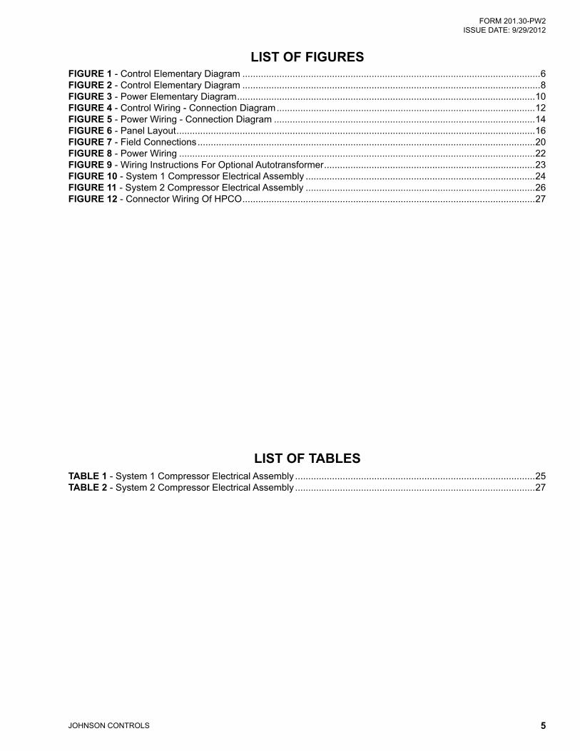
lIst oF FIGuRes
lIst oF tABles
FIGuRe 1 - Control Elementary Diagram .................................................................................................................6FIGuRe 2 - Control Elementary Diagram .................................................................................................................8FIGuRe 3 - Power Elementary Diagram .................................................................................................................10FIGuRe 4 - Control Wiring - Connection Diagram ..................................................................................................12FIGuRe 5 - Power Wiring - Connection Diagram ...................................................................................................14FIGuRe 6 - Panel Layout ........................................................................................................................................16FIGuRe 7 - Field Connections ................................................................................................................................20FIGuRe 8 - Power Wiring .......................................................................................................................................22FIGuRe 9 - Wiring Instructions For Optional Autotransformer ................................................................................23FIGuRe 10 - System 1 Compressor Electrical Assembly .......................................................................................24FIGuRe 11 - System 2 Compressor Electrical Assembly .......................................................................................26FIGuRe 12 - Connector Wiring Of HPCO ...............................................................................................................27
tABle 1 - System 1 Compressor Electrical Assembly ...........................................................................................25tABle 2 - System 2 Compressor Electrical Assembly ...........................................................................................27

FORM 201.30-PW2 ISSUE DATE: 9/29/2012
JOHNSON CONTROLS6
FIGuRe 1 - CONTROL ELEMENTARY DIAGRAM
CoNtRol eleMeNtARY DIAGRAM on
pag
es 1
0 &
11
on p
ages
10
& 1
1
LD16129a
FORM 201.30-PW2 ISSUE DATE: 9/29/2012
JOHNSON CONTROLS 7
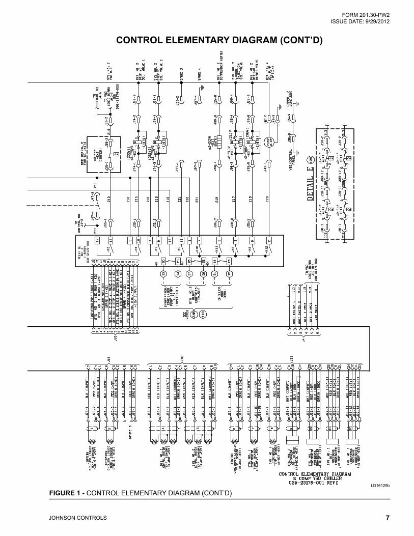
FIGuRe 1 - CONTROL ELEMENTARY DIAGRAM (CONT’D)
CoNtRol eleMeNtARY DIAGRAM (CoNt’D)
LD16129b

FORM 201.30-PW2 ISSUE DATE: 9/29/2012
JOHNSON CONTROLS8
CoNtRol eleMeNtARY DIAGRAM (CoNt’D)
FIGuRe 2 - CONTROL ELEMENTARY DIAGRAM
LD16130a

FORM 201.30-PW2 ISSUE DATE: 9/29/2012
JOHNSON CONTROLS 9
CoNtRol eleMeNtARY DIAGRAM (CoNt’D)
FIGuRe 2 - CONTROL ELEMENTARY DIAGRAM (CONT’D)
LD16130b

FORM 201.30-PW2 ISSUE DATE: 9/29/2012
JOHNSON CONTROLS10
PoWeR eleMeNtARY DIAGRAM
FIGuRe 3 - POWER ELEMENTARY DIAGRAM
LD16131a

FORM 201.30-PW2 ISSUE DATE: 9/29/2012
JOHNSON CONTROLS 11
FIGuRe 3 - POWER ELEMENTARY DIAGRAM (CONT’D)
PoWeR eleMeNtARY DIAGRAM (CoNt’D)
LD16131b

FORM 201.30-PW2 ISSUE DATE: 9/29/2012
JOHNSON CONTROLS12
CoNtRol WIRING - CoNNeCtIoN DIAGRAM
FIGuRe 4 - CONTROL WIRING - CONNECTION DIAGRAM
LD16132a

FORM 201.30-PW2 ISSUE DATE: 9/29/2012
JOHNSON CONTROLS 13
CoNtRol WIRING - CoNNeCtIoN DIAGRAM (CoNt’D)
LD16132b
FIGuRe 4 - CONTROL WIRING - CONNECTION DIAGRAM (CONT’D)

FORM 201.30-PW2 ISSUE DATE: 9/29/2012
JOHNSON CONTROLS14
PoWeR WIRING - CoNNeCtIoN DIAGRAM
FIGuRe 5 - POWER WIRING - CONNECTION DIAGRAM
LD16133a

FORM 201.30-PW2 ISSUE DATE: 9/29/2012
JOHNSON CONTROLS 15
PoWeR WIRING - CoNNeCtIoN DIAGRAM (CoNt’D)
FIGuRe 5 - POWER WIRING - CONNECTION DIAGRAM (CONT’D)
LD16133b

FORM 201.30-PW2 ISSUE DATE: 9/29/2012
JOHNSON CONTROLS16
PANel lAYout
FIGuRe 6 - PANEL LAYOUT
LD16134a
FORM 201.30-PW2 ISSUE DATE: 9/29/2012
JOHNSON CONTROLS 17
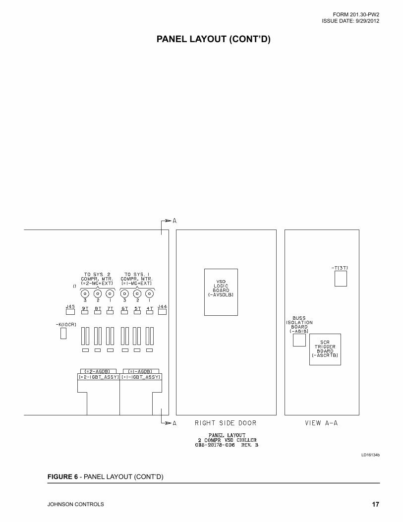
PANel lAYout (CoNt’D)
LD16134b
FIGuRe 6 - PANEL LAYOUT (CONT’D)

FORM 201.30-PW2 ISSUE DATE: 9/29/2012
JOHNSON CONTROLS18
THIS PAGE INTENTIONALLY LEFT BLANK.

FORM 201.30-PW2 ISSUE DATE: 9/29/2012
JOHNSON CONTROLS 19
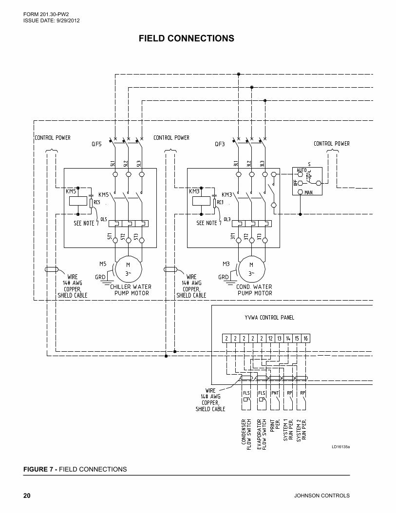
FIelD CoNNeCtIoNs
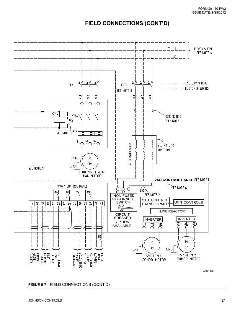
Notes1. All field wiring shall be in accordance with the
current edition of the relevant electric code as well as other applicable codes and specifications.
2. The Variable Speed Drive (VSD) shall be ground-ed in accordance with the related standards.
3. The branch circuit over current protection device for the YORK VSD must be a time delay type with a rating, which is the standard fuse/circuit breaker size required to protect the field supply wiring conductors per the relevant electric code as well as other applicable codes and specifica-tions.
4. The main power transformer should be adequate-ly sized such that the transformer voltage does not exceed 10% during unit start-up.
5. The YORK VSD power supply wiring ampac-ity shall be calculated as follows: Model YVWA Minimum Circuit Ampacity: 1.25 (JOB FLA) where 125 X (System 1 (RLA0) + (System 2 RLA0) + control transformer amps.
6. A removable cover plate with pilot knockouts is supplied for connection of power supply conduits.
7. Each field-conducted inductive load, i.e. relay coil, motor starter coil, etc. shall have a transient suppressor wired (by others) in parallel with its coil, physically located at the coil.
8. Control wiring and input power wiring out the VSD/Control Panel by the customer.
9. Water pump and cooling fan are the customer’s equipment, referenced only as wiring here.
10. The autotransformer is available as an op-tion, which is used only for a 200V/3P/60 Hz, 230/3P/60 Hz or 575V/3P/60 Hz power system.
The Enclosure Protection Class is IP23.
Fasten the wires with 1/2 in. (M12) hardware.Torque the screws 19-22 ft-lb (25.7-29.8 N-m), and wrap all of the wiring connections with high temperature tape (P/N 025-40165-000). The tape must cover the entire terminal surface.
Johnson Controls does not provide in-stallation and harnesses between the autotransformer and the VSD as well as the primary side of the autotransformer.
FORM 201.30-PW2 ISSUE DATE: 9/29/2012
JOHNSON CONTROLS20
FIelD CoNNeCtIoNs
LD16135a
FIGuRe 7 - FIELD CONNECTIONS
FORM 201.30-PW2 ISSUE DATE: 9/29/2012
JOHNSON CONTROLS 21
FIGuRe 7 - FIELD CONNECTIONS (CONT’D)
FIelD CoNNeCtIoNs (CoNt’D)
LD16135b
OPTION
VSD CONTROL PANEL
DISCONNECT NON-FUSED
SWITCH STD. CONTROLTRANSFORMER UNIT CONTROLS
LINE REACTOR
INVERTER INVERTERBREAKEROPTION
AVAILABLE
CIRCUIT
FORM 201.30-PW2 ISSUE DATE: 9/29/2012
JOHNSON CONTROLS22
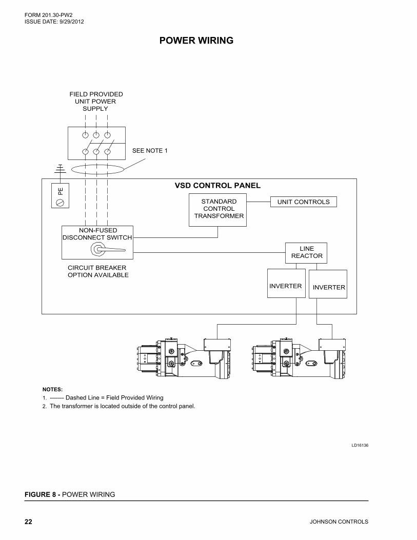
PoWeR WIRING
VSD CONTROL PANEL
STANDARDCONTROL
TRANSFORMER
UNIT CONTROLS
PE
LINEREACTOR
CIRCUIT BREAKER OPTION AVAILABLE
FIELD PROVIDEDUNIT POWER
SUPPLY
SEE NOTE 1
NON-FUSEDDISCONNECT SWITCH
NOTES:1. ------- Dashed Line = Field Provided Wiring2. The transformer is located outside of the control panel.
INVERTER INVERTER
LD16136
FIGuRe 8 - POWER WIRING

FORM 201.30-PW2 ISSUE DATE: 9/29/2012
JOHNSON CONTROLS 23
WIRING FoR oPtIoNAl AutotRANsFoRMeR
FIGuRe 9 - WIRING INSTRUCTIONS FOR OPTIONAL AUTOTRANSFORMER
VSD
Circuit Breaker Fuse 1L
IGBT
Tran
sfor
mer
Customer’sCircuit Breaker
xx
x
SYS COMPR 1
M3-
M3-
LD16709

FORM 201.30-PW2 ISSUE DATE: 9/29/2012
JOHNSON CONTROLS24
CoMPRessoR eleCtRICAl AsseMBlY
FIGuRe 10 - SYSTEM 1 COMPRESSOR ELECTRICAL ASSEMBLY
1
2
2
2
2
2
119GRD
112113
117
118109115
116
GRNRED
SYS1 HPCO1(CE)
SYS2 HPCO2(CE)
SYS1 HPCO(GB&UL)
BLKWHT
109112
113
112113109
GRD101a102a103aGRD
101b102b103bGRD
12 11 10
GRD
TO VSD PANEL(IC)
TO VSD PANEL(IA)
TO VSD PANEL(IB)
SEE TABLE A(OPTION)
SEE TABLE A
SYS1 STEP VI VALVE1 (OPTION)
SYS1 STEP VI VALVE2 (OPTION)
SYS1 COMP. HEATER
SYS1 LIQUID INJECTION VALVE
(OPTION)
SYS1 HGBP VALVE1
(OPTION)
TOVSD PANEL
(SYS1 COMP. TEMP.)
115 2 2 2 2 2119 117 118116
9 8 76 5 43 2 1
1 2 3
1
2
3
C
4 5 67 8 9
10 11 12
234
T1
T2
T3
2 134
LD16464a
FORM 201.30-PW2 ISSUE DATE: 9/29/2012
JOHNSON CONTROLS 25
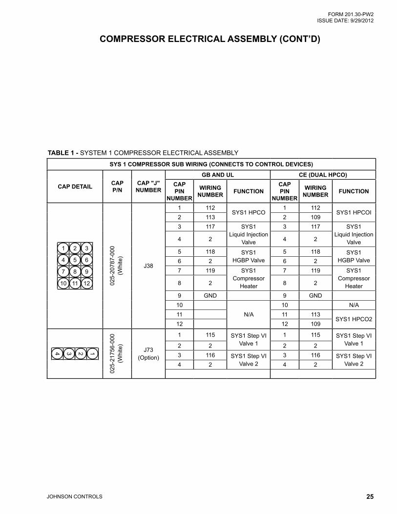
CoMPRessoR eleCtRICAl AsseMBlY (CoNt’D)
tABle 1 - SYSTEM 1 COMPRESSOR ELECTRICAL ASSEMBLY
sYs 1 CoMPRessoR suB WIRING (CoNNeCts to CoNtRol DevICes)
CAP DetAIl CAP P/N
CAP "J" NuMBeR
GB AND ul Ce (DuAl hPCo)CAP PIN
NuMBeR
WIRING NuMBeR FuNCtIoN
CAP PIN
NuMBeR
WIRING NuMBeR FuNCtIoN
1 2 3
4 5 6
7 8 9
10 11 12 025-
2078
7-00
0 (W
hite
)
J38
1 112SYS1 HPCO
1 112SYS1 HPCOI
2 113 2 1093 117 SYS1
Liquid Injection Valve
3 117 SYS1 Liquid Injection
Valve4 2 4 2
5 118 SYS1 HGBP Valve
5 118 SYS1 HGBP Valve6 2 6 2
7 119 SYS1 Compressor
Heater
7 119 SYS1 Compressor
Heater8 2 8 2
9 GND 9 GND10
N/A10 N/A
11 11 113SYS1 HPCO2
12 12 109
1234
025-
2175
6-00
0 (W
hite
)
J73 (Option)
1 115 SYS1 Step VI Valve 1
1 115 SYS1 Step VI Valve 12 2 2 2
3 116 SYS1 Step VI Valve 2
3 116 SYS1 Step VI Valve 24 2 4 2

FORM 201.30-PW2 ISSUE DATE: 9/29/2012
JOHNSON CONTROLS26
CoMPRessoR eleCtRICAl AsseMBlY
FIGuRe 11 - SYSTEM 2 COMPRESSOR ELECTRICAL ASSEMBLY
1
2
2
2
2
2
219GRD212213
217
218209215
216
GRNRED
SYS2 HPCO2(CE)
SYS2 HPCO1(CE)
SYS2 HPCO(GB&UL)
BLKWHT
209212
213
212213209
GRD201a202a203aGRD
201b202b203bGRD
12 11 10
GRD
TO VSD PANEL(2C)
TO VSD PANEL(2A)
TO VSD PANEL(2B)
SEE TABLE A(OPTION)
SEE TABLE A
SYS2 STEP VI VALVE1 (OPTION)
SYS2 STEP VI VALVE2 (OPTION)
SYS2 COMP. HEATER
SYS2 LIQUID INJECTION VALVE
(OPTION)
SYS2 HGBP VALVE1
(OPTION)
TOVSD PANEL
(SYS2 COMP. TEMP.)
215 2 2 2 2 2219 217 218216
9 8 76 5 43 2 1
1 2 3
1
2
3
C
4 5 67 8 9
10 11 12
234
T1
T2
T3
2 134
LD16465a

FORM 201.30-PW2 ISSUE DATE: 9/29/2012
JOHNSON CONTROLS 27
CoMPRessoR eleCtRICAl AsseMBlY (CoNt’D)
tABle 2 - SYSTEM 2 COMPRESSOR ELECTRICAL ASSEMBLY
sYs 2 CoMPRessoR suB WIRING (CoNNeCts to CoNtRol DevICes)
CAP DetAIl CAP P/N
CAP "J" NuMBeR
GB AND ul Ce (DuAl hPCo)CAP PIN
NuMBeR
WIRING NuMBeR FuNCtIoN
CAP PIN
NuMBeR
WIRING NuMBeR FuNCtIoN
1 2 3
4 5 6
7 8 9
10 11 12 025-
2078
7-00
0 (W
hite
)
J39
1 212SYSI HPCO
1 212SYS2 HPCOI
2 213 2 2093 217 SYS2
Liquid Injection Valve
3 217 SYS2 Liquid Injection
Valve4 2 4 2
5 218 SYS2 HGBP Valve
5 218 SYS2 HGBP Valve6 2 6 2
7 219 SYS2 Compressor
Heater
7 219 SYS2 Compressor
Heater8 2 8 2
9 GND 9 GND10
N/A10 N/A
11 11 213SYS2 HPCO2
12 12 209
1234
025-
2175
6-00
0 (W
hite
)
J74 (Option)
1 215 SYS2 Step VI Valve 1
1 215 SYS2 Step VI Valve 12 2 2 2
3 216 SYS2 Step VI Valve 2
3 216 SYS2 Step VI Valve 24 2 4 2
FIGuRe 12 - CONNECTOR WIRING OF HPCO
LD16466

P.O. Box 1592, York, Pennsylvania USA 17405-1592 Subject to change without notice. Printed in USACopyright © by Johnson Controls 2012 ALL RIGHTS RESERVEDForm 201.30-PW2 (912)Issue Date: September 29, 2012Supersedes 201.30-PW2 (512)
800-861-1001www.johnsoncontrols.com


![Untitled-1 [ ] · PDF fileOTIS GEN2 MEMCO REM Wiring Loom Key Features + No wiring required into the Memcom unit - all connections to the unit are pre-wired + All connections required](https://static.fdocuments.us/doc/165x107/5aac32ea7f8b9ac55c8c9da0/untitled-1-gen2-memco-rem-wiring-loom-key-features-no-wiring-required-into.jpg)