Fibre Optics 2
21
FIBRE OPTICS COMMUNICATION PRESENTED BY :- AJAY RANA B.TECH 3 RD YEAR ROLL NO. 0803231011
-
Upload
ahmed-awan -
Category
Documents
-
view
220 -
download
0
Transcript of Fibre Optics 2

8/6/2019 Fibre Optics 2
http://slidepdf.com/reader/full/fibre-optics-2 1/21
FIBRE OPTICS
COMMUNICATION
PRESENTED BY :-AJAY RANA
B.TECH 3RD YEAR
ROLL NO. 0803231011
8/6/2019 Fibre Optics 2
http://slidepdf.com/reader/full/fibre-optics-2 2/21
INTRODUCTION
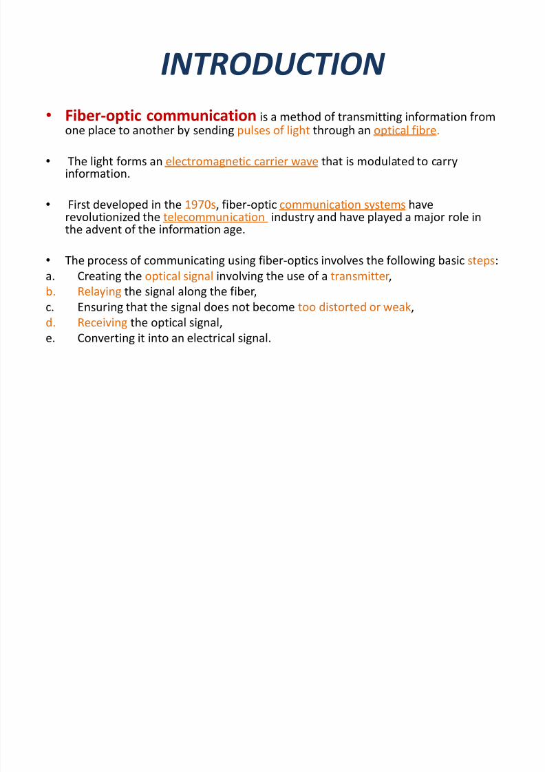
� Fiber-optic communication is a method of transmitting information fromone place to another by sending pulses of light through an optical f ibre.
� The light forms an electromagnetic carrier wave that is modulated to carryinformation.
� First developed in the 1970s, f iber-optic communication systems haverevolutionized the telecommunication industry and have played a major role inthe advent of the information age.
� The process of communicating using f iber-optics involves the following basic steps:
a. Creating the optical signal involving the use of a transmitter,
b. Relaying the signal along the f iber,
c. Ensuring that the signal does not become too distorted or weak,
d. Receiving the optical signal,
e. Converting it into an electrical signal.
8/6/2019 Fibre Optics 2
http://slidepdf.com/reader/full/fibre-optics-2 3/21
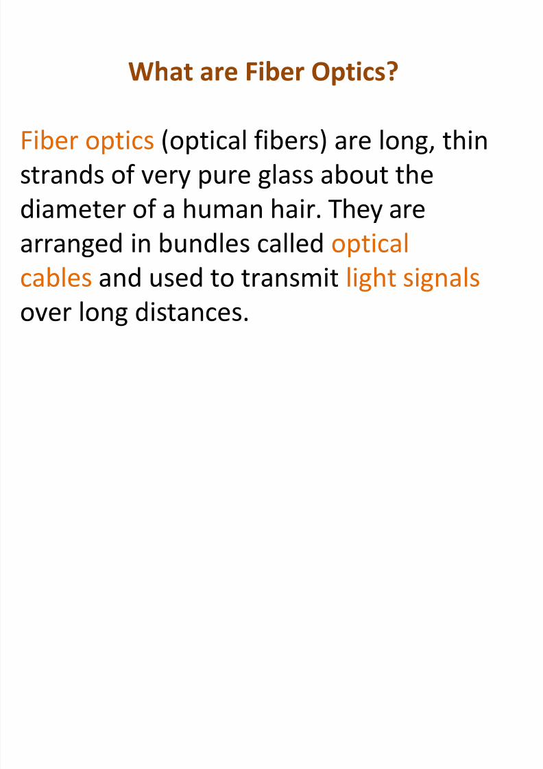
What are Fiber Optics?
Fiber optics (optical f ibers) are long, thin
strands of very pure glass about the
diameter of a human hair. They are
arranged in bundles called optical
cables and used to transmit light signalsover long distances.

8/6/2019 Fibre Optics 2
http://slidepdf.com/reader/full/fibre-optics-2 4/21
Optical Fiber
� Core
± Glass or plastic with a higher index of
refraction than the cladding
± Carries the signal
� Cladding
± Glass or plastic with a lower index of
refraction than the core
� Buffer
± Protects the f iber from damage and
moisture
� Jacket
± Holds one or more f ibers in a cable
8/6/2019 Fibre Optics 2
http://slidepdf.com/reader/full/fibre-optics-2 5/21

8/6/2019 Fibre Optics 2
http://slidepdf.com/reader/full/fibre-optics-2 6/21
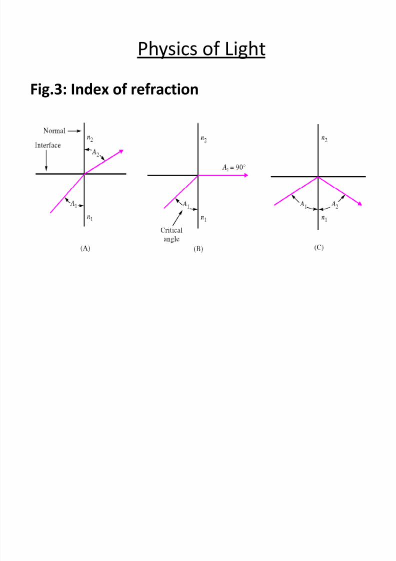
� Fig. 3A shows how a light ray passing from material 1 tomaterial 2 is refracted in material 2 when A1 is less than thecritical angle.
� Fig. 3B shows the condition that exists when A1 is at thecritical angle and angle A2 is at 900. The light is directedalong the boundary between the 2 materials.
� Fig. 3C shows that any light ray incident at an angle greaterthan A1 of Fig. 3B will be reflected back into material 1 withA2 equal to A1.
Physics of Light

8/6/2019 Fibre Optics 2
http://slidepdf.com/reader/full/fibre-optics-2 7/21
Fig 1: Fiber for light beam propagation
Reflection in Optical Fiber

8/6/2019 Fibre Optics 2
http://slidepdf.com/reader/full/fibre-optics-2 8/21
� From fig. 1, the light rays are reflected from the
inner walls as they propagate lengthwise along the
fiber.
� A single light beam can be modulated
simultaneously by hundreds, or even thousands, of
independent signals.
Reflection in Optical Fiber
8/6/2019 Fibre Optics 2
http://slidepdf.com/reader/full/fibre-optics-2 9/21
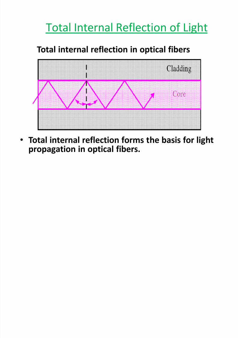
Total internal reflection in optical fibers
� Total internal reflection forms the basis for lightpropagation in optical fibers.
Total Internal Reflection of Light

8/6/2019 Fibre Optics 2
http://slidepdf.com/reader/full/fibre-optics-2 10/21
� Mode simply means path from which light ispropagated.
� If there is only one path for light to take down thecable, it is called single mode.
� If there is more than one path, it is called multi-mode.
Mode of Propagation
8/6/2019 Fibre Optics 2
http://slidepdf.com/reader/full/fibre-optics-2 11/21

8/6/2019 Fibre Optics 2
http://slidepdf.com/reader/full/fibre-optics-2 12/21

8/6/2019 Fibre Optics 2
http://slidepdf.com/reader/full/fibre-optics-2 13/21
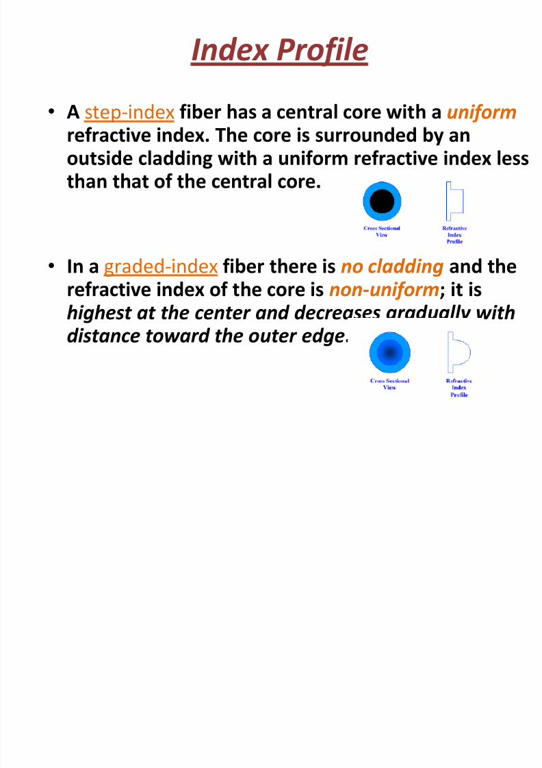
� The light rays that strike the core/cladding interface at anangle greater than the critical angle are propagated downthe core in a zigzag fashion, continuously reflecting off theinterface boundary.
� There are many paths that a light ray may follow as itpropagates down the fiber. As a result, all light rays do notfollow the same path and hence do not take the sameamount of time to travel the length of the fiber.
Multi-mode Step-Index Fiber

8/6/2019 Fibre Optics 2
http://slidepdf.com/reader/full/fibre-optics-2 14/21

8/6/2019 Fibre Optics 2
http://slidepdf.com/reader/full/fibre-optics-2 15/21
15
Advantages of f iber optics
Much Higher Bandwidth (Gbps) - Thousands of channels can be
multiplexed together over one strand of f iber
Immunity to Noise - Immune to electromagnetic interference (EMI).
Safety - Doesnt transmit electrical signals, making it safe inenvironments like a gas pipeline.
High Security - Impossible to tap into.
Less Loss - Repeaters can be spaced 75 miles apart (f ibers can be made
to have only 0.2 dB/km of attenuation)
Reliability -More resilient than copper in extreme environmentalconditions.
Size - Lighter and more compact than copper.
Flexibility - Unlike impure, brittle glass, f iber is physically very flexible.
.
8/6/2019 Fibre Optics 2
http://slidepdf.com/reader/full/fibre-optics-2 16/21
8/6/2019 Fibre Optics 2
http://slidepdf.com/reader/full/fibre-optics-2 17/21
Present Telecommunications
Internet Access
Cable and Satellite Television
Decorative Light Source

8/6/2019 Fibre Optics 2
http://slidepdf.com/reader/full/fibre-optics-2 18/21
Optical Fibre In Telecommunication
BSNL has the largest optical f ibre cable network in the country,
comprising at least 600,000 route kilometres covering all state
capitals and district headquarters. The f irm also operates around
42,000 telecom towers.
Tata Teleservices plans to spend Rs.2 billion to raise its optical
f ibre network to 5,000 km in the east byMarch 2006, the company.
Reliance fully-owned subsidiary of the his Industries, will lay a
4000 route km optical f iber network in Uttar Pradesh, investing 40
billion.

8/6/2019 Fibre Optics 2
http://slidepdf.com/reader/full/fibre-optics-2 19/21

8/6/2019 Fibre Optics 2
http://slidepdf.com/reader/full/fibre-optics-2 20/21
The Internet

8/6/2019 Fibre Optics 2
http://slidepdf.com/reader/full/fibre-optics-2 21/21
THANK YOU