Reassembling Fractured Objects by Geometric Matching - CiteSeer
BK3254601-00 FThird party information brought to
you courtesy of Dell EMC.
User’s GuideFibre Channel Adapter
QLE2740-DEL, QLE2740L-DEL,QLE2742-DEL, QLE2742L-DEL,
and QME2742-DEL

ii BK3254601-00 F
User’s Guide—Fibre Channel AdapterQLE274x-DEL, QLE274xL-DEL, QME2742-DEL
Document Revision History
Revision A, March 21, 2016
Revision B, April 19, 2016
Revision C, February 1, 2017
Revision D, August 24, 2017
Revision E, December 19, 2017
Revision F, April 13, 2018
Changes Sections Affected
Added support for QME2742-DEL 32Gb Fibre Channel mezzanine card
Throughout
Added support for Windows 2008 R2 SP1 “Windows” on page xiv
Added support for RHEL 7.5, SLES 15; removed support for RHEL 6.6, 6.9, 7.2, 7.3 and SLES 11 SP4
“Linux” on page xiv
Added support for ESXi 6.5 U2 and ESXi 6.7 “VMware” on page xiv
Added ESXi 6.7 “Installing the ESXi 6.7, 6.5, and 6.0 U2 Fibre Channel Driver” on page 16“Updating an Existing Driver or Installing a New Driver for an Existing ESXi 6.7, 6.5 or 6.0 U2/U3 Installation with esxcli” on page 17“Installing the CIM Provider on an ESXi 6.7, 6.5, or 6.0 U2/U3 Host” on page 25
Added SLES 15 “Building the Driver for SLES 12 and SLES 15” on page 14
Added VM-ID Configuration “Configuring VM-ID” on page 31
Updated the instructions for downloading the Superinstaller from the Cavium Web site.
“Installing the Agents from the Cavium Web Site” on page 116
iii BK3254601-00 F
Table of Contents
Introduction
Intended Audience . . . . . . . . . . . . . . . . . . . . . . . . . . . . . . . . . . . . . . . . . . . . ixUser’s Guide Content . . . . . . . . . . . . . . . . . . . . . . . . . . . . . . . . . . . . . . . . . . xRelated Materials . . . . . . . . . . . . . . . . . . . . . . . . . . . . . . . . . . . . . . . . . . . . . xDocumentation Conventions . . . . . . . . . . . . . . . . . . . . . . . . . . . . . . . . . . . . xiFunctionality and Features . . . . . . . . . . . . . . . . . . . . . . . . . . . . . . . . . . . . . . xiii
Functional Description . . . . . . . . . . . . . . . . . . . . . . . . . . . . . . . . . . . . . xiiiKey Features . . . . . . . . . . . . . . . . . . . . . . . . . . . . . . . . . . . . . . . . . . . . xiiiSupported Operating Systems . . . . . . . . . . . . . . . . . . . . . . . . . . . . . . xiv
Windows . . . . . . . . . . . . . . . . . . . . . . . . . . . . . . . . . . . . . . . . . . . xivLinux . . . . . . . . . . . . . . . . . . . . . . . . . . . . . . . . . . . . . . . . . . . . . . xivVMware . . . . . . . . . . . . . . . . . . . . . . . . . . . . . . . . . . . . . . . . . . . xivCitrix XenServer . . . . . . . . . . . . . . . . . . . . . . . . . . . . . . . . . . . . . xiv
1 Hardware Installation
Hardware and Software Requirements . . . . . . . . . . . . . . . . . . . . . . . . . . . . 1Safety Precautions . . . . . . . . . . . . . . . . . . . . . . . . . . . . . . . . . . . . . . . . . . . . 1Pre-Installation Checklist . . . . . . . . . . . . . . . . . . . . . . . . . . . . . . . . . . . . . . . 2PCIe Bus Slot Considerations . . . . . . . . . . . . . . . . . . . . . . . . . . . . . . . . . . . 2Installing the Adapter . . . . . . . . . . . . . . . . . . . . . . . . . . . . . . . . . . . . . . . . . . 3Connecting to the SAN. . . . . . . . . . . . . . . . . . . . . . . . . . . . . . . . . . . . . . . . . 4
2 Driver Installation and Configuration
Windows Driver Installation and Configuration. . . . . . . . . . . . . . . . . . . . . . . 5Running the Dell Update Package in the GUI . . . . . . . . . . . . . . . . . . . 6Running the Dell Update Package from the Command Line. . . . . . . . 11
Examples . . . . . . . . . . . . . . . . . . . . . . . . . . . . . . . . . . . . . . . . . . 12Linux Driver Installation and Configuration. . . . . . . . . . . . . . . . . . . . . . . . . . 12
Installation Overview . . . . . . . . . . . . . . . . . . . . . . . . . . . . . . . . . . . . . . 13Installing the Linux Fibre Channel Driver. . . . . . . . . . . . . . . . . . . . . . . 13
Building the Driver for 7.x . . . . . . . . . . . . . . . . . . . . . . . . . . . . . . 13Building the Driver for SLES 12 and SLES 15 . . . . . . . . . . . . . . 14
VMware Driver Installation and Configuration . . . . . . . . . . . . . . . . . . . . . . . 16Installation Overview . . . . . . . . . . . . . . . . . . . . . . . . . . . . . . . . . . . . . . 16
User’s Guide—Fibre Channel Adapter QLE274x-DEL, QLE274xL-DEL, QME2742-DEL
iv BK3254601-00 F
Installing the ESXi 6.7, 6.5, and 6.0 U2 Fibre Channel Driver. . . . . . . 16Updating an Existing Driver or Installing a New Driver for an
Existing ESXi 6.7, 6.5 or 6.0 U2/U3 Installation with esxcli . . . 17Verifying the Version of the Installed Driver . . . . . . . . . . . . . . . . 17
Installing QConvergeConsole VMware vCenter Server Plug-in . . . . . 18Installation Package Contents . . . . . . . . . . . . . . . . . . . . . . . . . . 18Installing QConvergeConsole VMware vCenter Server Plug-in . 19Plug-in Unregistration from a Manual Install. . . . . . . . . . . . . . . . 23Uninstalling the QConvergeConsole VMware vCenter Server
Plug-in . . . . . . . . . . . . . . . . . . . . . . . . . . . . . . . . . . . . . . . . . . . 24Installing the QLogic Adapter CIM Provider . . . . . . . . . . . . . . . . 24Uninstalling the QLogic Adapter CIM Provider . . . . . . . . . . . . . . 28
Installing . . . . . . . . . . . . . . . . . . . . . . . . . . . . . . . . . . . . . . . . . . . . . . . 29Uninstalling the QConvergeConsole VMware vCenter Server
Plug-in . . . . . . . . . . . . . . . . . . . . . . . . . . . . . . . . . . . . . . . . . . . 30Configuring VM-ID. . . . . . . . . . . . . . . . . . . . . . . . . . . . . . . . . . . . . . . . 31
3 Fibre Channel Configuration
Updating the Dell Firmware . . . . . . . . . . . . . . . . . . . . . . . . . . . . . . . . . . . . . 33Running the Firmware Update by Double-Clicking . . . . . . . . . . . . . . . 33Running the Firmware Update from the Command Line . . . . . . . . . . . 36
Using Fast!UTIL for Custom Configuration. . . . . . . . . . . . . . . . . . . . . . . . . . 37Configuration Settings . . . . . . . . . . . . . . . . . . . . . . . . . . . . . . . . . . . . . 37
Adapter Settings . . . . . . . . . . . . . . . . . . . . . . . . . . . . . . . . . . . . . 38Selectable Boot Settings . . . . . . . . . . . . . . . . . . . . . . . . . . . . . . 39Restore Default Settings. . . . . . . . . . . . . . . . . . . . . . . . . . . . . . . 40Raw NVRAM Data . . . . . . . . . . . . . . . . . . . . . . . . . . . . . . . . . . . 40Advanced Adapter Settings . . . . . . . . . . . . . . . . . . . . . . . . . . . . 40
Scan Fibre Devices . . . . . . . . . . . . . . . . . . . . . . . . . . . . . . . . . . . . . . . 41Fibre Disk Utility. . . . . . . . . . . . . . . . . . . . . . . . . . . . . . . . . . . . . . . . . . 42Loopback Data Test. . . . . . . . . . . . . . . . . . . . . . . . . . . . . . . . . . . . . . . 42Select Adapter . . . . . . . . . . . . . . . . . . . . . . . . . . . . . . . . . . . . . . . . . . . 42Exit Fast!UTIL . . . . . . . . . . . . . . . . . . . . . . . . . . . . . . . . . . . . . . . . . . . 42
Setting Fibre Channel Adapter Parameters . . . . . . . . . . . . . . . . . . . . . . . . . 43Setting Fibre Channel Adapter Parameters with QConvergeConsole
GUI . . . . . . . . . . . . . . . . . . . . . . . . . . . . . . . . . . . . . . . . . . . . . . . . . . 43Setting Fibre Channel Adapter Parameters with Interactive
QConvergeConsole CLI . . . . . . . . . . . . . . . . . . . . . . . . . . . . . . . . . . 43Setting Fibre Channel Adapter Parameters with Noninteractive
QConvergeConsole CLI . . . . . . . . . . . . . . . . . . . . . . . . . . . . . . . . . . 44Configuring Target Persistent Binding . . . . . . . . . . . . . . . . . . . . . . . . . . . . . 44
User’s Guide—Fibre Channel Adapter QLE274x-DEL, QLE274xL-DEL, QME2742-DEL
v BK3254601-00 F
Configuring Persistent Binding with QConvergeConsole GUI. . . . . . . 44Configuring Persistent Binding with Interactive QConvergeConsole
CLI. . . . . . . . . . . . . . . . . . . . . . . . . . . . . . . . . . . . . . . . . . . . . . . . . . . 45Configuring Persistent Binding with Noninteractive
QConvergeConsole CLI . . . . . . . . . . . . . . . . . . . . . . . . . . . . . . . . . . 45Configuring Boot Devices. . . . . . . . . . . . . . . . . . . . . . . . . . . . . . . . . . . . . . . 46
Configuring Boot Devices with QConvergeConsole GUI. . . . . . . . . . . 46Configuring Boot Devices with Interactive QConvergeConsole CLI . . 46Configuring Boot Devices with Noninteractive QConvergeConsole
CLI. . . . . . . . . . . . . . . . . . . . . . . . . . . . . . . . . . . . . . . . . . . . . . . . . . . 47Configuring Boot Devices with the BIOS. . . . . . . . . . . . . . . . . . . . . . . 47
Configuring Virtual Ports (NPIV). . . . . . . . . . . . . . . . . . . . . . . . . . . . . . . . . . 47Configuring NPIV with QConvergeConsole GUI . . . . . . . . . . . . . . . . . 47Configuring NPIV with Interactive QConvergeConsole CLI. . . . . . . . . 48Configuring NPIV with Noninteractive QConvergeConsole CLI . . . . . 48Configuring NPIV Quality of Service . . . . . . . . . . . . . . . . . . . . . . . . . . 49
Setting QoS by Bandwidth . . . . . . . . . . . . . . . . . . . . . . . . . . . . . 50Setting QoS by Priority . . . . . . . . . . . . . . . . . . . . . . . . . . . . . . . . 53
Configuring Fibre Channel Driver Parameters . . . . . . . . . . . . . . . . . . . . . . . 54Configuring Fibre Channel Driver Parameters with
QConvergeConsole GUI . . . . . . . . . . . . . . . . . . . . . . . . . . . . . . . . . . 54Configuring Fibre Channel Driver Parameters with Interactive
QConvergeConsole CLI . . . . . . . . . . . . . . . . . . . . . . . . . . . . . . . . . . 54Configuring Fibre Channel Driver Parameters with Noninteractive
QConvergeConsole CLI . . . . . . . . . . . . . . . . . . . . . . . . . . . . . . . . . . 55Configuring Fibre Channel Driver Parameters with
QConvergeConsole VMware vCenter Server Plug-in . . . . . . . . . . . . 55Configuring Selective LUNs . . . . . . . . . . . . . . . . . . . . . . . . . . . . . . . . . . . . . 55Configuring OoOFR . . . . . . . . . . . . . . . . . . . . . . . . . . . . . . . . . . . . . . . . . . . 56
Configuring OoOFR with QCC GUI . . . . . . . . . . . . . . . . . . . . . . . . . . . 56Configuring OoOFR with Interactive QCC CLI . . . . . . . . . . . . . . . . . . 56Configuring OoOFR with Noninteractive QCC CLI . . . . . . . . . . . . . . . 56
Configuring the UEFI Driver . . . . . . . . . . . . . . . . . . . . . . . . . . . . . . . . . . . . . 57Setting an FA-PWWN. . . . . . . . . . . . . . . . . . . . . . . . . . . . . . . . . . . . . . . . . . 64
Setting the FA-PWWN from the Adapter . . . . . . . . . . . . . . . . . . . . . . . 64Setting FA-PWWN with QConvergeConsole GUI. . . . . . . . . . . . 65Setting FA-PWWN with QConvergeConsole CLI . . . . . . . . . . . . 66Setting FA-PWWN with QConvergeConsole VMware Plug-ins . 68
User’s Guide—Fibre Channel Adapter QLE274x-DEL, QLE274xL-DEL, QME2742-DEL
vi BK3254601-00 F
Setting the FA-PWWN from the Brocade Switch. . . . . . . . . . . . . . . . . 69Setting the FA-PWWN from the Switch . . . . . . . . . . . . . . . . . . . 69Setting the Static FA-PWWN from the Switch . . . . . . . . . . . . . . 69
Configuring and Verifying FA-BLD . . . . . . . . . . . . . . . . . . . . . . . . . . . . . . . . 70Configuring FA-BLD from the Adapter . . . . . . . . . . . . . . . . . . . . . . . . . 70
Enabling Host Bus Adapter Port BIOS and Fabric-assigned Boot LUN with QConvergeConsole GUI . . . . . . . . . . . . . . . . . 71
Configuring the Adapter and Boot Devices with QConvergeConsole CLI . . . . . . . . . . . . . . . . . . . . . . . . . . . . . . 73
Configuring a Zone in a Brocade Switch . . . . . . . . . . . . . . . . . . 74Verifying that FA-BLD is Operational . . . . . . . . . . . . . . . . . . . . . . . . . . 75Adapter Side Restrictions . . . . . . . . . . . . . . . . . . . . . . . . . . . . . . . . . . 76
Using a Fabric-Assigned Boot LUN . . . . . . . . . . . . . . . . . . . . . . . . . . . . . . . 76Using a Fabric-Assigned Boot LUN in QConvergeConsole GUI . . . . . 76Using a Fabric-Assigned Boot LUN in Interactive
QConvergeConsole CLI . . . . . . . . . . . . . . . . . . . . . . . . . . . . . . . . . . 76Using a Fabric-Assigned Boot LUN with Noninteractive
QConvergeConsole CLI . . . . . . . . . . . . . . . . . . . . . . . . . . . . . . . . . . 77Using a Fabric-Assigned Boot LUN with QConvergeConsole
Plug-ins . . . . . . . . . . . . . . . . . . . . . . . . . . . . . . . . . . . . . . . . . . . . . . . 77Running Diagnostics—Fibre Channel Ping and Trace Route . . . . . . . . . . . 78
Pinging and Viewing Trace of Routing Using Topology Map . . . . . . . . 79Running a Fibre Channel CT Ping Test . . . . . . . . . . . . . . . . . . . . . . . . 79
Running a Fibre Channel CT Ping from QConvergeConsole GUI . . . . . . . . . . . . . . . . . . . . . . . . . . . . . . . . . . . . . . . . . . . . . . 79
Running a Fibre Channel CT Ping from QConvergeConsole CLI . . . . . . . . . . . . . . . . . . . . . . . . . . . . . . . . . . . . . . . . . . . . . . 81
Running a Fibre Channel CT Ping from QConvergeConsole VMware Plug-ins . . . . . . . . . . . . . . . . . . . . . . . . . . . . . . . . . . . 81
Fibre Channel Trace Route . . . . . . . . . . . . . . . . . . . . . . . . . . . . . . . . . 82Configuring CS_CTL QoS . . . . . . . . . . . . . . . . . . . . . . . . . . . . . . . . . . . . . . 83
CS_CTL QoS Features . . . . . . . . . . . . . . . . . . . . . . . . . . . . . . . . . . . . 83Enabling CS_CTL QoS Mode for the Initiator and Target Ports . . . . . 84Verifying and Confirming CS_CTL Mode Setup for Each Port . . . . . . 84Creating a Virtual Port from the Adapter’s Port in
QConvergeConsole GUI . . . . . . . . . . . . . . . . . . . . . . . . . . . . . . . . . . 85Setting the QoS Priority Level for a Virtual Port in
QConvergeConsole GUI . . . . . . . . . . . . . . . . . . . . . . . . . . . . . . . . . . 86Configuring End-to-End CS_CTL QoS. . . . . . . . . . . . . . . . . . . . . . . . . . . . . 87
Configuring CS_CTL QoS on the Switch. . . . . . . . . . . . . . . . . . . . . . . 87Configuring CS_CTL QoS on the Storage Device. . . . . . . . . . . . . . . . 88

User’s Guide—Fibre Channel Adapter QLE274x-DEL, QLE274xL-DEL, QME2742-DEL
vii BK3254601-00 F
Changing the QoS Priority Levels . . . . . . . . . . . . . . . . . . . . . . . . . . . . 88Changing the Priority Levels in Windows . . . . . . . . . . . . . . . . . . 88Changing the Priority Levels in VMware ESXi . . . . . . . . . . . . . . 91
Configuring FDMI . . . . . . . . . . . . . . . . . . . . . . . . . . . . . . . . . . . . . . . . . . . . . 92Brocade Switch FOS CLI. . . . . . . . . . . . . . . . . . . . . . . . . . . . . . . . . . . 93Brocade Fabric Features . . . . . . . . . . . . . . . . . . . . . . . . . . . . . . . . . . . 94FDMI Enhancements Support . . . . . . . . . . . . . . . . . . . . . . . . . . . . . . . 95
Enabling QLogic Forward Error Correction . . . . . . . . . . . . . . . . . . . . . . . . . 96FEC Process Overview . . . . . . . . . . . . . . . . . . . . . . . . . . . . . . . . . . . . 97Enabling QLogic FEC . . . . . . . . . . . . . . . . . . . . . . . . . . . . . . . . . . . . . 98
Running Extended Link Service Commands . . . . . . . . . . . . . . . . . . . . . . . . 98Link Cable Beacon Extended Link Service Command . . . . . . . . . . . . 99Read Diagnostic Parameters Extended Link Service Command . . . . 99
A Troubleshooting
Fibre Channel Diagnostics . . . . . . . . . . . . . . . . . . . . . . . . . . . . . . . . . . . . . . 101Fibre Channel Diagnostics Using QConvergeConsole GUI . . . . . . . . 101Fibre Channel Diagnostics Using Interactive QConvergeConsole CLI 103Fibre Channel Diagnostics Using Noninteractive
QConvergeConsole CLI . . . . . . . . . . . . . . . . . . . . . . . . . . . . . . . . . . 103Fibre Channel Troubleshooting Diagram . . . . . . . . . . . . . . . . . . . . . . . . . . . 104Troubleshooting with a Diagnostic Port (D_Port) . . . . . . . . . . . . . . . . . . . . . 105
Configuring D_Port on a Brocade Fibre Channel 16G or 32G Switch. 107Checking D_Port Results from a Brocade Fibre Channel 16G or
32G Switch . . . . . . . . . . . . . . . . . . . . . . . . . . . . . . . . . . . . . . . . . . . . 107Verifying D_Port Mode with QConvergeConsole GUI . . . . . . . . . . . . . 109Verifying D_Port Mode with Interactive QConvergeConsole CLI . . . . 110Verifying D_Port Mode with Noninteractive QConvergeConsole CLI . 111Verifying D_Port Mode with QConvergeConsole Plug-ins. . . . . . . . . . 111
B Specifications
Physical Characteristics . . . . . . . . . . . . . . . . . . . . . . . . . . . . . . . . . . . . . . . . 112Power Requirements . . . . . . . . . . . . . . . . . . . . . . . . . . . . . . . . . . . . . . . . . . 112Standards Specifications . . . . . . . . . . . . . . . . . . . . . . . . . . . . . . . . . . . . . . . 113Interface Specifications . . . . . . . . . . . . . . . . . . . . . . . . . . . . . . . . . . . . . . . . 113Environmental Specifications . . . . . . . . . . . . . . . . . . . . . . . . . . . . . . . . . . . . 113
C QConvergeConsole GUI
Introduction to QConvergeConsole GUI. . . . . . . . . . . . . . . . . . . . . . . . . . . . 114Downloading QConvergeConsole Documentation. . . . . . . . . . . . . . . . . . . . 115Downloading and Installing Management Agents . . . . . . . . . . . . . . . . . . . . 115

User’s Guide—Fibre Channel Adapter QLE274x-DEL, QLE274xL-DEL, QME2742-DEL
viii BK3254601-00 F
Installing the Agents from the Cavium Web Site . . . . . . . . . . . . . . . . . 116Installing the Agents Using the Built-in Agent Installer . . . . . . . . . . . . 116
Installing QConvergeConsole GUI . . . . . . . . . . . . . . . . . . . . . . . . . . . . . . . . 116Installing QConvergeConsole in a Windows Environment . . . . . . . . . 117Installing QConvergeConsole in a Linux Environment . . . . . . . . . . . . 118Installing QConvergeConsole in Silent Mode . . . . . . . . . . . . . . . . . . . 119
What Is in the QConvergeConsole Help System . . . . . . . . . . . . . . . . . . . . . 119
D Regulatory Information
Warranty . . . . . . . . . . . . . . . . . . . . . . . . . . . . . . . . . . . . . . . . . . . . . . . . . . . . 121Regulatory and Compliance Information . . . . . . . . . . . . . . . . . . . . . . . . . . . 121
Laser Safety, FDA Notice . . . . . . . . . . . . . . . . . . . . . . . . . . . . . . . . . . 121Agency Certification. . . . . . . . . . . . . . . . . . . . . . . . . . . . . . . . . . . . . . . 122
EMI and EMC Requirements . . . . . . . . . . . . . . . . . . . . . . . . . . . 122Product Safety Compliance . . . . . . . . . . . . . . . . . . . . . . . . . . . . 123
ix BK3254601-00 F
Introduction
This introductory chapter provides a list of the covered models, describes the intended audience and contents of this guide, lists related documents and the document conventions, describes the product functionality and features, and lists the supported OSs.
This user’s guide covers the following products:
QLogic® QLE2740-DEL single-port, low profile adapter with a full-height bracket
QLogic QLE2740L-DEL single-port, low profile adapter with a low profile bracket
QLogic QLE2742-DEL dual-port, low profile adapter with a full-height bracket
QLogic QLE2742L-DEL dual-port, low profile adapter with a low profile bracket
QLogic QME2742-DEL dual-port mezzanine adapter
This guide provides technical information about the adapters, including how to install and configure the adapter, as well as detailed descriptions of the adapter’s various uses and functions.
Intended AudienceThis guide is intended for system administrators and other technical staff members responsible for configuring and managing adapters installed on Dell®
PowerEdge® servers in Windows®, Linux®, or VMware® environments.
NOTE
Throughout this document, the term adapter refers to any or all of these products.
IntroductionUser’s Guide Content
x BK3254601-00 F
User’s Guide ContentThis guide provides information in the following chapters and appendices:
Chapter 1 Hardware Installation covers the hardware and software requirements, safety precautions, a pre-installation checklist, PCI Express® (PCIe®) slot considerations, and procedures for installing the adapter and connecting it to the network.
Chapter 2 Driver Installation and Configuration covers the installation of the drivers included with the adapter on Windows, Linux, and VMware OSs.
Chapter 3 Fibre Channel Configuration provides information about the multiboot image (Fibre Channel Adapter Function Configuration Utility) and instructions for setting Fibre Channel Adapter parameters; persistent binding; configuring the boot device, N_Port ID virtualization (NPIV), and driver parameters; and reassembling out-of-order frames.
Appendix A Troubleshooting provides information about Fibre Channel diagnostics and a Fibre Channel troubleshooting diagram.
Appendix B Specifications defines the physical characteristics and power requirements and lists supported standards, interface, and environmental specifications.
Appendix C QConvergeConsole GUI provides an overview of the QConvergeConsole® Web management interface.
Appendix D Regulatory Information provides warranty, regulatory, and compliance information.
Related MaterialsFor additional information, refer to the following QLogic documents:
QConvergeConsole Help, available through QConvergeConsole GUI, provides help topics on configuring and managing host servers and adapters using QConvergeConsole GUI.
Installation Guide—QConvergeConsole GUI (part number SN0051105-00) contains instructions for installing and starting QConvergeConsole GUI.
User’s Guide—QConvergeConsole CLI (part number SN0054667-00) provides specific command line use in both interactive and noninteractive modes.
User’s Guide—QConvergeConsole Plug-ins for VMware vSphere (part number SN0054677-00) provides reference material on using the QConvergeConsole VMware vCenter Server Plug-in and the QConvergeConsole VMware vSphere Web Client Plug-in.
IntroductionDocumentation Conventions
xi BK3254601-00 F
Documentation ConventionsThis guide uses the following documentation conventions:
provides additional information.
without an alert symbol indicates the presence of a hazard that could cause damage to equipment or loss of data.
Text in blue font indicates a hyperlink (jump) to a figure, table, or section in this guide, and links to Web sites are shown in underlined blue. For example:
Table 9-2 lists problems related to the user interface and remote agent. See “Installation Checklist” on page 3-6. For more information, visit www.cavium.com.
Text in bold font indicates user interface elements such as a menu items, buttons, check boxes, or column headings. For example:
Click Start, point to Programs, point to Accessories, and then click Command Prompt.
Under Notification Options, select the Warning Alarms check box.
Text in Courier font indicates a file name, directory path, or command line text. For example:
To return to the root directory from anywhere in the file structure, type cd /root, and then press the ENTER key.
Issue the following command: # sh ./install.bin
Key names and key strokes are indicated with UPPERCASE:
Press the CTRL+P keys. Press the UP ARROW key
NOTE
To access QLogic documents, go to www.cavium.com and click Downloads.
NOTE
CAUTION
IntroductionDocumentation Conventions
xii BK3254601-00 F
Text in italics indicates terms, emphasis, variables, or document titles. For example:
For a complete listing of license agreements, refer to the QLogic Software End User License Agreement.
What are shortcut keys?
To enter the date type mm/dd/yyyy (where mm is the month, dd is the day, and yyyy is the year).
Topic titles between quotation marks identify related topics either within this manual or in the online help, which is also referred to as QConvergeConsole Help throughout this document.
QConvergeConsole CLI non-interactive command syntax conventions include the following:
Plain text indicates items that you must type as shown. For example:
qaucli -pr nic -ei
< > (angle brackets) indicate a variable whose value you must specify. For example:
<hba instance>
[ ] (square brackets) indicate an optional parameter. For example:
[<file_name>] means specify a file name, or omit it to select the default file name.
| (vertical bar) indicates mutually exclusive options; select one option only. For example:
on|off 1|2|3|4
... (ellipsis) indicates that the preceding item may be repeated. For example:
x... means one or more instances of x. [x...] means zero or more instances of x.
NOTE
For CLI commands only, variable names are always indicated using angle brackets instead of italics.
IntroductionFunctionality and Features
xiii BK3254601-00 F
( ) (parentheses) and { } (braces) are used to avoid logical ambiguity. For example:
a|b c is ambiguous {(a|b) c} means a or b, followed by c {a|(b c)} means either a, or b c
Functionality and FeaturesThis section provides the following information:
Functional Description
Key Features
Supported Operating Systems
Functional DescriptionFunctional descriptions for the adapters are as follows:
QLE2740-DEL: A low profile, Gen 6 32Gb, single-port Fibre Channel PCIe adapter with a full-height bracket installed.
QLE2740L-DEL: A low profile, Gen 6 32Gb, single-port Fibre Channel PCIe adapter with a low profile bracket installed.
QLE2742-DEL: A low profile, Gen 6 32Gb, dual-port Fibre Channel PCIe adapter with a full-height bracket installed.
QLE2742L-DEL: A low profile, Gen 6 32Gb, dual-port Fibre Channel PCIe adapter with a low profile bracket installed.
QME2742-DEL: A Gen 6 32Gb, dual-port, Fibre Channel mezzanine adapter for the blade server environment
Key FeaturesKey features of the adapters include:
Centralized device management for SAN Connectivity to 32Gb/16Gb/8Gb1 Fibre Channel networks PCIe 3.0 x8 Full hardware offload for the Fibre Channel protocol Message-signaled interrupts (MSI-X) and legacy interrupts (INT-X) NPIV Boot from SAN Several advanced management features for 2700 Series Adapters:
1 8Gb and 16Gb do not apply to QME2742-DEL.
IntroductionFunctionality and Features
xiv BK3254601-00 F
QConvergeConsole (GUI and CLI) is available if you are running Windows or Linux.
QConvergeConsole VMware vCenter Server Plug-in is available if you are running VMware ESXi.
Supported Operating Systems
The adapter supports the following operating systems. To view the most complete and current list, refer to the product release notes.
Windows
Windows Server® 2016 Windows Server 2012 R2 Windows Server 2012 Windows Server 2008 R2 SP1
Linux
Red Hat® Enterprise Linux (RHEL®) 7.5 RHEL 7.4 SUSE® Linux Enterprise Server (SLES®) 15 SLES 12 SP1, SP2
VMware
vSphere®: VMware ESXi 6.7 vSphere: VMware ESXi 6.5/6.5 U1, U2 vSphere: VMware ESXi 6.0 U2/U3
Citrix XenServer
Citrix® XenServer® 7.1 Citrix XenServer 7.0 Citrix XenServer 6.5
NOTE
Because the Dell Update Packages Version xx.xx.xxx User’s Guide is not updated in the same cycle as this Fibre Channel adapter user’s guide, consider the operating systems listed in this section as the more current.
NOTE
For the most current versions of the OS and drivers supported by the adapter, refer to the release notes file (release.txt).
1 BK3254601-00 F
1 Hardware Installation
This chapter provides the hardware and software requirements, safety precautions, a pre-installation checklist, PCIe slot considerations, and procedures for installing the adapter and connecting it to the network.
Hardware and Software RequirementsBefore you install the adapter, verify that the system meets the following hardware and software requirements.
Hardware:
For QLE274x-DEL Adapters port and slot assignments, refer to the “Expansion Cards” section of the Hardware Owner’s Manual for your Dell PowerEdge server.
For QME2742-DEL adapter port and slot assignments, refer to the blade and M1000e chassis diagram in the Dell PowerEdge M1000e Systems Configuration Guide.
Software: For information on the supported operating systems, firmware versions, adapter drivers, and utilities, refer to the product release notes.
Safety Precautions
For your safety, follow these precautions:
Remove any metallic objects or jewelry from your hands and wrists.
Make sure to use only insulated or nonconducting tools.
Before you touch internal components, verify that the system is powered OFF and is unplugged.
! WARNING
The adapter is being installed in a system that operates with voltages that can be lethal. Before you open the case of your system, observe the following precautions to protect yourself and to prevent damage to the system components.
1–Hardware InstallationPre-Installation Checklist
2 BK3254601-00 F
Install or remove adapters in a static-free environment. The use of a properly grounded wrist strap or other personal antistatic devices and an antistatic mat is strongly recommended.
Pre-Installation Checklist1. Verify that your system meets the hardware and software requirements
listed in “Hardware and Software Requirements” on page 1.
2. Verify that your system is using the latest BIOS.
3. Check the adapter for visible signs of damage. Never attempt to install a damaged adapter.
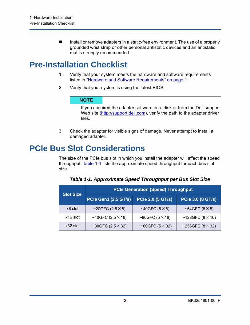
PCIe Bus Slot ConsiderationsThe size of the PCIe bus slot in which you install the adapter will affect the speed throughput. Table 1-1 lists the approximate speed throughput for each bus slot size.
NOTE
If you acquired the adapter software on a disk or from the Dell support Web site (http://support.dell.com), verify the path to the adapter driver files.
Table 1-1. Approximate Speed Throughput per Bus Slot Size
Slot SizePCIe Generation (Speed) Throughput
PCIe Gen1 (2.5 GT/s) PCIe 2.0 (5 GT/s) PCIe 3.0 (8 GT/s)
x8 slot ~20GFC (2.58) ~40GFC (58) ~64GFC (88)
x16 slot ~40GFC (2.516) ~80GFC (516) ~128GFC (816)
x32 slot ~80GFC (2.532) ~160GFC (532) ~256GFC (832)
1–Hardware InstallationInstalling the Adapter
3 BK3254601-00 F
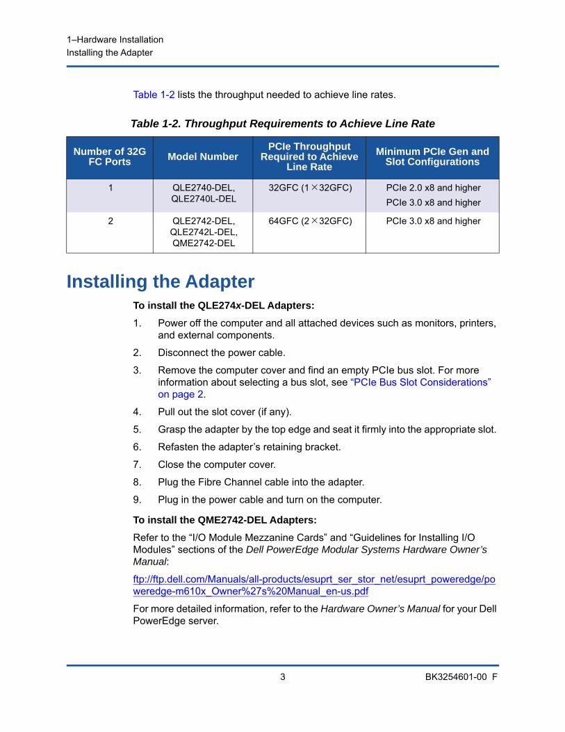
Table 1-2 lists the throughput needed to achieve line rates.
Installing the AdapterTo install the QLE274x-DEL Adapters:
1. Power off the computer and all attached devices such as monitors, printers, and external components.
2. Disconnect the power cable.
3. Remove the computer cover and find an empty PCIe bus slot. For more information about selecting a bus slot, see “PCIe Bus Slot Considerations” on page 2.
4. Pull out the slot cover (if any).
5. Grasp the adapter by the top edge and seat it firmly into the appropriate slot.
6. Refasten the adapter’s retaining bracket.
7. Close the computer cover.
8. Plug the Fibre Channel cable into the adapter.
9. Plug in the power cable and turn on the computer.
To install the QME2742-DEL Adapters:
Refer to the “I/O Module Mezzanine Cards” and “Guidelines for Installing I/O Modules” sections of the Dell PowerEdge Modular Systems Hardware Owner’s Manual:
ftp://ftp.dell.com/Manuals/all-products/esuprt_ser_stor_net/esuprt_poweredge/poweredge-m610x_Owner%27s%20Manual_en-us.pdf
For more detailed information, refer to the Hardware Owner’s Manual for your Dell PowerEdge server.
Table 1-2. Throughput Requirements to Achieve Line Rate
Number of 32G FC Ports Model Number
PCIe Throughput Required to Achieve
Line Rate
Minimum PCIe Gen and Slot Configurations
1 QLE2740-DEL, QLE2740L-DEL
32GFC (132GFC) PCIe 2.0 x8 and higherPCIe 3.0 x8 and higher
2 QLE2742-DEL, QLE2742L-DEL, QME2742-DEL
64GFC (232GFC) PCIe 3.0 x8 and higher

1–Hardware InstallationConnecting to the SAN
4 BK3254601-00 F
Connecting to the SANTo connect the QLE274x-DEL Adapters to the SAN, refer to the Hardware Owner’s Manual for your Dell PowerEdge server.
To connect the QME2742-DEL mezzanine adapter to the SAN, refer to the “Guidelines for Installing I/O Modules” section of the Dell PowerEdge Modular Systems Hardware Owner’s Manual:
ftp://ftp.dell.com/Manuals/all-products/esuprt_ser_stor_net/esuprt_poweredge/poweredge-m610x_Owner%27s%20Manual_en-us.pdf
5 BK3254601-00 F
2 Driver Installation and Configuration
This chapter provides the following information about the drivers included with the adapters:
“Windows Driver Installation and Configuration” on page 5
“Linux Driver Installation and Configuration” on page 12
“VMware Driver Installation and Configuration” on page 16
Windows Driver Installation and ConfigurationYou can run a software or driver Dell Update Package (DUP) in two ways:
Running the Dell Update Package in the GUI
Running the Dell Update Package from the Command Line
NOTE
If you need to update the Flash memory of multiple adapters simultaneously: For QConvergeConsole GUI, refer to the “Update the Flash Using the
Flash Update Wizard” topic in the QConvergeConsole Help. For QConvergeConsole CLI, issue the -flashsupport command to
update the Flash memory for all cards supported by the specified file. For example:qaucli -pr nic -flashsupport -i ALL -a p3p11179.bin
NOTE
When you disable the firmware (for example, during a firmware dump or during a firmware update) in Windows or Linux with a QConvergeConsole agent, multiple application messages are generated. These messages are generated because the application cannot communicate with the adapter while the firmware is disabled. After the firmware is re-enabled, the errors will go away.
2–Driver Installation and ConfigurationWindows Driver Installation and Configuration
6 BK3254601-00 F
Running the Dell Update Package in the GUIBefore you begin, refer to the Dell Update Packages Version xx.xx.xxx User’s Guide, “Prerequisites and Features for Systems Running Windows” section.
To run the DUP in the GUI:
1. Double-click the icon representing the DUP file.
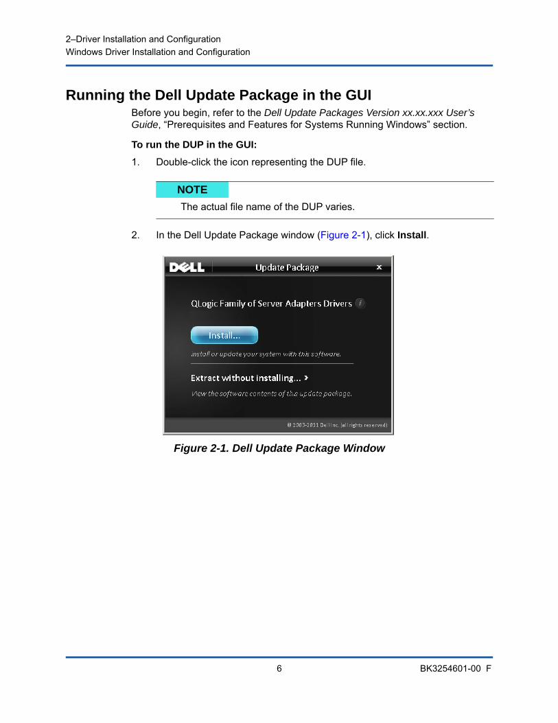
2. In the Dell Update Package window (Figure 2-1), click Install.
Figure 2-1. Dell Update Package Window
NOTE
The actual file name of the DUP varies.
2–Driver Installation and ConfigurationWindows Driver Installation and Configuration
7 BK3254601-00 F
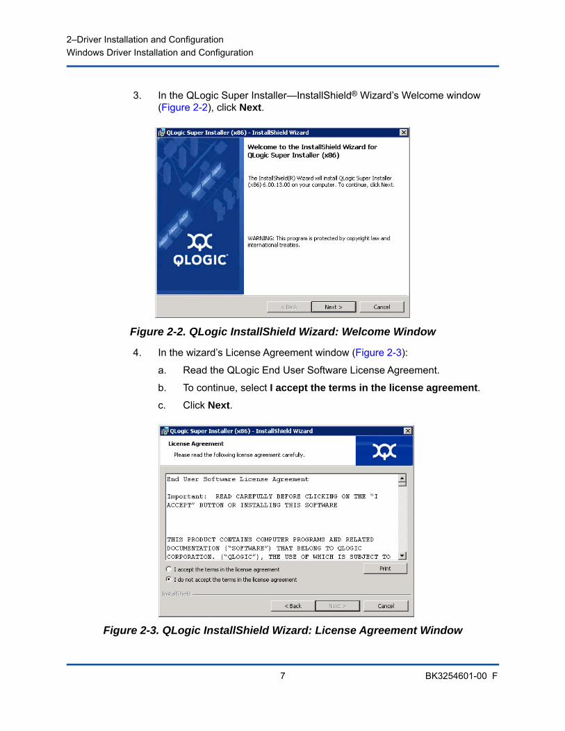
3. In the QLogic Super Installer—InstallShield® Wizard’s Welcome window (Figure 2-2), click Next.
Figure 2-2. QLogic InstallShield Wizard: Welcome Window
4. In the wizard’s License Agreement window (Figure 2-3):
a. Read the QLogic End User Software License Agreement.
b. To continue, select I accept the terms in the license agreement.
c. Click Next.
Figure 2-3. QLogic InstallShield Wizard: License Agreement Window
2–Driver Installation and ConfigurationWindows Driver Installation and Configuration
8 BK3254601-00 F
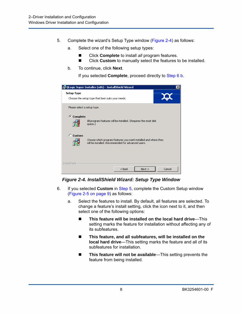
5. Complete the wizard’s Setup Type window (Figure 2-4) as follows:
a. Select one of the following setup types:
Click Complete to install all program features. Click Custom to manually select the features to be installed.
b. To continue, click Next.
If you selected Complete, proceed directly to Step 6 b.
Figure 2-4. InstallShield Wizard: Setup Type Window
6. If you selected Custom in Step 5, complete the Custom Setup window (Figure 2-5 on page 9) as follows:
a. Select the features to install. By default, all features are selected. To change a feature’s install setting, click the icon next to it, and then select one of the following options:
This feature will be installed on the local hard drive—This setting marks the feature for installation without affecting any of its subfeatures.
This feature, and all subfeatures, will be installed on the local hard drive—This setting marks the feature and all of its subfeatures for installation.
This feature will not be available—This setting prevents the feature from being installed.
2–Driver Installation and ConfigurationWindows Driver Installation and Configuration
9 BK3254601-00 F
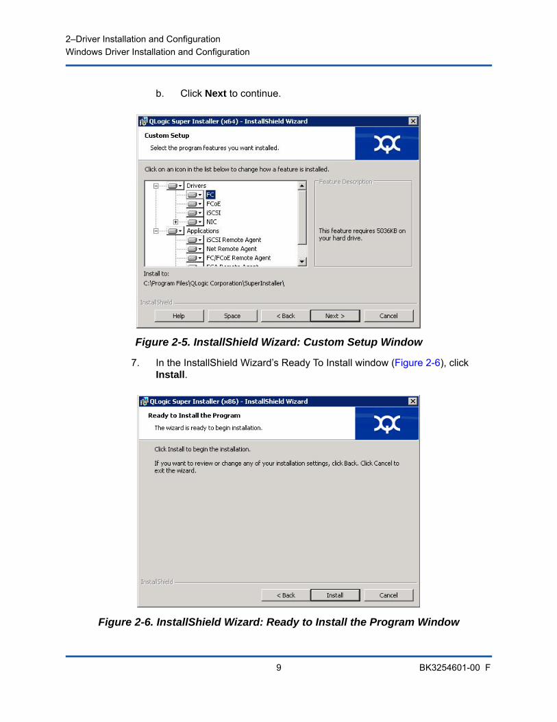
b. Click Next to continue.
Figure 2-5. InstallShield Wizard: Custom Setup Window
7. In the InstallShield Wizard’s Ready To Install window (Figure 2-6), click Install.
Figure 2-6. InstallShield Wizard: Ready to Install the Program Window
2–Driver Installation and ConfigurationWindows Driver Installation and Configuration
10 BK3254601-00 F
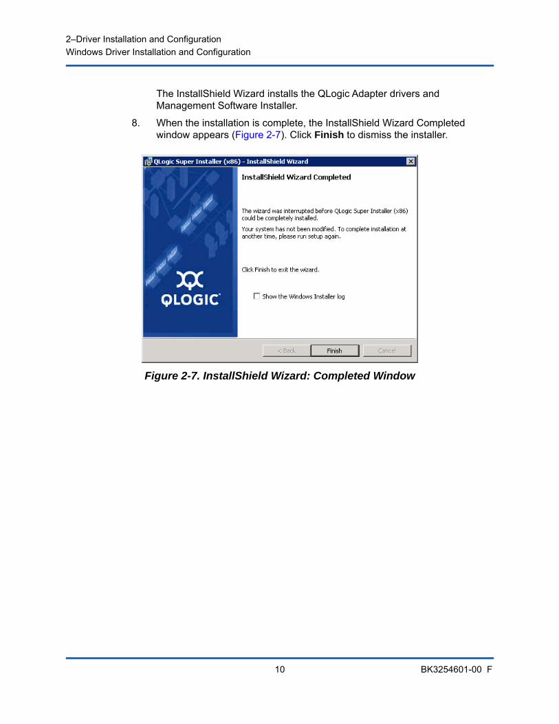
The InstallShield Wizard installs the QLogic Adapter drivers and Management Software Installer.
8. When the installation is complete, the InstallShield Wizard Completed window appears (Figure 2-7). Click Finish to dismiss the installer.
Figure 2-7. InstallShield Wizard: Completed Window

2–Driver Installation and ConfigurationWindows Driver Installation and Configuration
11 BK3254601-00 F
9. In the Dell Update Package (DUP) window (Figure 2-8), “Complete” indicates successful installation.
(Optional) To open the log file, click View Log. The log file shows the progress of the DUP installation, any previous installed versions, any error messages, and other information about the installation.
To close the Update Package window, click OK.
Figure 2-8. Dell Update Package Window
Running the Dell Update Package from the Command LineFor a list of the CLI options for systems running Windows, a description of each option, and the command syntax, refer to the Dell Update Packages Version xx.xx.xxx User’s Guide, “Windows CLI Options” section.
Running the DUP from the command line, with no options specified, results in the same behavior as double-clicking the icon representing the DUP.
To run the DUP from the command line:
C:\><DUP_file_name>.EXE
The following shows the syntax for specifying options to customize the Dell update package installation behavior:
<DUP_file_name>.exe [/<option1>[=<value1>]] [/<option2>[=<value2>]]...
To display the GUI for guided installation, update, or extraction, use no options.
NOTE
The actual file name of the DUP varies.
2–Driver Installation and ConfigurationLinux Driver Installation and Configuration
12 BK3254601-00 F
ExamplesTo update the system silently:
<DUP_file_name>.exe /s
To extract the update contents to the C:\mydir\ directory:
<DUP_file_name>.exe /s /e=C:\mydir
To extract the driver components to the C:\mydir\ directory:
<DUP_file_name>.exe /s /drivers=C:\mydir
To install only the driver components:
<DUP_file_name>.exe /s /driveronly
To change from the default log location to C:\my path with spaces\log.txt:
<DUP_file_name>.exe /l="C:\my path with spaces\log.txt"
Linux Driver Installation and ConfigurationThis section provides the following procedures for installing drivers on a Linux system:
Installation Overview
Installing the Linux Fibre Channel Driver
2–Driver Installation and ConfigurationLinux Driver Installation and Configuration
13 BK3254601-00 F
Installation OverviewTo install and configure the adapter drivers on a Linux system, refer to the driver release notes, readme, and installation instructions included in the package.
Installing the Linux Fibre Channel DriverThis section provides procedures for installing the Linux Fibre Channel driver for the following operating systems:
Building the Driver for 7.x Building the Driver for SLES 12 and SLES 15
Building the Driver for 7.x1. From the directory that contains the source driver file,
qla2xxx-src-vx.xx.xx.xx.06.x-k.tar.gz, issue the appropriate commands for your Linux version.
# tar -xzvf qla2xxx-src-vx.xx.xx.xx.07.x-k.tar.gz
# cd qla2xxx-src-vx.xx.xx.xx.07.x-k
2. Build and install the driver modules from the source code by executing the build.sh script as follows:
# ./extras/build.sh install
The build.sh script does the following:
Builds the driver .ko files.
Copies the .ko files to the appropriate /lib/modules/<kernel version>/extra/qlgc-qla2xxx directory.
NOTE
To install the Red Hat Package Manager (RPM), issue the following command as a root user:
# rpm -Uvh <rpm name>
For example:# rpm -Uvh qla2xxx-kmp-default-<driver-version_kernel-version>-<release>.x86_64.rpm
To uninstall the RPM, issue the following command as a root user:# rpm -e <rpm>
For example:# rpm -e qla2xxx-kmp-default-<driver-version_kernel-version>-<release>

2–Driver Installation and ConfigurationLinux Driver Installation and Configuration
14 BK3254601-00 F
Add the appropriate directive in the modprobe.conf (if applicable).
3. (Optional) To manually load the driver, issue the insmod or modprobe command:
To directly load the driver from the local build directory, issue the following insmod commands in order:
# modprobe scsi_tgt.ko (if not already loaded)# modprobe scsi_transport_fc.ko
# insmod qla2xxx.ko
To load the driver using modprobe, issue the following command:
# modprobe -v qla2xxx
To unload the driver using modprobe, issue the following command:
# modprobe -r qla2xxx
4. (Optional) To automatically load the driver each time the system boots, rebuild the RAM disk to include the driver as follows:
a. Create a backup copy of the RAMDISK image by issuing the following commands:
# cd /boot
# cp initramfs-[kernel version].img initramfs-[kernel version].img.bak
b. Create the new RAMDISK by issuing the following command:
# dracut -f
c. To load the driver, reboot the host.
Building the Driver for SLES 12 and SLES 151. From the directory that contains the source driver file,
qla2xxx-src-vx.xx.xx.xx.xx.x-k.tgz, issue the following commands:
# tar -xzvf qla2xxx-src-vx.xx.xx.xx.xx.x-k.tgz# cd qla2xxx-x.xx.xx.xx.xx.xx-k4
Where x.xx.xx.xx.xx.xx is the applicable version number.
NOTE
You can optionally complete either or both Step 3 and Step 4 of this procedure.

2–Driver Installation and ConfigurationLinux Driver Installation and Configuration
15 BK3254601-00 F
2. Build and install the driver modules from the source code by executing the build.sh script as follows:
# ./extras/build.sh install
The build.s h script does the following:
Builds the driver .ko files.
Copies the .ko files to the appropriate /lib/modules/3.x.../updates directory.
Adds the appropriate directive in the modprobe.conf file (if applicable).
3. (Optional) Manually load the driver for Linux.
Edit the /etc/modprobe.d/unsupported_modules file to make the following change:
allow_unsupported_modules 1 (replace 0 with 1)
To load the driver using modprobe, issue the following command:
# modprobe -v qla2xxx
To unload the driver using modprobe, issue the following command:
# modprobe -r qla2xxx
4. (Optional) To automatically load the driver each time the system boots, rebuild the RAM disk to include the driver as follows:
a. Create a backup copy of the RAMDISK image by issuing the following commands:
# cd /boot
# cp initramfs-[kernel version].img initramfs-[kernel version].img.bak
b. Create the new RAMDISK by issuing the following command:
# dracut -f
5. To load the driver, reboot the host.
NOTE
You can optionally complete either or both Step 3 and Step 4 of this procedure.
2–Driver Installation and ConfigurationVMware Driver Installation and Configuration
16 BK3254601-00 F
VMware Driver Installation and ConfigurationThis section provides the following procedures for installing drivers on a VMware system:
Installation Overview
Installing the ESXi 6.7, 6.5, and 6.0 U2 Fibre Channel Driver
Installing QConvergeConsole VMware vCenter Server Plug-in
Installing
Configuring VM-ID
Installation OverviewTo install and configure the adapter drivers on a VMware system, refer to the driver release notes and readme files included in the package.
Installing the ESXi 6.7, 6.5, and 6.0 U2 Fibre Channel DriverThe operating system manages and controls the driver installation process. To install the ESXi driver, follow the steps in this section.
This section provides procedures for the following:
“Updating an Existing Driver or Installing a New Driver for an Existing ESXi 6.7, 6.5 or 6.0 U2/U3 Installation with esxcli” on page 17
“Verifying the Version of the Installed Driver” on page 17
NOTE
This section provides the most common ways of installing and upgrading the driver. For other installation procedures, consult the operating system manuals and the driver readme file.
2–Driver Installation and ConfigurationVMware Driver Installation and Configuration
17 BK3254601-00 F
Updating an Existing Driver or Installing a New Driver for an Existing ESXi 6.7, 6.5 or 6.0 U2/U3 Installation with esxcli
To use the driver bundle <offline-bundle>.zip):
1. Copy the driver bundle (<offline-bundle>.zip) to this ESXi host.
2. Install the driver bundle (<offline-bundle>.zip) as follows:
a. To create a temporary directory, issue the following commands:
mkdir /install
cd /install
b. Unzip the driver bundle in the temporary directory:
/install : unzip <offline-bundle>.zip
c. Issue the following command:
esxcli software vib install -n qlnativefc -d /install
To use the driver VIB:
1. Copy the driver VIB to this ESXi host by issuing the following command:
qlnativefc-<driver-version>-1OEM.<esx-build>.x86_64.vib
2. Install the driver VIB using the following esxcli commands:
a. To make a temporary directory, issue the following commands:
mkdir /install
cd /install
b. Issue the following command:
esxcli software vib install -v /install/<driver-vib>
Verifying the Version of the Installed DriverTo verify the installed package in the system, issue the following command:
esxcli software vib list | grep qlnativefc
The driver version is embedded in the VIB version.
For example, the output looks like the following:
# esxcli software vib list | grep qlnativefc
qlnativefc 2.1.50.0-1OEM.600.0.0.2768847 QLogic VMwareCertified 2017-01-19
2–Driver Installation and ConfigurationVMware Driver Installation and Configuration
18 BK3254601-00 F
Installing QConvergeConsole VMware vCenter Server Plug-inTo use QConvergeConsole VMware vCenter Server Plug-in, install the following software in this order:
1. QConvergeConsole VMware vCenter Server Plug-in on the vCenter Server
2. QLogic Adapter CIM Provider on the ESXi server
The following sections explain how to install and uninstall the required software:
“Installation Package Contents” on page 18
“Installing QConvergeConsole VMware vCenter Server Plug-in” on page 19
“Plug-in Unregistration from a Manual Install” on page 23
“Uninstalling the QConvergeConsole VMware vCenter Server Plug-in” on page 24
“Installing the QLogic Adapter CIM Provider” on page 24
“Uninstalling the QLogic Adapter CIM Provider” on page 28
For information on installing the Plug-in, refer to “Installing QConvergeConsole VMware vCenter Server Plug-in” on page 19.
Installation Package ContentsThe latest version of the QLogic Adapter CIM Provider and QConvergeConsole VMware vCenter Server Plug-in package contains the files needed to install both the Plug-in and the CIM Provider. Required files include the following (where x_x_x is the version number):
QLogic_Adapter_VI_Plugin_x_x_x.exe—This file is the QConvergeConsole VMware vCenter Server Plug-in installation package.
qlogic_adapter_provider_vmware_esx55_60-x.x.x—This file contains the QLogic Adapter CIM Provider installation package for ESXi 6.0 U2/U3, where x.x.x is the version of the CIM Provider.
qlogic_adapter_provider_vmware_esx65-x.x.x—This file contains the QLogic Adapter CIM Provider installation package for ESXi 6.5 and ESXi 6.5 U1, where x.x.x is the version of the CIM Provider.
readme.txt—This file is the Read Me document that covers hardware and software requirements, operating system support, supported features, installation and removal instructions, known issues and workarounds, and support contact information.
release_notes.txt—This file is the Release Notes document that lists changes, fixes, known issues, and release details.

2–Driver Installation and ConfigurationVMware Driver Installation and Configuration
19 BK3254601-00 F
For detailed information on installing the QConvergeConsole VMware vCenter Server Plug-in, refer to “Installing QConvergeConsole VMware vCenter Server Plug-in” on page 19.
For detailed information on installing the CIM Provider, refer to “Installing the QLogic Adapter CIM Provider” on page 24.
Installing QConvergeConsole VMware vCenter Server Plug-in
To install the QConvergeConsole VMware vCenter Server Plug-in:
1. Download the QLogic_Adapter_VI_Plugin_x_x_x.exe file (where x_x_x is the version number).
2. Start the installation either by double-clicking the .exe file, by typing the name of the .exe file in a Run window, or by clicking Browse and locating the .exe file.
The InstallAnywhere wizard opens, as shown in Figure 2-9.
Figure 2-9. InstallAnywhere Initial Window
2–Driver Installation and ConfigurationVMware Driver Installation and Configuration
20 BK3254601-00 F
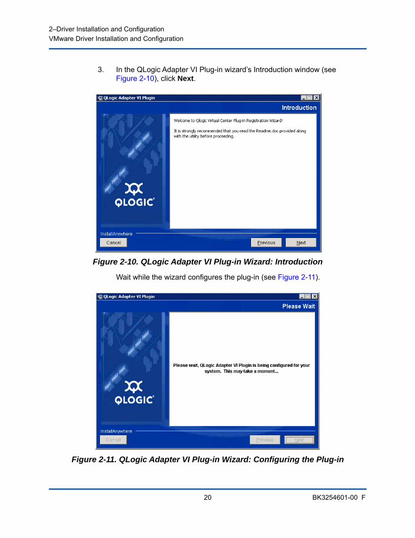
3. In the QLogic Adapter VI Plug-in wizard’s Introduction window (see Figure 2-10), click Next.
Figure 2-10. QLogic Adapter VI Plug-in Wizard: Introduction
Wait while the wizard configures the plug-in (see Figure 2-11).
Figure 2-11. QLogic Adapter VI Plug-in Wizard: Configuring the Plug-in
2–Driver Installation and ConfigurationVMware Driver Installation and Configuration
21 BK3254601-00 F
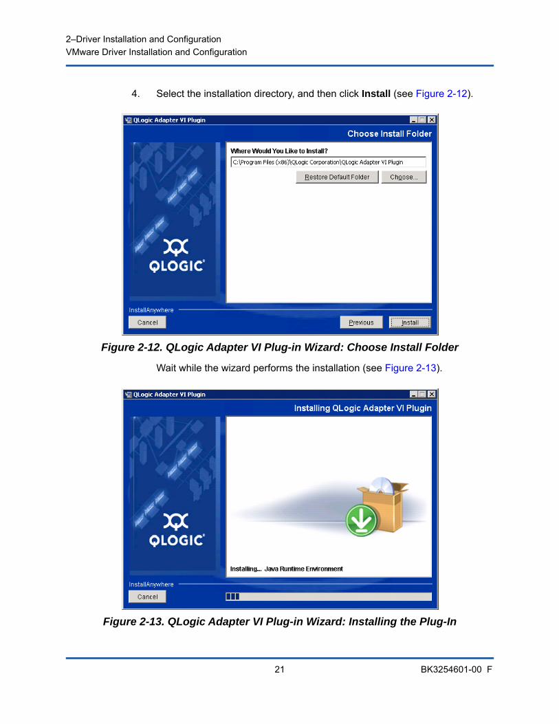
4. Select the installation directory, and then click Install (see Figure 2-12).
Figure 2-12. QLogic Adapter VI Plug-in Wizard: Choose Install Folder
Wait while the wizard performs the installation (see Figure 2-13).
Figure 2-13. QLogic Adapter VI Plug-in Wizard: Installing the Plug-In
2–Driver Installation and ConfigurationVMware Driver Installation and Configuration
22 BK3254601-00 F
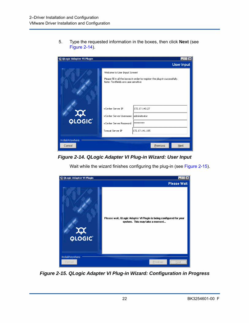
5. Type the requested information in the boxes, then click Next (see Figure 2-14).
Figure 2-14. QLogic Adapter VI Plug-in Wizard: User Input
Wait while the wizard finishes configuring the plug-in (see Figure 2-15).
Figure 2-15. QLogic Adapter VI Plug-in Wizard: Configuration in Progress
2–Driver Installation and ConfigurationVMware Driver Installation and Configuration
23 BK3254601-00 F
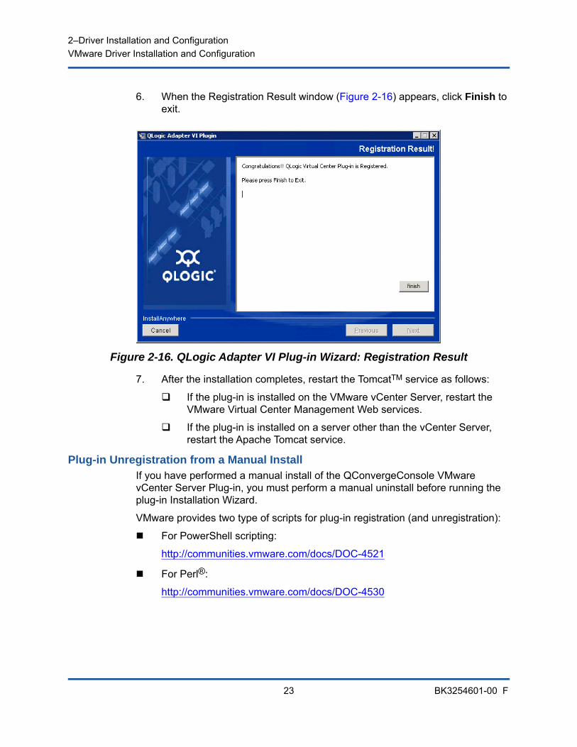
6. When the Registration Result window (Figure 2-16) appears, click Finish to exit.
Figure 2-16. QLogic Adapter VI Plug-in Wizard: Registration Result
7. After the installation completes, restart the TomcatTM service as follows:
If the plug-in is installed on the VMware vCenter Server, restart the VMware Virtual Center Management Web services.
If the plug-in is installed on a server other than the vCenter Server, restart the Apache Tomcat service.
Plug-in Unregistration from a Manual InstallIf you have performed a manual install of the QConvergeConsole VMware vCenter Server Plug-in, you must perform a manual uninstall before running the plug-in Installation Wizard.
VMware provides two type of scripts for plug-in registration (and unregistration):
For PowerShell scripting:
http://communities.vmware.com/docs/DOC-4521
For Perl®:
http://communities.vmware.com/docs/DOC-4530
2–Driver Installation and ConfigurationVMware Driver Installation and Configuration
24 BK3254601-00 F
Before you can use the script, you must download the appropriate VI SDK from VMware:
For Perl VI SDK, download vSphere SDK for Perl:
http://www.vmware.com/support/developer/viperltoolkit/
For PowerShell, download vSphere PowerCLI:
http://communities.vmware.com/community/vmtn/vsphere/automationtools/powercli
After downloading and installing the SDK and the registration script, follow the VMware instructions to unregister the plug-in. For example, the Perl unregister command is:
perl registerPlugin.pl --server="127.0.0.1" -username="administrator" --password="password" --key="com.qlogic.QLogicAdapterVIPlugIn" --action="remove"
To log into the vCenter Server, replace administrator and password with the correct information.
Uninstalling the QConvergeConsole VMware vCenter Server Plug-in
To remove the QConvergeConsole VMware vCenter Server Plug-in:
1. In the Windows Control Panel, select Programs and Features.
2. In the Add or Remove Programs dialog box, select the QConvergeConsole VMware vCenter Server Plug-in, and then click Change/Remove.
3. To remove the plug-in, follow the instructions in the QConvergeConsole VMware vCenter Server Plug-in installer.
Installing the QLogic Adapter CIM ProviderThis section describes how to install, start, and remove the QLogic Adapter CIM Provider for VMware ESXi. Because there are multiple zip packages, ensure that you pick the zip package that matches your environment: ESXi 6.7, 6.5 and ESXi 6.0 U2.
NOTE
The QLogic Adapter CIM Provider for VMware ESXi was generated as a VIB file. A VIB contains the complete set of files and binaries required to install the provider on VMware ESXi. The file offline-bundle.zip contains the VIB and the necessary metadata to install the provider on VMware ESXi.

2–Driver Installation and ConfigurationVMware Driver Installation and Configuration
25 BK3254601-00 F
Initial Installation MethodsInitial installation methods for the CIM Provider include the following:
Online. Refer to “Installing the CIM Provider on an ESXi 6.7, 6.5, or 6.0 U2/U3 Host” on page 25.
Offline. Refer to “Existing ESXi Installation Using VMware Update Manager” on page 26.
Remote. Refer to “Remote Installation of the CIM Provider on an ESXi Host” on page 26.
Installing the CIM Provider on an ESXi 6.7, 6.5, or 6.0 U2/U3 Host1. For an ESXi 6.5/6.7 host, do the following; otherwise proceed to Step 2.
a. Turn off the firewall on the ESXi 6.5/ESXi 6.7 host by issuing the following command:
esxcli network firewall set --enabled false
b. Reboot the ESXi 6.5/6.7 host.
c. On some platforms, FC adapters are not discovered from ESXi 6.7 through vCenter. If this happens, restart the CIMON by issuing the following commands:
/etc/init.d/sfcbd-watchdog stop
/etc/init.d/sfcbd-watchdog restart
2. Copy the following file to the root directory (/) of the ESXi system:
QLGC-ESX-5.5.0-qlogic-adapter-provider-x.x.xx.xxxxxxx-offline_bundle-xxxxxxx.zip
3. Issue the esxcli commands as follows:
# cd /
# esxcli software acceptance set --level=CommunitySupported
# esxcli software vib install -d
file://<offline bundle>.zip --maintenance-mode
4. Reboot the system as required.
NOTE
For an ESXi 6.0 U2/U3 host, select the .zip file for that version instead.
2–Driver Installation and ConfigurationVMware Driver Installation and Configuration
26 BK3254601-00 F
Existing ESXi Installation Using VMware Update ManagerAn existing ESXi host has asynchronous drivers installed using VMware Update Manager (VUM). For more information, see “Using vSphere ESXi Image Builder CLI” in the vSphere Installation and Setup Guide at:
http://www.vmware.com/support/pubs/vsphere-esxi-vcenter-server-pubs.html
To install the asynchronous drivers:
1. Extract the contents of the asynchronous driver zip file.
2. Identify the offline-bundle.zip file or files.
3. From vCenter Server, go to Home, and then select Update Manager.
4. Click the Patch Repository tab.
5. Click the Import Patches link at the top right of the window.
6. Click Finish.
The asynchronous driver is now added to the patch repository.
7. Create a baseline and remediate the ESXi host. For more information, refer to Installing and Administering VMware vSphere Update Manager:
http://www.vmware.com/support/pubs/vum_pubs.html.
Remote Installation of the CIM Provider on an ESXi Host
1. Copy the offline-bundle.zip file to any location on the host where either the vSphere CLI package is installed or vSphere Management Assistant (vMA) is hosted.
2. Navigate to the location of the offline-bundle.zip file.
3. To install the offline bundle, issue the vihostupdate command as follows:
# vihostupdate.pl <conn_options> --install --bundle offline-bundle.zip --nosigcheck
NOTE
Before performing this procedure, ensure that the remote ESXi system is in Maintenance Mode. To do so using vSphere Client, select Inventory, select Host, and then select Enter Maintenance Mode.

2–Driver Installation and ConfigurationVMware Driver Installation and Configuration
27 BK3254601-00 F
4. Follow the on-screen instructions to complete the installation. You might need to reboot the ESXi system.
Subsequent Update InstallationTo update the QLogic Adapter CIM Provider after a prior VIB installation, follow the instructions in “Uninstalling the QLogic Adapter CIM Provider” on page 28 to remove the existing VIB. After completing the VIB removal, use the same steps in “Initial Installation Methods” on page 25 to install the new VIB.
Starting the QLogic Adapter CIM Provider After a system startup, the SFCB (Small-Footprint CIM Broker) CIMOM (CIM object manager) in the ESXi system should start automatically and load the QLogic Adapter CIM Provider, when necessary.
If the CIM Provider does not start automatically, you can manually stop, start, or restart the SFCB CIMOM by issuing the following commands.
To stop the SFCB CIMOM and the QLogic Adapter CIM Provider:
# /etc/init.d/sfcbd-watchdog stop
To start the SFCB CIMOM and the QLogic Adapter CIM Provider:
# /etc/init.d/sfcbd-watchdog start
To restart the SFCB CIMOM and the QLogic Adapter CIM Provider:
# /etc/init.d/sfcbd-watchdog restart
After starting the SFCB CIMOM, use a CIM client utility to query the QLogic Adapter CIM Provider for information.
NOTE
For more details on the vihostupdate command, see the vSphere Command-Line Interface Installation and Reference Guide at:http://www.vmware.com/pdf/vsphere4/r40/vsp_40_vcli.pdf

2–Driver Installation and ConfigurationVMware Driver Installation and Configuration
28 BK3254601-00 F
Uninstalling the QLogic Adapter CIM ProviderYou can uninstall the QLogic Adapter CIM Provider for your version of VMware. For information about removing the QLogic Adapter CIM Provider through a remote host, see the QLogic Adapter CIM Provider and vCenter Plug-in for VMware ESX/ESXi Readme file.
To uninstall the CIM Provider from an ESXi 5.x host:
1. To view the VIB list, issue the following command:
# esxcli software vib list
2. To remove the QLogic Adapter CIM Provider, issue the following command:
# esxcli software vib remove --vibname qlogic-adapter-provider --maintenance-mode –f
To uninstall the CIM Provider from a remote host:
1. From a console on the host where the vSphere CLI package is installed or vMA is hosted, query and find the Bulletin ID of the existing provider:
# vihostupdate.pl <conn_options> --query
2. Remove the existing VIB by issuing the following command:
# vihostupdate.pl <conn_options> --remove --bulletin <bulletinID>
NOTE
Before performing this procedure, make sure that the ESXi system is in Maintenance Mode. To do so using the vSphere Client, select Inventory, select Host, and then select Enter Maintenance Mode.
NOTE
For more details on vihostupdate, see the vSphere Command-Line Interface Installation and Reference Guide, located here:http://www.vmware.com/pdf/vsphere4/r40/vsp_40_vcli.pdf

2–Driver Installation and ConfigurationVMware Driver Installation and Configuration
29 BK3254601-00 F
Installing 1. Gather the information necessary for the installation, including:
IP address of the vCenter Server
vCenter Server credentials (user name and password)
Where to host the QConvergeConsole VMware vSphere Web Client Plug-in (on vCenter Server or other server)
If you are hosting the QConvergeConsole VMware vSphere Web Client Plug-in on a non-vCenter Server, make sure the server has Tomcat running as a service and have the IP address of the Tomcat instance ready. Also, make sure the Tomcat CATALINA_HOME environment variable is set to the appropriate directory.
2. Run the installer on the server providing the Tomcat service. Provide the information requested by the installer.
On Windows, double-click the installer and follow the instructions on the GUI provided.
On Linux:
a. Make sure the user is the root user (or has root privileges).
b. Create the installer executable if one does not already exist. Choose the installer for your system (32-bit or 64-bit), and then issue the following command:
chmod +x <installer>
Where <installer> is the file name of the installer.
c. Run the installer by issuing the following command:
./<installer>
Where <installer> is the file name of the installer.
d. Follow the instructions provided by the installer.
3. Restart the Tomcat service.
If the QConvergeConsole VMware vCenter Server Plug-in is being hosted on the vCenter Server, you must restart the VMware Virtual Center Management Web services:
In Windows, go to the Administrative Tools menu, select Services, and then restart VMware Virtual Center Management Web services.
On the vCenter Server Appliance (Linux), issue the following command:
/etc/init.d/vmware-vpxd tomcat-restart
2–Driver Installation and ConfigurationVMware Driver Installation and Configuration
30 BK3254601-00 F
4. Restart any vSphere Web Client sessions.
If you are updating a previous version of the QConvergeConsole VMware vCenter Server Plug-in, restart the vSphere Web Client services as follows:
In Windows, go to the Administrative Tools menu, select Services, and then restart VMware vSphere Web Client.
On the vCenter Server Appliance (Linux), issue the following command:
/etc/init.d/vsphere-client restart
Uninstalling the QConvergeConsole VMware vCenter Server Plug-inTo uninstall the QConvergeConsole VMware vCenter Server Plug-in, refer to the procedure for Windows or Linux:
Windows. Uninstall the QConvergeConsole VMware vCenter Server Plug-in on Windows using the Windows Control Panel Uninstall Program window. Follow the uninstaller user interface to remove the plug-in.
Linux. Uninstall the QConvergeConsole VMware vCenter Server Plug-in on Linux by issuing the following command at a command prompt:
/opt/qlogic/QLogic\ Adapter\ Web\ Client\ Plugin/Uninstall_QLogic\ Adapter\ Web\ Client\ Plugin/Uninstall\ QLogic\ Adapter\ Web\ Client\ Plugin
Follow the prompts (user interface or console commands) to uninstall the plug-in by the root user.
2–Driver Installation and ConfigurationVMware Driver Installation and Configuration
31 BK3254601-00 F
Configuring VM-IDVM storage I/O activity automatically generates VM-ID tagging in FC frames. VM-ID tags I/O frames with an ID that identifies the virtual machine that sent or received them. This ID allows management applications to monitor traffic flows down to the virtual machine level. VM-ID is disabled by default and requires a switch running FOS version 8.1.0a or later on Brocade switches. For detailed VM-ID information, see the documentation for your switch.
To enable VM-ID (and disable QoS), type the following command and then reboot the system:
$ esxcfg-module -s "ql2xvmidsupport=1, ql2xfabricpriorityqos=0" qlnativefc
To disable VM-ID, type the following command, and then reboot the system:
$ esxcfg-module -s "ql2xvmidsupport=0" qlnativefc
For details about configuring VM-ID, see the QLogic Fibre Channel and Converged Network Adapters for VMware ESXi 5.5 and 6.x User’s Guide (SN0154529-00).
32 BK3254601-00 F
3 Fibre Channel Configuration
This chapter provides the following information about configuring Fibre Channel:
“Updating the Dell Firmware” on page 33
“Using Fast!UTIL for Custom Configuration” on page 37
“Setting Fibre Channel Adapter Parameters” on page 43
“Configuring Target Persistent Binding” on page 44
“Configuring Boot Devices” on page 46
“Configuring Virtual Ports (NPIV)” on page 47
“Configuring Fibre Channel Driver Parameters” on page 54
“Configuring Selective LUNs” on page 55
“Configuring OoOFR” on page 56
“Configuring the UEFI Driver” on page 57
“Setting an FA-PWWN” on page 64
“Configuring and Verifying FA-BLD” on page 70
“Using a Fabric-Assigned Boot LUN” on page 76
“Running Diagnostics—Fibre Channel Ping and Trace Route” on page 78
“Configuring CS_CTL QoS” on page 83
“Configuring End-to-End CS_CTL QoS” on page 87
“Configuring FDMI” on page 92
“Enabling QLogic Forward Error Correction” on page 96
“Running Extended Link Service Commands” on page 98
NOTE
For information on configuring the Fibre Channel Adapter using VMware vCenter Server, refer to the User’s Guide—QConvergeConsole Plug-ins for VMware vSphere (part number SN0054677-00), available at:www.cavium.com, Downloads
3–Fibre Channel ConfigurationUpdating the Dell Firmware
33 BK3254601-00 F
Updating the Dell FirmwareThe firmware Dell Update Package (DUP) is a Flash update utility only; it is not used for adapter configuration. To run the firmware DUP, double-click the executable file. Alternatively, run the firmware DUP from the command line, which supports several command line options.
Running the Firmware Update by Double-ClickingFor additional information, refer to the Dell Update Packages Version xx.xx.xxx User’s Guide, “Using Dell Update Packages” section.
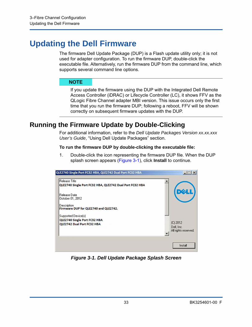
To run the firmware DUP by double-clicking the executable file:
1. Double-click the icon representing the firmware DUP file. When the DUP splash screen appears (Figure 3-1), click Install to continue.
Figure 3-1. Dell Update Package Splash Screen
NOTE
If you update the firmware using the DUP with the Integrated Dell Remote Access Controller (iDRAC) or Lifecycle Controller (LC), it shows FFV as the QLogic Fibre Channel adapter MBI version. This issue occurs only the first time that you run the firmware DUP; following a reboot, FFV will be shown correctly on subsequent firmware updates with the DUP.
3–Fibre Channel ConfigurationUpdating the Dell Firmware
34 BK3254601-00 F
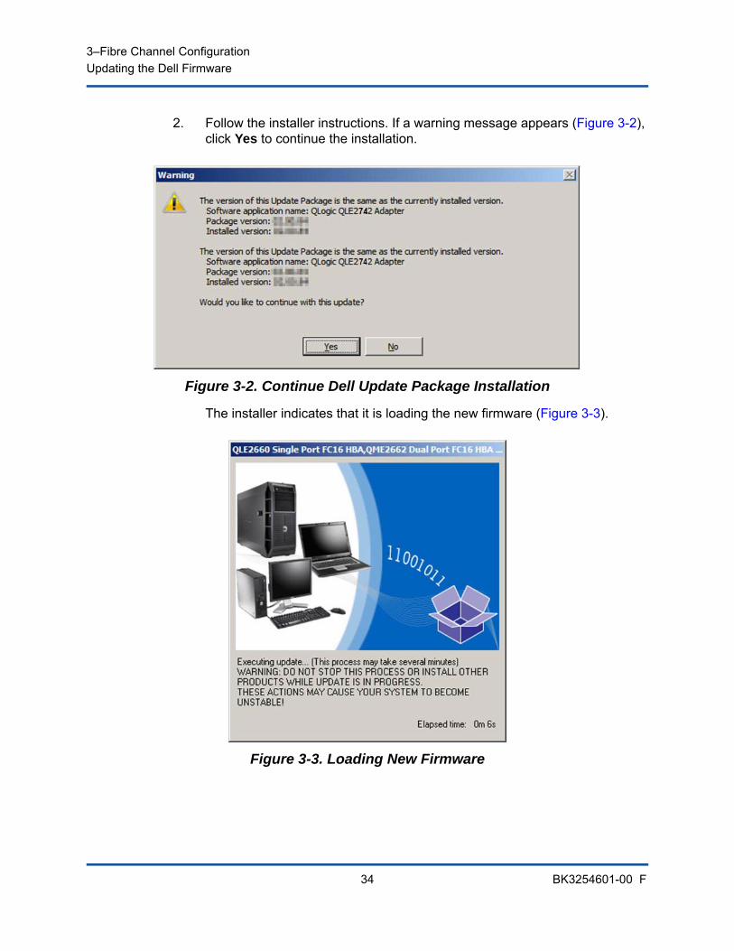
2. Follow the installer instructions. If a warning message appears (Figure 3-2), click Yes to continue the installation.
Figure 3-2. Continue Dell Update Package Installation
The installer indicates that it is loading the new firmware (Figure 3-3).
Figure 3-3. Loading New Firmware
3–Fibre Channel ConfigurationUpdating the Dell Firmware
35 BK3254601-00 F
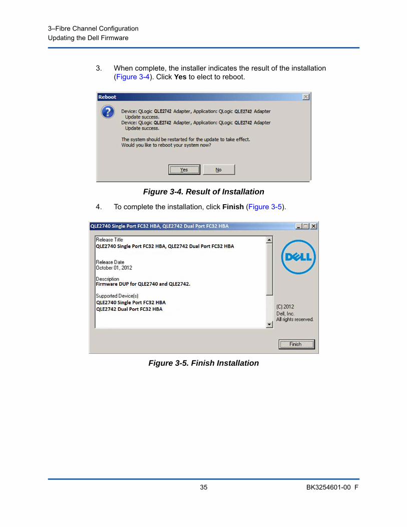
3. When complete, the installer indicates the result of the installation (Figure 3-4). Click Yes to elect to reboot.
Figure 3-4. Result of Installation
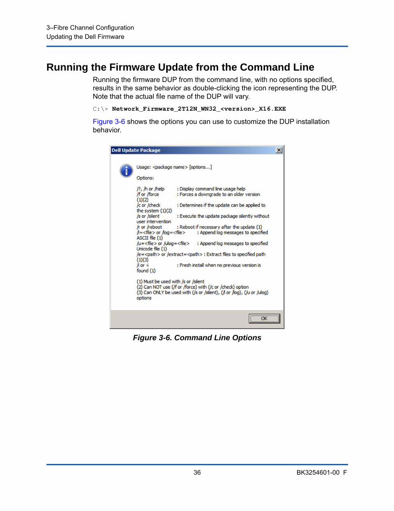
4. To complete the installation, click Finish (Figure 3-5).
Figure 3-5. Finish Installation
3–Fibre Channel ConfigurationUpdating the Dell Firmware
36 BK3254601-00 F
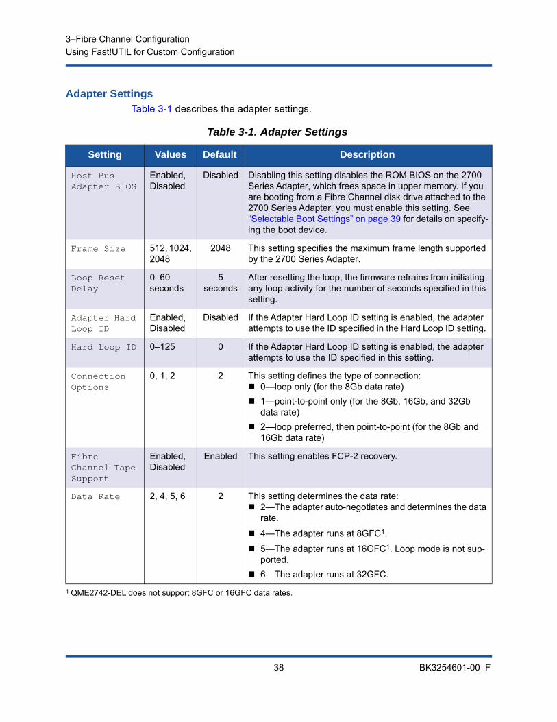
Running the Firmware Update from the Command LineRunning the firmware DUP from the command line, with no options specified, results in the same behavior as double-clicking the icon representing the DUP. Note that the actual file name of the DUP will vary.
C:\> Network_Firmware_2T12N_WN32_<version>_X16.EXE
Figure 3-6 shows the options you can use to customize the DUP installation behavior.
Figure 3-6. Command Line Options
3–Fibre Channel ConfigurationUsing Fast!UTIL for Custom Configuration
37 BK3254601-00 F
Using Fast!UTIL for Custom ConfigurationThis section provides detailed configuration information for advanced users who want to customize the configuration of the adapters and connected devices using Fast!UTIL (the QLogic Fibre Channel Adapter BIOS utility) in a pre-OS environment.
To configure adapters using Fast!UTIL:
1. During the Host Bus Adapter BIOS initialization, press ALT+Q or CTRL+Q. It may take a few seconds for the Fast!UTIL menu to appear.
2. When the Select Host Adapter window appears, select the adapter type.
3. In the Adapter Settings window (see “Adapter Settings” on page 38), configure the adapter settings.
4. A message indicates that the configuration settings have been modified. Select Save changes.
5. To load the new parameters, reboot the system.
The Fast!UTIL Options menu provides the following options:
Configuration Settings Scan Fibre Devices Fibre Disk Utility Loopback Data Test Select Adapter Exit Fast!UTIL
Configuration SettingsThe following sections show and describe the 2700 Series Adapters Configuration Settings menu options in Fast!UTIL:
Adapter Settings
Selectable Boot Settings
Restore Default Settings
Raw NVRAM Data
Advanced Adapter Settings
CAUTION
If the configuration settings are incorrect, your 2700 Series Adapter may not function properly.
3–Fibre Channel ConfigurationUsing Fast!UTIL for Custom Configuration
38 BK3254601-00 F
Adapter SettingsTable 3-1 describes the adapter settings.
Table 3-1. Adapter Settings
Setting Values Default Description
Host Bus Adapter BIOS
Enabled, Disabled
Disabled Disabling this setting disables the ROM BIOS on the 2700 Series Adapter, which frees space in upper memory. If you are booting from a Fibre Channel disk drive attached to the 2700 Series Adapter, you must enable this setting. See “Selectable Boot Settings” on page 39 for details on specify-ing the boot device.
Frame Size 512, 1024, 2048
2048 This setting specifies the maximum frame length supported by the 2700 Series Adapter.
Loop Reset Delay
0–60 seconds
5 seconds
After resetting the loop, the firmware refrains from initiating any loop activity for the number of seconds specified in this setting.
Adapter Hard Loop ID
Enabled, Disabled
Disabled If the Adapter Hard Loop ID setting is enabled, the adapter attempts to use the ID specified in the Hard Loop ID setting.
Hard Loop ID 0–125 0 If the Adapter Hard Loop ID setting is enabled, the adapter attempts to use the ID specified in this setting.
Connection Options
0, 1, 2 2 This setting defines the type of connection: 0—loop only (for the 8Gb data rate) 1—point-to-point only (for the 8Gb, 16Gb, and 32Gb
data rate) 2—loop preferred, then point-to-point (for the 8Gb and
16Gb data rate)
Fibre Channel Tape Support
Enabled, Disabled
Enabled This setting enables FCP-2 recovery.
Data Rate 2, 4, 5, 6 2 This setting determines the data rate: 2—The adapter auto-negotiates and determines the data
rate.
4—The adapter runs at 8GFC1.
5—The adapter runs at 16GFC1. Loop mode is not sup-ported.
6—The adapter runs at 32GFC.
1 QME2742-DEL does not support 8GFC or 16GFC data rates.
3–Fibre Channel ConfigurationUsing Fast!UTIL for Custom Configuration
39 BK3254601-00 F
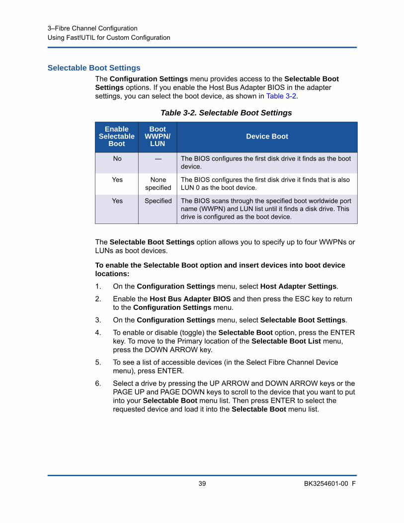
Selectable Boot SettingsThe Configuration Settings menu provides access to the Selectable Boot Settings options. If you enable the Host Bus Adapter BIOS in the adapter settings, you can select the boot device, as shown in Table 3-2.
The Selectable Boot Settings option allows you to specify up to four WWPNs or LUNs as boot devices.
To enable the Selectable Boot option and insert devices into boot device locations:
1. On the Configuration Settings menu, select Host Adapter Settings.
2. Enable the Host Bus Adapter BIOS and then press the ESC key to return to the Configuration Settings menu.
3. On the Configuration Settings menu, select Selectable Boot Settings.
4. To enable or disable (toggle) the Selectable Boot option, press the ENTER key. To move to the Primary location of the Selectable Boot List menu, press the DOWN ARROW key.
5. To see a list of accessible devices (in the Select Fibre Channel Device menu), press ENTER.
6. Select a drive by pressing the UP ARROW and DOWN ARROW keys or the PAGE UP and PAGE DOWN keys to scroll to the device that you want to put into your Selectable Boot menu list. Then press ENTER to select the requested device and load it into the Selectable Boot menu list.
Table 3-2. Selectable Boot Settings
Enable Selectable
Boot
Boot WWPN/
LUNDevice Boot
No — The BIOS configures the first disk drive it finds as the boot device.
Yes None specified
The BIOS configures the first disk drive it finds that is also LUN 0 as the boot device.
Yes Specified The BIOS scans through the specified boot worldwide port name (WWPN) and LUN list until it finds a disk drive. This drive is configured as the boot device.
3–Fibre Channel ConfigurationUsing Fast!UTIL for Custom Configuration
40 BK3254601-00 F
7. To specify an alternate boot device on the 2700 Series Adapter, use the arrow keys to move to the next available alternate entry, press ENTER, select the disk drive you want, and press ENTER again. You can specify up to three alternate boot devices in this way.
Restore Default SettingsThe Restore Defaults option restores the BIOS settings back to default.
Raw NVRAM Data The Raw NVRAM Data option displays the 2700 Series Adapter’s NVRAM contents in hexadecimal format. This option is a QLogic troubleshooting tool; you cannot modify the raw NVRAM data.
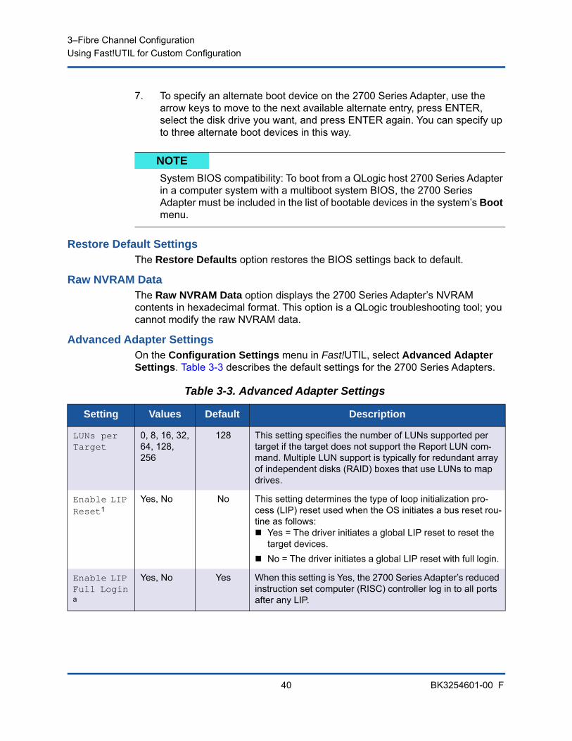
Advanced Adapter SettingsOn the Configuration Settings menu in Fast!UTIL, select Advanced Adapter Settings. Table 3-3 describes the default settings for the 2700 Series Adapters.
NOTE
System BIOS compatibility: To boot from a QLogic host 2700 Series Adapter in a computer system with a multiboot system BIOS, the 2700 Series Adapter must be included in the list of bootable devices in the system’s Boot menu.
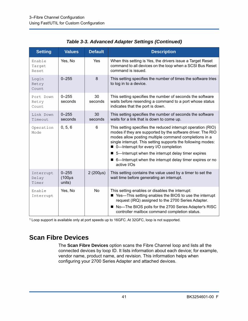
Table 3-3. Advanced Adapter Settings
Setting Values Default Description
LUNs per Target
0, 8, 16, 32, 64, 128, 256
128 This setting specifies the number of LUNs supported per target if the target does not support the Report LUN com-mand. Multiple LUN support is typically for redundant array of independent disks (RAID) boxes that use LUNs to map drives.
Enable LIP Reset1
Yes, No No This setting determines the type of loop initialization pro-cess (LIP) reset used when the OS initiates a bus reset rou-tine as follows: Yes = The driver initiates a global LIP reset to reset the
target devices. No = The driver initiates a global LIP reset with full login.
Enable LIP Full Login
a
Yes, No Yes When this setting is Yes, the 2700 Series Adapter’s reduced instruction set computer (RISC) controller log in to all ports after any LIP.
3–Fibre Channel ConfigurationUsing Fast!UTIL for Custom Configuration
41 BK3254601-00 F
Scan Fibre DevicesThe Scan Fibre Devices option scans the Fibre Channel loop and lists all the connected devices by loop ID. It lists information about each device; for example, vendor name, product name, and revision. This information helps when configuring your 2700 Series Adapter and attached devices.
Enable Target Reset
Yes, No Yes When this setting is Yes, the drivers issue a Target Reset command to all devices on the loop when a SCSI Bus Reset command is issued.
Login Retry Count
0–255 8 This setting specifies the number of times the software tries to log in to a device.
Port Down Retry Count
0–255 seconds
30 seconds
This setting specifies the number of seconds the software waits before resending a command to a port whose status indicates that the port is down.
Link Down Timeout
0–255 seconds
30 seconds
This setting specifies the number of seconds the software waits for a link that is down to come up.
Operation Mode
0, 5, 6 6 This setting specifies the reduced interrupt operation (RIO) modes if they are supported by the software driver. The RIO modes allow posting multiple command completions in a single interrupt. This setting supports the following modes: 0—Interrupt for every I/O completion 5—Interrupt when the interrupt delay timer expires 6—Interrupt when the interrupt delay timer expires or no
active I/Os
Interrupt Delay Timer
0–255 (100μs units)
2 (200μs) This setting contains the value used by a timer to set the wait time before generating an interrupt.
Enable Interrupt
Yes, No No This setting enables or disables the interrupt: Yes—This setting enables the BIOS to use the interrupt
request (IRQ) assigned to the 2700 Series Adapter. No—The BIOS polls for the 2700 Series Adapter's RISC
controller mailbox command completion status.
1 Loop support is available only at port speeds up to 16GFC. At 32GFC, loop is not supported.
Table 3-3. Advanced Adapter Settings (Continued)
Setting Values Default Description
3–Fibre Channel ConfigurationUsing Fast!UTIL for Custom Configuration
42 BK3254601-00 F
Fibre Disk UtilityThe Fibre Disk Utility option scans the Fibre Channel loop and lists all the connected devices by loop ID. You can select a Fibre Channel hard disk and do one of the following tasks:
Perform a low-level format Verify the disk media Verify the disk data (Some targets do not support this feature.) Select a disk device
Loopback Data TestThe Loopback Data Test option allows you to perform the following loopback tests:
External loopback data test Internal loopback data test
Select AdapterIf you have a multiport or multiple 2700 Series Adapters in the system, use the Select Adapter option to select and then configure or view the settings of a specific 2700 Series Adapter or one of its ports.
Exit Fast!UTILThe Exit Fast!UTIL option allows you to exit the utility and reboot the system. After making changes to the 2700 Series Adapter in Fast!UTIL, make sure you save the changes before you reboot the system.
CAUTION
Performing a low-level format destroys all data on the disk.
NOTE
When running an external loopback data test, make sure that the Fibre Channel link is up or a loopback plug is attached to the 2700 Series Adapter before starting the test.
3–Fibre Channel ConfigurationSetting Fibre Channel Adapter Parameters
43 BK3254601-00 F
Setting Fibre Channel Adapter ParametersUse QConvergeConsole to set Fibre Channel adapter parameters:
Setting Fibre Channel Adapter Parameters with QConvergeConsole GUI
Setting Fibre Channel Adapter Parameters with Interactive QConvergeConsole CLI
Setting Fibre Channel Adapter Parameters with Noninteractive QConvergeConsole CLI
Setting Fibre Channel Adapter Parameters with QConvergeConsole GUI
For information about how to set Fibre Channel adapter parameters using QConvergeConsole GUI, refer to the topic about managing Fibre Channel and Fibre Channel over Ethernet (FCoE) adapter ports in the QConvergeConsole Help.
Setting Fibre Channel Adapter Parameters with Interactive QConvergeConsole CLI
To set Fibre Channel adapter parameters with interactive QConvergeConsole CLI:
1. On the Fibre Channel Adapter Configuration menu, select HBA Parameters.
2. On the port menu, select a port to open the HBA Parameters menu.
3. On the HBA Parameters menu, select the Configure HBA Parameters option to open the Configure Parameters menu.
For more information, refer to the section about the Fibre Channel interactive commands in the User’s Guide—QConvergeConsole CLI (part number SN0054667-00).
NOTE
The QLE2742 32Gbps FC HBA does not link up with the Auto setting when it is connected to a Dell EMC S4148U-ON switch.
3–Fibre Channel ConfigurationConfiguring Target Persistent Binding
44 BK3254601-00 F
Setting Fibre Channel Adapter Parameters with Noninteractive QConvergeConsole CLI
For information about how to set Fibre Channel adapter parameters using the noninteractive mode of QConvergeConsole CLI, refer to the section about the Fibre Channel noninteractive commands in the User’s Guide—QConvergeConsole CLI (part number SN0054667-00).
Configuring Target Persistent Binding
Use QConvergeConsole to configure target persistent binding:
Configuring Persistent Binding with QConvergeConsole GUI
Configuring Persistent Binding with Interactive QConvergeConsole CLI
Configuring Persistent Binding with Noninteractive QConvergeConsole CLI
Configuring Persistent Binding with QConvergeConsole GUITo bind target devices attached to an adapter port using QConvergeConsole GUI:
1. In the system tree, expand a Fibre Channel node.
2. In the system tree for a 2700 Series Adapter, select the physical port number.
3. Click the Targets tab, and then click the Target Persistent Binding tab.
4. Choose the binding options:
Select the Bind All check box to bind all the devices listed to adapter ports.
Select the Bind check box if you want to configure a specific port and bind it to the target ID that you have selected from the Target ID list. If you do not want to configure the port, clear the check box. If you clear the check box, the corresponding port is unconfigured.
5. To save the configuration changes, click Save.
6. If the Security Check dialog box appears, type the password in the Enter Password box, and then click OK.
7. The system overwrites any previously saved configuration for the current adapter and displays a message box. Click OK to close the message box.
NOTE
Target persistent binding is supported only on Windows.
3–Fibre Channel ConfigurationConfiguring Target Persistent Binding
45 BK3254601-00 F
For more information, refer to the topic about binding target devices in the QConvergeConsole Help.
Configuring Persistent Binding with Interactive QConvergeConsole CLI
To bind a target using interactive QConvergeConsole CLI:
1. On the Fibre Channel Adapter Configuration menu, select Target Persistent Bindings.
2. On the port menu, select a port and then select Bind Target(s) to bind a target to a port.
3. Select a target and specify a target ID to open the Target Persistent Binding – FC Port Configuration menu with options to select more targets, save changes, or cancel the binding operation.
For more information, refer to the section about Fibre Channel interactive commands in the User’s Guide—QConvergeConsole CLI (part number SN0054667-00).
Configuring Persistent Binding with Noninteractive QConvergeConsole CLI
To bind a selected target to a specific adapter using the noninteractive mode of QConvergeConsole CLI, issue the following command:
# qaucli -pr fc -p (<hba instance> | <hba wwpn>) (<target wwnn> <target wwpn> <target port id> <target id>)
Where:
For more information, refer to the section about Fibre Channel noninteractive commands in the User’s Guide—QConvergeConsole CLI (part number SN0054667-00).
hba instance = Adapter number (use the -g command to find)
hba wwnn = Worldwide node name of the adapter
hba wwpn = Worldwide port name of the adapter
target wwnn = Worldwide node name of the target
target wwpn = Worldwide port name of the target
target port id = Port ID of the target
target id = ID to which the target is bound
3–Fibre Channel ConfigurationConfiguring Boot Devices
46 BK3254601-00 F
Configuring Boot DevicesUse QConvergeConsole or Fast!UTIL to configure boot devices:
Configuring Boot Devices with QConvergeConsole GUI
Configuring Boot Devices with Interactive QConvergeConsole CLI
Configuring Boot Devices with Noninteractive QConvergeConsole CLI
Configuring Boot Devices with the BIOS
Configuring Boot Devices with QConvergeConsole GUIFor information about configuring boot devices with QConvergeConsole GUI, refer to the topics about HBA parameters, viewing or modifying port parameters, and boot device selection in the QConvergeConsole Help.
Configuring Boot Devices with Interactive QConvergeConsole CLI
On the Fibre Channel Adapter Configuration menu, select Boot Devices Configuration to open the Boot Device Settings menu with options to view and configure boot devices.
For information, refer to the section about the Fibre Channel interactive commands in the User’s Guide—QConvergeConsole CLI (part number SN0054667-00).
3–Fibre Channel ConfigurationConfiguring Virtual Ports (NPIV)
47 BK3254601-00 F
Configuring Boot Devices with Noninteractive QConvergeConsole CLI
To set a specific target as the boot device for a specific adapter, issue the following command:
# qaucli -pr fc -e (<hba instance> | <hba wwpn>) <target wwnn> <target wwpn> <target id> <lun id>
Where:
For more information, refer to the “Fibre Channel Noninteractive Commands” section of the User’s Guide—QConvergeConsole CLI (part number SN0054667-00).
Configuring Boot Devices with the BIOSFor information about boot device configuration with the Fast!UTIL BIOS utility, refer to “Using Fast!UTIL for Custom Configuration” on page 37 for information.
Configuring Virtual Ports (NPIV)Use QConvergeConsole to configure virtual ports for N_Port ID virtualization and quality of service:
Configuring NPIV with QConvergeConsole GUI
Configuring NPIV with Interactive QConvergeConsole CLI
Configuring NPIV with Noninteractive QConvergeConsole CLI
Configuring NPIV Quality of Service
Configuring NPIV with QConvergeConsole GUIFor information about using virtualization (NPIV) in QConvergeConsole GUI, refer to in the QConvergeConsole Help.
To access the QConvergeConsole Help system while the GUI utility is running,
point to the gear icon , point to Help, and then click then click Browse Contents. To install QConvergeConsole GUI, see “Installing QConvergeConsole GUI” on page 116.
hba instance = Adapter number (use the -g command to find)
hba wwpn = Worldwide port name of the adapter
target wwnn = Worldwide node name of the target
target wwpn = Worldwide port name of the target
target id = ID to which the target is bound
lun id = ID of the LUN
3–Fibre Channel ConfigurationConfiguring Virtual Ports (NPIV)
48 BK3254601-00 F
Configuring NPIV with Interactive QConvergeConsole CLIFor information about using virtualization (NPIV) in the interactive mode of QConvergeConsole CLI, refer to the User’s Guide—QConvergeConsole CLI (part number SN0054667-00). To download the guide, go to www.cavium.com and click Downloads.
Configuring NPIV with Noninteractive QConvergeConsole CLI To create a virtual port with an automatic WWPN using the noninteractive mode of QConvergeConsole CLI, issue the following command:
# qaucli -pr fc -vp (<hba instance> | <hba wwpn>) create auto
Where:
For more information, refer to the section about Fibre Channel noninteractive commands in the User’s Guide—QConvergeConsole CLI (part number SN0054667-00).
hba instance = Adapter number (use the -g command to find)
hba wwpn = Worldwide port name of the adapter
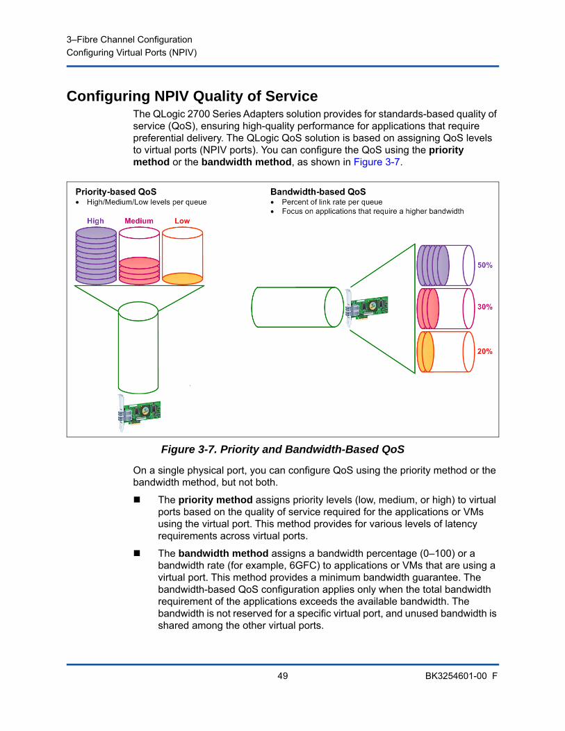
3–Fibre Channel ConfigurationConfiguring Virtual Ports (NPIV)
49 BK3254601-00 F
Configuring NPIV Quality of ServiceThe QLogic 2700 Series Adapters solution provides for standards-based quality of service (QoS), ensuring high-quality performance for applications that require preferential delivery. The QLogic QoS solution is based on assigning QoS levels to virtual ports (NPIV ports). You can configure the QoS using the priority method or the bandwidth method, as shown in Figure 3-7.
Figure 3-7. Priority and Bandwidth-Based QoS
On a single physical port, you can configure QoS using the priority method or the bandwidth method, but not both.
The priority method assigns priority levels (low, medium, or high) to virtual ports based on the quality of service required for the applications or VMs using the virtual port. This method provides for various levels of latency requirements across virtual ports.
The bandwidth method assigns a bandwidth percentage (0–100) or a bandwidth rate (for example, 6GFC) to applications or VMs that are using a virtual port. This method provides a minimum bandwidth guarantee. The bandwidth-based QoS configuration applies only when the total bandwidth requirement of the applications exceeds the available bandwidth. The bandwidth is not reserved for a specific virtual port, and unused bandwidth is shared among the other virtual ports.
3–Fibre Channel ConfigurationConfiguring Virtual Ports (NPIV)
50 BK3254601-00 F
The physical port or WWN always has high priority, independent of the bandwidth or priority scheme chosen for created virtual ports. You need not assign a QoS level to every virtual port that you create. If a QoS level is not assigned to a virtual port, the default is low priority (best effort), independent of the bandwidth or priority scheme. This flexibility allows you to focus on critical applications to ensure that the highest service level is provided. You can modify QoS levels for virtual ports using QConvergeConsole CLI.
To modify QoS levels, the configuration must meet the following hardware and software requirements:
Server operating system: Microsoft® Windows Server 2012 or later
Server support for MSI-X
A QLogic 2700 Series Adapter
Latest version of the QLogic STOR miniport driver, available from Dell:
http://support.dell.com
Fibre Channel switch that supports NPIV
Physical port attached in a point-to-point connection
Setting QoS by BandwidthSetting the QoS by bandwidth allocates up to 80 percent of the physical port’s bandwidth to its virtual ports. The remaining 20 percent is reserved to handle non-QoS applications and virtual ports.
Setting QoS by bandwidth guarantees bandwidth for each virtual port and to the application or virtual machine (VM) associated with that virtual port. The proper QoS setting can prevent bottlenecks that occur when VMs contend for port bandwidth.
Consider how much bandwidth is required to maximize application or VM performance and set the QoS level to 105 percent of that value. For example, if a mission-critical application on a VM requires 1Gb of bandwidth to transmit its data over the fabric, QLogic recommends a 1.05Gb bandwidth for the virtual port.
Alternatively, you can set the virtual port QoS values as a percentage of the total available bandwidth.
NOTE
Setting QoS by bandwidth guarantees a minimum bandwidth to a virtual port, but not a maximum limit. If the application or virtual port requires more bandwidth than the QoS bandwidth value allows and the physical port has available bandwidth, the application receives the additional bandwidth. The port allocates additional bandwidth on demand up to the port capacity or until there is contention for bandwidth among the virtual ports.
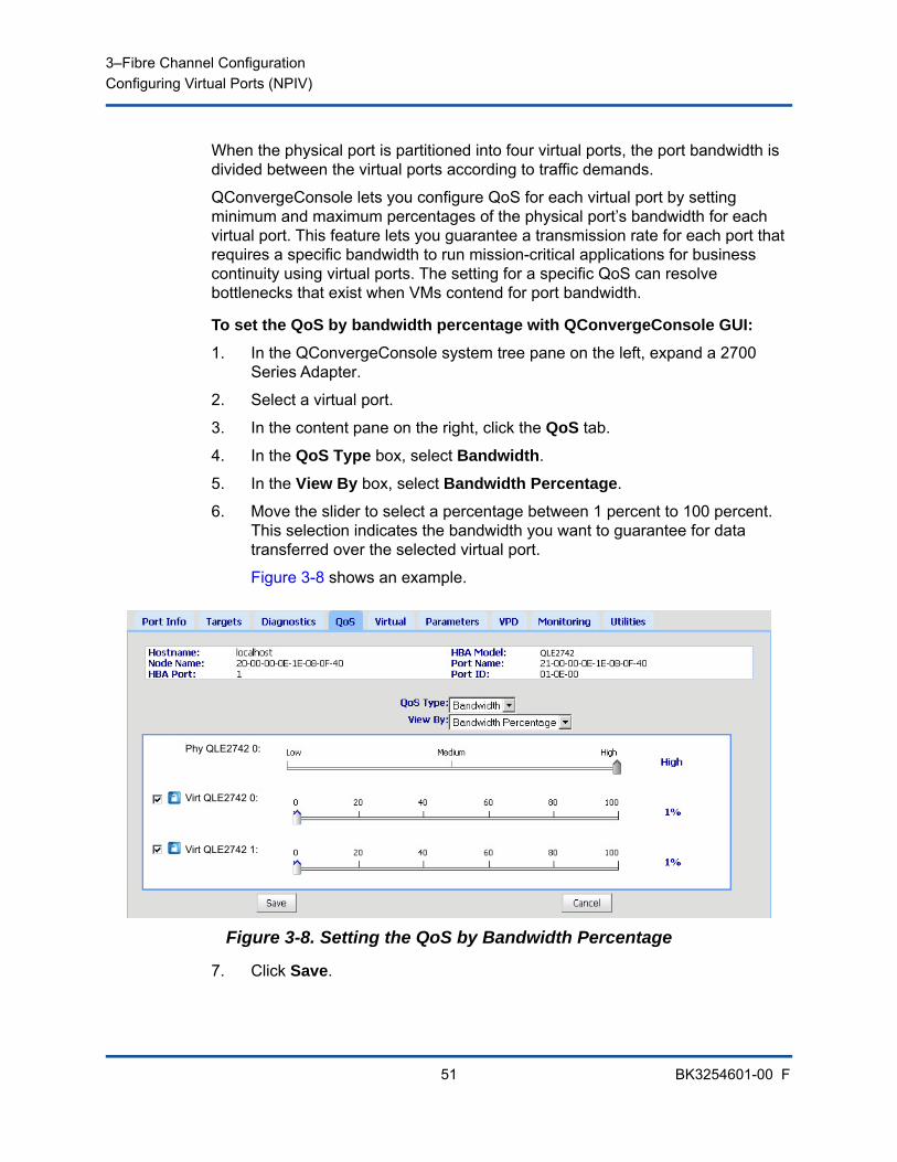
3–Fibre Channel ConfigurationConfiguring Virtual Ports (NPIV)
51 BK3254601-00 F
When the physical port is partitioned into four virtual ports, the port bandwidth is divided between the virtual ports according to traffic demands.
QConvergeConsole lets you configure QoS for each virtual port by setting minimum and maximum percentages of the physical port’s bandwidth for each virtual port. This feature lets you guarantee a transmission rate for each port that requires a specific bandwidth to run mission-critical applications for business continuity using virtual ports. The setting for a specific QoS can resolve bottlenecks that exist when VMs contend for port bandwidth.
To set the QoS by bandwidth percentage with QConvergeConsole GUI:
1. In the QConvergeConsole system tree pane on the left, expand a 2700 Series Adapter.
2. Select a virtual port.
3. In the content pane on the right, click the QoS tab.
4. In the QoS Type box, select Bandwidth.
5. In the View By box, select Bandwidth Percentage.
6. Move the slider to select a percentage between 1 percent to 100 percent. This selection indicates the bandwidth you want to guarantee for data transferred over the selected virtual port.
Figure 3-8 shows an example.
Figure 3-8. Setting the QoS by Bandwidth Percentage
7. Click Save.
Phy QLE2742 0:
Virt QLE2742 0:
Virt QLE2742 1:
QLE2742
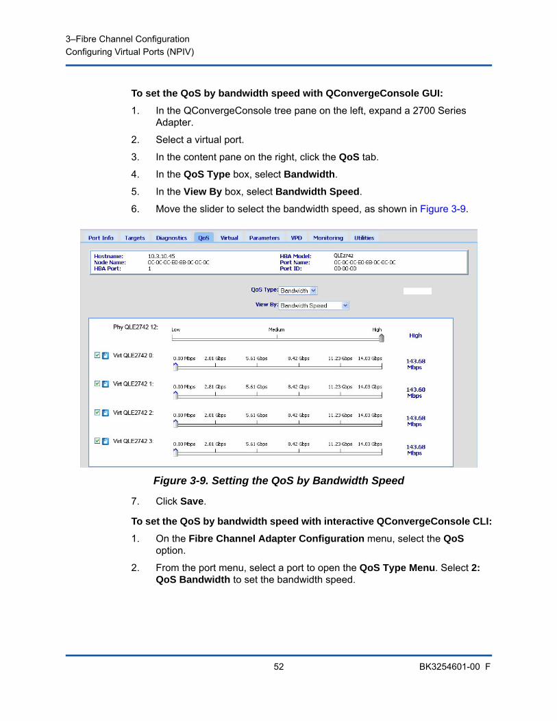
3–Fibre Channel ConfigurationConfiguring Virtual Ports (NPIV)
52 BK3254601-00 F
To set the QoS by bandwidth speed with QConvergeConsole GUI:
1. In the QConvergeConsole tree pane on the left, expand a 2700 Series Adapter.
2. Select a virtual port.
3. In the content pane on the right, click the QoS tab.
4. In the QoS Type box, select Bandwidth.
5. In the View By box, select Bandwidth Speed.
6. Move the slider to select the bandwidth speed, as shown in Figure 3-9.
Figure 3-9. Setting the QoS by Bandwidth Speed
7. Click Save.
To set the QoS by bandwidth speed with interactive QConvergeConsole CLI:
1. On the Fibre Channel Adapter Configuration menu, select the QoS option.
2. From the port menu, select a port to open the QoS Type Menu. Select 2: QoS Bandwidth to set the bandwidth speed.
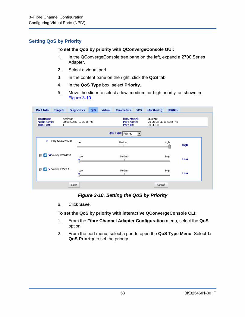
3–Fibre Channel ConfigurationConfiguring Virtual Ports (NPIV)
53 BK3254601-00 F
Setting QoS by Priority
To set the QoS by priority with QConvergeConsole GUI:
1. In the QConvergeConsole tree pane on the left, expand a 2700 Series Adapter.
2. Select a virtual port.
3. In the content pane on the right, click the QoS tab.
4. In the QoS Type box, select Priority.
5. Move the slider to select a low, medium, or high priority, as shown in Figure 3-10.
Figure 3-10. Setting the QoS by Priority
6. Click Save.
To set the QoS by priority with interactive QConvergeConsole CLI:
1. From the Fibre Channel Adapter Configuration menu, select the QoS option.
2. From the port menu, select a port to open the QoS Type Menu. Select 1: QoS Priority to set the priority.
3–Fibre Channel ConfigurationConfiguring Fibre Channel Driver Parameters
54 BK3254601-00 F
Configuring Fibre Channel Driver ParametersUse QConvergeConsole GUI, CLI, or VMware plug-in to configure Fibre Channel driver parameters:
Configuring Fibre Channel Driver Parameters with QConvergeConsole GUI
Configuring Fibre Channel Driver Parameters with Interactive QConvergeConsole CLI
Configuring Fibre Channel Driver Parameters with Noninteractive QConvergeConsole CLI
Configuring Fibre Channel Driver Parameters with QConvergeConsole VMware vCenter Server Plug-in
Configuring Fibre Channel Driver Parameters with QConvergeConsole GUI
Refer to the topics about HBA parameters and viewing or modifying port parameters in the QConvergeConsole Help for information.
Configuring Fibre Channel Driver Parameters with Interactive QConvergeConsole CLI
To configure Fibre Channel driver parameters using interactive QConvergeConsole CLI:
1. On the Fibre Channel Adapter Configuration menu, select HBA Parameters.
2. On the port menu, select a port to open the HBA Parameters menu.
3. On the HBA Parameters menu, select Configure HBA Parameters to open the Configure Parameters menu with options to configure connection options, data rate, frame size, hard loop ID, loop reset delay, BIOS, Fibre Channel tape support, operation mode, interrupt delay timer, login retry count, port down retry count, LIP full login, link down time-out, target reset, LUNS per target, and receive out-of-order frames.
For more information, refer to the section about the Fibre Channel interactive commands in the User’s Guide—QConvergeConsole CLI (part number SN0054667-00).
3–Fibre Channel ConfigurationConfiguring Selective LUNs
55 BK3254601-00 F
Configuring Fibre Channel Driver Parameters with Noninteractive QConvergeConsole CLI
To configure driver settings, issue the following command:
# qaucli -pr fc -fs (<hba instance> | <hba wwpn>) {(<param name> | <param alias>) <param value>}
Where:
For more information, refer to the section about the Fibre Channel noninteractive commands in the User’s Guide—QConvergeConsole CLI (part number SN0054667-00).
Configuring Fibre Channel Driver Parameters with QConvergeConsole VMware vCenter Server Plug-in
For details on how to configure the Fibre Channel driver parameters using the QConvergeConsole plug-in, see the User’s Guide—QConvergeConsole Plug-ins for VMware vSphere (part number SN0054677-00).
Configuring Selective LUNsThe QConvergeConsole GUI cannot be used for configuring selective LUNs.
To configure selective LUNs with the interactive QConvergeConsole CLI, refer to the section about the Fibre Channel interactive commands in the User’s Guide—QConvergeConsole CLI (part number SN0054667-00).
To configure selective LUNs with the noninteractive QConvergeConsole CLI, refer to the section about the Fibre Channel noninteractive commands in the User’s Guide—QConvergeConsole CLI (part number SN0054667-00).
hba instance = Adapter number (use the -g command to find)
hba wwpn = Worldwide port name of the adapter
param name = Name of the parameter
param alias = Alias of the parameter
param value = New value of the parameter
3–Fibre Channel ConfigurationConfiguring OoOFR
56 BK3254601-00 F
Configuring OoOFROut-of-order frame reassembly (OoOFR) reassembles out-of-order frames as they are received, minimizing network congestion by eliminating the retransmission of frames and exchanges. To configure OoOFR, use either QConvergeConsole GUI or CLI.
Configuring OoOFR with QCC GUITo enable OoOFR with QConvergeConsole GUI:
1. In the QConvergeConsole system tree pane on the left, select a Fibre Channel port.
2. In the content pane on the right, click Parameters.
3. Click the Advanced HBA Parameters tab.
4. Select the Enable Receive Out of Order Frame check box.
Configuring OoOFR with Interactive QCC CLITo enable OoOFR with the interactive QConvergeConsole CLI:
1. On the Fibre Channel Adapter Configuration menu, select HBA Parameters.
2. On the port menu, select a port to open the HBA Parameters menu.
3. On the HBA Parameters menu, select Configure HBA Parameters to open the Configure Parameters menu.
4. Select 13: Enable Receive Out Of Order Frame.
Configuring OoOFR with Noninteractive QCC CLITo enable OoOFR in the noninteractive mode of QConvergeConsole CLI, issue one of the following commands:
# qaucli -n <hba instance>|<hba wwpn> EnableReceiveOutOfOrderFrame 1
# qaucli -n <hba instance>|<hba wwpn> EO 1
Where:
To disable OoOFR in the noninteractive mode of QConvergeConsole CLI, issue one of the following commands:
# qaucli -n <hba instance>|<hba wwpn> EnableReceiveOutOfOrderFrame 0
# qaucli -n <hba instance>|<hba wwpn> EO 0
hba instance = Adapter number (use the -g command to find)
hba wwpn = Worldwide port name of the adapter
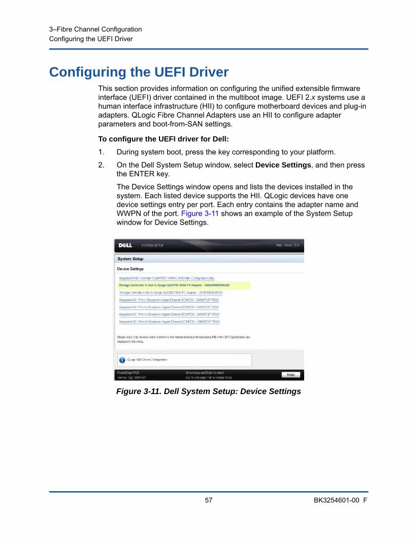
3–Fibre Channel ConfigurationConfiguring the UEFI Driver
57 BK3254601-00 F
Configuring the UEFI DriverThis section provides information on configuring the unified extensible firmware interface (UEFI) driver contained in the multiboot image. UEFI 2.x systems use a human interface infrastructure (HII) to configure motherboard devices and plug-in adapters. QLogic Fibre Channel Adapters use an HII to configure adapter parameters and boot-from-SAN settings.
To configure the UEFI driver for Dell:
1. During system boot, press the key corresponding to your platform.
2. On the Dell System Setup window, select Device Settings, and then press the ENTER key.
The Device Settings window opens and lists the devices installed in the system. Each listed device supports the HII. QLogic devices have one device settings entry per port. Each entry contains the adapter name and WWPN of the port. Figure 3-11 shows an example of the System Setup window for Device Settings.
Figure 3-11. Dell System Setup: Device Settings
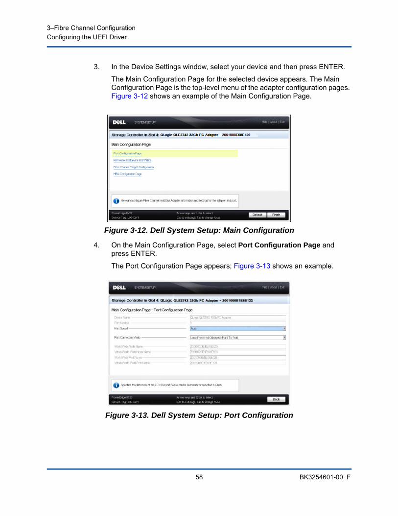
3–Fibre Channel ConfigurationConfiguring the UEFI Driver
58 BK3254601-00 F
3. In the Device Settings window, select your device and then press ENTER.
The Main Configuration Page for the selected device appears. The Main Configuration Page is the top-level menu of the adapter configuration pages. Figure 3-12 shows an example of the Main Configuration Page.
Figure 3-12. Dell System Setup: Main Configuration
4. On the Main Configuration Page, select Port Configuration Page and press ENTER.
The Port Configuration Page appears; Figure 3-13 shows an example.
Figure 3-13. Dell System Setup: Port Configuration
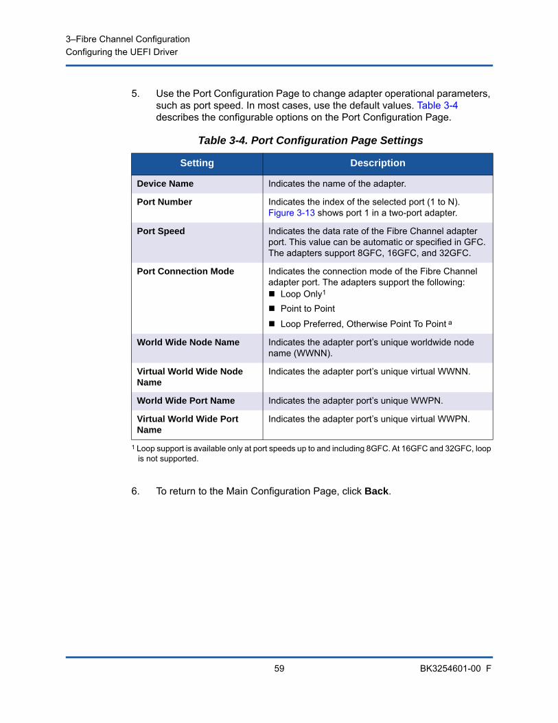
3–Fibre Channel ConfigurationConfiguring the UEFI Driver
59 BK3254601-00 F
5. Use the Port Configuration Page to change adapter operational parameters, such as port speed. In most cases, use the default values. Table 3-4 describes the configurable options on the Port Configuration Page.
6. To return to the Main Configuration Page, click Back.
Table 3-4. Port Configuration Page Settings
Setting Description
Device Name Indicates the name of the adapter.
Port Number Indicates the index of the selected port (1 to N). Figure 3-13 shows port 1 in a two-port adapter.
Port Speed Indicates the data rate of the Fibre Channel adapter port. This value can be automatic or specified in GFC. The adapters support 8GFC, 16GFC, and 32GFC.
Port Connection Mode Indicates the connection mode of the Fibre Channel adapter port. The adapters support the following: Loop Only1 Point to Point
Loop Preferred, Otherwise Point To Point a
1 Loop support is available only at port speeds up to and including 8GFC. At 16GFC and 32GFC, loop is not supported.
World Wide Node Name Indicates the adapter port’s unique worldwide node name (WWNN).
Virtual World Wide Node Name
Indicates the adapter port’s unique virtual WWNN.
World Wide Port Name Indicates the adapter port’s unique WWPN.
Virtual World Wide Port Name
Indicates the adapter port’s unique virtual WWPN.
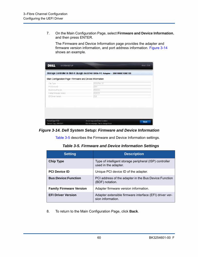
3–Fibre Channel ConfigurationConfiguring the UEFI Driver
60 BK3254601-00 F
7. On the Main Configuration Page, select Firmware and Device Information, and then press ENTER.
The Firmware and Device Information page provides the adapter and firmware version information, and port address information. Figure 3-14 shows an example.
Figure 3-14. Dell System Setup: Firmware and Device Information
Table 3-5 describes the Firmware and Device Information settings.
8. To return to the Main Configuration Page, click Back.
Table 3-5. Firmware and Device Information Settings
Setting Description
Chip Type Type of intelligent storage peripheral (ISP) controller used in the adapter.
PCI Device ID Unique PCI device ID of the adapter.
Bus:Device:Function PCI address of the adapter in the Bus:Device:Function (BDF) notation.
Family Firmware Version Adapter firmware version information.
EFI Driver Version Adapter extensible firmware interface (EFI) driver ver-sion information.

3–Fibre Channel ConfigurationConfiguring the UEFI Driver
61 BK3254601-00 F
9. On the Main Configuration Page, select Fibre Channel Target Configuration, and then press ENTER.
The Fibre Channel Target Configuration page appears. Figure 3-15 shows an example.
Figure 3-15. Fibre Channel Target Configuration
3–Fibre Channel ConfigurationConfiguring the UEFI Driver
62 BK3254601-00 F
10. On the Fibre Channel Target Configuration page, select SAN storage devices for boot from SAN. With selective boot scan enabled, the target configuration determines which target LUNs to map. All other devices are ignored. Table 3-6 describes the Fibre Channel Target Configuration settings.
11. To return to the Main Configuration Page, click Back.
Table 3-6. Fibre Channel Target Configuration Settings
Setting Description
Boot Scan Selection Specifies the adapter initiator behavior for booting the system from the specified Fibre Channel storage target(s) or fabric discovered target(s).
First FC Target World Wide Port Name
Specifies the WWPN of the first Fibre Channel stor-age target.
First FC Target LUN Specifies the LUN of the first Fibre Channel storage target.
Second FC Target World Wide Port Name
Specifies the WWPN of the second Fibre Channel storage target.
Second FC Target LUN Specifies the LUN of the second Fibre Channel stor-age target.
NOTE
System UEFI compatibility: To boot from a QLogic host 2700 Series Adapter in a computer system with a multiboot system UEFI, the 2700 Series Adapter must be included as the first device in the list of bootable devices in the system’s Boot menu.
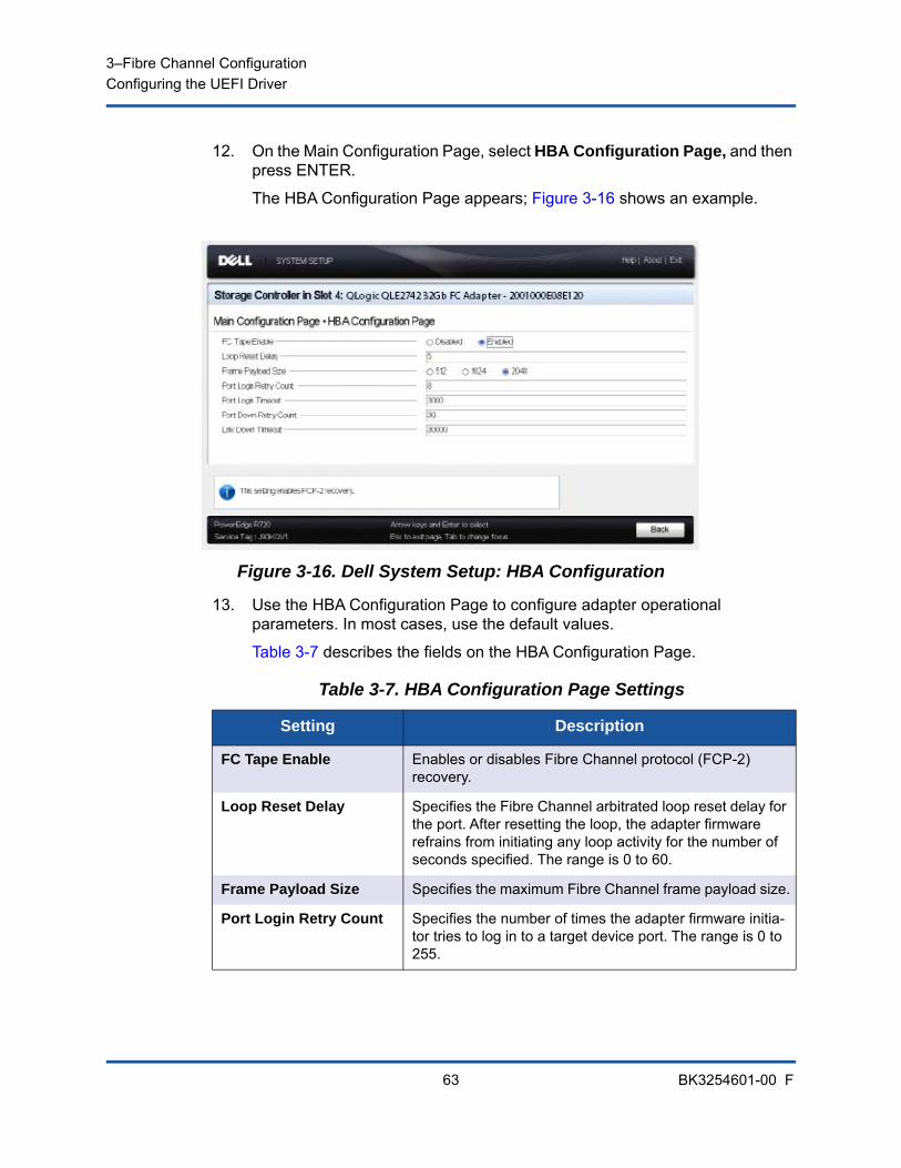
3–Fibre Channel ConfigurationConfiguring the UEFI Driver
63 BK3254601-00 F
12. On the Main Configuration Page, select HBA Configuration Page, and then press ENTER.
The HBA Configuration Page appears; Figure 3-16 shows an example.
Figure 3-16. Dell System Setup: HBA Configuration
13. Use the HBA Configuration Page to configure adapter operational parameters. In most cases, use the default values.
Table 3-7 describes the fields on the HBA Configuration Page.
Table 3-7. HBA Configuration Page Settings
Setting Description
FC Tape Enable Enables or disables Fibre Channel protocol (FCP-2) recovery.
Loop Reset Delay Specifies the Fibre Channel arbitrated loop reset delay for the port. After resetting the loop, the adapter firmware refrains from initiating any loop activity for the number of seconds specified. The range is 0 to 60.
Frame Payload Size Specifies the maximum Fibre Channel frame payload size.
Port Login Retry Count Specifies the number of times the adapter firmware initia-tor tries to log in to a target device port. The range is 0 to 255.
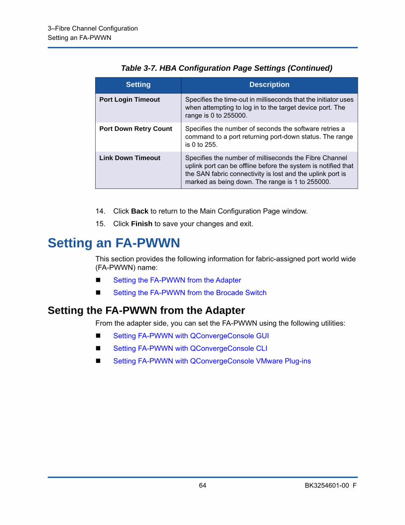
3–Fibre Channel ConfigurationSetting an FA-PWWN
64 BK3254601-00 F
14. Click Back to return to the Main Configuration Page window.
15. Click Finish to save your changes and exit.
Setting an FA-PWWNThis section provides the following information for fabric-assigned port world wide (FA-PWWN) name:
Setting the FA-PWWN from the Adapter
Setting the FA-PWWN from the Brocade Switch
Setting the FA-PWWN from the AdapterFrom the adapter side, you can set the FA-PWWN using the following utilities:
Setting FA-PWWN with QConvergeConsole GUI
Setting FA-PWWN with QConvergeConsole CLI
Setting FA-PWWN with QConvergeConsole VMware Plug-ins
Port Login Timeout Specifies the time-out in milliseconds that the initiator uses when attempting to log in to the target device port. The range is 0 to 255000.
Port Down Retry Count Specifies the number of seconds the software retries a command to a port returning port-down status. The range is 0 to 255.
Link Down Timeout Specifies the number of milliseconds the Fibre Channel uplink port can be offline before the system is notified that the SAN fabric connectivity is lost and the uplink port is marked as being down. The range is 1 to 255000.
Table 3-7. HBA Configuration Page Settings (Continued)
Setting Description
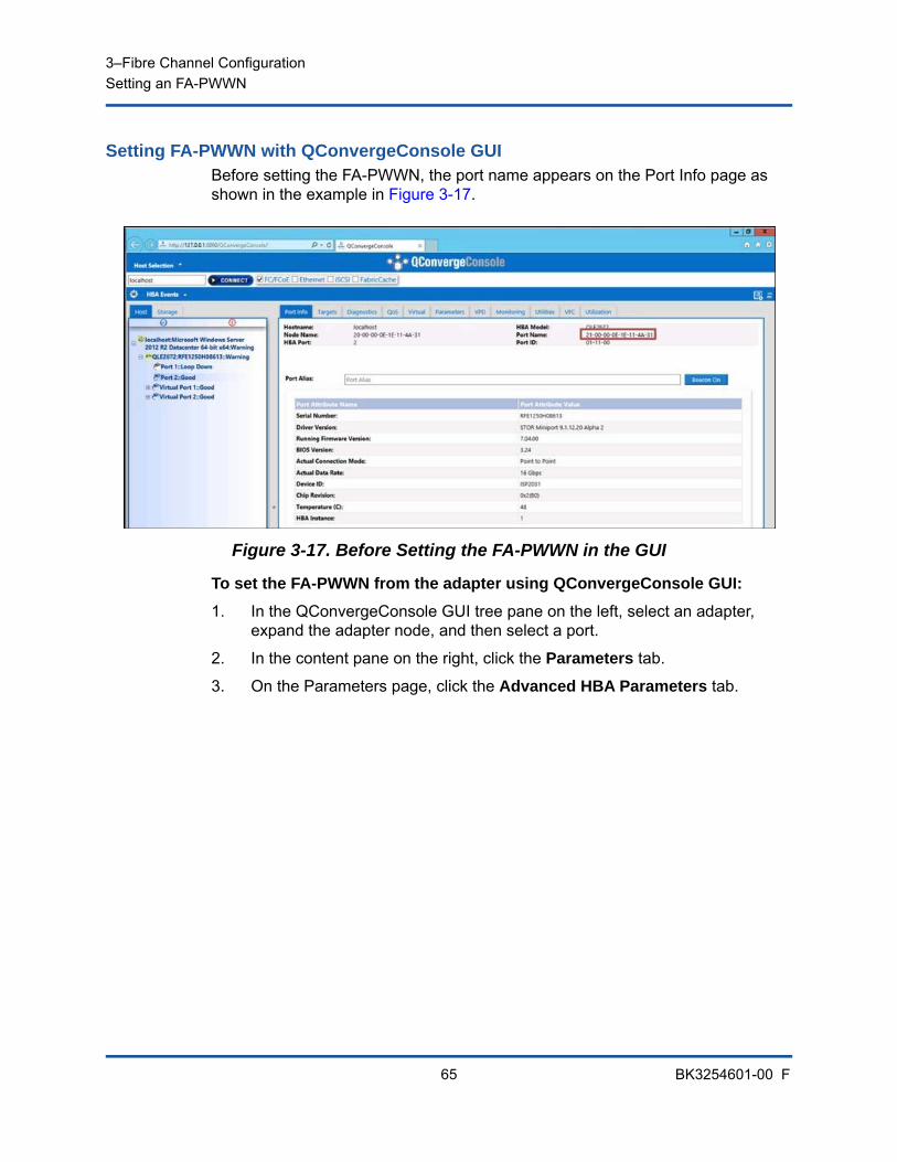
3–Fibre Channel ConfigurationSetting an FA-PWWN
65 BK3254601-00 F
Setting FA-PWWN with QConvergeConsole GUIBefore setting the FA-PWWN, the port name appears on the Port Info page as shown in the example in Figure 3-17.
Figure 3-17. Before Setting the FA-PWWN in the GUI
To set the FA-PWWN from the adapter using QConvergeConsole GUI:
1. In the QConvergeConsole GUI tree pane on the left, select an adapter, expand the adapter node, and then select a port.
2. In the content pane on the right, click the Parameters tab.
3. On the Parameters page, click the Advanced HBA Parameters tab.
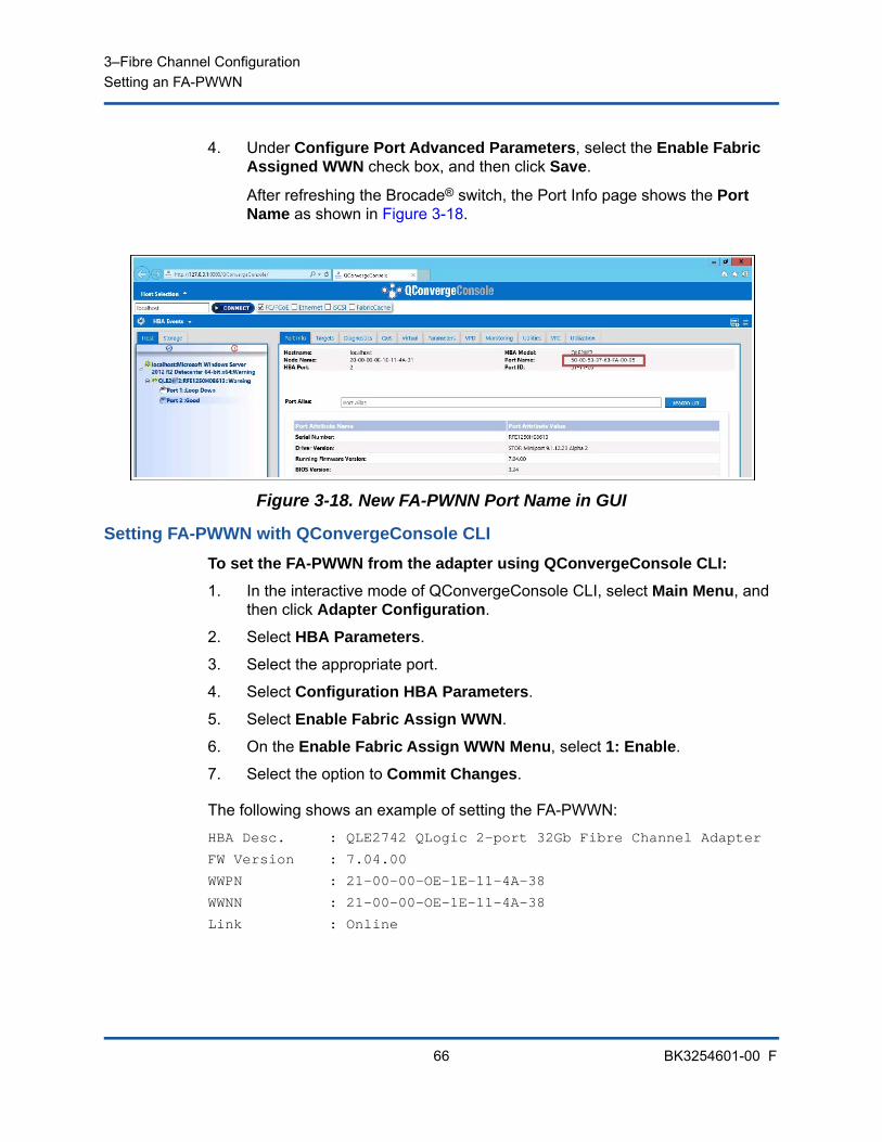
3–Fibre Channel ConfigurationSetting an FA-PWWN
66 BK3254601-00 F
4. Under Configure Port Advanced Parameters, select the Enable Fabric Assigned WWN check box, and then click Save.
After refreshing the Brocade® switch, the Port Info page shows the Port Name as shown in Figure 3-18.
Figure 3-18. New FA-PWNN Port Name in GUI
Setting FA-PWWN with QConvergeConsole CLI
To set the FA-PWWN from the adapter using QConvergeConsole CLI:
1. In the interactive mode of QConvergeConsole CLI, select Main Menu, and then click Adapter Configuration.
2. Select HBA Parameters.
3. Select the appropriate port.
4. Select Configuration HBA Parameters.
5. Select Enable Fabric Assign WWN.
6. On the Enable Fabric Assign WWN Menu, select 1: Enable.
7. Select the option to Commit Changes.
The following shows an example of setting the FA-PWWN:
HBA Desc. : QLE2742 QLogic 2-port 32Gb Fibre Channel Adapter
FW Version : 7.04.00
WWPN : 21-00-00-OE-1E-11-4A-38
WWNN : 21-00-00-OE-1E-11-4A-38
Link : Online
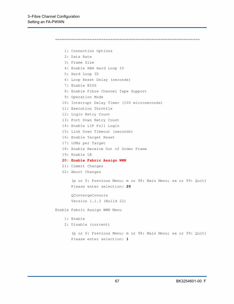
3–Fibre Channel ConfigurationSetting an FA-PWWN
67 BK3254601-00 F
===============================================================
1: Connection Options
2: Data Rate
3: Frame Size
4: Enable HBA Hard Loop ID
5: Hard Loop ID
6: Loop Reset Delay (seconds)
7: Enable BIOS
8: Enable Fibre Channel Tape Support
9: Operation Mode
10: Interrupt Delay Timer (100 microseconds)
11: Execution Throttle
12: Login Retry Count
13: Port Down Retry Count
14: Enable LIP Full Login
15: Link Down Timeout (seconds)
16: Enable Target Reset
17: LUNs per Target
18: Enable Receive Out of Order Frame
19: Enable LR
20: Enable Fabric Assign WWN
21: Commit Changes
22: Abort Changes
(p or 0: Previous Menu; m or 98: Main Menu; ex or 99: Quit)
Please enter selection: 20
QConvergeConsole
Version 1.1.3 (Build 22)
Enable Fabric Assign WWN Menu
1: Enable
2: Disable (current)
(p or 0: Previous Menu; m or 98: Main Menu; ex or 99: Quit)
Please enter selection: 1
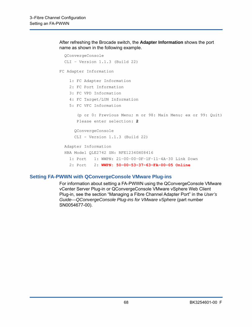
3–Fibre Channel ConfigurationSetting an FA-PWWN
68 BK3254601-00 F
After refreshing the Brocade switch, the Adapter Information shows the port name as shown in the following example.
QConvergeConsole
CLI - Version 1.1.3 (Build 22)
FC Adapter Information
1: FC Adapter Information
2: FC Port Information
3: FC VPD Information
4: FC Target/LUN Information
5: FC VFC Information
(p or 0: Previous Menu; m or 98: Main Menu; ex or 99: Quit)
Please enter selection: 2
QConvergeConsole
CLI - Version 1.1.3 (Build 22)
Adapter Information
HBA Model QLE2742 SN: RFE12340H08416
1: Port 1: WWPN: 21-00-00-0F-1F-11-4A-30 Link Down
2: Port 2: WWPN: 50-00-53-37-63-FA-00-05 Online
Setting FA-PWWN with QConvergeConsole VMware Plug-insFor information about setting a FA-PWWN using the QConvergeConsole VMware vCenter Server Plug-in or QConvergeConsole VMware vSphere Web Client Plug-in, see the section “Managing a Fibre Channel Adapter Port” in the User’s Guide—QConvergeConsole Plug-ins for VMware vSphere (part number SN0054677-00).
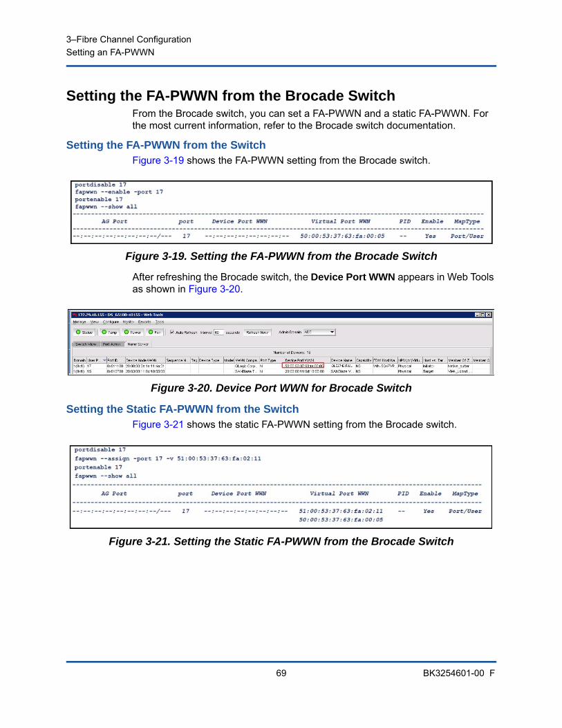
3–Fibre Channel ConfigurationSetting an FA-PWWN
69 BK3254601-00 F
Setting the FA-PWWN from the Brocade SwitchFrom the Brocade switch, you can set a FA-PWWN and a static FA-PWWN. For the most current information, refer to the Brocade switch documentation.
Setting the FA-PWWN from the SwitchFigure 3-19 shows the FA-PWWN setting from the Brocade switch.
Figure 3-19. Setting the FA-PWWN from the Brocade Switch
After refreshing the Brocade switch, the Device Port WWN appears in Web Tools as shown in Figure 3-20.
Figure 3-20. Device Port WWN for Brocade Switch
Setting the Static FA-PWWN from the SwitchFigure 3-21 shows the static FA-PWWN setting from the Brocade switch.
Figure 3-21. Setting the Static FA-PWWN from the Brocade Switch
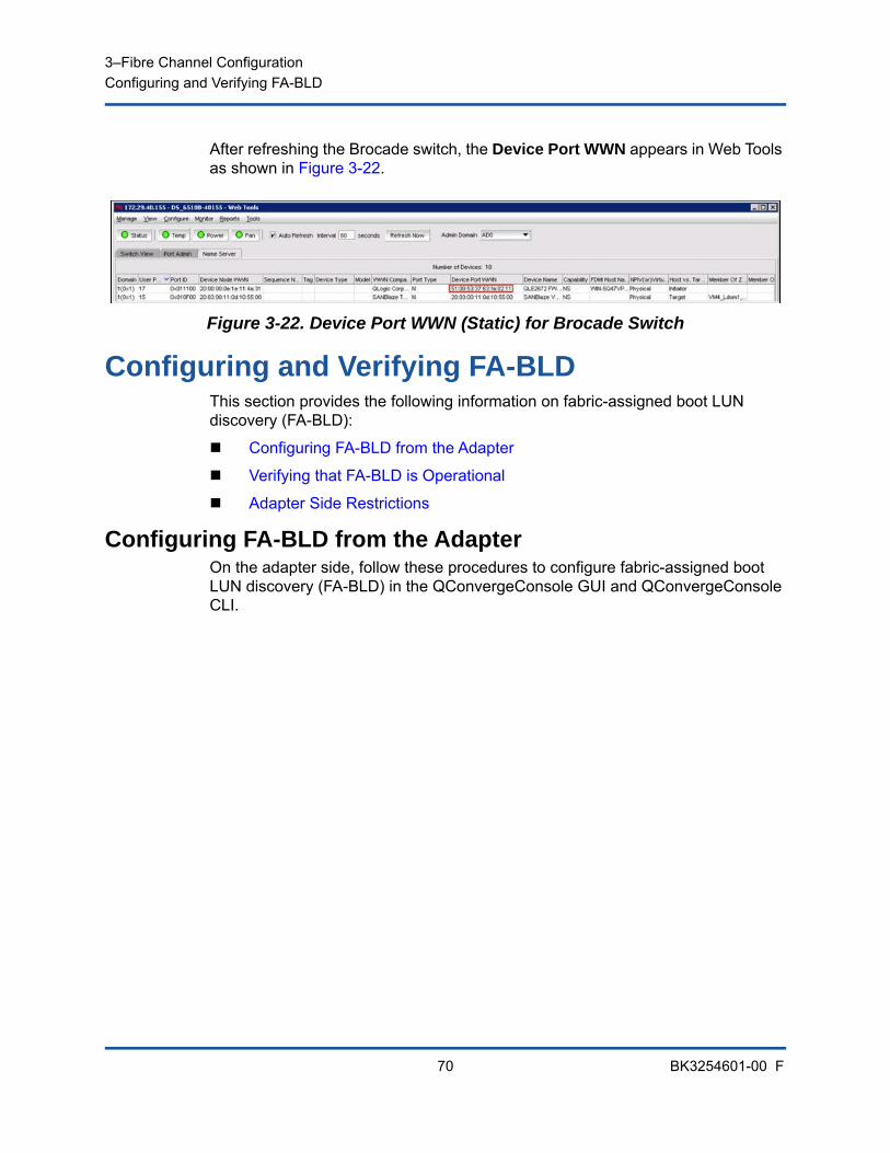
3–Fibre Channel ConfigurationConfiguring and Verifying FA-BLD
70 BK3254601-00 F
After refreshing the Brocade switch, the Device Port WWN appears in Web Tools as shown in Figure 3-22.
Figure 3-22. Device Port WWN (Static) for Brocade Switch
Configuring and Verifying FA-BLDThis section provides the following information on fabric-assigned boot LUN discovery (FA-BLD):
Configuring FA-BLD from the Adapter
Verifying that FA-BLD is Operational
Adapter Side Restrictions
Configuring FA-BLD from the AdapterOn the adapter side, follow these procedures to configure fabric-assigned boot LUN discovery (FA-BLD) in the QConvergeConsole GUI and QConvergeConsole CLI.
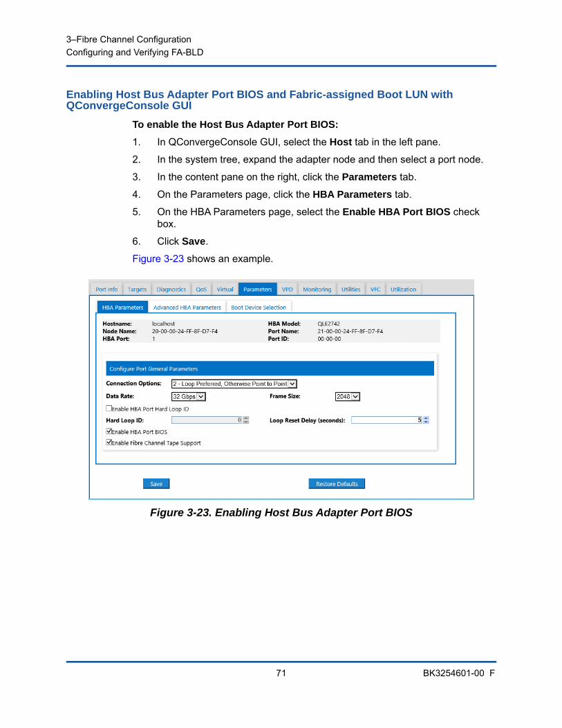
3–Fibre Channel ConfigurationConfiguring and Verifying FA-BLD
71 BK3254601-00 F
Enabling Host Bus Adapter Port BIOS and Fabric-assigned Boot LUN with QConvergeConsole GUI
To enable the Host Bus Adapter Port BIOS:
1. In QConvergeConsole GUI, select the Host tab in the left pane.
2. In the system tree, expand the adapter node and then select a port node.
3. In the content pane on the right, click the Parameters tab.
4. On the Parameters page, click the HBA Parameters tab.
5. On the HBA Parameters page, select the Enable HBA Port BIOS check box.
6. Click Save.
Figure 3-23 shows an example.
Figure 3-23. Enabling Host Bus Adapter Port BIOS
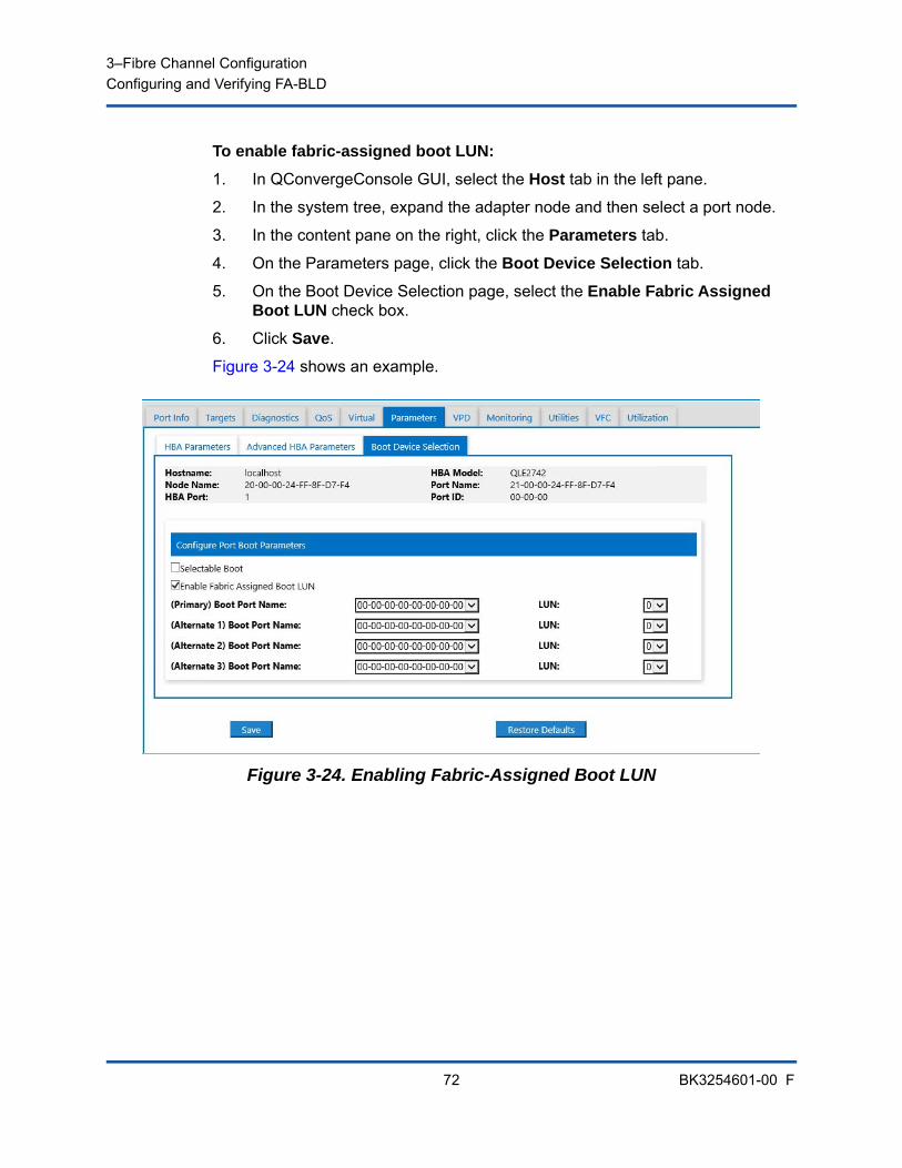
3–Fibre Channel ConfigurationConfiguring and Verifying FA-BLD
72 BK3254601-00 F
To enable fabric-assigned boot LUN:
1. In QConvergeConsole GUI, select the Host tab in the left pane.
2. In the system tree, expand the adapter node and then select a port node.
3. In the content pane on the right, click the Parameters tab.
4. On the Parameters page, click the Boot Device Selection tab.
5. On the Boot Device Selection page, select the Enable Fabric Assigned Boot LUN check box.
6. Click Save.
Figure 3-24 shows an example.
Figure 3-24. Enabling Fabric-Assigned Boot LUN
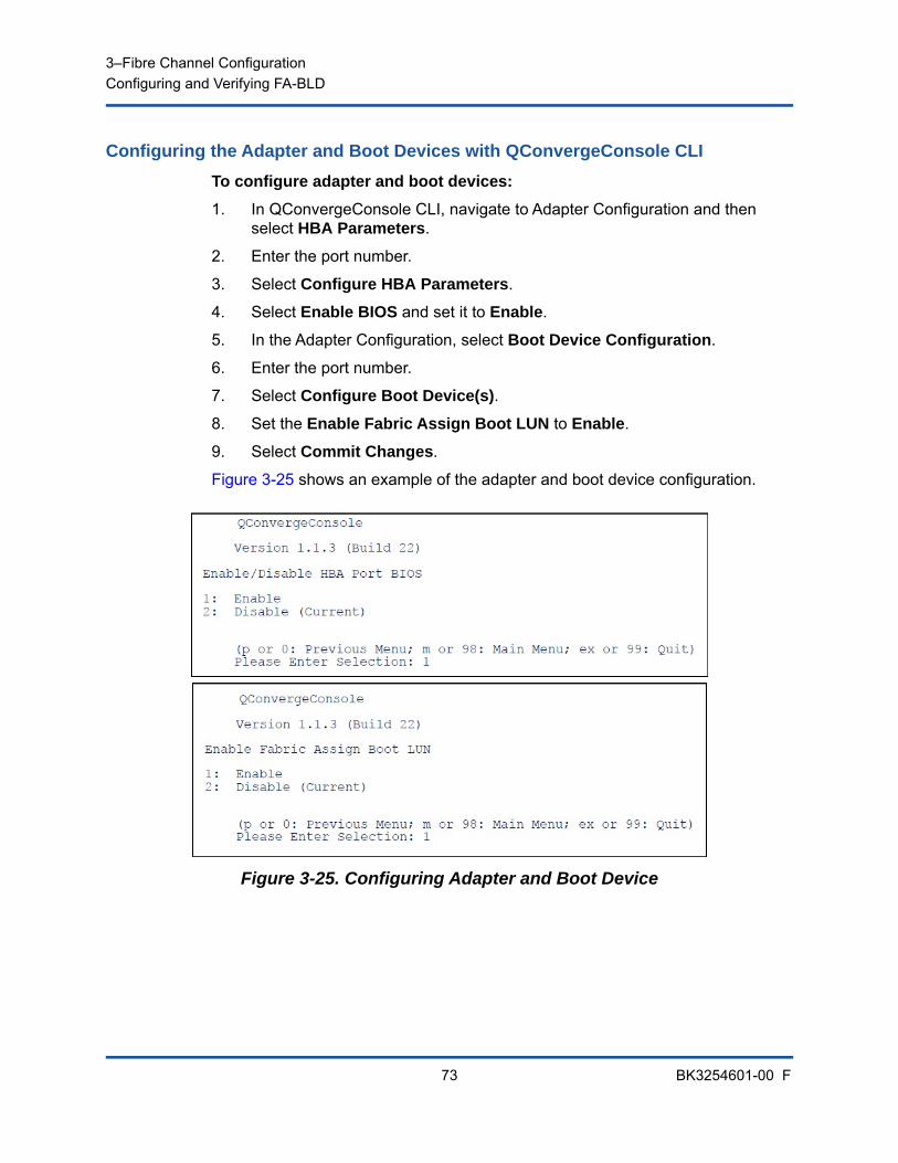
3–Fibre Channel ConfigurationConfiguring and Verifying FA-BLD
73 BK3254601-00 F
Configuring the Adapter and Boot Devices with QConvergeConsole CLI
To configure adapter and boot devices:
1. In QConvergeConsole CLI, navigate to Adapter Configuration and then select HBA Parameters.
2. Enter the port number.
3. Select Configure HBA Parameters.
4. Select Enable BIOS and set it to Enable.
5. In the Adapter Configuration, select Boot Device Configuration.
6. Enter the port number.
7. Select Configure Boot Device(s).
8. Set the Enable Fabric Assign Boot LUN to Enable.
9. Select Commit Changes.
Figure 3-25 shows an example of the adapter and boot device configuration.
Figure 3-25. Configuring Adapter and Boot Device
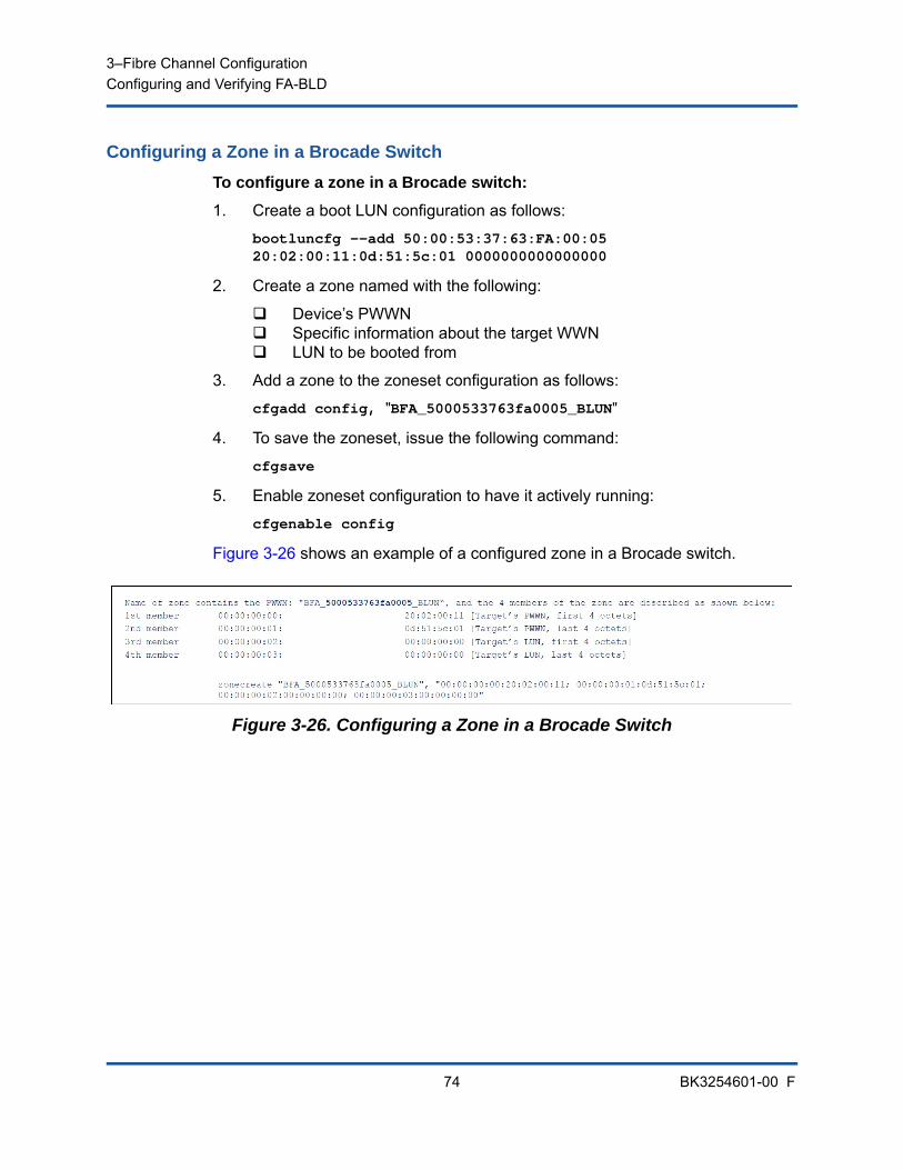
3–Fibre Channel ConfigurationConfiguring and Verifying FA-BLD
74 BK3254601-00 F
Configuring a Zone in a Brocade Switch
To configure a zone in a Brocade switch:
1. Create a boot LUN configuration as follows:
bootluncfg --add 50:00:53:37:63:FA:00:05 20:02:00:11:0d:51:5c:01 0000000000000000
2. Create a zone named with the following:
Device’s PWWN Specific information about the target WWN LUN to be booted from
3. Add a zone to the zoneset configuration as follows:
cfgadd config, "BFA_5000533763fa0005_BLUN"
4. To save the zoneset, issue the following command:
cfgsave
5. Enable zoneset configuration to have it actively running:
cfgenable config
Figure 3-26 shows an example of a configured zone in a Brocade switch.
Figure 3-26. Configuring a Zone in a Brocade Switch
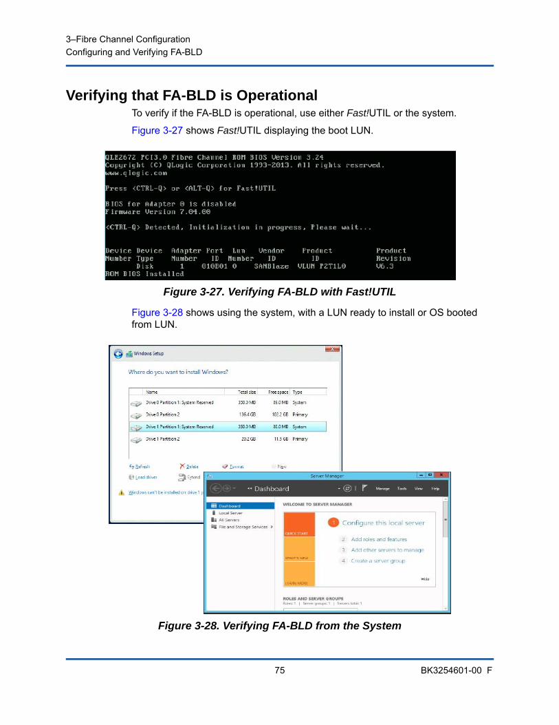
3–Fibre Channel ConfigurationConfiguring and Verifying FA-BLD
75 BK3254601-00 F
Verifying that FA-BLD is OperationalTo verify if the FA-BLD is operational, use either Fast!UTIL or the system.
Figure 3-27 shows Fast!UTIL displaying the boot LUN.
Figure 3-27. Verifying FA-BLD with Fast!UTIL
Figure 3-28 shows using the system, with a LUN ready to install or OS booted from LUN.
Figure 3-28. Verifying FA-BLD from the System
3–Fibre Channel ConfigurationUsing a Fabric-Assigned Boot LUN
76 BK3254601-00 F
Adapter Side RestrictionsThe known fabric-assigned port world wide name (FA-PWNN) and FA-BLD restrictions include the following:
Cannot be fully enabled from Fast!UTIL
Do not use Restore Defaults from Fast!UTIL, QConvergeConsole GUI, or QConvergeConsole CLI. Doing so causes these capabilities to become disabled.
Using a Fabric-Assigned Boot LUNThis section describes how to use a fabric-assigned boot LUN in the following utilities:
Using a Fabric-Assigned Boot LUN in QConvergeConsole GUI
Using a Fabric-Assigned Boot LUN in Interactive QConvergeConsole CLI
Using a Fabric-Assigned Boot LUN with Noninteractive QConvergeConsole CLI
Using a Fabric-Assigned Boot LUN with QConvergeConsole Plug-ins
Using a Fabric-Assigned Boot LUN in QConvergeConsole GUIFor details about how to use a fabric-assigned LUN in QConvergeConsole GUI, refer to the “Fabric-Assigned Boot LUN” topic in the QConvergeConsole Help.
Using a Fabric-Assigned Boot LUN in Interactive QConvergeConsole CLI
To use a fabric-assigned boot LUN with interactive QConvergeConsole CLI:
1. From the main menu, select the adapter type (Fibre Channel Adapter).
2. On the Fibre Channel Adapter Configuration menu, select Boot Devices Configuration.
3. On the Boot Device Settings menu, select Configure Boot Device(s), and then press the ENTER key.
4. Select Enable Fabric Assigned Boot LUN, and then press ENTER.
5. On the Enable Fabric Assign Boot LUN menu, type 1 to enable this feature.
3–Fibre Channel ConfigurationUsing a Fabric-Assigned Boot LUN
77 BK3254601-00 F
Using a Fabric-Assigned Boot LUN with Noninteractive QConvergeConsole CLI
In noninteractive QConvergeConsole CLI, set a target as the fabric-assigned boot LUN for a specific adapter by issuing the following command:
# qaucli -pr fc -e <hba instance>|<hba wwpn> enable|disable FabricAssignBootLUN|fb
Where:
Using a Fabric-Assigned Boot LUN with QConvergeConsole Plug-ins
For information about using a fabric-assigned boot LUN for QConvergeConsole VMware vSphere Web Client Plug-in, see the section “Configure Fibre Channel Port Boot Parameters” in the User’s Guide—QConvergeConsole Plug-ins for VMware vSphere (part number SN0054677-00).
To configure a 2700 Series Adapter boot device with QConvergeConsole VMware vCenter Server Plug-in:
1. In the QConvergeConsole VMware vCenter Server Plug-in, click the QConvergeConsole tab.
2. In the tree pane on the left, select a 2700 Series Adapter port.
3. Click the Boot tab.
hba instance = Adapter number (use the -g command to find)
hba wwpn = Worldwide port name of the adapter
FabricAssignBootLUN or fb = Configure enable fabric-assigned boot LUN setting
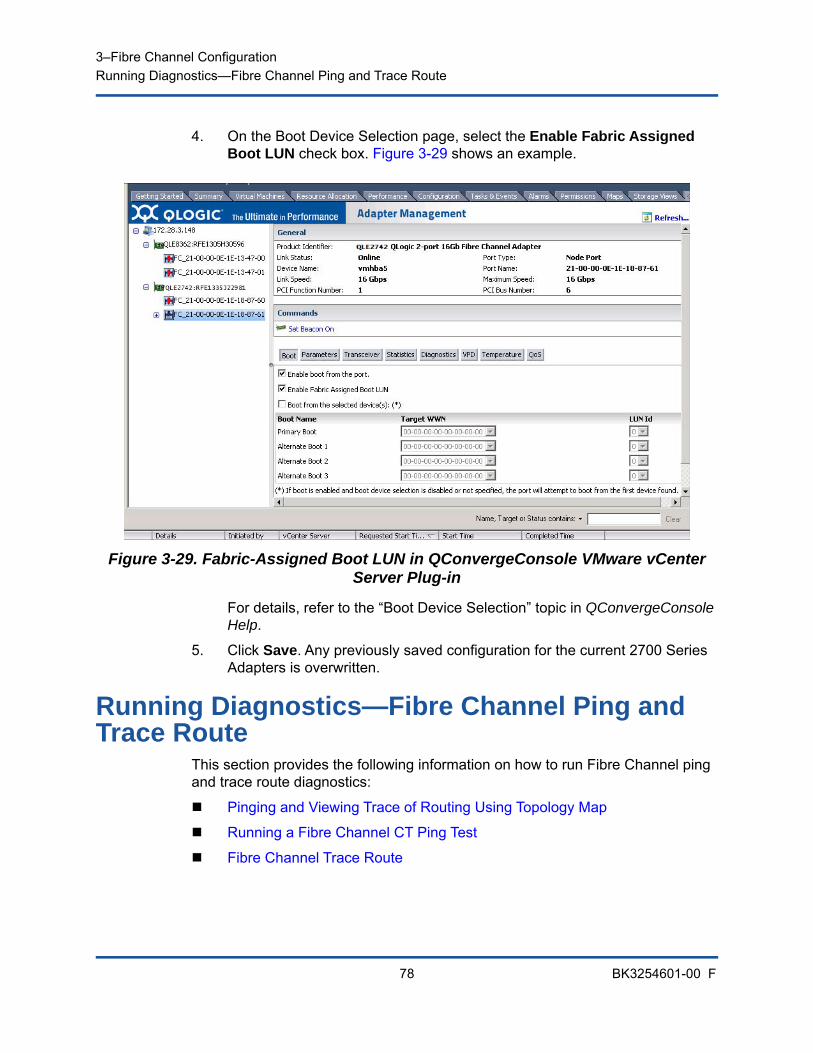
3–Fibre Channel ConfigurationRunning Diagnostics—Fibre Channel Ping and Trace Route
78 BK3254601-00 F
4. On the Boot Device Selection page, select the Enable Fabric Assigned Boot LUN check box. Figure 3-29 shows an example.
Figure 3-29. Fabric-Assigned Boot LUN in QConvergeConsole VMware vCenter Server Plug-in
For details, refer to the “Boot Device Selection” topic in QConvergeConsole Help.
5. Click Save. Any previously saved configuration for the current 2700 Series Adapters is overwritten.
Running Diagnostics—Fibre Channel Ping and Trace Route
This section provides the following information on how to run Fibre Channel ping and trace route diagnostics:
Pinging and Viewing Trace of Routing Using Topology Map
Running a Fibre Channel CT Ping Test
Fibre Channel Trace Route
3–Fibre Channel ConfigurationRunning Diagnostics—Fibre Channel Ping and Trace Route
79 BK3254601-00 F
Pinging and Viewing Trace of Routing Using Topology MapThe QConvergeConsole GUI topology map uses the common transport (CT) layer to enable the adapter’s initiator port to ping or run a trace route that will navigate across the environment through multiple ports of the switch or switches and to the target.
Table 3-8 compares the differences between the Ping Test, CT Ping Test, and the CT FTR Tests.
Supported configurations for Fibre Channel ping and trace route include:
QLogic 2700 Series Adapters
Brocade Switches with Based Fabric OS® (FOS) v6.0.0a
Running a Fibre Channel CT Ping TestYou can run a Fibre Channel CT ping test from QConvergeConsole GUI, QConvergeConsole CLI, or the QConvergeConsole VMware plug-ins, as described in this section.
Running a Fibre Channel CT Ping from QConvergeConsole GUI
To run a Fibre Channel CT ping test from QConvergeConsole GUI:
1. In the QConvergeConsole GUI left pane, click the Host tab.
2. On the Host page, expand the adapter node and then select a port.
3. In the content pane on the right, click the Diagnostics tab.
Table 3-8. Ping Test, CT Ping Test, and CT FTR Test
Ping Test CT Ping Test CT FTR Test
SCSI layer ping CT or Fibre Channel ping CT or Fibre Channel trace route
Uses SCSI inquiry command Uses echo through an external link
Requires scan of physical topology
Can operate on any SCSI device
Can operate with all Fibre Chan-nel devices that support CT or an external link
Can operate with all devices that are connected through a port that supports CT or an external link
NOTE
The switch and the Fibre Channel end device must both support the Fibre Channel ping and trace route feature. See Table 3-10 on page 95 for the supported Fibre Channel software version.
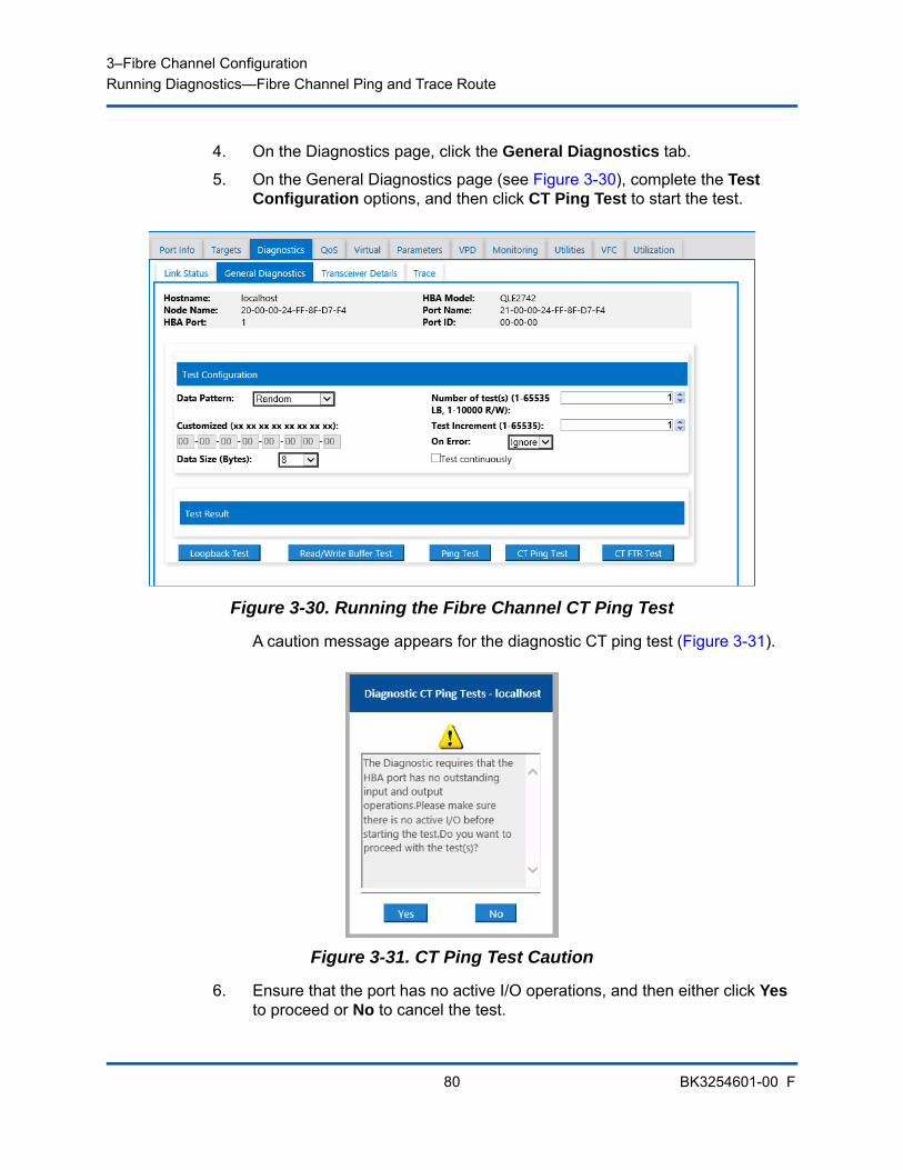
3–Fibre Channel ConfigurationRunning Diagnostics—Fibre Channel Ping and Trace Route
80 BK3254601-00 F
4. On the Diagnostics page, click the General Diagnostics tab.
5. On the General Diagnostics page (see Figure 3-30), complete the Test Configuration options, and then click CT Ping Test to start the test.
Figure 3-30. Running the Fibre Channel CT Ping Test
A caution message appears for the diagnostic CT ping test (Figure 3-31).
Figure 3-31. CT Ping Test Caution
6. Ensure that the port has no active I/O operations, and then either click Yes to proceed or No to cancel the test.
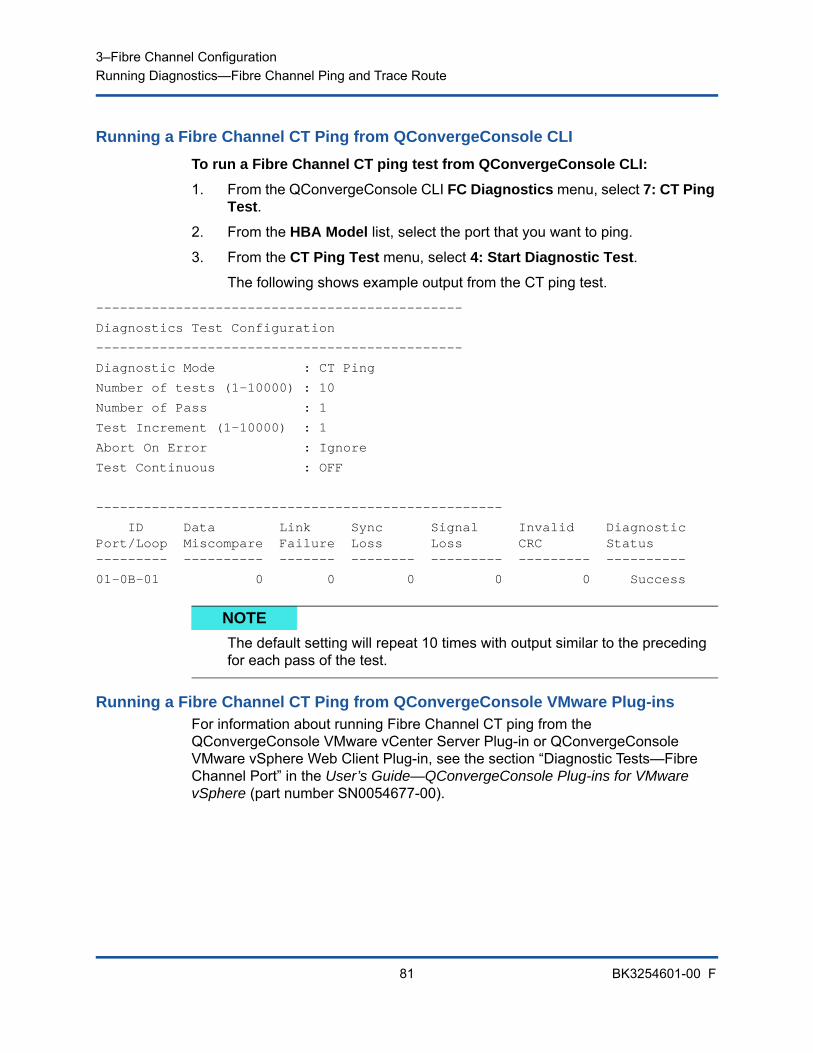
3–Fibre Channel ConfigurationRunning Diagnostics—Fibre Channel Ping and Trace Route
81 BK3254601-00 F
Running a Fibre Channel CT Ping from QConvergeConsole CLI
To run a Fibre Channel CT ping test from QConvergeConsole CLI:
1. From the QConvergeConsole CLI FC Diagnostics menu, select 7: CT Ping Test.
2. From the HBA Model list, select the port that you want to ping.
3. From the CT Ping Test menu, select 4: Start Diagnostic Test.
The following shows example output from the CT ping test.
----------------------------------------------
Diagnostics Test Configuration
----------------------------------------------
Diagnostic Mode : CT Ping
Number of tests (1-10000) : 10
Number of Pass : 1
Test Increment (1-10000) : 1
Abort On Error : Ignore
Test Continuous : OFF
---------------------------------------------------
ID Data Link Sync Signal Invalid DiagnosticPort/Loop Miscompare Failure Loss Loss CRC Status--------- ---------- ------- -------- --------- --------- ----------
01-0B-01 0 0 0 0 0 Success
Running a Fibre Channel CT Ping from QConvergeConsole VMware Plug-insFor information about running Fibre Channel CT ping from the QConvergeConsole VMware vCenter Server Plug-in or QConvergeConsole VMware vSphere Web Client Plug-in, see the section “Diagnostic Tests—Fibre Channel Port” in the User’s Guide—QConvergeConsole Plug-ins for VMware vSphere (part number SN0054677-00).
NOTE
The default setting will repeat 10 times with output similar to the preceding for each pass of the test.
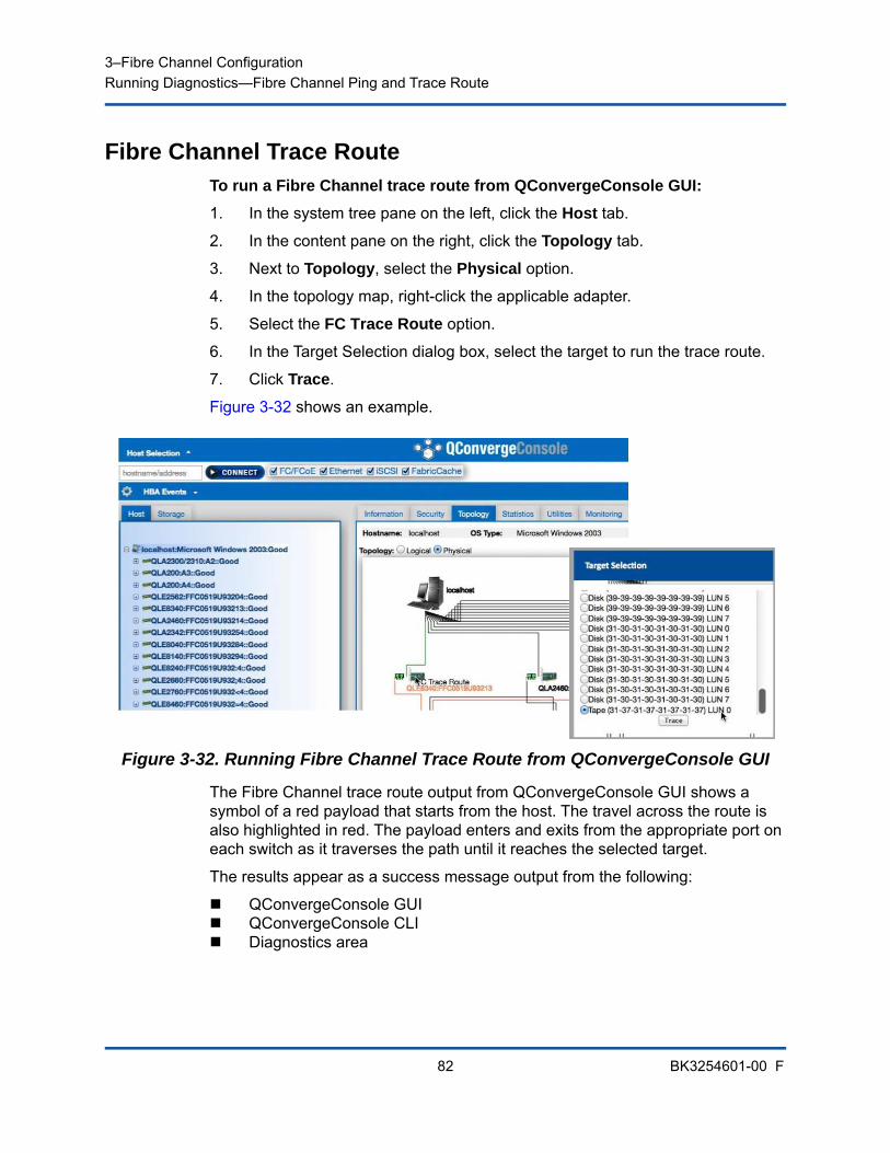
3–Fibre Channel ConfigurationRunning Diagnostics—Fibre Channel Ping and Trace Route
82 BK3254601-00 F
Fibre Channel Trace RouteTo run a Fibre Channel trace route from QConvergeConsole GUI:
1. In the system tree pane on the left, click the Host tab.
2. In the content pane on the right, click the Topology tab.
3. Next to Topology, select the Physical option.
4. In the topology map, right-click the applicable adapter.
5. Select the FC Trace Route option.
6. In the Target Selection dialog box, select the target to run the trace route.
7. Click Trace.
Figure 3-32 shows an example.
Figure 3-32. Running Fibre Channel Trace Route from QConvergeConsole GUI
The Fibre Channel trace route output from QConvergeConsole GUI shows a symbol of a red payload that starts from the host. The travel across the route is also highlighted in red. The payload enters and exits from the appropriate port on each switch as it traverses the path until it reaches the selected target.
The results appear as a success message output from the following:
QConvergeConsole GUI QConvergeConsole CLI Diagnostics area

3–Fibre Channel ConfigurationConfiguring CS_CTL QoS
83 BK3254601-00 F
For information about using Fibre Channel trace route in QConvergeConsole VMware vCenter Server Plug-in or QConvergeConsole VMware vSphere Web Client Plug-in, see the section “Diagnostic Tests—Fibre Channel Port” in the User’s Guide—QConvergeConsole Plug-ins for VMware vSphere (part number SN0054677-00).
Configuring CS_CTL QoS
This section provides the following information on class-specific control (CS_CTL) quality of service (QoS):
CS_CTL QoS Features
Enabling CS_CTL QoS Mode for the Initiator and Target Ports
Verifying and Confirming CS_CTL Mode Setup for Each Port
Creating a Virtual Port from the Adapter’s Port in QConvergeConsole GUI
Setting the QoS Priority Level for a Virtual Port in QConvergeConsole GUI
CS_CTL QoS FeaturesThe following highlights some of the features of the CS_CTL QoS:
Traffic priority classification for QLogic Gen 6 Fibre Channel SAN. QoS at the packet level is realized by using the CS_CTL field, which is specified in the FC-FS-2 specification. QoS allows one to prioritize frames between a host and target, depending on the value of the CS_CTL field in the FC Frame header.
Extending QoS from the fabric to the host
Enables QLogic Fibre Channel users to rapidly scale server virtualization without compromising service-level agreements
Benefits for both physical and virtual server deployments
NOTE
You can also execute the CT FTR test.
NOTE
For information about end-to-end CS_CTL QoS, see “Configuring End-to-End CS_CTL QoS” on page 87.
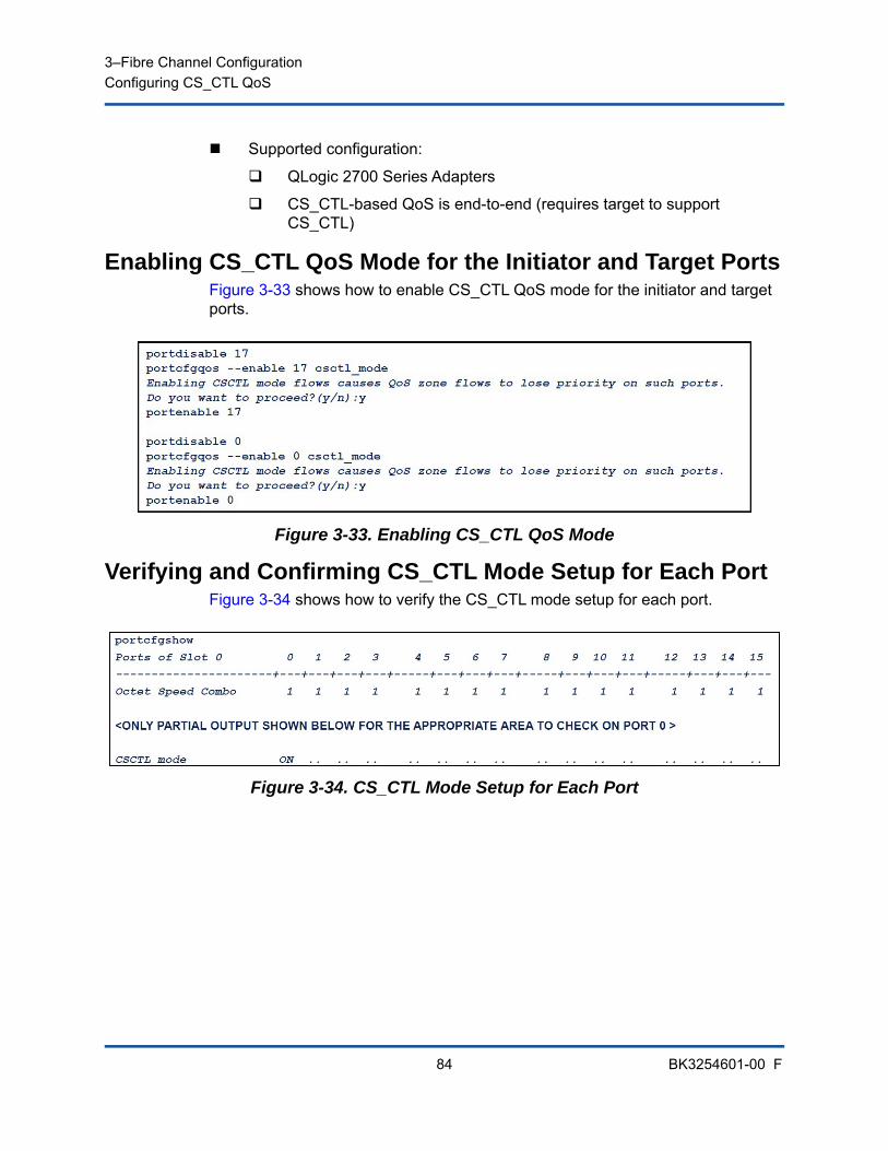
3–Fibre Channel ConfigurationConfiguring CS_CTL QoS
84 BK3254601-00 F
Supported configuration:
QLogic 2700 Series Adapters
CS_CTL-based QoS is end-to-end (requires target to support CS_CTL)
Enabling CS_CTL QoS Mode for the Initiator and Target PortsFigure 3-33 shows how to enable CS_CTL QoS mode for the initiator and target ports.
Figure 3-33. Enabling CS_CTL QoS Mode
Verifying and Confirming CS_CTL Mode Setup for Each PortFigure 3-34 shows how to verify the CS_CTL mode setup for each port.
Figure 3-34. CS_CTL Mode Setup for Each Port
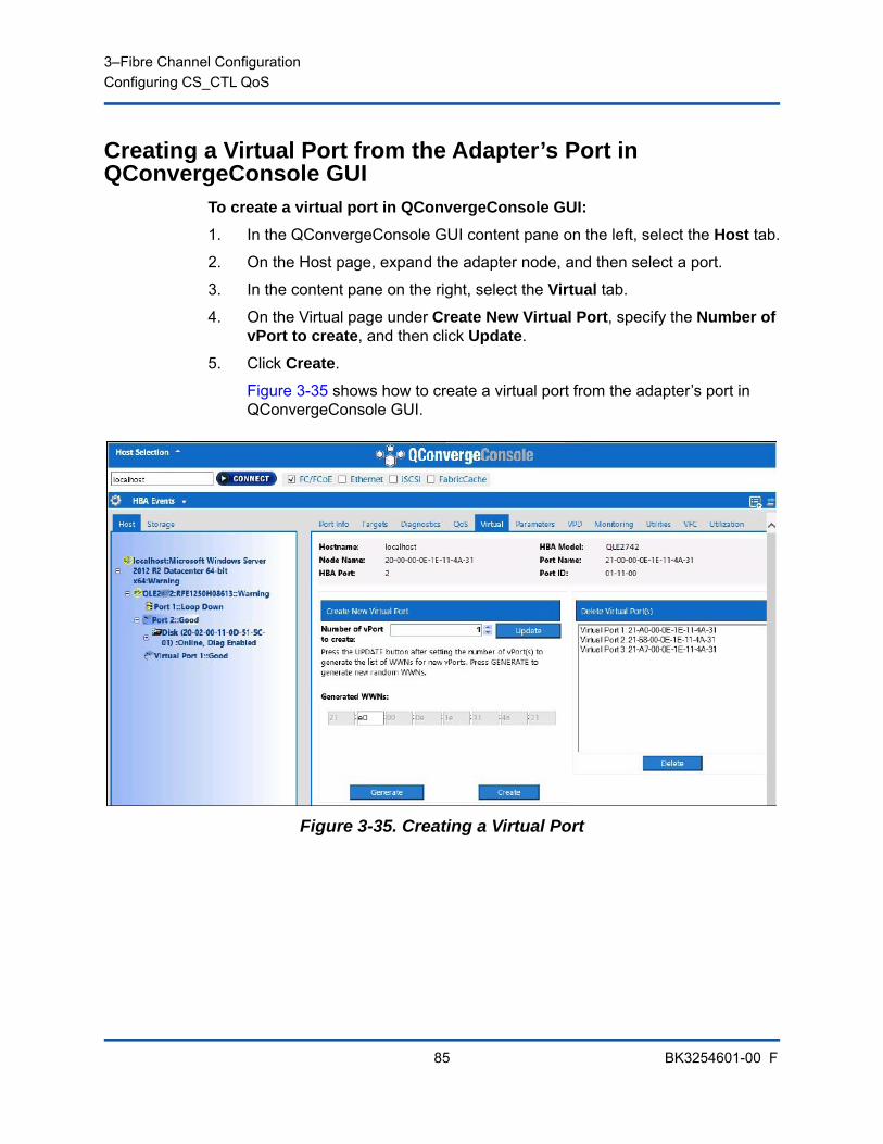
3–Fibre Channel ConfigurationConfiguring CS_CTL QoS
85 BK3254601-00 F
Creating a Virtual Port from the Adapter’s Port in QConvergeConsole GUI
To create a virtual port in QConvergeConsole GUI:
1. In the QConvergeConsole GUI content pane on the left, select the Host tab.
2. On the Host page, expand the adapter node, and then select a port.
3. In the content pane on the right, select the Virtual tab.
4. On the Virtual page under Create New Virtual Port, specify the Number of vPort to create, and then click Update.
5. Click Create.
Figure 3-35 shows how to create a virtual port from the adapter’s port in QConvergeConsole GUI.
Figure 3-35. Creating a Virtual Port
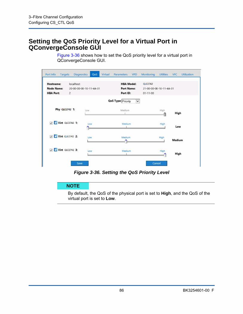
3–Fibre Channel ConfigurationConfiguring CS_CTL QoS
86 BK3254601-00 F
Setting the QoS Priority Level for a Virtual Port in QConvergeConsole GUI
Figure 3-36 shows how to set the QoS priority level for a virtual port in QConvergeConsole GUI.
Figure 3-36. Setting the QoS Priority Level
NOTE
By default, the QoS of the physical port is set to High, and the QoS of the virtual port is set to Low.
3–Fibre Channel ConfigurationConfiguring End-to-End CS_CTL QoS
87 BK3254601-00 F
Configuring End-to-End CS_CTL QoS
QLogic’s class specific control (CS_CTL) QoS implementation is an end-to-end solution, encompassing the initiator (2700 Series Adapters), the switches, and the target (storage). The 2700 Series Adapter stamps the priority value (high, medium, low) in the CS_CTL field of the Fibre Channel frame. All three entities (initiator, switch, and target) honor this priority value at their respective levels.
Therefore, when all three entities support QoS (and it is enabled on the switch and the target), a default priority value is populated in all FCP_CMND, FCP_DATA, FCP_XFER_RDY, FCP_RSP, and FCP_CONFIRM frames.
The following sections describe how to configure end-to-end CS_CTL QoS and change the default priority levels:
Configuring CS_CTL QoS on the Switch
Configuring CS_CTL QoS on the Storage Device
Changing the QoS Priority Levels
Configuring CS_CTL QoS on the SwitchTo enable CS_STL QoS on the Brocade SW6510 switch:
1. From the switch, issue the following command:
root> configurechassis
Configure...
2. A list of attributes appear one at a time. After either accepting the default or entering a different value, the next attribute appears.
Press ENTER to accept the default for cfgload attributes, Custom attributes, and system attributes.
Type y for fos attributes.
NOTE
For information about CS_CTL QoS that is not end-to-end, see “Configuring CS_CTL QoS” on page 83.
NOTEi
QoS must be supported by both the switch and target devices.At the time of publication, CS_CTL QoS has been tested only on the Brocade SW6510 switch with Fabric OS (FOS) version 7.3.0a.
3–Fibre Channel ConfigurationConfiguring End-to-End CS_CTL QoS
88 BK3254601-00 F
Type 1 for CSCTL QoS Mode.
For example:
cfgload attributes (yes, y, no, n): [no]
Custom attributes (yes, y, no, n): [no]
system attributes (yes, y, no, n): [no]
fos attributes (yes, y, no, n): [no] y
CSCTL QoS Mode (0 = default; 1 = auto mode): (0..1) [0] 1
3. Reboot the switch.
4. To verify that CS_CTL QoS is enabled, issue the following command:
root> configshow -all | grep fos.csctlMode
This command should return the following response:
fos.csctlMode:1
5. To enable QoS on a switch-port basis, issue the following command:
portcfgqos --enable [slot/]port csctl_mode
Configuring CS_CTL QoS on the Storage DeviceSee your device’s user guide for QoS configuration instructions.
Changing the QoS Priority LevelsThe QoS priority levels are set in the 2700 Series Adapters vPorts. The Windows and VMware adapter drivers assign default vPort priority levels. The following sections describe how to change the default vPort priority levels in Windows and VMware ESXi systems.
Changing the Priority Levels in WindowsTo change the vPort priority levels in Windows, you must first assign the vPorts, and then change the priority levels. Both procedures can be accomplished using either QConvergeConsole GUI or interactive QConvergeConsole CLI, as described in the following sections.
For more detailed information, see the QConvergeConsole Help and the User’s Guide—QConvergeConsole CLI (part number SN0054667-00).

3–Fibre Channel ConfigurationConfiguring End-to-End CS_CTL QoS
89 BK3254601-00 F
Creating a Vport
To create a vPort in QConvergeConsole GUI:
1. In the QConvergeConsole GUI left pane, connect to the host that has the 2700 Series Adapters where you want to create the vPorts.
2. Expand the host in the left pane by clicking the plus sign (+).
3. Locate and expand the 2700 Series Adapters where you want to create the vPorts.
4. In the right pane, click the Virtual tab.
5. Enter a valid value for the Number of vPort to create option, and then click Update.
6. To create the vPorts, click Create.
Figure 3-37 shows an example.
Figure 3-37. Creating vPorts in QConvergeConsole GUI
To create a vPort in interactive QConvergeConsole CLI:
1. On the Main Menu, select Adapter Configuration.
2. On the Adapter Type Selection menu, select Virtual Ports (NPIV).
3. On the Virtual Ports menu, select Adapter Port.
4. On the Adapter Port menu, select Create vPorts.
5. On the Create vPorts menu, select Generate.
6. To create the vPorts, select Commit.
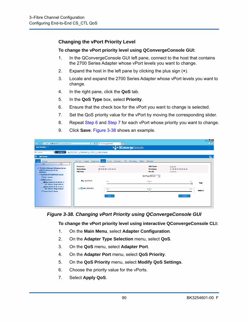
3–Fibre Channel ConfigurationConfiguring End-to-End CS_CTL QoS
90 BK3254601-00 F
Changing the vPort Priority Level
To change the vPort priority level using QConvergeConsole GUI:
1. In the QConvergeConsole GUI left pane, connect to the host that contains the 2700 Series Adapter whose vPort levels you want to change.
2. Expand the host in the left pane by clicking the plus sign (+).
3. Locate and expand the 2700 Series Adapter whose vPort levels you want to change.
4. In the right pane, click the QoS tab.
5. In the QoS Type box, select Priority.
6. Ensure that the check box for the vPort you want to change is selected.
7. Set the QoS priority value for the vPort by moving the corresponding slider.
8. Repeat Step 6 and Step 7 for each vPort whose priority you want to change.
9. Click Save. Figure 3-38 shows an example.
Figure 3-38. Changing vPort Priority using QConvergeConsole GUI
To change the vPort priority level using interactive QConvergeConsole CLI:
1. On the Main Menu, select Adapter Configuration.
2. On the Adapter Type Selection menu, select QoS.
3. On the QoS menu, select Adapter Port.
4. On the Adapter Port menu, select QoS Priority.
5. On the QoS Priority menu, select Modify QoS Settings.
6. Choose the priority value for the vPorts.
7. Select Apply QoS.
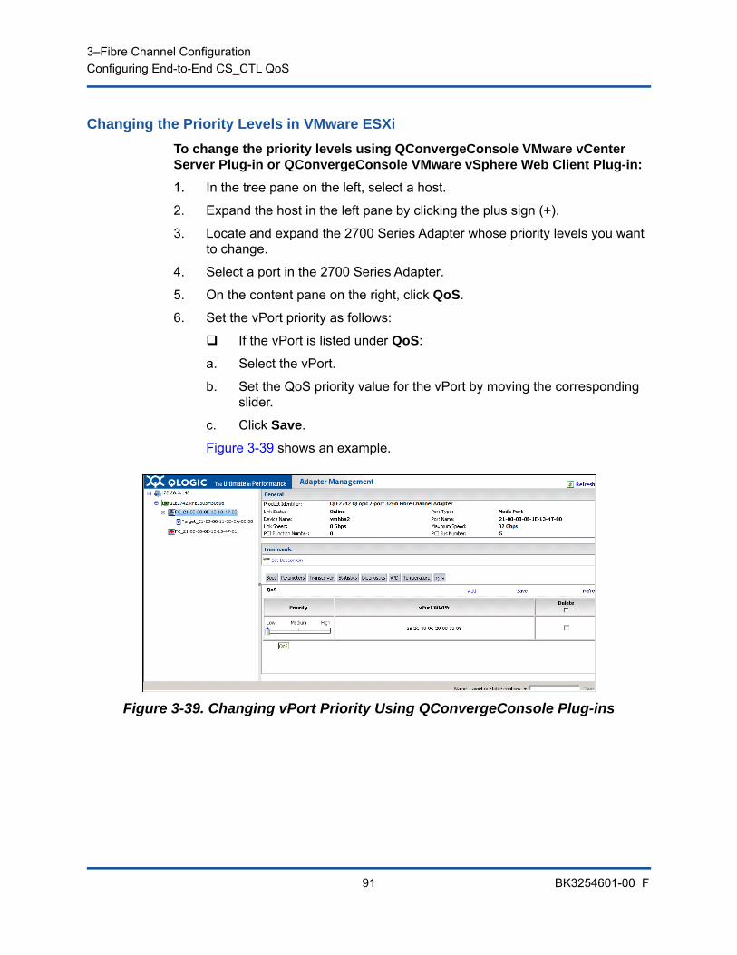
3–Fibre Channel ConfigurationConfiguring End-to-End CS_CTL QoS
91 BK3254601-00 F
Changing the Priority Levels in VMware ESXi
To change the priority levels using QConvergeConsole VMware vCenter Server Plug-in or QConvergeConsole VMware vSphere Web Client Plug-in:
1. In the tree pane on the left, select a host.
2. Expand the host in the left pane by clicking the plus sign (+).
3. Locate and expand the 2700 Series Adapter whose priority levels you want to change.
4. Select a port in the 2700 Series Adapter.
5. On the content pane on the right, click QoS.
6. Set the vPort priority as follows:
If the vPort is listed under QoS:
a. Select the vPort.
b. Set the QoS priority value for the vPort by moving the corresponding slider.
c. Click Save.
Figure 3-39 shows an example.
Figure 3-39. Changing vPort Priority Using QConvergeConsole Plug-ins
3–Fibre Channel ConfigurationConfiguring FDMI
92 BK3254601-00 F
If vPort is not listed under QoS:
a. Under QoS, click Add.
b. Set the QoS priority value by moving the corresponding slider.
c. Enter the vPort WWPN.
d. Click Save.
7. Click Refresh to see the new QoS settings.
To remove a vPort priority:
1. Under QoS, locate the vPort whose priority you want to remove.
2. Do one of the following:
Select the Delete check box of the vPort you want to remove.
Select the Delete check box in the header to select or clear all of the vPorts.
3. Click Save.
Configuring FDMIThe fabric device management interface (FDMI) enables the centralized management of devices such as host adapters. Supported configuration for FDMI:
QLogic 2700 Series Adapters
Brocade 16G and 32G switches with Fabric OS (FOS) v7.3 or later
This section provides the following information on the FDMI:
Brocade Switch FOS CLI
Brocade Fabric Features
FDMI Enhancements Support
NOTEi
Results can be viewed from Switch CLI. If the Fibre Channel switch does not support FDMI-2, it falls back to FDMI-1 support.
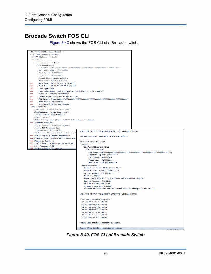
3–Fibre Channel ConfigurationConfiguring FDMI
93 BK3254601-00 F
Brocade Switch FOS CLIFigure 3-40 shows the FOS CLI of a Brocade switch.
Figure 3-40. FOS CLI of Brocade Switch

3–Fibre Channel ConfigurationConfiguring FDMI
94 BK3254601-00 F
Brocade Fabric FeaturesTable 3-9 shows the default configuration for Brocade Fibre Channel fabric features.
.
Table 3-9. Brocade Fibre Channel Fabric Features—Default Configuration
Feature Description Management Tools Default Configuration
D_Port Diagnostics port support
N/A Diagnostic test; run from switch. Nothing to config-ure on adapter.
FA-PWWN Fabric-assigned port world wide name
QConvergeConsole GUIQConvergeConsole CLIQConvergeConsole VMware vCenter Server Plug-in
Disabled by default on adapter. Must be enabled in NVRAM.
F-BLD Fabric-based boot LUN discovery
QConvergeConsole GUIQConvergeConsole CLIQConvergeConsole VMware vCenter Server Plug-in
No default setting. Requires configuration on adapter.
FC Ping Ping a Fibre Channel N_Port or end device
QConvergeConsole GUIQConvergeConsole CLIQConvergeConsole VMware vCenter Server Plug-in
Diagnostic test; nothing to configure.
FC Trace Route Obtains the path infor-mation between two F_Ports from the Fabric Configuration Server
QConvergeConsole GUIQConvergeConsole CLIQConvergeConsole VMware vCenter Server Plug-in
Diagnostic test; nothing to configure.
QoS CS_CTL Prioritize frames depending on the value of the CS_CTL field in the FC Frame header
QConvergeConsole GUIQConvergeConsole CLIQConvergeConsole VMware vCenter Server Plug-in
By default, QoS of the physical port is set to High.
FDMI Enhancements
FDMI attributes N/A Nothing to configure on adapter.

3–Fibre Channel ConfigurationConfiguring FDMI
95 BK3254601-00 F
Table 3-10 lists the Dell software version of the Fibre Channel fabric features.
FDMI Enhancements SupportFDMI enables the management of devices such as host adapters. Enabling additional attributes using FDMI provides you with detailed information about the QLogic adapters through a centralized management entity such as the Fibre Channel fabric switches.
To verify the additional QLogic adapter attributes registered on the Brocade switch, issue the fdmishow command on Brocade Fibre Channel switches to confirm that all the requested attributes are displayed in the switch. For details, see the Brocade switch documentation.
The following shows sample output of the fdmishow command.
Port attributes:
"Device Name: QLogic Adapter"
"Node Name: 20:00:00:0e:1e:80:af:80"
"Port Name: 21:00:00:0e:1e:80:af:78"
"Port Type: 0x5"
"Port Symbolic Name: QLE8362 FW:v7.04.00 DVR:v9.1.12.20 Alpha 2"
"Class of Service: 0x00000008"
"Fabric Name: 10:00:00:05:33:8f:1a:49"
"FC4 Active Type: 0x000001000000000000000000000000000000000000000000000000000"
"Port State: 0x00000002"
"Discovered Ports: 0x00000000"
Table 3-10. Fibre Channel Fabric Features, Software Version
Component Dell Software Version
Firmware v7.04.00
Windows Driver v9.1.12.21
ESXi Driver ESXi 6.0 U2: v2.1.10.0
Linux Driver v8.07.00.16
QConvergeConsole GUI v5.1.0.213
QConvergeConsole CLI v1.1.03-29
3–Fibre Channel ConfigurationEnabling QLogic Forward Error Correction
96 BK3254601-00 F
HBA attributes:
"OS Name and Version: Windows Server 2012 R2 Datacenter Evaluation for Intel6 4"
"Max CT Payload Length: 0x00000800"
"Symbolic Name: QLE8362 FW:v7.04.00 DVR:v9.1.12.20 Alpha 2"
"Number of Ports: 1"
"Fabric Name: 10:00:00:05:33:8f:1a:43"
"Bios Version: 3.26"
"Vendor Identifier: QLOGIC"
Enabling QLogic Forward Error CorrectionQConvergeConsole supports the forward error correction (FEC) feature, which is a correction technique used for high-speed telecommunications devices to control errors in data transmission over unreliable or noisy communication channels.
FEC is mandatory when operating at 32Gb line rate. Gen 6 32Gb-capable adapters are required to support it, and FEC is automatically enabled when operating at 32G. If the 32G-capable adapter is operating at 16G, enabling FEC is optional, just as it is on QLE269x-DEL adapters.
NOTE
The switch and the Fibre Channel end device must both support the FEC feature. See Table 3-10 on page 95 for the supported Fibre Channel software version.
3–Fibre Channel ConfigurationEnabling QLogic Forward Error Correction
97 BK3254601-00 F
FEC Process OverviewThe following highlights how the FEC process works between the transmitting and receiving device:
1. Transmitter Device:
a. Takes the incoming data stream.
b. Inserts a redundant amount of parity bits of information on the data stream.
c. Sends the data stream.
2. Receiving Device:
a. Receives the data stream.
b. Checks for missing or corrupt data:
If there are no corrupt or missing bits of information, the receiving device proceeds with normal process.
If there are corrupt or missing bits of information, the receiving device reconstructs the original data by using pieces of the original data stream (that are still intact) and combining those with the parity bits of information.
NOTEi
Instead of having to request retransmission of the entire data frame, the receiving device can recreate or reconstruct the data stream itself. This process prevents multiple CRC errors from being triggered and causing application performance issues.
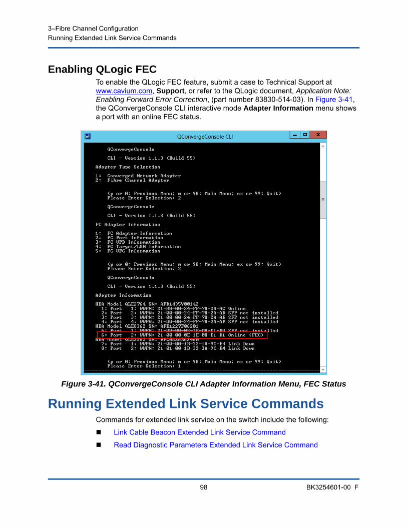
3–Fibre Channel ConfigurationRunning Extended Link Service Commands
98 BK3254601-00 F
Enabling QLogic FECTo enable the QLogic FEC feature, submit a case to Technical Support at www.cavium.com, Support, or refer to the QLogic document, Application Note: Enabling Forward Error Correction, (part number 83830-514-03). In Figure 3-41, the QConvergeConsole CLI interactive mode Adapter Information menu shows a port with an online FEC status.
Figure 3-41. QConvergeConsole CLI Adapter Information Menu, FEC Status
Running Extended Link Service CommandsCommands for extended link service on the switch include the following:
Link Cable Beacon Extended Link Service Command
Read Diagnostic Parameters Extended Link Service Command
3–Fibre Channel ConfigurationRunning Extended Link Service Commands
99 BK3254601-00 F
Link Cable Beacon Extended Link Service Command
The link cable beacon (LCB) extended link service command locates the corresponding ends of a cable by flashing the specific LEDs on the corresponding ports of a link. The LCB command can also be sent through a Brocade switch using the following commands, which show examples of enabling, disabling, or verifying the LCB:
SW6505:admin> portpeerbeacon --enable 12
SW6505:admin> portpeerbeacon --show -all
portPeerBeacon is enabled on port :12
SW6505:admin> portpeerbeacon --disable 12
Read Diagnostic Parameters Extended Link Service Command
The following example shows the read diagnostic parameters extended link service (RDP ELS) command output for Port 13 on a Brocade 16G switch:
SW6505:admin> sfpshow 13 -link -force
Identifier: 3 SFP
Connector: 7 LC
Transceiver: 7004404000000000 8,16,32_Gbps M5 sw Short_dist
Encoding: 6 64B66B
Baud Rate: 140 (units 100 megabaud)
Length 9u: 0 (units km)
Length 9u: 0 (units 100 meters)
Length 50u (OM2): 3 (units 10 meters)
Length 50u (OM3): 0 (units 10 meters)
Length 62.5u:0 (units 10 meters)
Length Cu: 0 (units 1 meter)
Vendor Name: HP-F BROCADE
Vendor OUI: 00:05:1e
Vendor PN: QK724A
NOTE
Run the LCB test only from a switch with FOS version 7.4.x or later.
NOTE
You must run the RDP test from a switch with FOS version 7.4.x or later.
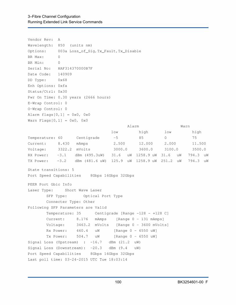
3–Fibre Channel ConfigurationRunning Extended Link Service Commands
100 BK3254601-00 F
Vendor Rev: A
Wavelength: 850 (units nm)
Options: 003a Loss_of_Sig,Tx_Fault,Tx_Disable
BR Max: 0
BR Min: 0
Serial No: HAF314370000B7F
Date Code: 140909
DD Type: 0x68
Enh Options: 0xfa
Status/Ctrl: 0x30
Pwr On Time: 0.30 years (2666 hours)
E-Wrap Control: 0
O-Wrap Control: 0
Alarm flags[0,1] = 0x0, 0x0
Warn Flags[0,1] = 0x0, 0x0
Alarm Warn
low high low high
Temperature: 60 Centigrade -5 85 0 75
Current: 8.430 mAmps 2.500 12.000 2.000 11.500
Voltage: 3322.2 mVolts 3000.0 3600.0 3100.0 3500.0
RX Power: -3.1 dBm (495.3uW) 31.6 uW 1258.9 uW 31.6 uW 794.3 uW
TX Power: -3.2 dBm (481.6 uW) 125.9 uW 1258.9 uW 251.2 uW 794.3 uW
State transitions: 5
Port Speed Capabilities 8Gbps 16Gbps 32Gbps
PEER Port Gbic Info
Laser Type: Short Wave Laser
SFP Type: Optical Port Type
Connecter Type: Other
Following SFP Parameters are Valid
Temperature: 35 Centigrade [Range -128 - +128 C]
Current: 8.176 mAmps [Range 0 - 131 mAmps]
Voltage: 3463.2 mVolts [Range 0 - 3600 mVolts]
Rx Power: 460.4 uW [Range 0 - 6550 uW]
Tx Power: 504.7 uW [Range 0 - 6550 uW]
Signal Loss (Upstream) : -16.7 dBm (21.2 uW)
Signal Loss (Downstream): -20.3 dBm (9.4 uW)
Port Speed Capabilities 8Gbps 16Gbps 32Gbps
Last poll time: 03-24-2015 UTC Tue 18:03:14
101 BK3254601-00 F
A Troubleshooting
This appendix provides information about Fibre Channel diagnostics and a Fibre Channel troubleshooting diagram, including:
Fibre Channel Diagnostics
“Fibre Channel Troubleshooting Diagram” on page 104
“Troubleshooting with a Diagnostic Port (D_Port)” on page 105
Fibre Channel DiagnosticsTroubleshooting with Fibre Channel diagnostics include:
Fibre Channel Diagnostics Using QConvergeConsole GUI
Fibre Channel Diagnostics Using Interactive QConvergeConsole CLI
Fibre Channel Diagnostics Using Noninteractive QConvergeConsole CLI
Fibre Channel Diagnostics Using QConvergeConsole GUIQConvergeConsole GUI supports the internal and external loopback, read/write buffer, and beacon on/off diagnostic tests for Fibre Channel ports.
To set the loopback or read/write buffer test parameters:
1. In the QConvergeConsole system tree, select the adapter port.
2. In the content pane on the right, click the Diagnostics tab, and then click the General Diagnostics tab.
3. From the Data Pattern list, do one of the following:
Select a data byte or compliant jitter pattern.
Click Customized to specify your own eight-byte pattern. Enter the data in hexadecimal format (0–FF) into the eight Customized boxes.
Click Random to randomly generate an eight-byte data pattern.
The data size sets the number of bytes transferred per test per iteration when the test is run.

A–TroubleshootingFibre Channel Diagnostics
102 BK3254601-00 F
4. From the Data Size list, click the number of bytes to transfer.
Valid values are 8, 16, 32, 64, 128, 256, 512, 1024 and 2048. For Linux operating systems only, you can select data size values from 2048, 4096, 8192 up to 65535 (2K bytes to 64K bytes).
5. To set the test frequency, do one of the following:
In the Number of Tests box, type or select the number of tests you want to run. Testing stops when the passes complete. The valid range is between 1 and 65535 for loopback tests and between 1 and 10,000 for read/write buffer tests.
Select the Test Continuously check box. You determine when testing stops.
6. In the On Error box, click one of the following to determine how errors are handled. This selection applies whether you entered the Number of Tests or selected Test Continuously.
Ignore on Error—Ignores errors and continues the test sequence.
Stop on Error—Stops the test sequence once an error is encountered.
Loop on Error—Uses the same data pattern and test until the failure is cleared.
7. In the Test Increment box, type or select the number of passes you want to run before the test stops.
The valid range is between 1 and 10,000 and must be less than or equal to the value in the Number of Tests box (see Step 5). For example, if the Number of Tests box contains 100 and the Test Increment box contains 15, 100 tests are run in seven passes. The first six passes run 15 tests each; the seventh pass runs 10 tests: (6 × 15) + 10 = 100.
To run the loopback or read/write buffer test:
1. Click the Loopback Test or Read/Write Buffer Test button.
The diagnostic tests warning appears.
2. Click Yes if there are no I/Os active and you want to proceed with the test or click No to cancel the diagnostic test.
3. If you selected the loopback test, a dialog box allows you to select Internal Loopback or External Loopback. Click the appropriate test and then click OK.
4. If you selected Yes in Step 2, a dialog box appears with the data pattern generated. Click Stop when you want to end the test.
A–TroubleshootingFibre Channel Diagnostics
103 BK3254601-00 F
To run the beacon on/off test:
1. In the QConvergeConsole GUI main window, click an adapter port in the system tree pane on the left.
2. In the content pane on the right, click the Port Info tab.
3. On the Port Info page, click Beacon On to run the test. To end the test, click Beacon Off.
For more information, refer to the topic about performing diagnostics in the QConvergeConsole Help.
Fibre Channel Diagnostics Using Interactive QConvergeConsole CLI
To run the loopback test, read/write buffer test, or beacon test:
1. On the Main Menu, select 4: Adapter Diagnostics.
2. On the Fibre Channel Diagnostics menu, select the test type to run:
1: Loopback Test to run the loopback test.
2: Read Write Buffer Test to run the read/write buffer test.
3: Beacon Test to run the beacon test.
4: Transceiver Diagnostics Monitoring Interface (DMI) to view the transceiver diagnostics information.
For more information, refer to the section about the Fibre Channel interactive commands in the User’s Guide—QConvergeConsole CLI (part number SN0054667-00).
Fibre Channel Diagnostics Using Noninteractive QConvergeConsole CLI
For information, refer to the section about the Fibre Channel noninteractive commands in the User’s Guide—QConvergeConsole CLI (part number SN0054667-00).
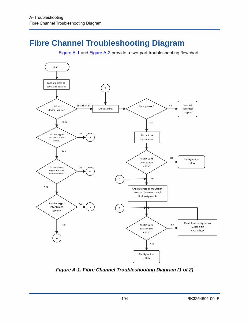
A–TroubleshootingFibre Channel Troubleshooting Diagram
104 BK3254601-00 F
Fibre Channel Troubleshooting DiagramFigure A-1 and Figure A-2 provide a two-part troubleshooting flowchart.
Figure A-1. Fibre Channel Troubleshooting Diagram (1 of 2)
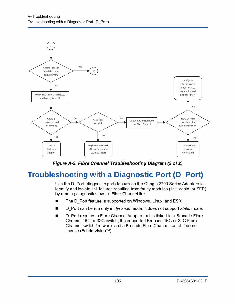
A–TroubleshootingTroubleshooting with a Diagnostic Port (D_Port)
105 BK3254601-00 F
Figure A-2. Fibre Channel Troubleshooting Diagram (2 of 2)
Troubleshooting with a Diagnostic Port (D_Port)Use the D_Port (diagnostic port) feature on the QLogic 2700 Series Adapters to identify and isolate link failures resulting from faulty modules (link, cable, or SFP) by running diagnostics over a Fibre Channel link.
The D_Port feature is supported on Windows, Linux, and ESXi.
D_Port can be run only in dynamic mode; it does not support static mode.
D_Port requires a Fibre Channel Adapter that is linked to a Brocade Fibre Channel 16G or 32G switch, the supported Brocade 16G or 32G Fibre Channel switch firmware, and a Brocade Fibre Channel switch feature license (Fabric Vision™).
No
Yes
Yes
No
No
Yes
3
Adapter can log into fabric and name server?
Verify that cable is connected and link lights are lit
Cable is connected and link lights lit?
Troubleshoot physical
connec on
Are op cs QLogic?
Fibre Channel switch set for
auto-nego a on?
Contact Technical Support
2
Yes
No
Replace op cs with QLogic op cs and return to “Start”
Check auto-nego a on on Fibre Channel
Co gure Fibre Channel
switch for auto-nego a on and return to “Start”
A–TroubleshootingTroubleshooting with a Diagnostic Port (D_Port)
106 BK3254601-00 F
Configure the diagnostic D_Port on the Brocade switch to dynamically allow a port to enter D_Port mode when a D_Port is configured on the switch end, and then return to operational mode when the test is completed. Also configure the switch to start and stop the diagnostic test on the adapter port. See the Brocade switch documentation for details.
When a switch port is enabled as a D_Port, the QLogic 2700 Series Adapter automatically runs the basic diagnostic test at both ends of the link. The Brocade switch then runs the following additional tests:
Electric loopback test Optical loopback test
QLogic recommends running D_Port tests on multipath configured boot from SAN/fabric-assigned boot LUN. Running D_Port tests on single path boot from SAN/fabric-assigned boot LUN may cause issues with OS stability in true boot from SAN environments.
The following sections describe how to configure and run D_Port mode from the Brocade Fibre Channel 16 switch, and how to verify D_Port mode from the QConvergeConsole utilities:
Configuring D_Port on a Brocade Fibre Channel 16G or 32G Switch
Checking D_Port Results from a Brocade Fibre Channel 16G or 32G Switch
Verifying D_Port Mode with QConvergeConsole GUI
Verifying D_Port Mode with Interactive QConvergeConsole CLI
Verifying D_Port Mode with Noninteractive QConvergeConsole CLI
Verifying D_Port Mode with QConvergeConsole Plug-ins
NOTE
All QLogic-branded 32GFC SFP+ transceivers can run D_Port tests. If you have a supported non-QLogic branded transceiver, ensure that it supports the optical wrap (OWrap) and electrical wrap (EWrap) capability that is required for D_Port.
A–TroubleshootingTroubleshooting with a Diagnostic Port (D_Port)
107 BK3254601-00 F
Configuring D_Port on a Brocade Fibre Channel 16G or 32G Switch
To enable D_Port diagnostic mode:
From the Brocade Fibre Channel 16G or 32G switch, issue the following commands:
# portdisable <port#>
# portcfgdport ––enable <port#>
# portenable <port#>
The D_Port test starts automatically.
To disable D_Port diagnostic mode:
From the Brocade Fibre Channel 16G or 32G switch, issue the following commands:
# portdisable <port_num>
# portcfgdport ––disable <port_num>
# portenable <port_num>
The D_Port test stops.
Checking D_Port Results from a Brocade Fibre Channel 16G or 32G Switch
To view the D_Port test results from a Brocade Fibre Channel 16G or 32G switch:
1. To get the port number, issue the switchshow command:
# switchshow
The following example output identifies port 17:
17 17 011100 id N16 Online FC D-Port Loopback->Port 17
2. Issue the portdporttest command as follows:
# portdporttest --show <port_num>
For example:
# portdporttest --show 17

A–TroubleshootingTroubleshooting with a Diagnostic Port (D_Port)
108 BK3254601-00 F
Following is an example output for this command.
portdporttest --show 17
D-Port Information:
===================
Port: 17
Remote WWPN: 21:00:00:0e:1e:11:4a:31
Mode: Automatic
No. of test frames: 1 Million
Test frame size: 1024 Bytes
FEC (enabled/option/active): Yes/No/No
CR (enabled/option/active): Yes/No/No
Start time: Thu Aug 14 01:45:37 2014
End time: Thu Aug 14 01:47:40 2014
Status: PASSED
==============================================================================
Test Start time Result EST(HH:MM:SS) Comments
==============================================================================
Electrical loopback 01:46:08 PASSED -------- ----------
Optical loopback 01:46:54 PASSED -------- ----------
Link traffic test -------- SKIPPED -------- ----------
==============================================================================
Roundtrip link latency: 157 nano-seconds
Estimated cable distance: 3 meters
Buffers required: 1 (for 2112 byte frames at 16Gbps speed)s
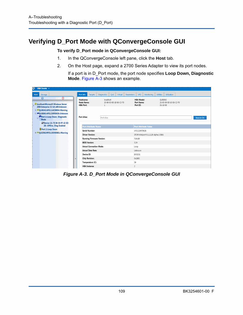
A–TroubleshootingTroubleshooting with a Diagnostic Port (D_Port)
109 BK3254601-00 F
Verifying D_Port Mode with QConvergeConsole GUITo verify D_Port mode in QConvergeConsole GUI:
1. In the QConvergeConsole left pane, click the Host tab.
2. On the Host page, expand a 2700 Series Adapter to view its port nodes.
If a port is in D_Port mode, the port node specifies Loop Down, Diagnostic Mode. Figure A-3 shows an example.
Figure A-3. D_Port Mode in QConvergeConsole GUI
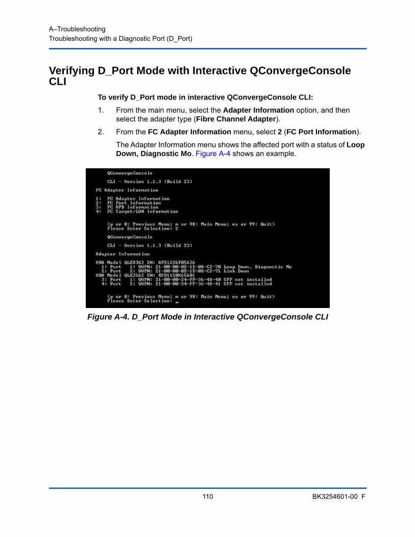
A–TroubleshootingTroubleshooting with a Diagnostic Port (D_Port)
110 BK3254601-00 F
Verifying D_Port Mode with Interactive QConvergeConsole CLI
To verify D_Port mode in interactive QConvergeConsole CLI:
1. From the main menu, select the Adapter Information option, and then select the adapter type (Fibre Channel Adapter).
2. From the FC Adapter Information menu, select 2 (FC Port Information).
The Adapter Information menu shows the affected port with a status of Loop Down, Diagnostic Mo. Figure A-4 shows an example.
Figure A-4. D_Port Mode in Interactive QConvergeConsole CLI
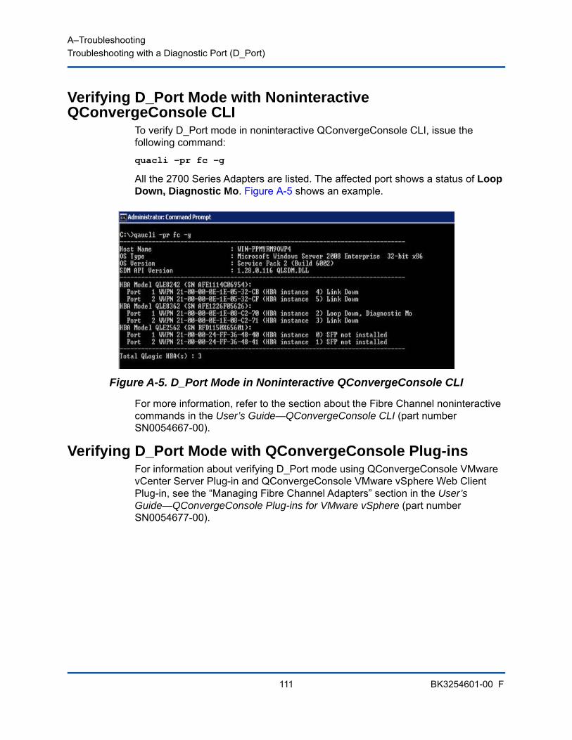
A–TroubleshootingTroubleshooting with a Diagnostic Port (D_Port)
111 BK3254601-00 F
Verifying D_Port Mode with Noninteractive QConvergeConsole CLI
To verify D_Port mode in noninteractive QConvergeConsole CLI, issue the following command:
quacli -pr fc -g
All the 2700 Series Adapters are listed. The affected port shows a status of Loop Down, Diagnostic Mo. Figure A-5 shows an example.
Figure A-5. D_Port Mode in Noninteractive QConvergeConsole CLI
For more information, refer to the section about the Fibre Channel noninteractive commands in the User’s Guide—QConvergeConsole CLI (part number SN0054667-00).
Verifying D_Port Mode with QConvergeConsole Plug-insFor information about verifying D_Port mode using QConvergeConsole VMware vCenter Server Plug-in and QConvergeConsole VMware vSphere Web Client Plug-in, see the “Managing Fibre Channel Adapters” section in the User’s Guide—QConvergeConsole Plug-ins for VMware vSphere (part number SN0054677-00).

112 BK3254601-00 F
B Specifications
This appendix provides specifications for the QLE274x-DEL Adapters.
Physical CharacteristicsTable B-1 lists the physical characteristics for the QLE274x-DEL Adapters.
Power RequirementsTable B-2 lists the power requirements for the QLE274x-DEL Adapters.
Table B-1. Physical Characteristics
Adapter Type Bracket Installed Length Width
QLE2740-DEL Low profile PCIe card Full height 6.6 inches 2.731 inches
QLE2740L-DEL Low profile PCIe card Low profile 6.6 inches 2.731 inches
QLE2742-DEL Low profile PCIe card Full height 6.6 inches 2.731 inches
QLE2742L-DEL Low profile PCIe card Low profile 6.6 inches 2.731 inches
QME2742-DEL Dell PowerEdge mezzanine adapter
— Conforms to the Dell mezzanine card form factor
Table B-2. Power Requirements
Adapter Nominal Power Maximum Power
QLE2740-DEL 8.6W 10.65W
QLE2740L-DEL 8.6W 10.65W
QLE2742-DEL 9.3W 11.5W
QLE2742L-DEL 9.3W 11.5W
QME2742-DEL 7W 8.3W
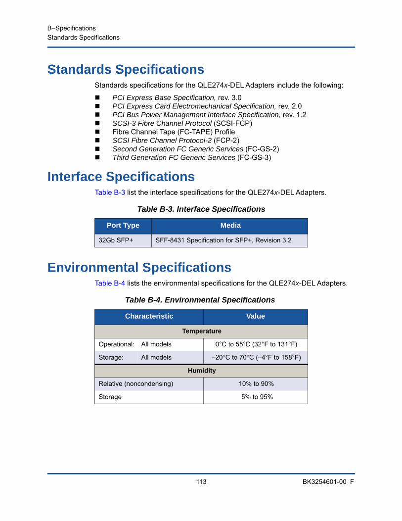
B–SpecificationsStandards Specifications
113 BK3254601-00 F
Standards SpecificationsStandards specifications for the QLE274x-DEL Adapters include the following:
PCI Express Base Specification, rev. 3.0 PCI Express Card Electromechanical Specification, rev. 2.0 PCI Bus Power Management Interface Specification, rev. 1.2 SCSI-3 Fibre Channel Protocol (SCSI-FCP) Fibre Channel Tape (FC-TAPE) Profile SCSI Fibre Channel Protocol-2 (FCP-2) Second Generation FC Generic Services (FC-GS-2) Third Generation FC Generic Services (FC-GS-3)
Interface SpecificationsTable B-3 list the interface specifications for the QLE274x-DEL Adapters.
Environmental SpecificationsTable B-4 lists the environmental specifications for the QLE274x-DEL Adapters.
Table B-3. Interface Specifications
Port Type Media
32Gb SFP+ SFF-8431 Specification for SFP+, Revision 3.2
Table B-4. Environmental Specifications
Characteristic Value
Temperature
Operational: All models 0°C to 55°C (32°F to 131°F)
Storage: All models –20°C to 70°C (–4°F to 158°F)
Humidity
Relative (noncondensing) 10% to 90%
Storage 5% to 95%
114 BK3254601-00 F
C QConvergeConsole GUI
This appendix provides the following information about QConvergeConsole GUI:
Introduction to QConvergeConsole GUI
“Downloading QConvergeConsole Documentation” on page 115
“Downloading and Installing Management Agents” on page 115
“Installing QConvergeConsole GUI” on page 116
“What Is in the QConvergeConsole Help System” on page 119
Introduction to QConvergeConsole GUIQConvergeConsole GUI is a Web-based client and server GUI management tool that provides centralized management and configuration of QLogic adapters within the entire network (LAN and SAN).
On the server side, QConvergeConsole GUI runs as an Apache Tomcat™ application server. After QConvergeConsole GUI is launched on the application server, you can connect to QConvergeConsole GUI through a browser, either locally on the server or remotely from another computer. Your browser window becomes the client used to connect to servers that host the QLogic adapters and connected storage devices within the network.
Use the QConvergeConsole GUI main window to connect to servers that host QLogic adapters. Each host server can include a combination of the following QLogic adapters:
32Gb Fibre Channel Adapters (QLE274x-DEL, QLE274xL-DEL)
32Gb Fibre Channel Mezzanine Card (QME2742-DEL)
NOTE
For information on installing QConvergeConsole GUI, refer to the Installation Guide—QConvergeConsole GUI (part number SN0051105-00). All procedural information for the QConvergeConsole GUI utility is covered in the QConvergeConsole Help.
C–QConvergeConsole GUIDownloading QConvergeConsole Documentation
115 BK3254601-00 F
Note the following:
QConvergeConsole GUI works with the Windows Server 2016, Windows Server 2012, Red Hat Linux® Advanced Server and Enterprise Server, Novell® SUSE® Linux Enterprise Server (SLES®), and Oracle Linux—Unbreakable Enterprise Kernel (UEK). Multiple operating system support allows control of heterogeneous environments.
QConvergeConsole GUI runs on the following Web browsers: Google Chrome™, Mozilla® Firefox®, Microsoft® Internet Explorer®, Opera®, Apple® Safari®. For details on browser versions, see the QConvergeConsole Readme, which you can download at www.cavium.com, Downloads.
Downloading QConvergeConsole DocumentationTo download the Installation Guide—QConvergeConsole GUI (part number SN0051105-00), go to www.cavium.com and click Downloads.
Downloading and Installing Management AgentsTo manage the adapters on a local or remote host, the management agents (also called agents) used by the host’s adapters must already be installed on the host. The agent for Fibre Channel is qlremote.
To connect to a remote host, at least one management agent used by any of the host’s adapters must be installed and running on the host. Only protocols whose agents are installed and running are shown under the host’s system tree node.
Management agents are not automatically installed by the QConvergeConsole GUI installer and must be downloaded and installed separately. You can download the agents from the Cavium® Web site Downloads page, or using the built-in Agent Installer.
NOTE
Some auxiliary help features, such as the Search and Index tools, may not work properly in every Web browser.
C–QConvergeConsole GUIInstalling QConvergeConsole GUI
116 BK3254601-00 F
Installing the Agents from the Cavium Web SiteTo obtain the agents from the Cavium Web site and install them (Windows and Linux, all versions):
1. Go to www.cavium.com and click Downloads:
2. Click the product type tab Adapters, and then select the by Model button.
3. To define a search, click an item in the adapter, model, and OS selection columns, and then click Go.
4. Download the following for each adapter on the host server:
SuperInstaller Readme and Release Notes
5. Install the agents by running the SuperInstaller. For detailed information on running the SuperInstaller, refer to the Readme and Release Notes.
Installing the Agents Using the Built-in Agent InstallerTo access the QCC Agent Installer within QConvergeConsole GUI:
1. Point to the gear icon , point to Help, and then click Download Agent Installers.
The QCC Agent Installer Utility opens in a separate window and lists links for the platform that the utility has detected.
2. For each agent installer to download, click the link.
3. In the File Download dialog box, click Save.
Installing QConvergeConsole GUIRefer to the installation procedure for your operating system.
Installing QConvergeConsole in a Windows Environment
Installing QConvergeConsole in a Linux Environment
Installing QConvergeConsole in Silent Mode
NOTE
For detailed installation instructions, refer to the Installation Guide—QConvergeConsole GUI (part number SN0051105-00).
C–QConvergeConsole GUIInstalling QConvergeConsole GUI
117 BK3254601-00 F
Installing QConvergeConsole in a Windows EnvironmentThe QConvergeConsole Installer for Windows is a self-extracting utility that installs QConvergeConsole and related files.
To install QConvergeConsole in a Windows environment:
1. Locate the directory where you downloaded the installation file, and then double-click the following file:
QConvergeConsole_Installer_Windows_<version>.exe
2. If an Open File security dialog box appears, click Run.
The InstallAnywhere utility prepares to install QConvergeConsole.
3. In the Tomcat Port Number Setup dialog box, enter a valid port number in the range 1025–65536, or accept the default port number, 8080. Then click Next to continue.
4. In the next dialog box, select Yes if you want a localhost-only installation. If you do not want a localhost-only installation, select No.
5. In the Pre-Installation Summary dialog box, verify that the information is correct, and then click Install to proceed.
The installer displays the progress of the installation.
A message box prompts you to confirm if you want to enable the SSL feature, which allows data to be encrypted within a secure layer before passing it to and from the server.
6. To enable the SSL feature, click Yes. Or to disable SSL, click No.
7. In the Install Complete dialog box, click Done to exit the installer.
You have installed QConvergeConsole on your server.
NOTE
Before you begin, read the QConvergeConsole Release Notes and Readme documents for important, up-to-date product information.
NOTE
The localhost-only option installs QConvergeConsole locally so that you must run it locally (remote connection is not possible). To disable the option, you must uninstall QConvergeConsole and then reinstall it, selecting No in this step.

C–QConvergeConsole GUIInstalling QConvergeConsole GUI
118 BK3254601-00 F
Installing QConvergeConsole in a Linux EnvironmentYou have the option of installing QConvergeConsole in a Linux environment using either a GUI or CLI method. To install from the CLI, see “Installing QConvergeConsole in Silent Mode” on page 119.
You can graphically install QConvergeConsole on a Linux host by running a Virtual Network Computing (VNC®) program on a Windows host. The TightVNC Viewer, a VNC program, can remotely control QConvergeConsole installation on a Linux host.
To install QConvergeConsole in a Linux environment:
1. Open the directory containing the installer file, which is one of the following:
QConvergeConsole_Installer_Linux_i386_<version>.bin QConvergeConsole_Installer_Linux_x64_<version>.bin
2. In the terminal window, verify that the installer file has permission to execute by issuing the ls -lt command at the prompt.
3. To install QConvergeConsole, double-click the QConvergeConsole installer .bin file.
A prompt asks if you want to run or view the contents of the .bin file.
4. Click Run in Terminal.
The installer extracts the files and installs QConvergeConsole in the following directory:
/opt/QLogic_Corporation/QConvergeConsole
The InstallAnywhere window prepares to install QConvergeConsole.
5. In the installation Introduction dialog box, click Next.
6. In the Tomcat Port Number Setup dialog box, enter a valid port number in the range 1025–65536, or accept the default port number, 8080. Then click Next to continue.
7. In the next dialog box, select Yes if you want a localhost-only installation. If you do not want a localhost-only installation, select No.
NOTE
The localhost-only option installs QConvergeConsole locally so that you must run it locally (remote connection is not possible). To disable the option, you must uninstall QConvergeConsole and then reinstall it, selecting No in this step.
C–QConvergeConsole GUIWhat Is in the QConvergeConsole Help System
119 BK3254601-00 F
8. In the Pre-Installation Summary dialog box, read the information, and then click Install. During the installation, the installer notifies you of the status.
9. In the Install Complete dialog box, click Done to exit the installer.
You have installed QConvergeConsole on your server.
Installing QConvergeConsole in Silent ModeYou can install QConvergeConsole from a command prompt in silent mode.
To run the installer in silent mode, issue the following command:
<installer_file_name> -i silent -DUSER_INPUT_PORT_NUMBER=<A_NUMBER>
What Is in the QConvergeConsole Help SystemTo access the QConvergeConsole Help system while the GUI utility is running,
point to the gear icon , point to Help, and then click Browse Contents. The help system provides topics containing details of the following:
QConvergeConsole Overview describes the application and lists the supported adapters.
Getting Started shows how to start using QConvergeConsole and the help system. It also describes how to initiate automatic e-mail notifications and set security on adapters installed for a selected host.
Managing Host Connections describes how to connect to a host, create and use a host group, view host information, and disconnect from one or more host servers.
Displaying Host Information describes how to view general host information.
Displaying Adapter Information describes how to view general adapter information.
Displaying Device Information describes how to view information about a device (disk or tape).
Using Reports describes the different types of reports and how to generate, view, and save them using QConvergeConsole's report facility.
Managing Fibre Channel and FCoE Adapters describes how to do the following for a Fibre Channel Adapter (2400/2500/2600 Series) or Converged Network Adapter (8100/8200 Series):
Display and edit adapter-specific information for the selected adapter. View and modify adapter configuration and settings. Update the adapter’s Flash memory or Fibre Channel/FCoE driver.

C–QConvergeConsole GUIWhat Is in the QConvergeConsole Help System
120 BK3254601-00 F
Managing Fibre Channel and FCoE Ports describes how to do the following for a port on a Fibre Channel Adapter or a Converged Network Adapter:
View and modify the parameters and statistics for the selected port. Use the advanced utilities, manage virtual ports, and run diagnostics.
Managing iSCSI Ports shows and describes the parameters on the iSCSI port management pages for the 8200 Series Converged Network Adapters.
Managing Gigabit Ethernet Adapters describes how to view NetXtreme gigabit adapter attributes and configure QLE84xx and FastLinQ Ethernet adapters.
Managing Ethernet (NIC) Ports shows and describes the parameters and configuration options provided on the NIC port management pages for Series Intelligent Ethernet Adapters, as well as 8100/8200 Series Converged Network Adapters.
Using the Wizards describes how to use QConvergeConsole wizards to update the following: Flash, drivers, NIC parameters, Fibre Channel and FCoE parameters, parameters files, passwords, and agents.
Troubleshooting describes tools you can use to resolve the problems that can occur when installing and using the adapter. It also provides the procedures for tracing QConvergeConsole GUI and agent activity, if directed to do so by your authorized service provider.
Technical Support explains how to obtain technical support, gives instructions for downloading software and documentation, and provides contact information.
121 BK3254601-00 F
D Regulatory Information
This appendix provides warranty, regulatory, and compliance information for the Fibre Channel Adapters covered in this guide.
WarrantyFor information about your Dell warranty, see your system documentation.
Regulatory and Compliance InformationLaser Safety, FDA Notice
This product complies with DHHS Rules 21CFR Chapter I, Subchapter J. This product has been designed and manufactured according to IEC60825-1 on the safety label of laser product.
Class 1 Laser Product
Caution—Class 1 laser radiation when openDo not view directly with optical instruments
Appareil laser de classe 1
Attention—Radiation laser de classe 1Ne pas regarder directement avec des instruments optiques
Produkt der Laser Klasse 1
Vorsicht—Laserstrahlung der Klasse 1 bei geöffneter Abdeckung Direktes Ansehen mit optischen Instrumenten vermeiden
Luokan 1 Laserlaite
Varoitus—Luokan 1 lasersäteilyä, kun laite on aukiÄlä katso suoraan laitteeseen käyttämällä optisia instrumenttej
CLASS I LASER

D–Regulatory InformationRegulatory and Compliance Information
122 BK3254601-00 F
Agency CertificationThe following section contains a summary of EMI/EMC test specifications performed on model HD8310405 and CU0310421 to comply with radiated emission, radiated immunity, and product safety standards.
EMI and EMC Requirements
FCC Rules, CFR Title 47, Part 15, Subpart B: Class AFCC compliance information statement: This device complies with Part 15 of the FCC Rules. Operation is subject to the following two conditions: (1) this device may not cause harmful interference, and (2) this device must accept any interference received, including interference that may cause undesired operation.
Industry Canada, ICES-003:2004: Class AThis Class A digital apparatus complies with Canadian ICES-003.Cet appareil numérique de la classe A est conformé à la norme NMB-003 du Canada.
CE Mark 2004/108/EC EMC Directive ComplianceEN55022:2010/CISPR 22:2009+A1:2010: Class A EN55024:2010EN61000-3-2:2006 A1+A2:2009EN61000-3-3:2008
EN61000-4-2: ESDEN61000-4-3: RF Electro Magnetic FieldEN61000-4-4: Fast Transient/BurstEN61000-4-5: Fast Surge Common/DifferentialEN61000-4-6: RF Conducted SusceptibilityEN61000-4-8: Power Frequency Magnetic FieldEN61000-4-11: Voltage Dips and Interrupt
VCCI: 20011-04; Class A
AS/NZS; CISPR 22:2009+A1:2010 Class A

D–Regulatory InformationRegulatory and Compliance Information
123 BK3254601-00 F
Korea CertificationKC-RRA KN22 KN24 (2011) Class A
Product Name/Model—2700 Series Adapter Certification Holder—QLogic CorporationManufactured Date—Refer to date code listed on productManufacturer/Country of Origin—QLogic Corporation/USA
Korean Language Format—Class A
Product Safety Compliance
UL, cUL Product SafetyUL60950-1 (2nd Edition), 2007CSA C22.2 60950-1-07 (2nd Edition) 2007
Use only with listed ITE or equivalent.
Complies with 21 CFR 1040.10 and 1040.11.
Complies with 21 CFR 1040.10 and 1040.11.
For use with UL Listed Servers or equivalent.
Power off the computer and all attached devices such as monitors, printers, and external components before installing the accessory card or equivalent.
2006/95/EC Low Voltage DirectiveTUV EN60950-1:2006+A11+A1+A12 2nd Edition
TUV IEC 60950-1:2005 2nd Edition Am 1:2009 CB
A class equipment(Business purpose info/telecommunications equipment)
As this equipment has undergone EMC registration for business purpose, the seller and/or the buyer is asked to beware of this point and in case a wrongful sale or purchase has been made, it is asked that a change to household use be made.

Corporate Headquarters Cavium, Inc. 2315 N. First Street San Jose, CA 95131 408-943-7100
International Offices UK | Ireland | Germany | France | India | Japan | China | Hong Kong | Singapore | Taiwan | Israel
Copyright © 2016-2018 Cavium, Inc. All rights reserved worldwide. QLogic Corporation is a wholly owned subsidiary of Cavium, Inc. Cavium, the Cavium logo, QLogic, and QConvergeConsole are registered trademarks or trademarks of Cavium, Inc. All other brand and product names are trademarks or registered trademarks of their respective owners. This document is provided for informational purposes only and may contain errors. Cavium reserves the right, without notice, to make changes to this document or in product design or specifications. Cavium disclaims any warranty of any kind, expressed or implied, and does not guarantee that any results or performance described in the document will be achieved by you. All statements regarding Cavium’s future direction and intent are subject to change or withdrawal without notice and represent goals and objectives only.