Fiber-reinforced hydrogel scaffolds for heart valve … reinforced hydrogel .pdf · See...
14
See discussions, stats, and author profiles for this publication at: http://www.researchgate.net/publication/261737082 Fiber-reinforced hydrogel scaffolds for heart valve tissue engineering ARTICLE in JOURNAL OF BIOMATERIALS APPLICATIONS · APRIL 2014 Impact Factor: 2.76 · DOI: 10.1177/0885328214530589 · Source: PubMed CITATIONS 4 DOWNLOADS 95 VIEWS 140 9 AUTHORS, INCLUDING: Nihal Engin Vrana French Institute of Health and Medical Rese… 38 PUBLICATIONS 356 CITATIONS SEE PROFILE Pinar Zorlutuna University of Notre Dame 26 PUBLICATIONS 590 CITATIONS SEE PROFILE Shilpa Sant University of Pittsburgh 29 PUBLICATIONS 824 CITATIONS SEE PROFILE Ali Khademhosseini Harvard Medical School 424 PUBLICATIONS 13,605 CITATIONS SEE PROFILE Available from: Shilpa Sant Retrieved on: 18 August 2015
Transcript of Fiber-reinforced hydrogel scaffolds for heart valve … reinforced hydrogel .pdf · See...
Seediscussions,stats,andauthorprofilesforthispublicationat:http://www.researchgate.net/publication/261737082
Fiber-reinforcedhydrogelscaffoldsforheartvalvetissueengineering
ARTICLEinJOURNALOFBIOMATERIALSAPPLICATIONS·APRIL2014
ImpactFactor:2.76·DOI:10.1177/0885328214530589·Source:PubMed
CITATIONS
4
DOWNLOADS
95
VIEWS
140
9AUTHORS,INCLUDING:
NihalEnginVrana
FrenchInstituteofHealthandMedicalRese…
38PUBLICATIONS356CITATIONS
SEEPROFILE
PinarZorlutuna
UniversityofNotreDame
26PUBLICATIONS590CITATIONS
SEEPROFILE
ShilpaSant
UniversityofPittsburgh
29PUBLICATIONS824CITATIONS
SEEPROFILE
AliKhademhosseini
HarvardMedicalSchool
424PUBLICATIONS13,605CITATIONS
SEEPROFILE
Availablefrom:ShilpaSant
Retrievedon:18August2015
http://jba.sagepub.com/Journal of Biomaterials Applications
http://jba.sagepub.com/content/early/2014/04/14/0885328214530589The online version of this article can be found at:
DOI: 10.1177/0885328214530589
published online 14 April 2014J Biomater ApplKhavari-Nejad, Gholamreza Javadi and Ali Khademhosseini
Maryam Eslami, Nihal Engin Vrana, Pinar Zorlutuna, Shilpa Sant, Sungmi Jung, Nafiseh Masoumi, Ramazan AliFiber-reinforced hydrogel scaffolds for heart valve tissue engineering
Published by:
http://www.sagepublications.com
can be found at:Journal of Biomaterials ApplicationsAdditional services and information for
http://jba.sagepub.com/cgi/alertsEmail Alerts:
http://jba.sagepub.com/subscriptionsSubscriptions:
http://www.sagepub.com/journalsReprints.navReprints:
http://www.sagepub.com/journalsPermissions.navPermissions:
http://jba.sagepub.com/content/early/2014/04/14/0885328214530589.refs.htmlCitations:
What is This?
- Apr 14, 2014OnlineFirst Version of Record >>
at UNIV OF PITTSBURGH on April 22, 2014jba.sagepub.comDownloaded from at UNIV OF PITTSBURGH on April 22, 2014jba.sagepub.comDownloaded from
XML Template (2014) [10.4.2014–9:57am] [1–12]//blrnas3/cenpro/ApplicationFiles/Journals/SAGE/3B2/JBAJ/Vol00000/140018/APPFile/SG-JBAJ140018.3d (JBA) [PREPRINTER stage]
Article
Fiber-reinforced hydrogel scaffoldsfor heart valve tissue engineering
Maryam Eslami*1,2,3, Nihal Engin Vrana1,2, Pinar Zorlutuna1,2,4, Shilpa Sant1,2,5,6,Sungmi Jung7, Nafiseh Masoumi1,2,8, Ramazan Ali Khavari-Nejad3, Gholamreza Javadi3
and Ali Khademhosseini*1,2,5
Abstract
Heart valve-related disorders are among the major causes of death worldwide. Although prosthetic valves are widely
used to treat this pathology, current prosthetic grafts cannot grow with the patient while maintaining normal valve
mechanical and hemodynamic properties. Tissue engineering may provide a possible solution to this issue through using
biodegradable scaffolds and patients’ own cells. Despite their similarity to heart valve tissue, most hydrogel scaffolds are
not mechanically suitable for the dynamic stresses of the heart valve microenvironment. In this study, we integrated
electrospun poly(glycerol sebacate) (PGS)–poly("-caprolactone) (PCL) microfiber scaffolds, which possess enhanced
mechanical properties for heart valve engineering, within a hybrid hydrogel made from methacrylated hyaluronic acid
and methacrylated gelatin. Sheep mitral valvular interstitial cells were encapsulated in the hydrogel and evaluated in
hydrogel-only, PGS–PCL scaffold-only, and composite scaffold conditions. Although the cellular viability and metabolic
activity were similar among all scaffold types, the presence of the hydrogel improved the three-dimensional distribution
of mitral valvular interstitial cells. As seen by similar values in both the Young’s modulus and the ultimate tensile strength
between the PGS–PCL scaffolds and the composites, microfibrous scaffolds preserved their mechanical properties in the
presence of the hydrogels. Compared to electrospun or hydrogel scaffolds alone, this combined system may provide a
more suitable three-dimensional structure for generating scaffolds for heart valve tissue engineering.
Keywords
Heart valve, tissue engineering, hydrogel, composite, mechanical properties, electrospun fiber
Introduction
Heart valve disease is a major ailment worldwide result-ing in �300,000 surgeries annually, a number that isexpected to increase over the next 30 years.1,2
Mechanical valves (MV) and bioprosthetic heartvalves are currently the most common heart valvereplacements.1,3 However, they are associated with anumber of limitations. MV, although they rarely needreplacement, are associated with an increased risk forthrombo-embolic complications and necessitate lifelonganti-coagulation therapy.1,3–6 Bioprosthetic valves havea shorter life span than MV (less than 15 years) due tomechanical failure and extensive calcification.1,3,7–9
However, the most important limitation of both mech-anical and bioprosthetic valves is their inanimatenature, which inherently limits their use in pediatricpatients because they do not grow along withthe patient, necessitating recurring replacements.
Journal of Biomaterials Applications
0(0) 1–12
! The Author(s) 2014
Reprints and permissions:
sagepub.co.uk/journalsPermissions.nav
DOI: 10.1177/0885328214530589
jba.sagepub.com
1Division of Biomedical Engineering, Department of Medicine, Brigham
and Women’s Hospital, Harvard Medical School, Cambridge, MA, USA2Harvard-MIT Division of Health Sciences and Technology, Massachusetts
Institute of Technology, Cambridge, MA, USA3Department of Biology, Islamic Azad University, Science and Research
Branch, Tehran, Iran4Biomedical Engineering Program and Mechanical Engineering
Department, University of Connecticut, Storrs, CT, USA5Wyss Institute for Biologically Inspired Engineering, Harvard University,
Boston, MA, USA6Department of Pharmaceutical Sciences University of Pittsburgh, School
of Pharmacy, Pittsburgh, PA, USA7Department of Electrical Engineering and Computer Science,
Massachusetts Institute of Technology, Cambridge, MA, USA8Department of Bioengineering, Pennsylvania State University, University
Park, PA, USA
Corresponding authors:
Ali Khademhosseini and Maryam Eslami, 65 Landsdowne Street, PRB 252,
Cambridge, MA 02139, USA.
Email: [email protected]; [email protected]
at UNIV OF PITTSBURGH on April 22, 2014jba.sagepub.comDownloaded from
XML Template (2014) [10.4.2014–9:57am] [1–12]//blrnas3/cenpro/ApplicationFiles/Journals/SAGE/3B2/JBAJ/Vol00000/140018/APPFile/SG-JBAJ140018.3d (JBA) [PREPRINTER stage]
Tissue engineering strategies such as tissue-engineeredheart valves can create autologous heart valve con-structs that overcome these limitations by retainingthe ability to grow and remodel over time.1,10–15
All four heart valves have a layered cellular struc-ture, consisting of the valvular endothelial cells, thevalvular interstitial cells (VICs), and valvular extracel-lular matrix (ECM). The ECM, the principal compo-nent of heart valves, consists of three layers: fibrosa,spongiosa, and ventricularis. These layers are com-posed of the fibrous macromolecules collagen, proteo-glycans, and elastin, respectively, which confer theunique physical and mechanical properties of thenative valve.3,7,16 Collagen accounts for �60% dryweight of the valve, elastin for �10%, and proteogly-cans for �20%.16,17 VICs are located throughout alllayers, from deep inside to the surface. ECM structureof heart valves is maintained by VICs. The VICs arenot a homogenous cell population and are composed ofcells from different phenotypes such as quiescent fibro-blasts, activated myofibroblasts, and cells with progeni-tor-like phenotypes.18 This unique three-dimensional(3D) environment can be mimicked by hydrogels,which can be generated via photocrosslinking andphysical crosslinking to create homogenous encapsu-lated cell distributions within the structure. These struc-tures can provide a suitable cellular niche for cellproliferation and differentiation through appropriatephysical and chemical characteristics. Natural poly-mer-based hydrogels can be remodeled by cell-mediatedenzymatic degradation. However, these polymers donot provide sufficient mechanical strength to withstandthe constant stress that mechanically active tissues, suchas heart valves, experience. Natural polymers can bechemically modified to incorporate photocrosslinkablemoieties, such as methacrylates, so that they can form3D hydrogel structures to control cellular activities. Inour previous studies, we have developedphotocrosslinkable natural polymers through acryla-tion chemistry. The modified natural polymers arecheap and cell-friendly material systems that areuseful for biofabrication and can be used for creatinghydrogel-based cell-laden tissue constructs.19–21
Hyaluronic acid (HA) is a natural, non-sulfated gly-cosaminoglycan that plays an important role in heartvalve morphogenesis and wound repair.17,22–24 HA andits derivatives have been widely used as hydrogels fortissue engineering due to its inherent biocompatibilityand biodegradability characteristics, as well as their gel-forming properties.22,25,26 Using HA as a heart valvetissue engineering material could provide key advan-tages because it has been shown to promote elastinsecretion in VICs.24,27,28 Furthermore, HA can be mod-ified to methacrylated hyaluronic acid (HAMA) andthus can be rendered photocrosslinkable upon
ultraviolet (UV) exposure. However, HA alone doesnot promote cell spreading; thus, combining HAMAand methacrylated gelatin (GelMA) could provide amore suitable microenvironment for the cells.17
However, these hydrogels lack the structural integritynecessary for heart valve tissue formation. The mech-anical shortcomings of the hydrogel structure can beaddressed by adding a microfibrous component to rein-force the structure and to provide contact guidance,which is essential for directing the internal organizationof the cells.29–33 We recently engineered microfibrouspoly(glycerol sebacate)–poly("-caprolactone) (PGS–PCL) synthetic scaffolds that could mimic the mechan-ical properties in the human aortic valve.29 Thesefibrous scaffolds can be produced by electrospinning,resulting in a highly porous structure that retains desir-able mechanical properties29,30,34–36 such that it canaccommodate directional tensile loads while maintain-ing mechanical flexibility.6,9,33 However, the high por-osity of the PGS–PCL microfibrous scaffolds allowsseeded cells to migrate out of the structure.Furthermore, cells tend to attach only on the surfaceof the scaffold, which makes producing fully cellular-ized 3D structures difficult.29
The goal of this study was to create a compositebiomaterial that combines the advantageous propertiesof ECM-mimicking hydrogels and elastomeric PGS–PCL electrospun (ES) scaffolds to mimic the cellularenvironment and mechanical properties of nativeheart valve tissue. The hydrogel component of the com-posite scaffold developed in this study retains cellswithin the composite structure, while the PGS–PCLcomponent provides mechanical strength and aporous structure to support tissue growth. A compositeof gelatin and HA provides us with a similar ECMmicroenvironment to that of the VICs in vivo.16,17
However, in a hydrogel configuration, this structurelacks the mechanical properties necessary to withstandthe dynamic environment of the heart valve tissue.Therefore, by inclusion of fibrous scaffold within thehydrogels, a more robust structure can be obtained.We used VICs to test the suitability of the composites’physical and mechanical properties for heart valvetissue engineering by evaluating several physicochem-ical parameters, such as the swelling ratio, stiffness,porosity, and in vitro enzymatic degradation behavior,as well as the initial in vitro analysis.
Materials and methods
Synthesis of methacrylated HA and GelMA
HA sodium salt (Mn: 7.52� 105kDa; Life-coreBiomedical, Chaska, MN) was dissolved to a final con-centration of 1% w/v in deionized water (dI H2O).
2 Journal of Biomaterials Applications 0(0)
at UNIV OF PITTSBURGH on April 22, 2014jba.sagepub.comDownloaded from
XML Template (2014) [10.4.2014–9:57am] [1–12]//blrnas3/cenpro/ApplicationFiles/Journals/SAGE/3B2/JBAJ/Vol00000/140018/APPFile/SG-JBAJ140018.3d (JBA) [PREPRINTER stage]
The pH of the solution was monitored during this pro-cess. Methacrylic anhydride (Sigma-Aldrich, St. Louis,WI) was added dropwise (2ml/200ml) while maintain-ing the pH at 8.0. The solution was put on ice for sev-eral hours and was monitored every 15min forchecking the pH to be maintained at 8. The solutionwas agitated overnight in a cold room (4�C) and wasthen dialyzed for two days in distilled water (dI H2O)with multiple solution changes using 12–14 kDamolecular weight cut-off (MWCO) dialysis tubes. Thesolutions were lyophilized for one week, and the finalproduct was stored at �80�C for future use.
Porcine skin type A gelatin (Bloom index 300;Sigma-Aldrich, Madison, WI) was methacrylated asdescribed previously.19 Briefly, 10% (w/v) gelatin wasmixed in Dulbecco’s phosphate-buffered saline (DPBS;Invitrogen, Grand Island, NY) and incubated at 60�Cuntil completely dissolved. Methacrylic anhydride(0.8ml/g) (8ml) was added dropwise at a rate of0.5ml/min into the gelatin (10 g) solution. The emulsionwas agitated at 60�C for 1 h. Warm 2� DPBS (40�C)was added to the solution to prevent any further reac-tion. The solution was dialyzed for one week in distilledwater using MWCO dialysis tubes (12–14 kDa) withseveral solution changes. The freeze-drying of the solu-tion for one week then resulted in white, porous foamthat was kept at �80�C to be used in the future.
PGS–PCL microfibrous scaffold formation
PGS–PCL microfibrous scaffolds were prepared byusing a standard electrospinning setup. The copperwire was covered with a non-adhesive special tapewith a glass slide on top, which acted as a framework.PGS (MW 12,000; gift from Langer Laboratory,Department of Chemical Engineering, MIT,Cambridge, MA) and PCL (MW70,000–90,000;Sigma-Aldrich, Madison, WI) were dissolved at a 2:1ratio in anhydrous chloroform–ethanol (Sigma-Aldrich, Madison, WI) (9:1 v/v) and were electrospunat 12.5 kV. The total polymer was 33%. Pure PCL scaf-folds were electrospun using 16% w/v polymer solutionbecause it was difficult to electrospin the highly viscous33% w/v PCL solution.29 The fibers were fabricated,while the distance between the needle (21-gaugeneedle) and the collector was kept at 18 cm, at a flowrate of 2ml/h. Each sample was fabricated in 20min;the resulting scaffolds were dried overnight in a vacuumdesiccator and all residual solvents were removed.
Hydrogel preparation
A hydrogel precursor solution (2.5% GelMA macro-mer, 0.5% HAMA macromer) was mixed with endo-thelial basal medium (EBM-2; Lonza,
Walkersville, MD). The solution was crosslinked byadding the photoinitiator (PI) 2-hydroxy-1- (4-(hydro-xyethoxy) phenyl)-2-methyl-1-propanone (Irgacure2959, BASF, Ludwigshafen, Germany) to a final con-centration of 0.1% (v/w) and exposing it to UV light(�¼ 408 nm) for 45 s at 2.6mW/cm2. The resultinghydrogel (20 ml initial solution volume, �6mm diam-eter, �0.5mm thick) was used as a control and wasalso used for making the composite scaffolds.
Fabrication of composite hydrogel/microfibrousPGS–PCL scaffolds
PGS–PCL bulk sheets were used to create 6-mm diam-eter scaffolds. The PGS–PCL scaffolds were put intocontact with the precursor hydrogel solution (20 ml;2.5% GelMA/0.5% HA/0.1% PI). Once the scaffoldfully absorbed the solution, the resulting compositewas crosslinked using UV light (�¼ 408 nm,2.6mW/cm2, 45 s).
Hydrogel precursor solution soaking into PGS–PCLand PCL fibers
Scaffolds (6-mm diameter) were created from bothPGS–PCL and PCL-only (negative control) and werethen filled with 20 ml hydrogel solution (2.5% GelMA/0.5% HAMA/0.1% PI) by putting the solution volumeon top of each scaffold. Soaking of the drop into thePGS–PCL actual fibers was imaged as both sequentialseries (1-s intervals) and in video format. PCL-onlyscaffolds were used as the negative control.
Physical characterization of the scaffold
Mechanical properties. For mechanical characterizationof the samples, a uniaxial elongation test was per-formed on at least six samples using an Instron 544(Instron, Norwood, MA) and a 10 -N load cell.ES meshes were cut into rectangular shapes(5mm� 20mm). In order to prepare composite sam-ples for mechanical testing, PGS–PCL scaffolds werecut and placed in the molds. Molds were filled by pipet-ting 20 ml hydrogel solution (2.5% GelMA/0.5%HAMA/0.1% PI) on top of each ES scaffold.Composites were formed by exposing the mold to theUV light (�¼ 408 nm, 2.6 mW/cm2, 45 s) and thendetached from the mold. The composite samples weretested while still wet. Sandpapers were attached to thetop and bottom of the composite samples to preventthem from slipping before failure. The samples wereloaded at a rate of 7mm/min. The elastic modulus(EM) was measured using the Young’s modulus basedon the linear portion of the stress–strain curve. Theultimate tensile strength (UTS) was calculated using
Eslami et al. 3
at UNIV OF PITTSBURGH on April 22, 2014jba.sagepub.comDownloaded from
XML Template (2014) [10.4.2014–9:57am] [1–12]//blrnas3/cenpro/ApplicationFiles/Journals/SAGE/3B2/JBAJ/Vol00000/140018/APPFile/SG-JBAJ140018.3d (JBA) [PREPRINTER stage]
the maximum strength obtained from the stress–straincurve.
Swelling ratio. Hydrogels and composite scaffolds wereprepared as described above. The swelling behavior ofthe hydrogel and the composite was studied after equi-librating the samples in PBS at 37�C for 24 h. Theexcess liquid was removed from the completely swollensamples before weighing (swollen weight). The sampleswere then freeze-dried and weighed again (dry weight)(n� 6). The swelling ratio was measured by dividing thesamples’ swollen weight by the dry weight. For thecomposites, the dry weight of the PGS–PCL scaffoldwas measured and subtracted during the calculationof swelling ratio.
In vitro hydrogel and the composite scaffold’s enzymatic
degradation. Hydrogel samples (n� 6) were crosslinkedas described above. Collagenase (1 U/ml) fromClostridium histolyticum (Sigma-Aldrich, Saint Louis,MO) and hyaluronidase type 1-S (100 U/ml) frombovine testes (Sigma-Aldrich, Saint Louis, MO) solu-tions were prepared in PBS from stock solutions.Samples were incubated in collagenase (1U/mg;n� 6), hyaluronidase (100 U/ml; n� 6), or PBS (n¼ 6)at 37�C for 24 h. The samples were weighed before andafter adding the enzymatic solution. After incubation,the samples were washed, lyophilized, and weighedagain. The degradation was calculated by determiningthe decrease in mass. The samples were stored at 37�Cfor 48 h before fixing them in 2.5% glutaraldehyde andobserving the hydrolytic degradation via scanning elec-tron microscopy (SEM).
Scanning electron microscopy
Scanning electron microscopy (SEM) images weretaken with the use of a field emission scanning electronmicroscope (FE-SEM; JSM 6700, JEOL, Peabody,MA) to characterize the pore size of the scaffold andthe fiber morphology. Images were taken from bothsurface and internal cross-sections of the hydrogel-only, the composite scaffold, and the PGS–PCL-onlyscaffold with and without cells (day 0, day 21). Thesamples were fixed in 2.5% glutaraldehyde and werefrozen using liquid nitrogen. Then they were stored at�80�C. The samples were lyophilized before sputtercoating them with an iron coater using palladium andplatinum. The SEM was equilibrated at 40 mA for 40 sprior to taking the images.
Mitral valvular interstitial cells
Cell culture. Mitral valvular interstitial cells (MVICs;gift from Dr Bischoff, Children’s Hospital, Boston,
MA) having passage numbers between 3 and 4 weremaintained in EBM-2 (Lonza)supplemented with 10%fetal bovine serum (Sigma-Aldrich, Saint Louis, MO)and 1% penicillin–streptomycin (Gibco, Langley, OK)at 37�C and 5% CO2. Cells were cultured on gelatin-coated flasks and were passaged weekly with mediachanged every other day.
Encapsulation of MVICs within hydrogels (GelMA/HAMA)
and composite scaffolds. MVICs were trypsinizedand re-suspended in the hydrogel precursor solu-tion (2.5% GelMA/0.5% HAMA) containing 0.1%(w/v) PI at a concentration of 6� 106 cells/ml. Thehydrogel and composite scaffolds were fabricatedas previously described. The scaffolds and hydrogelprecursor solution with cells were exposed to2.6mW/cm2 UV light (408 nm) for 45 s and werethen incubated in medium (EBM2) under standardculture conditions for 21 days. The medium waschanged every 30min for the first 2 h to remove theremaining PI. The medium was then changed everyother day.
Seeding MVICs on PGS–PCL scaffolds. PGS–PCL scaffoldswere sterilized prior to seeding the cells by immersingthem in 70% ethanol for 2 h. It was followed by UVexposure and washing with DPBS. Then, the cells wereseeded onto scaffolds (0.6 cm� 0.6 cm) at a concentra-tion of 2� 104 cells/scaffold. Cells were seeded ontoscaffolds by adding 20 ml of cell suspension to scaffoldsin 48-well plates and incubating them for 1 h to allowthe cells to attach. The medium was changed everyother day.
Cell viability, attachment, spreading, proliferation, and
metabolism
Cell viability. The cell viability within the scaf-folds was quantified with the use of a Live/Deadassay (Calcein-AM/Ethidiumhomodimer; Invitrogen,Carlsbad, CA) per manufacturer’s protocol. The viabil-ity of the cells was determined on days 1 (24 h after cellseeding/encapsulation) and 21 of culture for each typeof sample. The samples were imaged using a NikonFluorescent microscope. Image J software was used toassess the percent viability.
Cell attachment and cell spreading. Cell adhesion stu-dies were performed by encapsulating 6� 106 cells/mlMVICs with each scaffold mentioned above and incu-bating them for 21 days. Media of the samples werechanged every other day. After 21 days, the scaffoldswere fixed and stained by rhodamine-phalloidin(Invitrogen, Grand Island, NY) and 4, 6-diamidino-2-phenylindole (DAPI; Invitrogen, Grand
4 Journal of Biomaterials Applications 0(0)
at UNIV OF PITTSBURGH on April 22, 2014jba.sagepub.comDownloaded from
XML Template (2014) [10.4.2014–9:57am] [1–12]//blrnas3/cenpro/ApplicationFiles/Journals/SAGE/3B2/JBAJ/Vol00000/140018/APPFile/SG-JBAJ140018.3d (JBA) [PREPRINTER stage]
Island, NY).The degree of cell attachment and spread-ing was assessed by FE-SEM.
Cell metabolism. The metabolic activity of cells oneach scaffold or hydrogel at days 1 and 21 of culturewas assessed with the use of the Alamar Blue (AB)assay according to manufacturer’s protocol(Invitrogen, Carlsbad, CA). Cells were seeded ontoscaffolds or were encapsulated within plain hydrogelsor composite scaffolds (n¼ 3/group). The cell-seededscaffolds were then transferred to new wells to avoidcounting cells that had adhered to the plate surfaceduring seeding. One well, which contains onlymedium, was used to measure background signal,while two cell-free scaffolds/hydrogels were used asthe negative controls. The control scaffolds had thesame no-cell condition for each type, as the baselinereadings were not the same and this was taken intoaccount in calculations. AB was dissolved in 10% v/vmedium and then added to each well. The samples werekept in an incubator in AB for 2 h at 37�C.Subsequently, solution from each well was transferredto wells in a 96-well plate (100ml, n¼ 3/group), and thefluorescence was measured (excitation: 540 nm, emis-sion: 590 nm). The 21-day measurements were normal-ized to the corresponding measurements from day 1.
Statistical analysis
Statistical analysis was performed using SPSS version15.0 (SPSS Inc., Chicago, IL). Data are shown as the
mean� standard deviation (SD). Kolmogorov–Smirnov test was performed to determine if the factorsare normally distributed. Three groups of PGS–PCLfiber, hydrogel, and composite were compared byone-way analysis of variance. This was then followedby Tukey HSD test. Independent T-test was performedfor comparison of mean of composite, hydrogel, andPGS–PCL groups. A p value �0.05 was consideredstatistically significant. Data are shown as themean�SD.
Results and discussion
Physical characterization of the composite scaffolds
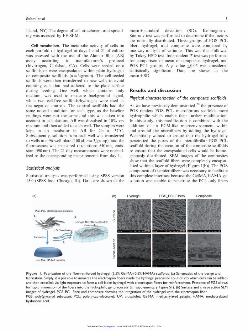
As we have previously demonstrated,29 the presence ofPGS renders PGS–PCL microfibrous scaffolds morehydrophilic which enable their further modification.In this study, this modification is combined with theaddition of an ECM-like microenvironment withinand around the microfibers by adding the hydrogel.We initially wanted to ensure that the hydrogel fullypenetrated the pores of the microfibrillar PGS–PCLscaffold during the creation of the composite scaffoldsto ensure that the encapsulated cells would be homo-genously distributed. SEM images of the compositesshow that the scaffold fibers were completely encapsu-lated within a layer of hydrogel (Figure 1(b)). The PGScomponent of the microfibers was necessary to facilitatethis complete interface because the GelMA/HAMA gelsolution was unable to penetrate the PCL-only fibers
PGS-PCL electrospun microfibers
Immersion
UV Crosslinking
Gel-MA / HA-MA Solution
Hydrogel/ Microfibrous ScaffoldComposites
Sur
face
Hydrogel PGS_PCL Fibers Composite
Cro
ss-s
ectio
n
(b)(a)
Figure 1. Fabrication of the fiber-reinforced hydrogel (2.5% GelMAþ0.5% HAMA) scaffolds. (a) Schematics of the design and
fabrication. Simply, it is possible to immerse the electrospun fibers inside the hydrogel precursor solution (to which cells can be added)
and then crosslink via light exposure to form a cell-laden hydrogel with electrospun fibers for reinforcement. Presence of PGS allows
for rapid immersion of the fibers into the hydrophilic gel precursor (cf. supplementary Figure S1). (b) Surface and cross-section SEM
images of hydrogel, PGS–PCL fiber, and composite showing the integration of the hydrogel with the electrospun fiber.
PGS: poly(glycerol sebacate); PCL: poly("-caprolactone); UV: ultraviolet; GelMA: methacrylated gelatin; HAMA: methacrylated
hyaluronic acid.
Eslami et al. 5
at UNIV OF PITTSBURGH on April 22, 2014jba.sagepub.comDownloaded from
XML Template (2014) [10.4.2014–9:57am] [1–12]//blrnas3/cenpro/ApplicationFiles/Journals/SAGE/3B2/JBAJ/Vol00000/140018/APPFile/SG-JBAJ140018.3d (JBA) [PREPRINTER stage]
(see supplementary Figure S1). Additionally, the gelsolution was absorbed more quickly when the scaffoldwas immersed in the gel solution compared to directlyadding it to the scaffold structure. Thus, the compositestructures were synthesized using this immersion tech-nique. Previously, fiber/hydrogel composite constructswere prepared by simultaneous electrospinning of themicrofibers and electrospraying of the hydrogel becauseof the utilization of hydrophobic polymers.37 Theadvantage of the currently presented method is due tothe ability of the PGS–PCL microfibers to imbibehydrogel precursor solution, the composite can be pro-duced after electrospinning, and cells can be directlyencapsulated within the composite during hydrogelcrosslinking step.
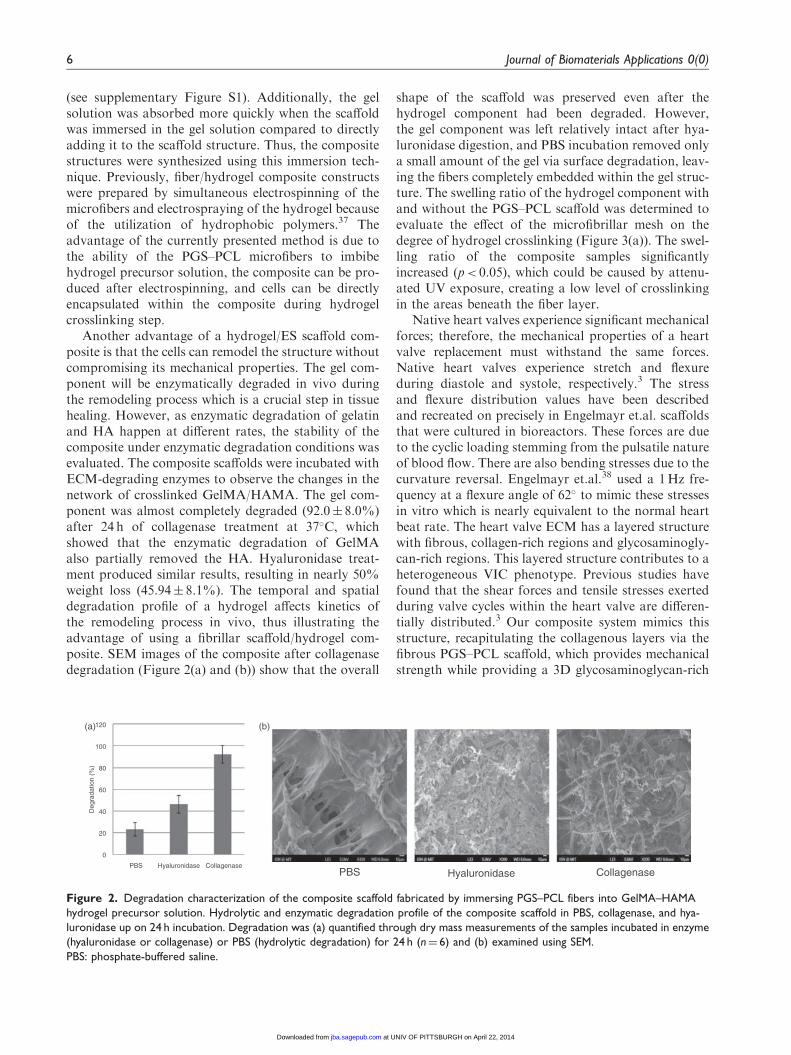
Another advantage of a hydrogel/ES scaffold com-posite is that the cells can remodel the structure withoutcompromising its mechanical properties. The gel com-ponent will be enzymatically degraded in vivo duringthe remodeling process which is a crucial step in tissuehealing. However, as enzymatic degradation of gelatinand HA happen at different rates, the stability of thecomposite under enzymatic degradation conditions wasevaluated. The composite scaffolds were incubated withECM-degrading enzymes to observe the changes in thenetwork of crosslinked GelMA/HAMA. The gel com-ponent was almost completely degraded (92.0� 8.0%)after 24 h of collagenase treatment at 37�C, whichshowed that the enzymatic degradation of GelMAalso partially removed the HA. Hyaluronidase treat-ment produced similar results, resulting in nearly 50%weight loss (45.94� 8.1%). The temporal and spatialdegradation profile of a hydrogel affects kinetics ofthe remodeling process in vivo, thus illustrating theadvantage of using a fibrillar scaffold/hydrogel com-posite. SEM images of the composite after collagenasedegradation (Figure 2(a) and (b)) show that the overall
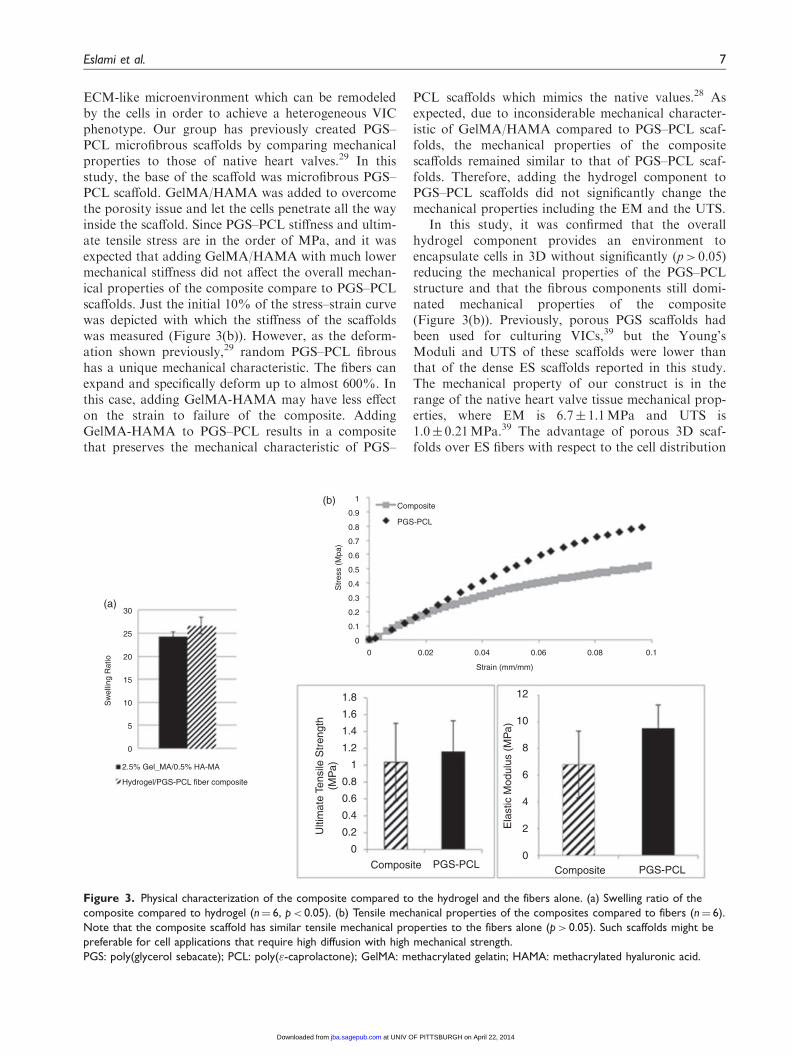
shape of the scaffold was preserved even after thehydrogel component had been degraded. However,the gel component was left relatively intact after hya-luronidase digestion, and PBS incubation removed onlya small amount of the gel via surface degradation, leav-ing the fibers completely embedded within the gel struc-ture. The swelling ratio of the hydrogel component withand without the PGS–PCL scaffold was determined toevaluate the effect of the microfibrillar mesh on thedegree of hydrogel crosslinking (Figure 3(a)). The swel-ling ratio of the composite samples significantlyincreased (p< 0.05), which could be caused by attenu-ated UV exposure, creating a low level of crosslinkingin the areas beneath the fiber layer.
Native heart valves experience significant mechanicalforces; therefore, the mechanical properties of a heartvalve replacement must withstand the same forces.Native heart valves experience stretch and flexureduring diastole and systole, respectively.3 The stressand flexure distribution values have been describedand recreated on precisely in Engelmayr et.al. scaffoldsthat were cultured in bioreactors. These forces are dueto the cyclic loading stemming from the pulsatile natureof blood flow. There are also bending stresses due to thecurvature reversal. Engelmayr et.al.38 used a 1Hz fre-quency at a flexure angle of 62� to mimic these stressesin vitro which is nearly equivalent to the normal heartbeat rate. The heart valve ECM has a layered structurewith fibrous, collagen-rich regions and glycosaminogly-can-rich regions. This layered structure contributes to aheterogeneous VIC phenotype. Previous studies havefound that the shear forces and tensile stresses exertedduring valve cycles within the heart valve are differen-tially distributed.3 Our composite system mimics thisstructure, recapitulating the collagenous layers via thefibrous PGS–PCL scaffold, which provides mechanicalstrength while providing a 3D glycosaminoglycan-rich
PBS Hyaluronidase CollagenasePBS Hyaluronidase Collagenase
Deg
rada
tion
(%)
0
20
40
60
80
100
120(a) (b)
Figure 2. Degradation characterization of the composite scaffold fabricated by immersing PGS–PCL fibers into GelMA–HAMA
hydrogel precursor solution. Hydrolytic and enzymatic degradation profile of the composite scaffold in PBS, collagenase, and hya-
luronidase up on 24 h incubation. Degradation was (a) quantified through dry mass measurements of the samples incubated in enzyme
(hyaluronidase or collagenase) or PBS (hydrolytic degradation) for 24 h (n¼ 6) and (b) examined using SEM.
PBS: phosphate-buffered saline.
6 Journal of Biomaterials Applications 0(0)
at UNIV OF PITTSBURGH on April 22, 2014jba.sagepub.comDownloaded from
XML Template (2014) [10.4.2014–9:57am] [1–12]//blrnas3/cenpro/ApplicationFiles/Journals/SAGE/3B2/JBAJ/Vol00000/140018/APPFile/SG-JBAJ140018.3d (JBA) [PREPRINTER stage]
ECM-like microenvironment which can be remodeledby the cells in order to achieve a heterogeneous VICphenotype. Our group has previously created PGS–PCL microfibrous scaffolds by comparing mechanicalproperties to those of native heart valves.29 In thisstudy, the base of the scaffold was microfibrous PGS–PCL scaffold. GelMA/HAMA was added to overcomethe porosity issue and let the cells penetrate all the wayinside the scaffold. Since PGS–PCL stiffness and ultim-ate tensile stress are in the order of MPa, and it wasexpected that adding GelMA/HAMA with much lowermechanical stiffness did not affect the overall mechan-ical properties of the composite compare to PGS–PCLscaffolds. Just the initial 10% of the stress–strain curvewas depicted with which the stiffness of the scaffoldswas measured (Figure 3(b)). However, as the deform-ation shown previously,29 random PGS–PCL fibroushas a unique mechanical characteristic. The fibers canexpand and specifically deform up to almost 600%. Inthis case, adding GelMA-HAMA may have less effecton the strain to failure of the composite. AddingGelMA-HAMA to PGS–PCL results in a compositethat preserves the mechanical characteristic of PGS–
PCL scaffolds which mimics the native values.28 Asexpected, due to inconsiderable mechanical character-istic of GelMA/HAMA compared to PGS–PCL scaf-folds, the mechanical properties of the compositescaffolds remained similar to that of PGS–PCL scaf-folds. Therefore, adding the hydrogel component toPGS–PCL scaffolds did not significantly change themechanical properties including the EM and the UTS.
In this study, it was confirmed that the overallhydrogel component provides an environment toencapsulate cells in 3D without significantly (p> 0.05)reducing the mechanical properties of the PGS–PCLstructure and that the fibrous components still domi-nated mechanical properties of the composite(Figure 3(b)). Previously, porous PGS scaffolds hadbeen used for culturing VICs,39 but the Young’sModuli and UTS of these scaffolds were lower thanthat of the dense ES scaffolds reported in this study.The mechanical property of our construct is in therange of the native heart valve tissue mechanical prop-erties, where EM is 6.7� 1.1MPa and UTS is1.0� 0.21MPa.39 The advantage of porous 3D scaf-folds over ES fibers with respect to the cell distribution
Sw
ellin
g R
atio
2.5% Gel_MA/0.5% HA-MA
Hydrogel/PGS-PCL fiber composite
30
25
20
15
10
5
0
Composite
PGS-PCL
Composite PGS-PCL Composite PGS-PCL
Str
ess
(Mpa
)
1
0.9
0.8
0.7
0.6
0.5
0.4
0.3
0.2
0.1
0
0 0.02 0.04 0.06 0.08 0.1
Strain (mm/mm)
1.8
1.6
1.4
1.2
1
0.8
0.6
0.4
0.2
0
Ulti
mat
e Te
nsile
Str
engt
h(M
Pa)
Ela
stic
Mod
ulus
(M
Pa)
12
10
8
6
4
2
0
(a)
(b)
Figure 3. Physical characterization of the composite compared to the hydrogel and the fibers alone. (a) Swelling ratio of the
composite compared to hydrogel (n¼ 6, p< 0.05). (b) Tensile mechanical properties of the composites compared to fibers (n¼ 6).
Note that the composite scaffold has similar tensile mechanical properties to the fibers alone (p> 0.05). Such scaffolds might be
preferable for cell applications that require high diffusion with high mechanical strength.
PGS: poly(glycerol sebacate); PCL: poly("-caprolactone); GelMA: methacrylated gelatin; HAMA: methacrylated hyaluronic acid.
Eslami et al. 7
at UNIV OF PITTSBURGH on April 22, 2014jba.sagepub.comDownloaded from
XML Template (2014) [10.4.2014–9:57am] [1–12]//blrnas3/cenpro/ApplicationFiles/Journals/SAGE/3B2/JBAJ/Vol00000/140018/APPFile/SG-JBAJ140018.3d (JBA) [PREPRINTER stage]
is overcome in the hydrogel/ES composites by theencapsulation of the cells in the hydrogels.
MVIC encapsulation
From cell encapsulation point of view, adding a gel-based cell carrier to a microfibrous scaffold provides ahigher scaffold volume without compromising themechanical properties, which ensures that the cells aredistributed within the entire volume of the scaffoldrather than limiting the cells’ adhesion to the surfaceof the fibers, as it happens with bare fibrous structures.The hydrogel also provides a cellular niche that is moreeasily remodeled because it is enzymatically degradableand contains natural polymers present in the nativeheart valve. Environmental cues from events such asECM damage change the phenotype of VICs withinnative heart valve tissue. A degradable hydrogel struc-ture may help with the stimulation of the VICs tosecrete ECM. Previous research has shown thatadding glycosaminoglycans can increase VICs’ ECMproduction (collagen types I and III) within collagengels.40 However, the researchers incorporated uncros-slinked chondroitin sulfate, a glycosaminoglycan,which eluted quickly from the structure. Thus, oursystem is advantageous because it incorporates a cross-linked glycosaminoglycan component which formscrosslinks with the other ECM-like component, gelatin,thus it cannot be leached out during long cell cultureperiods.
HA is known to stimulate elastin production.41
Furthermore, the presence of HA prevents calcifiednodule formation by VICs in vitro.42 GelMA/HA com-posites have been proven beneficial in other systems,such as HA hydrogels with encapsulated gelatin-conju-gated particles. These HA-based structures were able todirect the osteogenic differentiation of mesenchymalstem cells, while HA gels alone induced cells to formunconnected spheroids.43 A low level of HA was chosenfor two reasons: (i) to obtain more robust structuresand (ii) to prevent it from adversely affecting VICphenotype. High levels of glycosaminoglycans wereobserved in the mitral valves of patients with congestiveheart disease.44 HA comprises 60% of glycosaminogly-can content of heart valves, and it has been implicatedin myxomateous hearts, there is an increase in HA con-tent of heart valves with aging process.42 Suggestingthat a high content of glycosaminoglycans mightadversely affect VIC phenotype rather than facilitatingECM production.
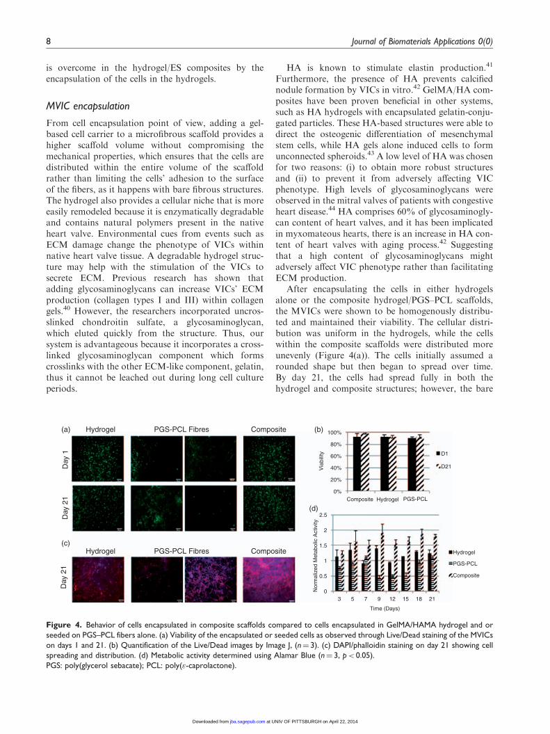
After encapsulating the cells in either hydrogelsalone or the composite hydrogel/PGS–PCL scaffolds,the MVICs were shown to be homogenously distribu-ted and maintained their viability. The cellular distri-bution was uniform in the hydrogels, while the cellswithin the composite scaffolds were distributed moreunevenly (Figure 4(a)). The cells initially assumed arounded shape but then began to spread over time.By day 21, the cells had spread fully in both thehydrogel and composite structures; however, the bare
Composite Hydrogel PGS-PCL
CompositeHydrogel PGS-PCL Fibres
CompositeHydrogel PGS-PCL Fibres
Composite
Hydrogel
PGS-PCL
D1
D21Via
bilit
y
100%
80%
60%
40%
20%
0%
3 5 7 9 12 15 18 21
Time (Days)
Nor
mal
ized
Met
abol
ic A
ctiv
ity
2.5
2
1.5
1
0.5
0
Day
21
Day
21
Day
1
(a)
(c)
(b)
(d)
Figure 4. Behavior of cells encapsulated in composite scaffolds compared to cells encapsulated in GelMA/HAMA hydrogel and or
seeded on PGS–PCL fibers alone. (a) Viability of the encapsulated or seeded cells as observed through Live/Dead staining of the MVICs
on days 1 and 21. (b) Quantification of the Live/Dead images by Image J, (n¼ 3). (c) DAPI/phalloidin staining on day 21 showing cell
spreading and distribution. (d) Metabolic activity determined using Alamar Blue (n¼ 3, p< 0.05).
PGS: poly(glycerol sebacate); PCL: poly("-caprolactone).
8 Journal of Biomaterials Applications 0(0)
at UNIV OF PITTSBURGH on April 22, 2014jba.sagepub.comDownloaded from
XML Template (2014) [10.4.2014–9:58am] [1–12]//blrnas3/cenpro/ApplicationFiles/Journals/SAGE/3B2/JBAJ/Vol00000/140018/APPFile/SG-JBAJ140018.3d (JBA) [PREPRINTER stage]
PGS–PCL scaffold had cells spreading predominantlyon its surface because the dense structure of the ESfibers temporarily limits cellular infiltration. Previousresearch using matrix metalloproteinase-degradablepoly(ethylene glycol) gels showed that a high densityof crosslinking can impede the encapsulated VICs’spreading for up to 14 days37; thus, a low concentrationhydrogel better facilitates cellular remodeling. After 21days of culture, the composite scaffolds showed signifi-cantly more cells around the fibrillar component(Figure 4(b)), which may be caused by cellular migra-tion toward stiffer substrates. The initial encapsulationprocess maintained a high level of cell viability (�90%).At day 21, the viability of MVICs was still above 90%for all three scaffolds (Figure 4(c)), accompanied by a
significant increase in the cell number. The metabolicactivity of seeded cells was used as an indirect methodfor determining cell number. The cells within the com-posite scaffolds showed higher metabolic activity com-pared to those on the scaffold only or within thehydrogel samples at all time points (Figure 4(d)).The metabolic activity showed distinct peaks at varioustime points for the samples, which could be caused bythe cells attaining a quiescent state when a certain cel-lular density was reached.
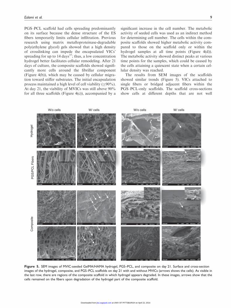
The results from SEM images of the scaffoldsshowed similar trends (Figure 5). VICs attached tosingle fibers or bridged adjacent fibers within thePGS–PCL-only scaffolds. The scaffold cross-sectionsshow cells at different depths that are not well
W/o cells W/o cells W/ cellsW/ cells
Com
posi
teP
GS
/PC
L F
iber
sH
ydro
gel
Figure 5. SEM images of MVIC-seeded GelMA/HAMA hydrogel, PGS–PCL, and composite on day 21. Surface and cross-section
images of the hydrogel, composite, and PGS–PCL scaffolds on day 21 with and without MVICs (arrows shows the cells). As visible in
the last row, there are regions of the composite scaffold in which hydrogel appears degraded. In these images, arrows show that the
cells remained on the fibers upon degradation of the hydrogel part of the composite scaffold.
Eslami et al. 9
at UNIV OF PITTSBURGH on April 22, 2014jba.sagepub.comDownloaded from
XML Template (2014) [10.4.2014–9:58am] [1–12]//blrnas3/cenpro/ApplicationFiles/Journals/SAGE/3B2/JBAJ/Vol00000/140018/APPFile/SG-JBAJ140018.3d (JBA) [PREPRINTER stage]
distributed throughout the scaffold (Figure 5).However, the VICs within the composite structureswere observed at different depths and in greater num-bers on the fibrous component due to the migration ofcells within the hydrogel component.
Previous research showed similar results for micro-fibrillar polyurethane/ECM-based hydrogel compositesthat were implanted in vivo as abdominal wall replace-ments. In this case, the bare ES scaffold samplesshowed limited cell infiltration, whereas the hydrogel/polyurethane (PU) composites showed cells infiltratingthe full thickness of the scaffold by week 4. The mech-anical properties of these structures were also deter-mined by the fibrillar component, where a higheramount of ES fibers created higher tensile strengthand suture strength.45 Using highly crosslinked hydro-gels, such as fibrin gels, together with a photocrosslink-able component can also cause changes in the overallmechanical properties of the composite.46 However, theamount of time necessary to achieve such properties isnot compatible with cellular encapsulation.Additionally, using fiber/hydrogel composites alsoallows fibers to be linked to each other by secondarycrosslinking of the hydrogel component. Thus, theorientation of fiber bundles can be controlled at themicron-scale level to provide the necessary structuralanisotropy. Moreover, the presence of a fibrillar com-ponent in a hydrogel system has been shown in previ-ous research to result in more uniform drug release47 bysignificantly decreasing the initial burst release andincreasing the overall release period, which extendsthe delivery lifetime of growth factors, such as basicfibroblast growth factor, to encapsulated cells and pro-vides more control over cellular phenotype. Nervegrowth factor released in this manner from ES fibersimproved PC12 cell spreading,48 and a similar releasemethod could be used to induce ECM secretion byVICs.
We have recently demonstrated that the presence ofPGS in PGS–PCL scaffolds promotes ECM secretion,49
and also in future studies, we aim to demonstrate that a3D control over ECM secretion by VICs can beattained by their encapsulation in the compositescaffolds.
Conclusions
The composite scaffold described in this studyaddresses some of the limitations of current materialsfor heart valve tissue engineering. The hydrogel com-ponent provides an ECM-mimicking environment andefficient means of VICs’ delivery to the scaffold, whilethe fibrous PGS–PCL mesh allows the cells to spreadand distribute themselves within the hydrogel by pro-viding appropriate mechanical properties to the
otherwise weak hydrogel scaffolds. Furthermore,adding the hydrogel component did not adverselyaffect the scaffold’s mechanical properties based onthe similar values of both Young’s modulus and theUTS of the bare PGS–PCL scaffolds and the compos-ites. The mechanical and biological advantages of thiscomposite scaffold can motivate further studies usingthis technology for potential applications in heart valvetissue engineering.
Acknowledgments
The authors would like to thank Dr Bischoff for providing theSheep mitral valve interstitial cells (MVICs). The authors also
acknowledge Dr Su Ryon Shin, Dr Jesper Hjortnaes,Dr Mahshid Kharaziha, Dr Mohammad Ali Shokrgozar,Dr Naser Aghdami, and Arash Nasajpour for the scientific
viewpoints.
Funding
This study has been supported by the following grants fromthe National Institute of Health (EB007249, DE019024 andHL092836).
Conflict of interest
None declared.
References
1. Sewell-Loftin MK, Chun YW, Khademhosseini A, et al.EMT-inducing biomaterials for heart valve engineering:taking cues from developmental biology. J Cardiovasc
Transl Res 2011; 4: 658–671.2. Yacoub MH and Takkenberg JJ. Will heart valve tissue
engineering change the world? Nat Clin Pract Cardiovasc
Med 2005; 2: 60–61.3. Sacks MS, Schoen FJ and Mayer JE. Bioengineering chal-
lenges for heart valve tissue engineering. Annu Rev Biomed
Eng 2009; 11: 289–313.4. Cannegieter SC, Rosendaal FR and Briet E.
Thromboembolic and bleeding complications in patients
with mechanical heart valve prostheses. Circulation 1994;89: 635–641.
5. Hammermeister KE, Sethi GK, Henderson WG, et al. Acomparison of outcomes in men 11 years after heart-valve
replacement with a mechanical valve or bioprosthesis.Veterans Affairs Cooperative Study on Valvular HeartDisease. N Engl J Med 1993; 328: 1289–1296.
6. Fowler VG and Durack DT. Infective endocarditis.Curr Opin Cardiol 1994; 9: 389–400.
7. Filova E, Straka F, Mirejovsky T, et al. Tissue-engineered
heart valves. Physiol Res 2009; 58(Suppl 2): S141–S158.8. Neuenschwander S and Hoerstrup SP. Heart valve tissue
engineering. Transplant Immunol 2004; 12: 359–365.9. Schoen FJ and Levy RJ. Calcification of bioprosthetic
heart valves. In: Bodnar E, Frater RWM (eds)Replacement cardiac valves. New York: Pergamon, 1991,pp.125–148.
10 Journal of Biomaterials Applications 0(0)
at UNIV OF PITTSBURGH on April 22, 2014jba.sagepub.comDownloaded from
XML Template (2014) [10.4.2014–9:58am] [1–12]//blrnas3/cenpro/ApplicationFiles/Journals/SAGE/3B2/JBAJ/Vol00000/140018/APPFile/SG-JBAJ140018.3d (JBA) [PREPRINTER stage]
10. Schoen FJ and Levy RJ. Founder’s Award, 25th AnnualMeeting of the Society for Biomaterials, perspectives.Providence, RI, April 28–May 2, 1999. Tissue heart
valves: current challenges and future research perspec-tives. J Biomed Mater Res 1999; 47: 439–465.
11. Vesely I. Heart valve tissue engineering. Circ Res 2005;97: 743–755.
12. Hoerstrup SP, Sodian R, Daebritz S, et al. Functionalliving trileaflet heart valves grown in vitro. Circulation2000; 102(19 Suppl 3): III44–III49.
13. Mayer JE Jr. Uses of homograft conduits for right ven-tricle to pulmonary artery connections in the neonatalperiod. Semin Thorac Cardiovasc Surg 1995; 7: 130–132.
14. Kirklin JK, Smith D, Novick W, et al. Long-term func-tion of cyropreserved aortic homografts. A ten-yearstudy. J Thorac Cardiovasc Surg 1993; 106: 154–166.
15. Mol A, Rutten MCM, Driessen NJB, et al. Autologoushuman tissue-engineered heart valves: prospects for sys-temic application. Circulation 2006; 114(1 Suppl):I152–I158.
16. Kunzelman KS, Cochran RP, Murphree SS, et al.Differential collagen distribution in the mitral valve andits influence on biomechanical behavior. J Heart Valve
Dis 1993; 2: 236–244.17. Cloyd KL, El-Hamamsy I, Boonrungsiman S, et al.
Characterization of porcine aortic valvular interstitial
cell ‘calcified’ nodules. PLoS One 2012; 7: e48154.18. Nichol JW, Koshy ST, Bae H, et al. Cell-laden microen-
gineered gelatin methacrylate hydrogels. Biomaterials2010; 31: 5536–5544.
19. Peppas NA, Hilt JZ, Khademhosseini A, et al. Hydrogelsin biology and medicine: from molecular principles tobiotechnology. Adv Mater 2006; 18: 1345–1360.
20. Huston CB, Nichol JW, Aubin H, et al. Synthesis andcharacterization of tunable poly(ethylene glycol): gelatinmethacrylate composite hydrogels. Tissue Eng Part A
2011; 17: 1713–1723.21. Flanagan TC and Pandit A. Living artificial heart valve
alternatives: a review. Eur Cell Mater 2003; 6: 28–45.
22. Tan H, Rubin JP and Marra KG. Injectable in situ form-ing biodegradable chitosan-hyaluronic acid based hydro-gels for adipose tissue regeneration. Organogenesis 2010;6: 173–180.
23. Iocono JA, Krummel TM, Keefer KA, et al. Repeatedadditions of hyaluronan alters granulation tissue depos-ition in sponge implants in mice. Wound Repair Regen
1998; 6: 442–448.24. Shah DN, Recktenwall-Work SM and Anseth KS. The
effect of bioactive hydrogels on the secretion of extracel-
lular matrix molecules by valvular interstitial cells.Biomaterials 2008; 29: 2060–2072.
25. Fraser JR, Laurent TC and Laurent UB. Hyaluronan: itsnature, distribution, functions and turnover. J Intern Med
1997; 242: 27–33.26. Dowthwaite GP, Edwards JC and Pitsillides AA. An
essential role for the interaction between hyaluronan
and hyaluronan binding proteins during joint develop-ment. J Histochem Cytochem 1998; 46: 641–651.
27. Baier Leach J, Bivens KA, Patrick CW Jr, et al.
Photocrosslinked hyaluronic acid hydrogels: natural,
biodegradable tissue engineering scaffolds. BiotechnolBioeng 2003; 82: 578–589.
28. Masters KS, Shah DN, Leinwand LA, et al. Crosslinked
hyaluronan scaffolds as a biologically active carrier forvalvular interstitial cells. Biomaterials 2005; 26:2517–2525.
29. Sant S, Hwang CM, Lee SH, et al. Hybrid PGS-PCL
microfibrous scaffolds with improved mechanical andbiological properties. J Tissue Eng and Regen Med2011; 5: 283–291.
30. Mauck RL, Baker BM, Nerurkar, et al. Engineering onthe straight and narrow: the mechanics of nanofibrousassemblies for fiber-reinforced tissue regeneration.
Tissue Eng Part B Rev 2009; 15: 171–193.31. Ma Z, He W, Yong T, et al. Grafting of gelatin on elec-
trospunpoly(caprolactone) nanofibers to improve endo-
thelial cell spreading and proliferation and to controlcell orientation. Tissue Eng 2005; 11: 1149–1158.
32. Hwang CM, Khademhosseini A, Park Y, et al.Microfluidic chip-based fabrication of PLGA microfiber
scaffolds for tissue engineering. Langmuir 2008; 24:6845–6851.
33. Hwang CM, Park Y, Park JY, et al. Controlled cellular
orientation on PLGA microfibers with defined diameters.Biomed Microdevices 2009; 11: 739–746.
34. Liao S, Li B, Ma Z, et al. Biomimetic electrospun nano-
fibers for tissue regeneration. Biomed Mater 2006; 1:R45–R53.
35. Kumbar SG, James R, Nukavarapu SP, et al.Electrospun nanofiber scaffolds: engineering soft tissues.
Biomed Mater 2008; 3: 1–15.36. Soffer L, Wang X, Zhang X, et al. Silk-based electrospun
tubular scaffolds for tissue-engineered vascular grafts.
J Biomater Sci Polymer Ed 2008; 19: 653–664.37. Benton JA, Fairbanks BD and Anseth KS.
Characterization of valvular interstitial cell function in
three dimensional matrix metalloproteinase degradablePEG hydrogels. Biomaterials 2009; 30: 6593–6603.
38. Engelmayr Jr GC, Rabkin E, Sutherland FWH, et al. The
independent role of cyclic flexure in the early in vitrodevelopment of an engineered heart valve tissue.Biomaterials 2005; 26: 175–187.
39. Masoumi N, Johnson KL, Howell MC, et al. Valvular
interstitial cell seeded poly(glycerol sebacate) scaffolds:toward a biomimetic in vitro model for heart valvetissue engineering. Acta Biomater 2013; 9: 5974–5988.
40. Flanagan TC, Wilkins B, Black A, et al. A collagen-gly-cosaminoglycan co-culture model for heart valve tissueengineering applications. Biomaterials 2006; 27:
2233–2246.41. Ramamurthi A and Vesely I. Evaluation of the matrix-
synthesis potential of crosslinked hyaluronan gels fortissue engineering of aortic heart valves. Biomaterials
2005; 26: 999–1010.42. Rodriguez KJ, Piechura LM and Masters KS. Regulation
of valvular interstitial cell phenotype and function by
hyaluronic acid in 2-D and 3-D culture environments.Matrix Biol 2011; 30: 70–82.
43. Jha AK, Xu X, Duncan RL, et al. Controlling the adhe-
sion and differentiation of mesenchymal stem cells using
Eslami et al. 11
at UNIV OF PITTSBURGH on April 22, 2014jba.sagepub.comDownloaded from
XML Template (2014) [10.4.2014–9:58am] [1–12]//blrnas3/cenpro/ApplicationFiles/Journals/SAGE/3B2/JBAJ/Vol00000/140018/APPFile/SG-JBAJ140018.3d (JBA) [PREPRINTER stage]
hyaluronic acid-based, doubly crosslinked networks.Biomaterials 2011; 32: 2466–2478.
44. Grande-Allen KJ, Borowski AG, Troughton RW, et al.
Apparently normal mitral valves in patients with heartfailure demonstrate biochemical and structural derange-ments: an extracellular matrix and echocardiographicstudy. J Am Coll Cardiol 2005; 45: 54–61.
45. Hong Y, Huber A, Takanari K, et al. Mechanical proper-ties and in vivo behavior of a biodegradable syntheticpolymer microfiber–extracellular matrix hydrogel biohy-
brid scaffold. Biomaterials 2011; 32: 3387–3394.46. McMahon RE, Qu X, Jimenez-Vergara AC, et al.
Hydrogel-electrospun mesh composites for coronary
artery bypass grafts. Tissue Eng Part C Methods 2011;17: 451–461.
47. Han N, Johnson J, Lannutti JJ, et al. Hydrogel–electro-
spun fiber composite materials for hydrophilic proteinrelease. J Control Release 2012; 158: 165–170.
48. Chew SY, Wen J, Yim KFE, et al. Sustained release ofproteins from electrospun biodegradable fibers. Leong
Biomacromol 2005; 6: 2017–2024.49. Sant S, Iyer D, Gaharwar AK, et al. Effect of biodegrad-
ation and de novo matrix synthesis on the mechanical
properties of valvular interstitial cell-seeded polyglycerol-sebacate–polycaprolactone scaffolds. Acta Biomater2012; 9: 5963–5973.
12 Journal of Biomaterials Applications 0(0)
at UNIV OF PITTSBURGH on April 22, 2014jba.sagepub.comDownloaded from