Fiber optics in space missions, the experience from Japan
29
Fiber Optics in Space Missions: the experience from Japan Yoshinori Arimoto [email protected] Optical Space Communications Group Wireless Communications Department National Institute of Information and Communications Technology, JAPAN
Transcript of Fiber optics in space missions, the experience from Japan

Fiber Optics in Space Missions:the experience from Japan
Yoshinori [email protected]
Optical Space Communications GroupWireless Communications Department
National Institute of Information and Communications Technology, JAPAN

Recent activities and future target missions of space laser communications in NICT
• Based on the proposal of a multi-gigabit optical feeder link, the Laser Communications Demonstration Experiment (LCDE) was planned as an initial capability experiment at the International Space Station, Japanese Experimental Module and its definition study and basic design was performed from 1997 to 2002.
• Analog optical feeder link experiment was planned for the test flight of a stratospheric platform in 2003.

Recent demonstration experiments
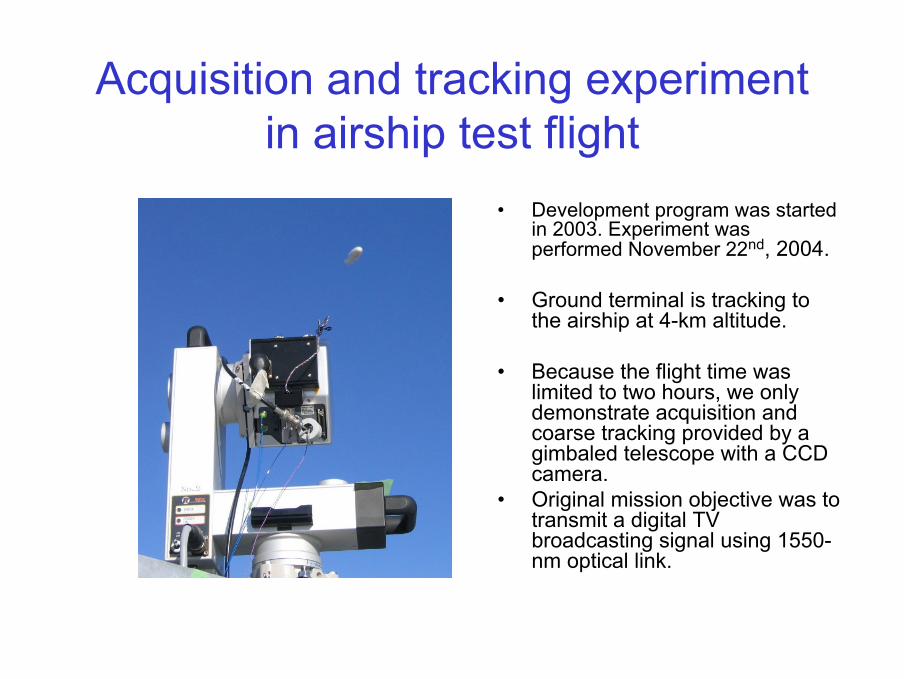
Acquisition and tracking experimentin airship test flight
• Development program was started in 2003. Experiment was performed November 22nd, 2004.
• Ground terminal is tracking to the airship at 4-km altitude.
• Because the flight time was limited to two hours, we only demonstrate acquisition and coarse tracking provided by a gimbaled telescope with a CCD camera.
• Original mission objective was to transmit a digital TV broadcasting signal using 1550-nm optical link.

Beacon tracking experiment
Before beacon acquisition After beacon acquisition
• Bi-directional acquisition and tracking at both onboard and ground laser communication terminals has been successfully performed. Two-axis gimbals are controlled based on the centroid of the CCD sensor shown as cross cursor.
• Tracking error (error between predicted pointing angle and real tracking angle) was less than 0.5 degrees.
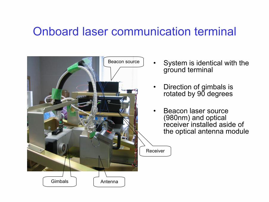
Onboard laser communication terminal
• System is identical with the ground terminal
• Direction of gimbals is rotated by 90 degrees
• Beacon laser source (980nm) and optical receiver installed aside of the optical antenna module
Antenna
Receiver
Beacon source
Gimbals

Configuration of ground terminalSignal beam and beacon
(1550nm, 980/970nm)
Beacon(980nm)
Antenna and two-axis gimabs
(40mm)
Beacon Txantenna(5mmx4)
Acquisition controller
Beacon source
CCDsensor
Filter(970nm)
Er-doped fiber amplifier
Fiber coupler
LN SSB modulator
Filter(970nm)
Fast steering mirror
Quadrant APD
Tracking controller
Digital broadcasting TV signal(UHF)
Ground stationDFB laser
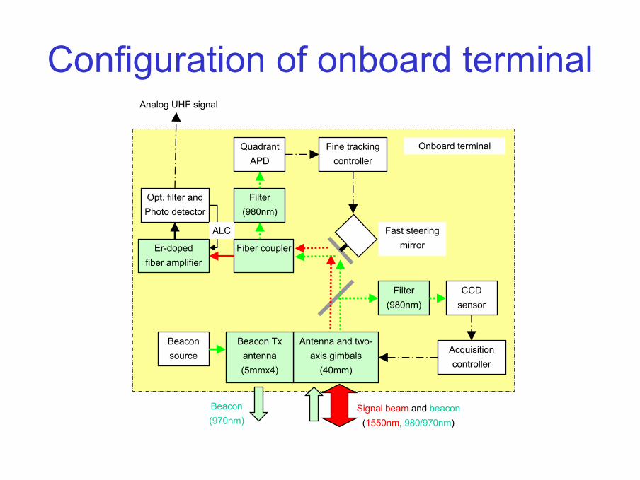
Configuration of onboard terminal
Antenna and two-axis gimbals
(40mm)
Er-dopedfiber amplifier
Opt. filter andPhoto detector
Beacon source
Beacon Txantenna(5mmx4)
Fiber coupler
CCD sensor
Filter(980nm)
Filter(980nm)
QuadrantAPD
Analog UHF signal
Fine trackingcontroller
Fast steering mirror
Acquisition controller
Signal beam and beacon(1550nm, 980/970nm)
Beacon(970nm)
Onboard terminal
ALC

Antenna module and two-axis gimbalsBeacon collimator
Fiber coupler
Collimate mirror
Primary
SecondaryFPM
External view of antenna module and two-axis gimbals
Internal layout of antenna module· Three plastic off-axis aspherical mirror are used to realize compact and light
weight optics. Effective antenna aperture is 4 cm.· Antenna module weight: 2.4kg, Gimbals weight: 9kg.

Design of off-axis aspherical mirror
Secondary(aspherical) FPM
Primary(aspherical)
Collimate mirror
tofiber coupler
CCD
QD
BS2
primary
Secondary
Collimate mirror(aspherical)
tofiber coupler
(a) Side view (b) Top view
BS1

Primary specificationLink distance: 200 m (min.), 4.6 km (max.)Elevation angle: more than 53 degrees (acquisition), more than 60 degrees (communication)Laser wavelength: 1.562 µm (uplink communication)
0.98 µm (uplink beacon), 0.97µm (downlink beacon)Output power: within class 3A (safe without optical instrument)Antenna size: 4cm in diameter (1.5 µm TX/RX), 0.5cm in diameter x 4(0.98µm beacon TX)Gimbal angle: +/- 45 degrees (Az), +/- 45 degrees (El), through windowGimbal performance: speed: 2 degrees/sec, accuracy: 0.01degreeAcquisition FOV: 0.9 degrees (diagonal), using Si-CCDBeacon beam width: 2 degrees (uplink), 0.5 degrees (down link) Weight: less than 26 kg including antenna, acquisition tracking system and receiverPower consumption: less than 70 WNumber of flight: 2 (days, expected)
Link procedure: maintain beacon tracking from the initial ascent till the height is bellow 200 m.try to make a communication link if the elevation angle is more than 60 deg.
Data processing: predict the pointing angle for both onboard and ground terminalsbased on the online telemetry data for an initial acquisition and re-acquisition.

Link budgetOptical feeder link
Wavelength: 1552nmOutput power: 100mW (+20dBm)Antenna diameter: 40mmBeam divergence: 49.4µradianLink distance: 4.6kmElevation angle: 60degreesRx beam diameter: 24.6cmFree-space loss: -15.8dBTurbulence loss: -4.4dB (unavailability 10-9,
Tracking error: 5µrad.)Inner optics loss: -6.8dBReceiving power: -7.0dBmMin. required power: -24.0dBm (C/N>40dB)Link margin: 17.0dB
Beacon link
Wavelength: 980/970nmOutput power: 50mW (+17dBm)Antenna diameter: 5mmBeam divergence: 2degreesLink distance: 4.6kmElevation angle: 60degreesRx beam diameter: 159mFree-space loss: -72.0dB (40mm diameter)Turbulence loss: -3.9dB (unavailability10-9)Receiving power: -58.9dBmMin. required power: -79.6dBm (CCD),
-60.0dBm (Quad. APD)(at the antenna aperture)
Link margin: 20.7dB(CCD)/1.1dB(APD)
(Test flight of the airship was to be performed under the clear sky condition because the pilot should control the airship from the ground using TT&C link.)

Data4 (Elevation)
-2
-1.5
-1
-0.5
0
0.5
1
1.5
2
15:0
1:1
8
15:0
2:1
9
15:0
3:2
0
15:0
4:2
2
15:0
5:2
3
15:0
6:2
4
Ship crossing
Ship crossing
Ground demonstration experimentOptical part
Electrical part
First fiber-to-fiber stable optical link was demonstrated in Waseda University campus at 1-km link distance.
Tracking error history at the ship to coast optical link experiment.

Fiber optic key componentsfor space laser communication
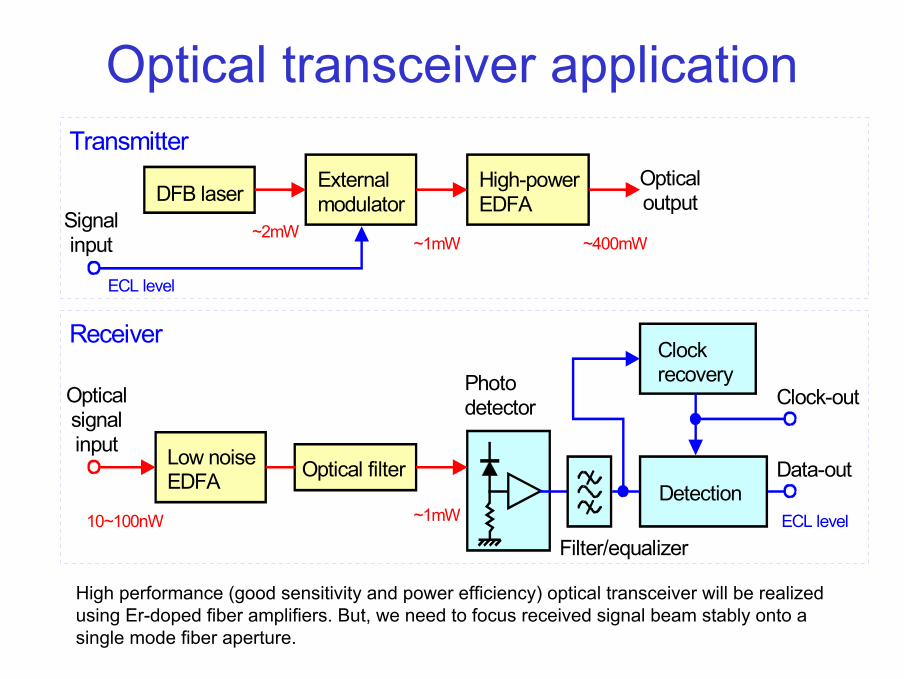
Optical transceiver application
Detection
Low noiseEDFA Optical filter
ClockrecoveryPhoto
detector
Filter/equalizer
Opticalsignalinput
Clock-out
Data-out
Receiver
Transmitter
DFB laser External modulator
High-powerEDFA
Signalinput
Opticaloutput
~1mW ~400mW~2mW
ECL level
ECL level~1mW10~100nW
High performance (good sensitivity and power efficiency) optical transceiver will be realized using Er-doped fiber amplifiers. But, we need to focus received signal beam stably onto a single mode fiber aperture.

Configuration of high-power EDFA
Optical signal input Optical signal output
Optical IsolatorSignal/Pump WDMCoupler
Optical IsolatorSignal/Pump WDM couplerEDF
Output monitor
Monitor coupler
8ch. HPU 8ch. HPU
High-power pumping unit
High-power pumping unit
Forward pumping
Backward pumping

High power EDFA- Power efficiency improvement -
Relationship between the power consumption and EDFA output power
Relationship between the power consumption efficiency and EDFAoutput power
Using cooler less pumping laser (FBG wavelength stabilized), an 8% wall plug efficiency had been achieved.
Improvement of the efficiency in driving circuit will be required (PWM, switching regulator, serial connection of pumping LDs).

Short pulse signaling of 1550-nm laser
Optical signal before the high-power EDFA. Transmitting 27-1 PN sequence with the data rate of 2.5 Gbps. LN external modulator is used.
Optical signal after the Low-noise EDFA. ASE (amplified spontaneous emission) increases shot noise, but, there is no waveform distortion.

Bit error rate measurement for LCDE BBMs1.0E-2
1.0E-3
1.0E-4
1.0E-5
1.0E-6
1.0E-7
1.0E-81.0E-9
1.0E-101.0E-11
-51.0 -50.0 -49.0 -48.0 -47.0 -46.0 -45.0 -44.0 -43.0 -42.0 -41.0
Bit
Erro
r Rat
e
Receiving level (dBm)
Minimum-BER threshold:54photons/bitDPSK 2.488Gbps by NECLCDEspec: 90photons/bit at BER=1e-9
NEW_BBM(2002.3.19):2.5GbpsRZ(108ps),ERFA2522-CRL3NEW_BBM(2002.4.8):2.5GbpsRZ(72ps),,KPS-OEM/CRL2NEW_BBM(2002.4.8):2.5GbpsRZ(72ps),,KPS-OEM/CRL4
MOD_BBM(2001.6.13): BBM_RZ(75ps)MOD_BBM(2001.6.13): 10GbpsNRZ, EDFA-AGCMOD_BBM(2001.6.18):10GbpsNRZ,EDFA-GfixMOD_BBM(2001.6.18):10GbpsRZ,EDFA-AGC
54 photons/bit
Transceiver performance improvements
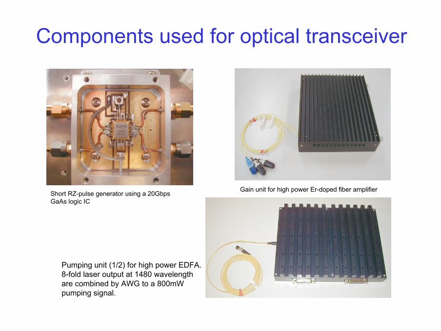
Components used for optical transceiver
Short RZ-pulse generator using a 20Gbps GaAs logic IC
Gain unit for high power Er-doped fiber amplifier
Pumping unit (1/2) for high power EDFA. 8-fold laser output at 1480 wavelength are combined by AWG to a 800mW pumping signal.
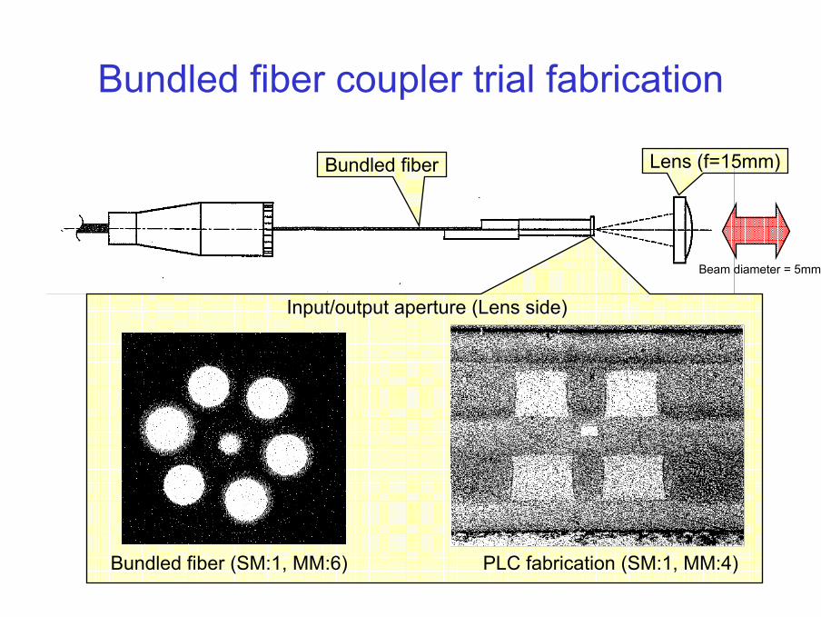
Bundled fiber coupler trial fabrication
Input/output aperture (Lens side)
Bundled fiber (SM:1, MM:6) PLC fabrication (SM:1, MM:4)
Lens (f=15mm)Bundled fiber
Beam diameter = 5mm

Bundle fiber response (Horizontal tilt)
-50
-40
-30
-20
-10
0
-1.2 -1 -0.8 -0.6 -0.4 -0.2 0 0.2 0.4 0.6 0.8 1
Beam offset [mrad.]
Rec
eive
inte
nsity
[dB
m]
SM1A1B1C1D1SM2A2B2C2D2SM3A3B3C3D3
Performance of bundled fiber coupler
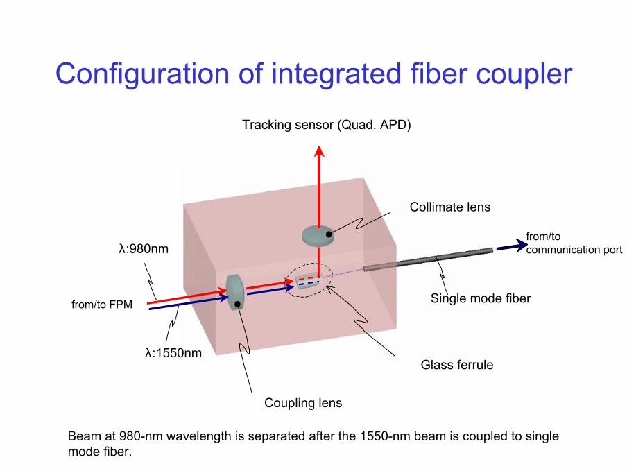
Configuration of integrated fiber coupler
λ:980nmfrom/tocommunication port
Tracking sensor (Quad. APD)
λ:1550nm
from/to FPM
Glass ferrule
Coupling lens
Collimate lens
Single mode fiber
Beam at 980-nm wavelength is separated after the 1550-nm beam is coupled to single mode fiber.

Principle of integrated fiber coupler
Single mode fiber
HR coating (mirror)
Glass ferrule
AR coating (980nm)
AR coating (980/1550nm)
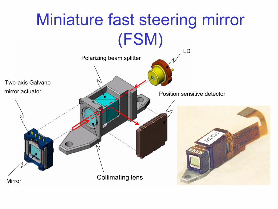
LD
Position sensitive detector
Polarizing beam splitter
Collimating lens
Two-axis Galvanomirror actuator
Mirror
Miniature fast steering mirror (FSM)

FSM frequency response
Measurement result with a PID position servo system
( Gain/phase response of miniature fast steering mirror)
Azimuth
-80
-60
-40
-20
0
20
40
60
10 100 1000 10000
Frequency [Hz]
Gai
n [d
B]
-210
-180
-150
-120
-90
-60
-30
0
Phas
e [D
egre
e]
Gain
Phase
Elevation
-80
-60
-40
-20
0
20
40
60
10 100 1000 10000
Frequency [Hz]
Gai
n [d
B]
-210
-180
-150
-120
-90
-60
-30
0
Phas
e [D
egre
e]
Gain
Phase
Azimuth
Elevation

Acquisition performance of FSM/QAPD fine tracking mode
Azimuth axis Elevation axis
QAPD power
Error Error
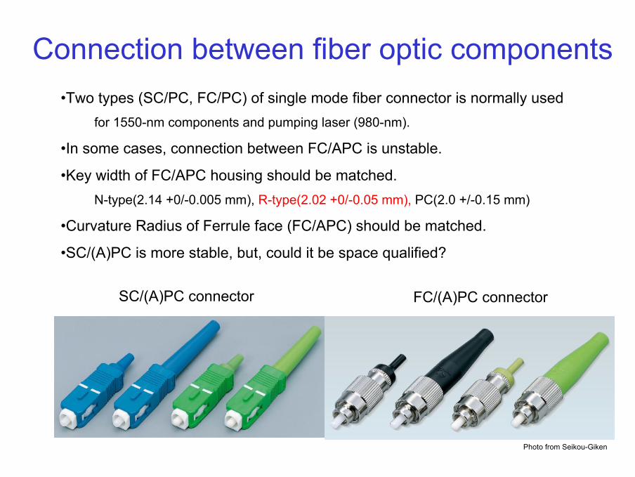
Connection between fiber optic components
SC/(A)PC connector FC/(A)PC connector
Photo from Seikou-Giken
•Two types (SC/PC, FC/PC) of single mode fiber connector is normally usedfor 1550-nm components and pumping laser (980-nm).
•In some cases, connection between FC/APC is unstable.
•Key width of FC/APC housing should be matched.N-type(2.14 +0/-0.005 mm), R-type(2.02 +0/-0.05 mm), PC(2.0 +/-0.15 mm)
•Curvature Radius of Ferrule face (FC/APC) should be matched.
•SC/(A)PC is more stable, but, could it be space qualified?

Conclusion• New technologies/components were developed and evaluated at
NICT to realize compact laser communication terminals for future space laser communication system.
• To couple free-space laser beam into single mode fiber is still difficult, but, tracker-integrated fiber coupler will be used in the near future.
• Fiber optics might be used for broadband (millimeter wave) satellite transponder based on Radio-On-Fiber technology for the future.
• Key components to build a fiber optic transceiver, such as LN external modulator, tunable optical filter are under evaluation at NICT.