Fiber Network Topologies Connecting VDSL Networks - · PDF fileVery high speed Digital...
22
HELSINKI UNIVERSITY OF TECHNOLOGY Department of Electrical and Communications Engineering Laboratory of Telecommunications Technology Fiber Network Topologies Connecting VDSL Networks S-38.128 Special Assignment (2 cr) Written by: Harri Mäntylä, 36491N Supervisor: Vesa Kosonen Returned: 27.8.1999
Transcript of Fiber Network Topologies Connecting VDSL Networks - · PDF fileVery high speed Digital...
HELSINKI UNIVERSITY OF TECHNOLOGY
Department of Electrical and Communications Engineering
Laboratory of Telecommunications Technology
Fiber Network Topologies Connecting VDSL Networks
S-38.128 Special Assignment (2 cr)
Written by: Harri Mäntylä, 36491N
Supervisor: Vesa Kosonen
Returned: 27.8.1999
2
Table of Contents
Table of Contents ...........................................................................................................2
Abbreviations .................................................................................................................3
1. Introduction............................................................................................................5
2. Digital Subscriber Line (DSL) technologies..........................................................6
2.1 ISDN ..................................................................................................................6
2.2 HDSL .................................................................................................................6
2.3 HDSL2 ...............................................................................................................7
2.4 ADSL .................................................................................................................7
2.5 ADSL Lite..........................................................................................................7
2.6 VDSL .................................................................................................................8
2.6.1 Standardization...........................................................................................8
2.6.2 Defined Data Rates ....................................................................................8
2.6.3 Required Network Topology......................................................................9
2.6.4 Connecting of ONUs to Backbone...........................................................10
2.6.5 Obstacles ..................................................................................................10
3. Access network topology.....................................................................................11
3.1 Current Topology.............................................................................................11
3.2 Access Network Model ....................................................................................12
4. Network topologies ..............................................................................................14
5. Fiber network topology of the AN model............................................................17
6. Conclusions..........................................................................................................20
References....................................................................................................................21
3
Abbreviations
ADSL Asymmetric Digital Subscriber Line
ADSL Lite Asymmetric Digital Subscriber Line, light version
AN Access Network
ANSI American National Standards Institute
BRI Basic Rate Interface
CAP Carrierless Amplitude-Phase Modulation
DMT Discrete Multitone
DP Distribution Point
DSL Digital Subscriber Line
DSLAM DSL Access Multiplexer
E1 connections European basic multiplex rate of 2.048 Mbit/s
ETSI European Telecommunication Standards Institute
FP1 Flexibility Point 1, primary crossconnection
FP2 Flexibility Point 2, secondary crossconnection
FTABCDE Fiber to A, B, C, D and E, in the access network model
FTTC Fiber to the Curb
FTTLex Fiber to the Local exchange
HDSL High bit rate DSL
HDSL2 High bit rate DSL, second upgraded version
ISDN Integrated Services Digital Network
ITU International Telecommunications Union
LE Local Exchange
LT Line Termination
MDF Main Distribution Frame
NT Network Termination
OLT Optical Line Terminal
ONU Optical Network Unit
PBX Private Branch eXchange
POTS Plain Old Telephony Service
QAM Quadrature Amplitude Modulation
TE Terminal Equipment
4
U-ADSL Universal Asymmetric Digital Subscriber Line
UDSL Universal Digital Subscriber Line
UNIs User Network Interfaces
VoD Video on Demand
VDSL Very high speed Digital Subscriber Line
xDSL Generic term covering all Digital Subscriber Line technologies
5
1. Introduction
Very-high speed Digital Subscriber Line (VDSL) technology utilizes the final few
hundred meters of the existing twisted copper pairs for broadband data transmission.
Introduction of VDSL into the present copper access network requires radical changes
to the network topology, since the remaining copper loop length needs to be shortened
significantly. From the present Fiber to the Local exchange (FTTLex) architecture a
transition to Fiber to the Curb (FTTC) architecture will have to be made. This means
that fiber end points also called Optical Network Units (ONU) containing active
electronics are placed in the approximate vicinity of the subscribers. New fiber network
needs to be built in order to connect ONUs to data networks. There are some options
concerning the topology of this fiber network. Especially when the number of ONUs is
big and the fiber reaches close to end-users the applied fiber topology starts to be
important. Additional fiber links may be required for protection. The present topology
of the telephone access network may be inadequate for the new active devices.
This paper is a continuation of the work done with my master’s thesis [Män99].
Background material presented in chapters 2 and 3 is partly based on the material of the
master’s thesis. The other chapters consist of completely new material that is not
covered by the thesis.
6
2. Digital Subscriber Line (DSL) technologies
DSL or xDSL is a general term for digital technologies utilizing more of the
transmission capacity of the twisted copper pair than the analog telephone systems have
used so far. Analog connections only use the audible spectra of 4 kHz, which is just a
fraction of the entire spectra transmittable over copper pair [Hum97].
In the following standardized technologies and the ones being standardized are
presented. In addition to these there is a number of other proprietary DSL solutions
from various companies that are not presented here.
2.1 ISDN
The digitalization of the telephone access network formed of passive twisted copper
pairs began with ISDN that was developed in the 1980’s. The basic rate ISDN (BRI)
consists of two 64 kbit/s B channels for voice or data and one 16 kbit/s D channel for
signaling (2B+D). By using both B channels 128 kbit/s data rate is achieved, about three
or four times more than is achieved with analogue modems. At the moment ISDN is a
good choice for residential users who need a faster, but still economical, connection.
For bandwidth hungry multimedia services the transmission capacity of ISDN is too
low. Newer DSL technologies, developed during the 1990’s, offer significantly higher
data rates.
2.2 HDSL
High bit rate DSL is the most widely deployed DSL technology that has been available
since the beginning of the 1990’s. HDSL offers a symmetrical 2 Mbit/s connection over
two or three copper pairs. Typically HDSL is used to transmit 2048 Mbit/s E1
connections over two copper pairs. With HDSL the provisioning of E1 connections is
cheaper than with older technologies. HDSL operating distance is about 3.5 km over 0.5
mm cable depending on the cable quality [Che98].
7
2.3 HDSL2
HDSL2 is developed from HDSL to offer the same service as HDSL does but over a
single copper pair. The achieved operating distance is about 3 km, slightly shorter than
that of HDSL [Che98].
2.4 ADSL
Asymmetric DSL was originally intended for providing video-on-demand (VoD)
services to residential subscribers. Later Internet usage became the driving force for
ADSL as it was realized that highly asymmetric data rates provided by ADSL are ideal
for loading multimedia content from the Internet. Offered range of data rates in the
downstream direction varies from 1 to 8 Mbit/s and in the upstream from 16 to
800 kbit/s. The operating distance may be up to 5 km depending on the quality of the
cable. This long operating distance makes it possible to apply ADSL to the existing
network without changes to access network topology.
ADSL modems are standardized to be rate adaptive so that it is possible to adapt the
data rate according to line conditions. For residential users an important feature of
ADSL is that it may be used simultaneously over the same copper pair with existing
POTS or even ISDN if necessary. So called POTS splitters are required to separate the
POTS and ADSL signals from each other. ISDN friendly mode of ADSL means a small
decrease in achieved data rate since part of the bandwidth is reserved for ISDN [Rau99],
[Dix99], [Max96], [Poi96].
2.5 ADSL Lite
ADSL Lite also known as Universal DSL (UDSL) or Universal Asymmetric DSL
(U-ADSL) is a lower data rate version of ADSL. ADSL Lite is designed to be a mass
market consumer version of ADSL and is supposed to work without the splitter in the
customer premises making the installation process simpler. Some doubts have been
expressed on the splitterless solution as the quality of POTS connection could be
worsened too much [Dix99].
8
2.6 VDSL
Very high speed Digital Subscriber Line technology and especially the fiber network
topologies connecting VDSL networks is the topic of this paper. Therefore VDSL
technology is in the following presented in more detail than the previously presented
other DSL technologies.
2.6.1 Standardization
VDSL is currently being standardized in ITU, ANSI and ETSI. Although many standard
bodies are involved in the process, close co-operation is being done and the goal is to
accomplish a common standard during this year.
The main issue in the standardization process at the moment is the choosing of VDSL
line code. There are two candidate proposals, which are supported by two equally strong
groups formed of participating companies. Single carrier technologies (CAP and QAM)
are promoted by the so-called VDSL coalition group. The VDSL alliance group is the
opposing group supporting discrete multitone (DMT) technology as the line code. There
is strong disagreement between these two groups on which should be selected.
DMT is more complex to realize of these two, and therefore it seems that single carrier
modems could be brought to the market faster if a single carrier was chosen as a
standard. The performance of the two line codes is about the same and it seems that the
disagreement is more of political nature than of technical. Big companies are behind
each line code and big investments have already been made in these companies for the
line code that they are supporting.
2.6.2 Defined Data Rates
VDSL technology is intended for transmitting high-speed data over short lengths of
twisted copper pair. The bandwidth to be used by VDSL reaches up to 30 MHz,
although the highest frequencies are usable only over very short cables.
Somewhat different VDSL data rates are presented in various standard proposals and
drafts. Downstream rates going up to 52 Mbit/s and upstream ones up to 34 Mbit/s are
suggested in [VDS98a], [VDS98b], [ANS98]. In Table 1 the payload bit-rates defined
in the newest ETSI specification are presented.
9
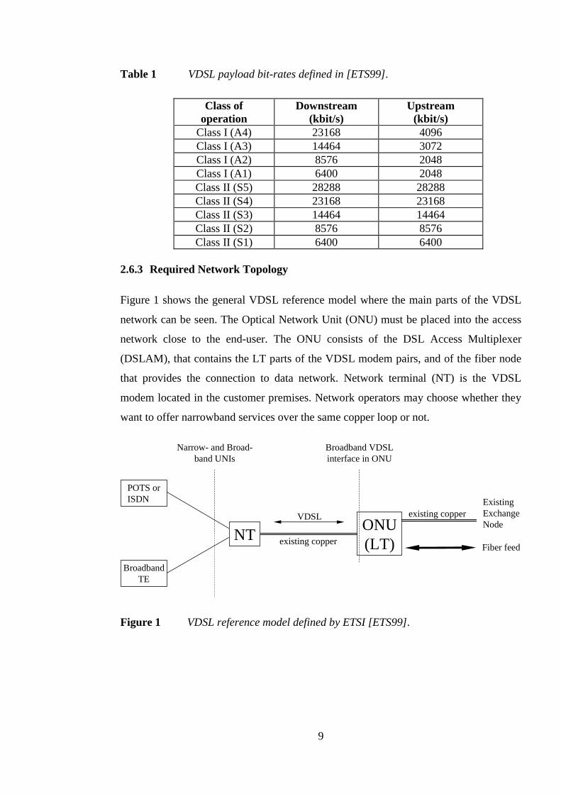
Table 1 VDSL payload bit-rates defined in [ETS99].
Class ofoperation
Downstream(kbit/s)
Upstream(kbit/s)
Class I (A4) 23168 4096Class I (A3) 14464 3072Class I (A2) 8576 2048Class I (A1) 6400 2048Class II (S5) 28288 28288Class II (S4) 23168 23168Class II (S3) 14464 14464Class II (S2) 8576 8576Class II (S1) 6400 6400
2.6.3 Required Network Topology
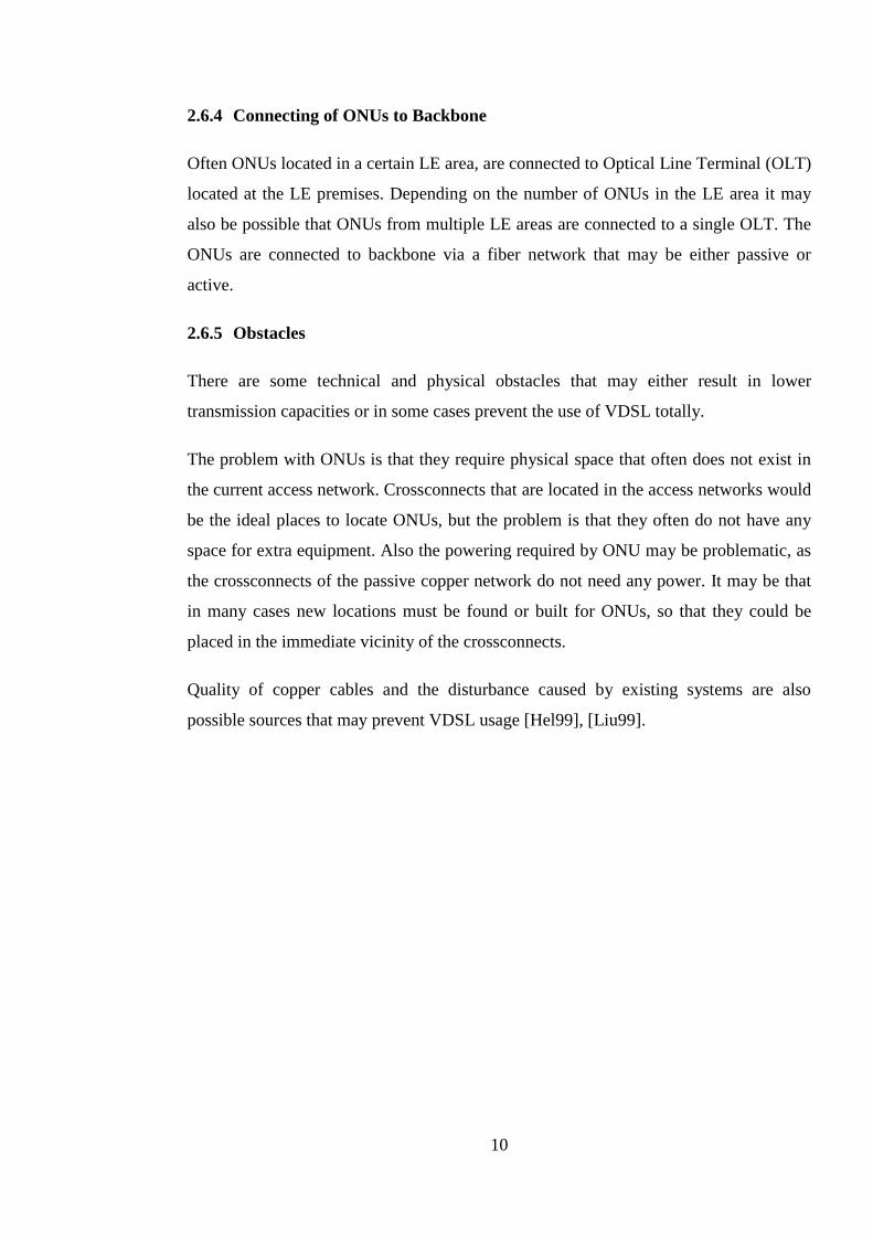
Figure 1 shows the general VDSL reference model where the main parts of the VDSL
network can be seen. The Optical Network Unit (ONU) must be placed into the access
network close to the end-user. The ONU consists of the DSL Access Multiplexer
(DSLAM), that contains the LT parts of the VDSL modem pairs, and of the fiber node
that provides the connection to data network. Network terminal (NT) is the VDSL
modem located in the customer premises. Network operators may choose whether they
want to offer narrowband services over the same copper loop or not.
NTONU(LT)
VDSL existing copperExistingExchangeNode
Fiber feed
Broadband VDSLinterface in ONU
Narrow- and Broad-band UNIs
POTS orISDN
BroadbandTE
existing copper
Figure 1 VDSL reference model defined by ETSI [ETS99].
10
2.6.4 Connecting of ONUs to Backbone
Often ONUs located in a certain LE area, are connected to Optical Line Terminal (OLT)
located at the LE premises. Depending on the number of ONUs in the LE area it may
also be possible that ONUs from multiple LE areas are connected to a single OLT. The
ONUs are connected to backbone via a fiber network that may be either passive or
active.
2.6.5 Obstacles
There are some technical and physical obstacles that may either result in lower
transmission capacities or in some cases prevent the use of VDSL totally.
The problem with ONUs is that they require physical space that often does not exist in
the current access network. Crossconnects that are located in the access networks would
be the ideal places to locate ONUs, but the problem is that they often do not have any
space for extra equipment. Also the powering required by ONU may be problematic, as
the crossconnects of the passive copper network do not need any power. It may be that
in many cases new locations must be found or built for ONUs, so that they could be
placed in the immediate vicinity of the crossconnects.
Quality of copper cables and the disturbance caused by existing systems are also
possible sources that may prevent VDSL usage [Hel99], [Liu99].
11
3. Access network topology
VDSL networks are typically built over existing copper access networks. Fiber is
brought to the certain point in the access network and the final hop to the subscriber is
realized with VDSL over existing copper pair. This chapter begins with the presentation
of the topology of current copper access network after which the access network model
is presented.
3.1 Current Topology
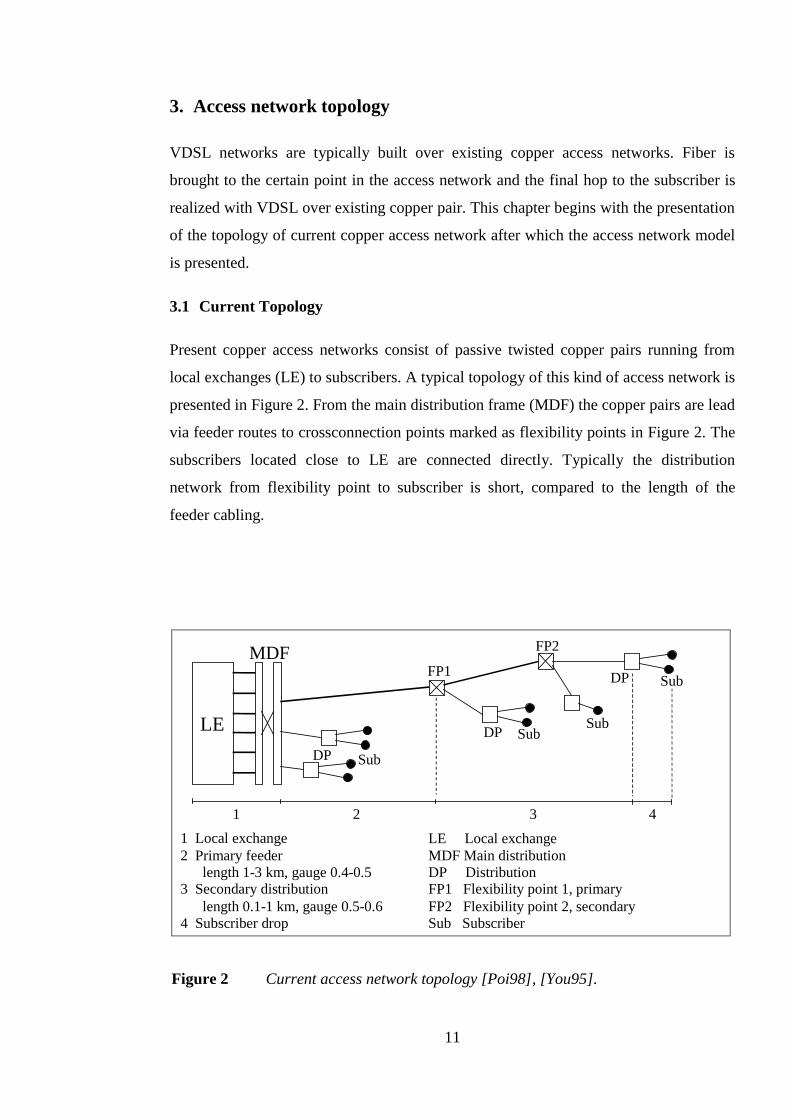
Present copper access networks consist of passive twisted copper pairs running from
local exchanges (LE) to subscribers. A typical topology of this kind of access network is
presented in Figure 2. From the main distribution frame (MDF) the copper pairs are lead
via feeder routes to crossconnection points marked as flexibility points in Figure 2. The
subscribers located close to LE are connected directly. Typically the distribution
network from flexibility point to subscriber is short, compared to the length of the
feeder cabling.
LE
MDF
DP
DP
DPFP1
FP2
Sub
Sub
Sub
LE Local exchangeMDF Main distributionDP DistributionFP1 Flexibility point 1, primaryFP2 Flexibility point 2, secondarySub Subscriber
Sub
1 2 3 4
1 Local exchange2 Primary feeder
length 1-3 km, gauge 0.4-0.53 Secondary distribution
length 0.1-1 km, gauge 0.5-0.64 Subscriber drop
Figure 2 Current access network topology [Poi98], [You95].
12
3.2 Access Network Model
Access network models make it possible to perform calculations and evaluations of
different upgrade scenarios in a simplified environment where all the needed parameters
are known unlike in the real network. Different models have been developed for
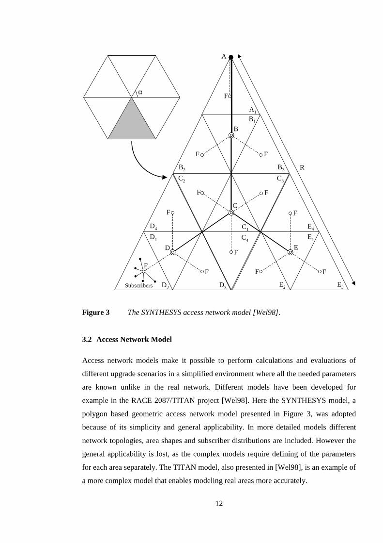
example in the RACE 2087/TITAN project [Wel98]. Here the SYNTHESYS model, a
polygon based geometric access network model presented in Figure 3, was adopted
because of its simplicity and general applicability. In more detailed models different
network topologies, area shapes and subscriber distributions are included. However the
general applicability is lost, as the complex models require defining of the parameters
for each area separately. The TITAN model, also presented in [Wel98], is an example of
a more complex model that enables modeling real areas more accurately.
A
C
B
D E
Subscribers
F
FF
F F
F
F
FFF
F
F
A1
B1
B3B2
C2 C3
C4
C1
D1
D4
D2 D3 E2 E3
E4
E1
α
R
Figure 3 The SYNTHESYS access network model [Wel98].
13
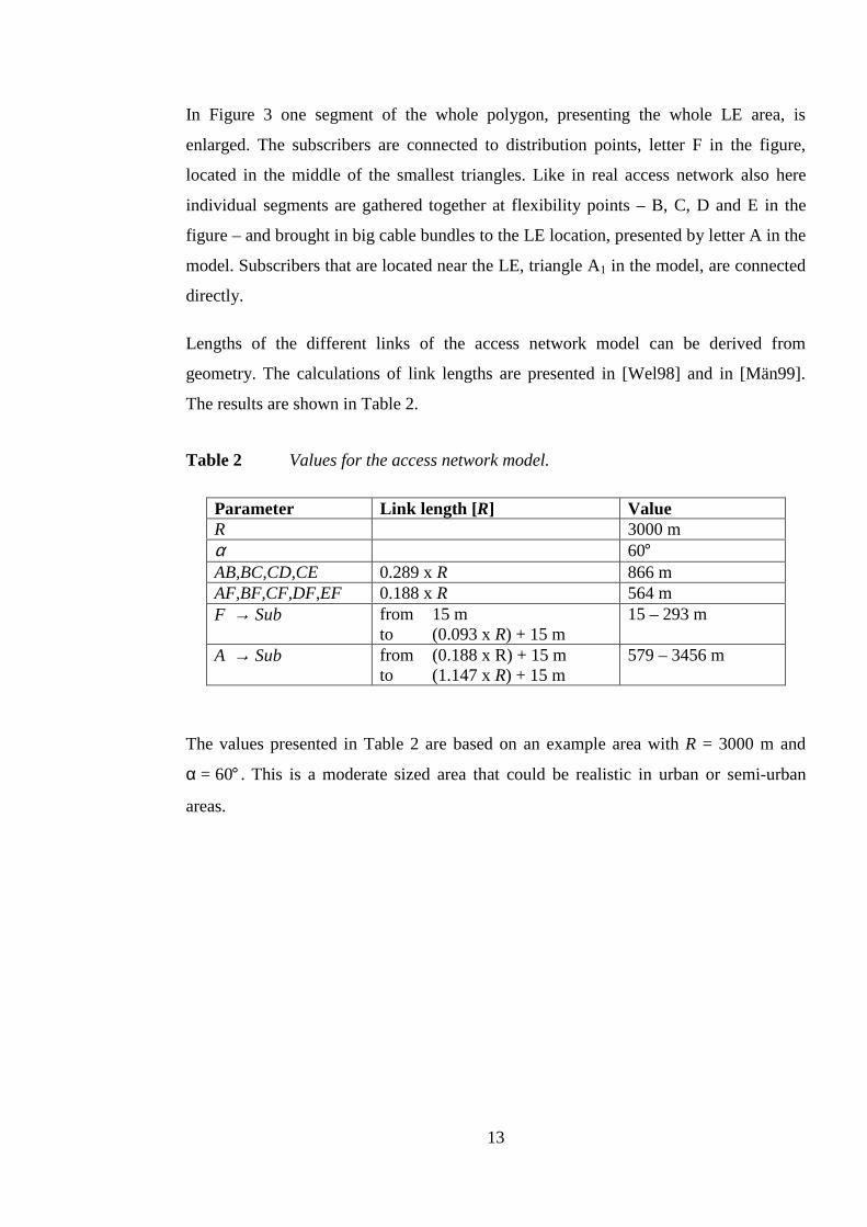
In Figure 3 one segment of the whole polygon, presenting the whole LE area, is
enlarged. The subscribers are connected to distribution points, letter F in the figure,
located in the middle of the smallest triangles. Like in real access network also here
individual segments are gathered together at flexibility points – B, C, D and E in the
figure – and brought in big cable bundles to the LE location, presented by letter A in the
model. Subscribers that are located near the LE, triangle A1 in the model, are connected
directly.
Lengths of the different links of the access network model can be derived from
geometry. The calculations of link lengths are presented in [Wel98] and in [Män99].
The results are shown in Table 2.
Table 2 Values for the access network model.
Parameter Link length [R] ValueR 3000 mα 60°AB,BC,CD,CE 0.289 xR 866 mAF,BF,CF,DF,EF 0.188 xR 564 mF → Sub from 15 m
to (0.093 xR) + 15 m15 – 293 m
A → Sub from (0.188 x R) + 15 mto (1.147 xR) + 15 m
579 – 3456 m
The values presented in Table 2 are based on an example area withR = 3000 m and
α = 60° . This is a moderate sized area that could be realistic in urban or semi-urban
areas.
14
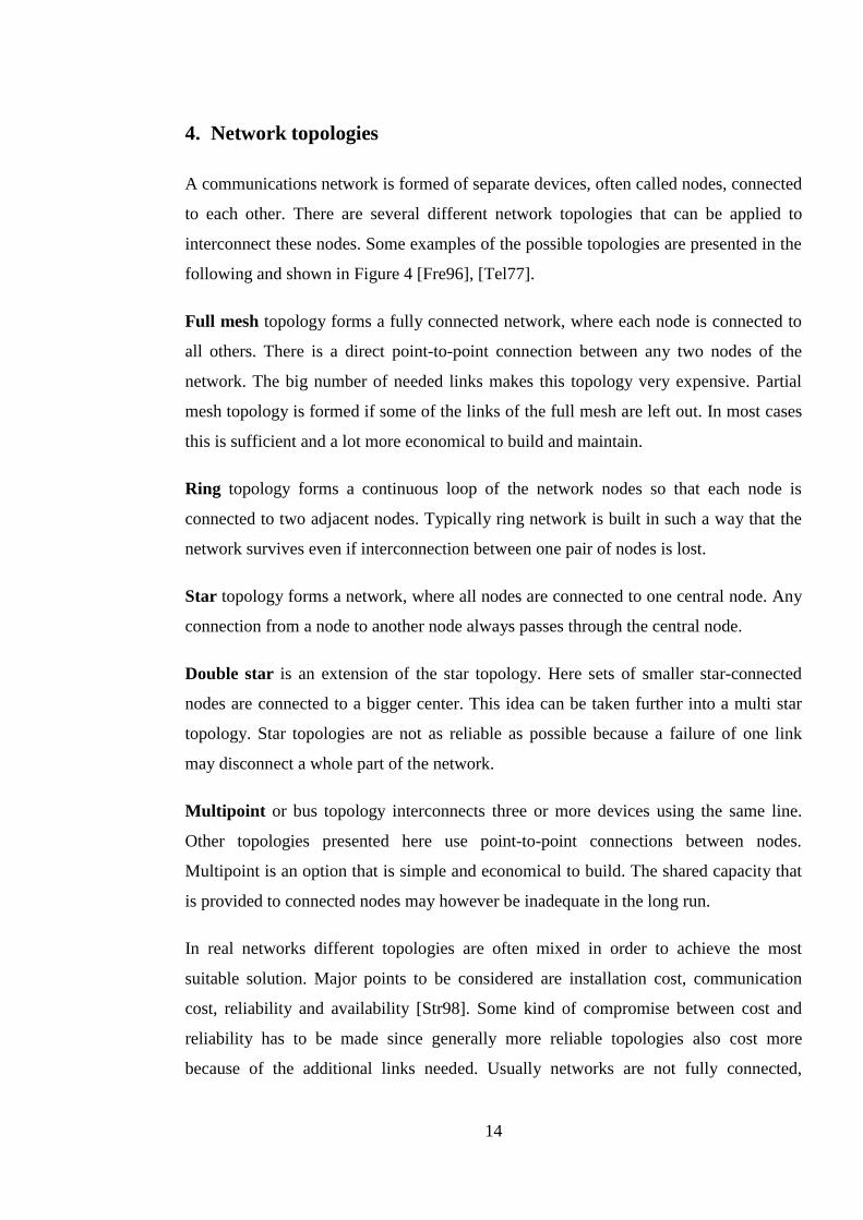
4. Network topologies
A communications network is formed of separate devices, often called nodes, connected
to each other. There are several different network topologies that can be applied to
interconnect these nodes. Some examples of the possible topologies are presented in the
following and shown in Figure 4 [Fre96], [Tel77].
Full mesh topology forms a fully connected network, where each node is connected to
all others. There is a direct point-to-point connection between any two nodes of the
network. The big number of needed links makes this topology very expensive. Partial
mesh topology is formed if some of the links of the full mesh are left out. In most cases
this is sufficient and a lot more economical to build and maintain.
Ring topology forms a continuous loop of the network nodes so that each node is
connected to two adjacent nodes. Typically ring network is built in such a way that the
network survives even if interconnection between one pair of nodes is lost.
Star topology forms a network, where all nodes are connected to one central node. Any
connection from a node to another node always passes through the central node.
Double star is an extension of the star topology. Here sets of smaller star-connected
nodes are connected to a bigger center. This idea can be taken further into a multi star
topology. Star topologies are not as reliable as possible because a failure of one link
may disconnect a whole part of the network.
Multipoint or bus topology interconnects three or more devices using the same line.
Other topologies presented here use point-to-point connections between nodes.
Multipoint is an option that is simple and economical to build. The shared capacity that
is provided to connected nodes may however be inadequate in the long run.
In real networks different topologies are often mixed in order to achieve the most
suitable solution. Major points to be considered are installation cost, communication
cost, reliability and availability [Str98]. Some kind of compromise between cost and
reliability has to be made since generally more reliable topologies also cost more
because of the additional links needed. Usually networks are not fully connected,
15
a b
c d
e
Figure 4 Examples of network topologies.
(a) full mesh
(b) ring
(c) star
(d) double star
(e) multipoint
16
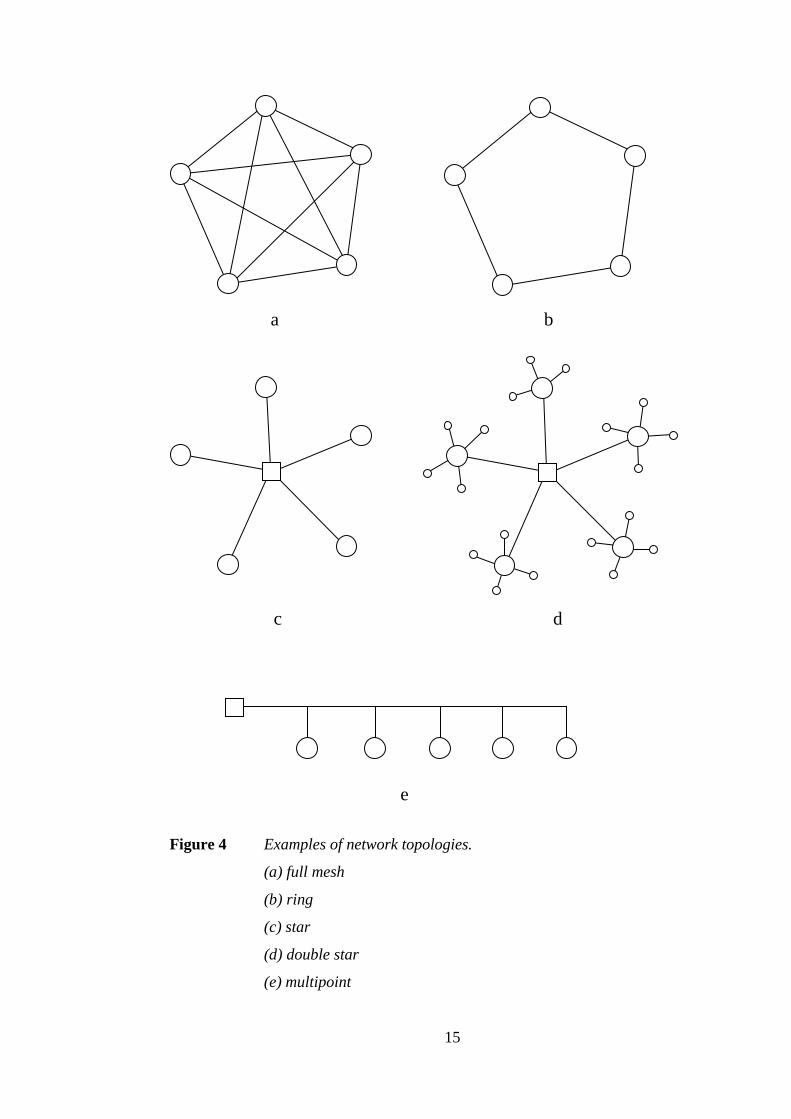
Figure 5 Physical star, logical ring topology.
although it is desirable to have more than one path through the network for each pair of
nodes
Physical and logical topologies are not always the same. An example of this is shown in
Figure 5 in which a physical star forms a logical ring. This way the number of required
connections in the center node is reduced to only two. In case of fiber networks this may
be of importance since the ending of each fiber introduces additional costs. In general
possible logical topologies that can be applied depend on the existing physical topology.
17
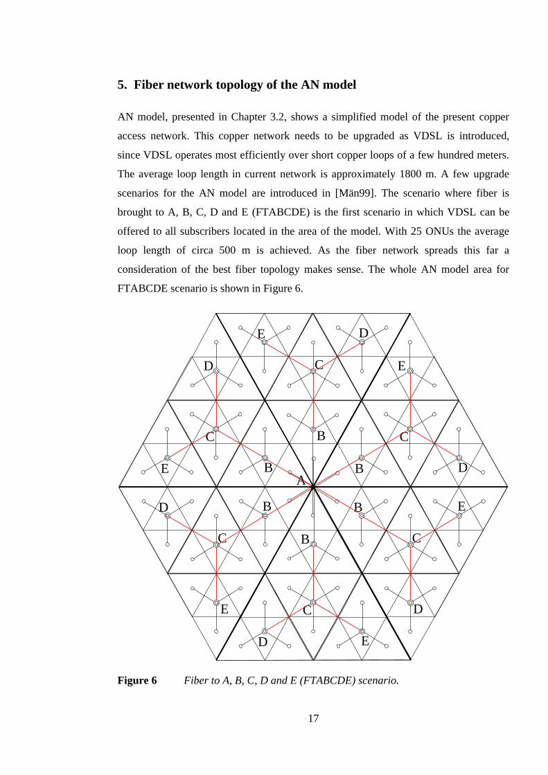
5. Fiber network topology of the AN model
AN model, presented in Chapter 3.2, shows a simplified model of the present copper
access network. This copper network needs to be upgraded as VDSL is introduced,
since VDSL operates most efficiently over short copper loops of a few hundred meters.
The average loop length in current network is approximately 1800 m. A few upgrade
scenarios for the AN model are introduced in [Män99]. The scenario where fiber is
brought to A, B, C, D and E (FTABCDE) is the first scenario in which VDSL can be
offered to all subscribers located in the area of the model. With 25 ONUs the average
loop length of circa 500 m is achieved. As the fiber network spreads this far a
consideration of the best fiber topology makes sense. The whole AN model area for
FTABCDE scenario is shown in Figure 6.
C
E
B D
C
E
BD
A
C
B
D E
C
B
DE
C
D
EB
C
D
E B
Figure 6 Fiber to A, B, C, D and E (FTABCDE) scenario.
18
In Figure 6 new fiber is routed along the existing cable paths. This is probably the most
natural way for the fiber network to be built as new fiber is placed to the same cable
paths as old copper cables. In the best case no new cable paths are required and in the
worst case the old cable paths are so full that new cables have to be dug also in this
case. The resulting topology is a star. Reliability of this type of network is not the best
possible, as the links are not protected from failures. One failure near center location –
A – could disconnect a whole segment. Possible capacity problems are also faced as all
data generated from a segment passes through one link to A.
These problems can be solved partly by using multiple fibers in each link. Fiber cables
that are installed typically contain 12, 24, 48 or possibly even more fibers. These would
be enough to have a dedicated fiber to each ONU location in FTABCDE scenario if
needed. Costs generated by a large number of fiber endings might prevent the use of
this option. Another option could be to connect nodes to a logical ring, this way the
number of fiber endings could be reduced significantly.
However, even more reliable solution would be to build crosswise links into the access
network. In the current passive access network there usually has been no need for such
links and therefore they do not exist. Connections to the PBXs of bigger companies are
an exception, because they are often secured for example by connecting them to two
separate LEs. For residential subscriber connections the paths through the access
network are usually not secured.
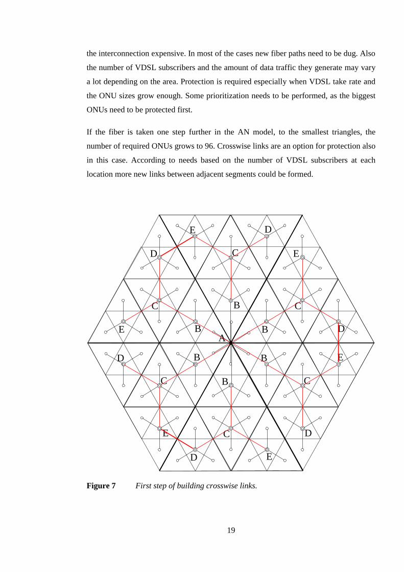
As active ONUs are placed into the access network with introduction of VDSL it is a
considerable option to build at least some crosswise links to make rerouting and
recovering from failures easier. Figure 7 shows the first crosswise links that could be
built to the network presented by AN model. Another option could be to interconnect B-
nodes from adjacent segments. As the VDSL subscriber numbers grow bigger more
crosswise links could be installed. This way rings connecting adjacent segments to each
other would be formed. As in most of the real networks also here none of the earlier
presented topologies fits this topology directly, a mixture of a star and a ring is formed.
Partial mesh network could describe the new network topology also.
In real network the building of crosswise links is not as straightforward as in the AN
model. Nodes in the adjacent segments may be separated by various obstacles, making
19
the interconnection expensive. In most of the cases new fiber paths need to be dug. Also
the number of VDSL subscribers and the amount of data traffic they generate may vary
a lot depending on the area. Protection is required especially when VDSL take rate and
the ONU sizes grow enough. Some prioritization needs to be performed, as the biggest
ONUs need to be protected first.
If the fiber is taken one step further in the AN model, to the smallest triangles, the
number of required ONUs grows to 96. Crosswise links are an option for protection also
in this case. According to needs based on the number of VDSL subscribers at each
location more new links between adjacent segments could be formed.
C
E
B D
C
E
BD
A
C
B
D E
C
B
DE
C
D
EB
C
D
E B
Figure 7 First step of building crosswise links.
20
6. Conclusions
As present copper access network is upgraded to hybrid fiber-copper network, a need
for rethinking the utilized network topology becomes important. Protection of links
connecting new active nodes placed into the access network requires additional
crosswise links that do not exist in the present network. When adjacent segments of the
access network are interconnected new rings can be formed and the reliability of the
network can be raised to a higher level.
Probably the biggest problem is the cost. Upgrading of present network is very
expensive even without extra connections required for better reliability. It must be
thought very thoroughly which sites are the most important and should therefore be
protected by additional links before other sites.
21
References
[ANS98] ANSI T1E1.4, Draft Technical Document, Revision16,Very-high-speeddigital subscriber lines, system requirements, September 1, 1999.
[Che98] Walter Y. Chen,DSL simulation techniques and standards developmentfor digital subscriber line systems, Indianapolis, IN, USA, MacmillanTechnical Publishing, 1998.
[Dix99] Sudhir Dixit, “Data rides high on high-speed remote access,”IEEECommunications Magazine, vol. 37, no. 1, Jan. 1999, pp. 130-141.
[ETS99] ETSI Technical Specification, TS 101 270-1 V1.1.5,Transmission andMultiplexing (TM); Access transmission systems on metallic accesscables; Very high speed Digital Subscriber Line (VDSL); Part 1:Functional requirements, Jun. 1999.
[Fre96] Roger Freeman,Telecommunication system engineering, USA, JohnWiley & Sons, 1996.
[Hel99] Janne Helenius,Characterisation of twisted pair cables for high speeddigital subscriber line applications, Master’s Thesis, Tampere Universityof Technology, 1999.
[Hum97] M. Humprey,et al., “How xDSL supports broadband services to thehome,”IEEE Network, vol. 11, no.1, Jan./Feb. 1997, pp. 14-23.
[Liu99] Yaohui Liu, et al., “Capacity estimation of VDSL connections based onchannel measurements,”Proc. of the 1999 Finnish signal processingsymposium (FINSIG’99), Oulu, Finland, May 31, 1999, pp. 262-266.
[Max96] K. Maxwell, “Asymmetric Digital Subscriber Line: Interim Technologyfor the Next Forty Years,”IEEE Communications Magazine, vol. 34, no.10, Oct. 1996, pp. 100-106.
[Män99] Harri Mäntylä,Design of very high speed digital subscriber line (VDSL)networks, Master’s Thesis, Helsinki University of Technology, 1999.
[Poi96] Pasi Poikolainen,Epäsymmetrinen digitaalinen tilaajajohto (ADSL)laajakaistaisena tilaajaliityntänä (= Asymmetric Digital Subscriber Line(ADSL) as a Broadband Subscriber Access, in Finnish), Master’s Thesis,Helsinki University of Technology, 1996.
[Rau99] Dennis Rauschmayer,ADSL/VDSL principles, Indianapolis, IN, USA,Macmillan Technical Publishing, 1999.
[Str98] Markus Strand,Effect of delay on network protocols report of simulatortests, Special assignment, course S-38.128, Helsinki University ofTechnology, 1998.
[Tel77] Prepared by the Research and Development Center of Standard Electrica,Telecommunication planning, Part3: Networks, Madrid, Spain,Neografis, 1977.
[VDS98a] VDSL Alliance, “VDSL Alliance DMT VDSL Draft Standard Proposal,”ETSI TM-6, TD-28, Madrid, Jan. 26-30, 1998.
22
[VDS98b] VDSL Coalition, “VDSL Coalition Technical Draft Specification,” ETSITM-6, TD-23, Antwerp, Belgium, April 20-24, 1998.
[Wel98] I. Welling et al., “Geometric models,”Broadband access networks:introduction strategies and techno-economic evaluation, edited by L. A.Ims, London, UK, Chapman & Hall, 1998, pp. 63-73.