Fiber Defender FD330 Series User Manual - Amazon S3 · PDF file · 2017-04-19Fiber...
37
Rev I PM-ENG-008 Confidential – Limited Distribution Fiber Defender FD330 Series User Manual
-
Upload
truongkien -
Category
Documents
-
view
225 -
download
2
Transcript of Fiber Defender FD330 Series User Manual - Amazon S3 · PDF file · 2017-04-19Fiber...
Rev I PM-ENG-008 Confidential – Limited Distribution
Fiber Defender
FD330 Series User Manual

Page 2 Confidential – Limited Distribution
© Copyright 2014, Fiber SenSys® all rights reserved. No part of this publication may be reproduced or transmitted in any form or by any means, electronic or mechanical, including photocopy, recording, or any information storage and retrieval system, without permission in writing from Fiber SenSys®, Inc., 2925 NW Aloclek Drive, Suite 120, Hillsboro, Oregon 97124, USA.
This manual is provided by Fiber SenSys Inc. While reasonable efforts have been taken in the preparation of this material to ensure its accuracy, Fiber SenSys Inc. makes no express or implied warranties of any kind with regard to the documentation provided herein. Fiber SenSys Inc. reserves the right to revise this publication and to make changes from time to time in the content hereof without obligation of Fiber SenSys Inc. to notify any person or organization of such revision or changes.
FD331TM, FD331-IPTM, FD332TM, FD332-IPTM is a trademark of Fiber SenSys Inc. (FSI)
Fiber SenSys® is a registered trademark of Fiber SenSys Inc.
Windows® is a registered trademark of Microsoft Corporation.
Fiber SenSys Inc. 2925 NW Aloclek Dr. Suite 120 Hillsboro, OR 97124 USA Tel: 1-503-692-4430 [email protected] www.fibersensys.com

3
Contents 1. Introduction .......................................................................................................... 4
2. Safety information ................................................................................................ 6
Safety terms .................................................................................................... 6 Electrical safety ............................................................................................... 6 Covers and panels .......................................................................................... 7 Inspection ....................................................................................................... 7 Laser radiation ................................................................................................ 7 Fiber-handling precautions .............................................................................. 7 FCC rules ........................................................................................................ 8
3. The Sensing Fiber ............................................................................................... 9
Fiber Optic Sensing ......................................................................................... 9 Sensor Cable .................................................................................................. 9 Site Design and Installation ........................................................................... 10 Connectors ................................................................................................... 10
4. The Alarm Processing Unit (APU) ...................................................................... 12
APU Description ............................................................................................ 12
5. SpectraView ...................................................................................................... 16
Using SpectraView ........................................................................................ 16 APU Parameter Editor Mode ......................................................................... 17 Realtime Mode .............................................................................................. 20
6. Integrating the APU into the Security System .................................................... 22
7. Testing and Certification .................................................................................... 23
8. Maintenance ...................................................................................................... 24
• Appendix A. Product Specifications ........................................................................ 26 • Appendix B. FD330 Series Menu Structure ............................................................ 27 • Appendix C. Warranty information .......................................................................... 36 • Appendix D. Referenced Documents ....................................................................... 37

4
1. Introduction
The Fiber SenSys FD330 Series is an electro-optical Instrument that uses optical fiber as a distributed sensor for detecting intruders attempting to breach a perimeter. The Alarm Processing Unit (APU) can be tuned to disregard non-threatening stimulus such as wind and animals; thus, reducing nuisance alarms. When an intruder is detected, the APU sends out an alert via state changes in terminal contacts that can be used to switch on lights, cameras, sirens, or to signal an alarm panel. For IP enabled units, the FD331-IP and FD332-IP, an alert is also sent out via IP/XML Ethernet communication. IP/XML communication for direct network interface allows for easy integration with any security solution.
The optical fiber-based system has been designed to be immune to the effects of Electromagnetic Interference (EMI), lightning, and Radio Frequency Interference (RFI). All FD330 Series models provide maximum effective intrusion detection through their inherent system flexibility and advanced programmability.
Because the fiber optic sensors use laser light which is intrinsically inert, the FD330 Series system can be installed safely at chemical plants, ammunition depots, or any location where the use of electricity is a concern.
RS-232 communication allows for simple setup and calibration.
A key component of the FD330 Series is its fiber optic sensor cable; this uniquely-designed cable, which is sensitive to movement, pressure, and vibration, can be routed along the fabric of a fence to detect climbing and cutting. The detection of an intruder triggers an alarm from the APU.
Some of the intrusion threats that the FD330 Series can be used to detect include:
• Fence climbing (along both the fabric and the posts)
• Fabric cutting
• Crawling underneath a fence
• Ladder assisted climbing of a fence
5
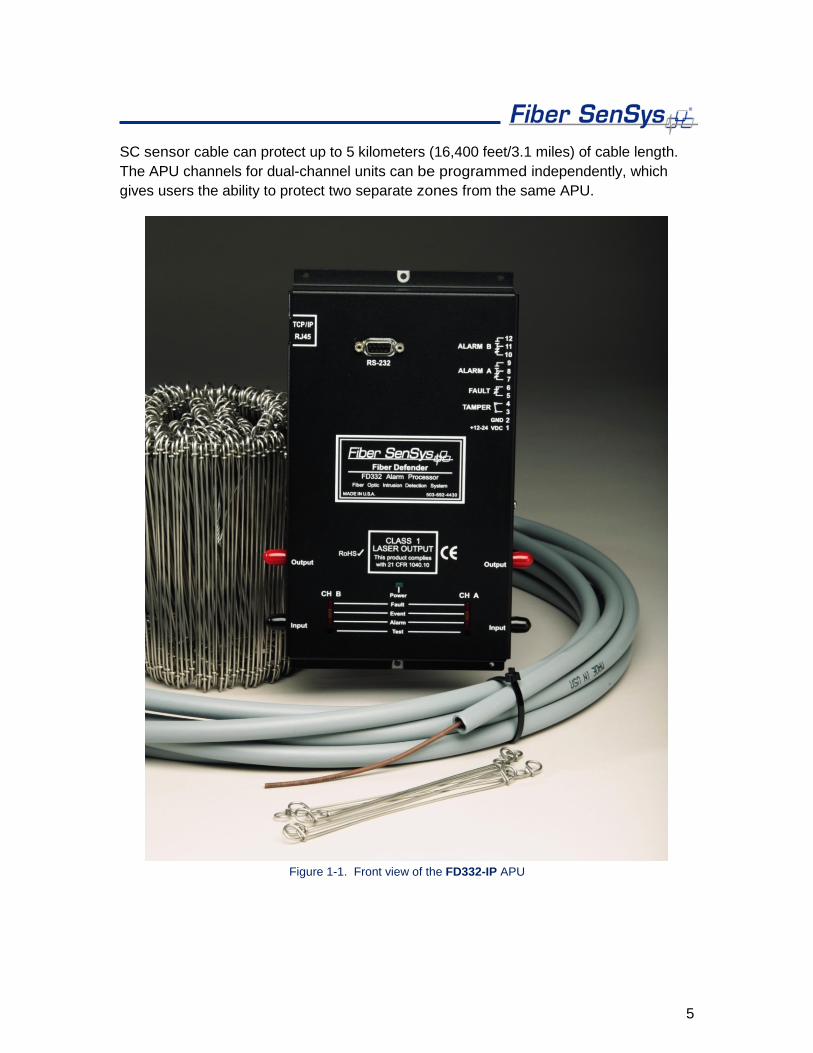
SC sensor cable can protect up to 5 kilometers (16,400 feet/3.1 miles) of cable length. The APU channels for dual-channel units can be programmed independently, which gives users the ability to protect two separate zones from the same APU.
Figure 1-1. Front view of the FD332-IP APU

6
2. Safety information
This section contains information to help ensure your personal safety and the proper operation of your equipment. Please read and follow all these instructions carefully, and keep them accessible, for future reference. Whenever using the FD330 Series, use only attachments and accessories that have been specified by FSI, and refer all servicing to qualified personnel.
Safety terms The following icons may appear throughout this manual:
CAUTION: Identifies conditions or practices that could result in damage to equipment and/or loss/contamination of data.
WARNING: Identifies conditions or practices that could result in non-fatal personal injury.
DANGER: Identifies conditions or practices that could result in serious injury or death.
Electrical safety If the FD330 Series APU is damaged or malfunctions, disconnect power to the APU. Do not use the APU if any of the following conditions exist:
• The APU is visibly damaged.
• The APU does not operate as expected.
• The APU has been subjected to prolonged storage under adverse conditions.
• The APU has been damaged during shipment.
If any of the above conditions exist, do not put the APU into service until qualified service personnel have verified its safety.
7
Covers and panels There are no user-serviceable parts inside the APU. To avoid personal injury, do not remove any of the APU’s covers or panels. The product warranty is void if the factory seal is broken. Do not operate the product unless the covers and panels are installed.
Inspection The FD330 Series APU should be inspected for shipping damage. If any damage is found, notify Fiber SenSys and file a claim with the carrier. Save the shipping container for possible inspection by the carrier.
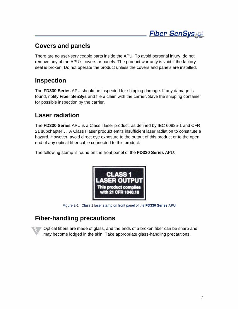
Laser radiation The FD330 Series APU is a Class I laser product, as defined by IEC 60825-1 and CFR 21 subchapter J. A Class I laser product emits insufficient laser radiation to constitute a hazard. However, avoid direct eye exposure to the output of this product or to the open end of any optical-fiber cable connected to this product.
The following stamp is found on the front panel of the FD330 Series APU:
Figure 2-1. Class 1 laser stamp on front panel of the FD330 Series APU
Fiber-handling precautions Optical fibers are made of glass, and the ends of a broken fiber can be sharp and may become lodged in the skin. Take appropriate glass-handling precautions.
8
FCC rules Note: This equipment has been tested and found to comply with the limits for a Class B digital device, pursuant to Part 15 of the FCC Rules. These limits are designed to provide reasonable protection against harmful interference in a residential installation. This equipment generates, uses, and can radiate radio frequency energy. If the equipment is not installed and used in accordance with the instructions it may cause harmful interference to radio communications. However, there is no guarantee that interference will not occur in a particular installation. If this equipment does cause harmful interference to radio or television reception, which can be determined by turning the equipment off and on, the user is encouraged to try to correct the interference by one or more of the following measures:
• Reorient or relocate the receiving antenna.
• Increase the separation between the equipment and receiver.
• Connect the equipment into an outlet on a circuit different from that to which the receiver is connected.
• Consult the dealer or an experienced radio/TV technician for help.
9
3. The Sensing Fiber
The FD330 Series detects intruders by sensing small disturbances caused by vibrations induced within a fiber optic sensor attached to the perimeter. The optical sensor is a thin strand of multimode optical fiber. The fiber optic cable should be installed in such a way that, when intruders attempt to cross the perimeter, they create slight vibrations that disturb the sensing fiber. These disturbances are then detected by the FD330 Series APU, which generates the appropriate alarm(s).
Fiber Optic Sensing When an optical fiber is exposed to vibration, the disturbance causes small asymmetric changes in the fiber’s density. In turn, these changes in density cause measurable changes in certain characteristics of laser radiation transmitted through the fiber. The FD330 Series uses precision lasers and detectors, along with sophisticated digital signal processing, to measure changes in the laser radiation. The processor analyzes the incoming signals in order to determine whether they are caused by intruders, or harmless nuisances, such as vibrating equipment. To learn more about fiber optics and their use as sensors, refer to the application note on fiber optics titled: AN-SM-007 Fiber Optics.
Sensor Cable There are two types of sensor cable for the FD330 Series: SC-3 and SC-4.
SC-3 is distinguished by its dark brown protective jacket. This jacket ensures the cable is resistant to weather, dirt, etc.; however, the cable is not outdoor rated and should be contained within protective conduit.
• SC-3 (brown jacket) – 3 mm sensor cable used for perimeter applications.
Sensor cable comes in varying lengths, with up to 2000 meters (6500 feet) per spool.
• SC3-C (cable in conduit) – 3 mm sensor cable within grey ½” UV rated conduit.
Cable in conduit should be purchased in premeasured zone lengths and spools can be up to 800 meters.

10
SC-4 comes in a thicker green jacket and is outdoor rated. This cable can be attached to the fence directly using nylon cable ties and does not need to be deployed within protective conduit.
• SC-4 (green jacket) - 4 mm sensor cable used for perimeter applications.
Sensor cable comes in varying lengths with up to 2000 meters (6500 feet) per spool.
Site Design and Installation There are many different ways to use the FD330 system. The most common installation is on chain link fence. For fence-mounted applications the fiber optic cable is installed inside a flexible conduit which is then secured to the fence using stainless steel wire ties. Other applications involve installing the optical cable inside the channels of decorative metal fence or running the flexible conduit (with optical cable inside) along the tops of concrete walls.
Ultimately, the method by which the FD330 system is deployed is up to the end user; Fiber SenSys does not mandate one particular installation setup over another; however, the general procedure for installing the FD330 system is:
1. Assess: Survey the site to be protected and record all information needed
during the site design phase.
2. Design: Create a strategy for protecting the site. This includes planning the level of security, choosing the location of the APUs, provision of electrical power, and planning cable routing.
3. Install: Proper deployment of the fiber optic sensor and correct installation of the Fiber SenSys system.
To learn more about sensing fiber installations, refer to the application note on installation: AN-ENG-027 Site Design and Installation for FD300 Series.
Connectors The FD330 Series is a fiber optic intrusion detection system that can monitor up to two fully independent zones (sensing fibers) using a single APU. To maintain a high signal-
11
to-noise ratio, it is important that all connections within a given sensing zone be made by either fusion splicing or by physical-contact fiber-optic connectors (PC). It is helpful to test the optical loss of each zone. The sensing fibers plug directly into the APU and are always connected with an ST connector (ST/PC).
Note: It is important that only clean optical connectors are inserted into the APU’s optical inputs and outputs; dirty connectors can degrade the performance of the APU or even cause irreversible damage. When leaving the connectors unconnected, make sure that protective caps are installed on the ferrules. Caps protect the ferrule from damage that might be caused by bumping the ferrule against a foreign object. However, when caps are dirty they don’t protect (effectively) against microscopic contamination. Consequently, be sure to clean all connectors prior to insertion whether or not they have been capped. For more information on the care and cleaning of fiber-optic connectors, refer to the application note on fiber optics: AN-SM-007 Fiber Optics.
12
4. The Alarm Processing Unit (APU)
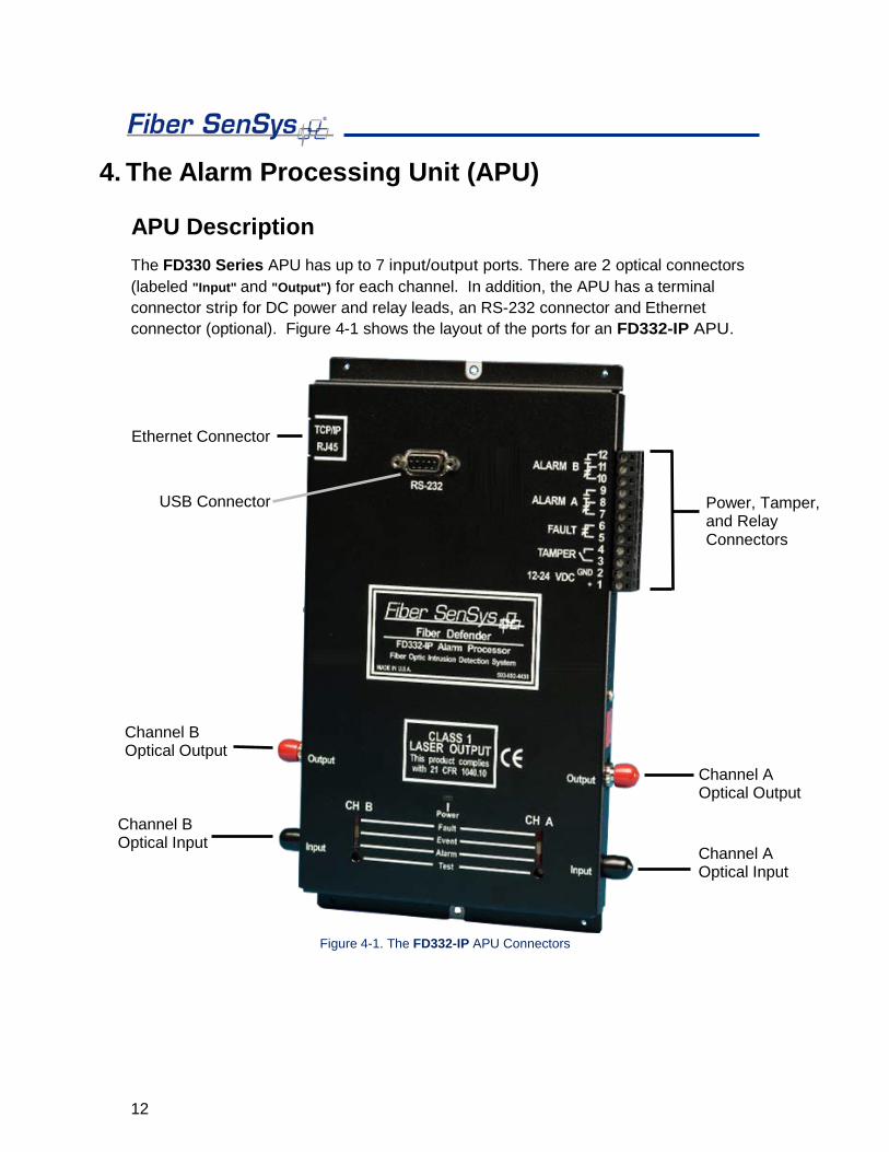
APU Description The FD330 Series APU has up to 7 input/output ports. There are 2 optical connectors (labeled "Input" and "Output") for each channel. In addition, the APU has a terminal connector strip for DC power and relay leads, an RS-232 connector and Ethernet connector (optional). Figure 4-1 shows the layout of the ports for an FD332-IP APU.
Figure 4-1. The FD332-IP APU Connectors
USB Connector
Ethernet Connector
Channel A Optical Output
Channel A Optical Input
Channel B Optical Input
Channel B Optical Output
Power, Tamper, and Relay Connectors
13
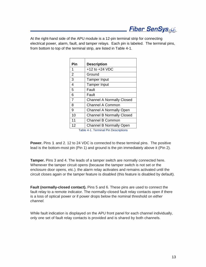
At the right-hand side of the APU module is a 12-pin terminal strip for connecting electrical power, alarm, fault, and tamper relays. Each pin is labeled. The terminal pins, from bottom to top of the terminal strip, are listed in Table 4-1.
Pin Description 1 +12 to +24 VDC 2 Ground 3 Tamper Input 4 Tamper Input 5 Fault 6 Fault 7 Channel A Normally Closed 8 Channel A Common 9 Channel A Normally Open 10 Channel B Normally Closed 11 Channel B Common 12 Channel B Normally Open
Table 4-1. Terminal Pin Descriptions
Power. Pins 1 and 2. 12 to 24 VDC is connected to these terminal pins. The positive lead is the bottom-most pin (Pin 1) and ground is the pin immediately above it (Pin 2).
Tamper. Pins 3 and 4. The leads of a tamper switch are normally connected here. Whenever the tamper circuit opens (because the tamper switch is not set or the enclosure door opens, etc.), the alarm relay activates and remains activated until the circuit closes again or the tamper feature is disabled (this feature is disabled by default).
Fault (normally-closed contact). Pins 5 and 6. These pins are used to connect the fault relay to a remote indicator. The normally-closed fault relay contacts open if there is a loss of optical power or if power drops below the nominal threshold on either channel.
While fault indication is displayed on the APU front panel for each channel individually, only one set of fault relay contacts is provided and is shared by both channels.
14
Channel A Alarm (normally-closed contact). Pins 7 and 8. When the APU determines that an alarm condition in channel A is met, the contact opens. In an unpowered state, this contact is open.
Channel A Alarm (normally-open contact). Pins 8 and 9. When the APU determines that an alarm condition in channel A is met, the contact closes. In an unpowered state, this contact is closed.
Channel B Alarm (normally-closed contact). Pins 10 and 11. When the APU determines that an alarm condition in channel B is met, the contact opens. In an unpowered state, this contact is open.
Channel B Alarm (normally-open contact). Pins 11 and 12. When the APU determines that an alarm condition in channel B is met, the contact closes. In an unpowered state, this contact is closed.
WARNING! DO NOT APPLY AC VOLTAGE TO THESE PINS. THE ALARM RELAY CONTACTS ARE RATED FOR DC VOLTAGE ONLY (100mA at 24 VDC).
LED indicators. LED indicators for each channel are found on the front panel of the module.
• "Fault" indicates a loss or significant degradation of returning optical power.
• "Event" indicates a disturbance or event has been detected in the sensor cable.
• "Alarm" indicates an alarm condition has occurred.
• "Power'' indicates the module is plugged in and receiving power.
Pressing the Test button (located below the LED indicators) causes the ALARM and FAULT LEDs to light up and the corresponding relay contacts to change state.
On the upper left-hand side of IP enabled APUs, there is an RJ45-style connector for TCP/IP Ethernet communication with a security head-end or other annunciator/monitoring equipment.
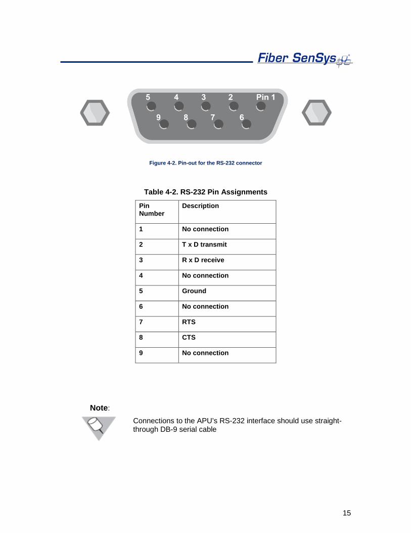
The front panel of the APU has an RS-232 connector for connecting to a PC during calibration. The pin-out for the RS-232 connector is shown in figure 4-2 and table 4-2.
15
Figure 4-2. Pin-out for the RS-232 connector
Table 4-2. RS-232 Pin Assignments
Pin Number
Description
1 No connection
2 T x D transmit
3 R x D receive
4 No connection
5 Ground
6 No connection
7 RTS
8 CTS
9 No connection
Note:
Connections to the APU’s RS-232 interface should use straight-through DB-9 serial cable
16
5. SpectraView
Terminal emulation software or SpectraView tuning software is required to adjust the tuning parameters of the APU. They run on a PC that is connected to the APU via the RS-232 port located on the front of the APU. Any terminal emulation software will work to change APU parameters, but SpectraView is recommended for precision tuning.
SpectraView is a Windows-based software module that allows for the tuning of the system so that it has maximum sensitivity when detecting intrusions with maximum rejection for nuisance alarms. SpectraView also allows the user to monitor system performance, as well as record and analyze sensor data.
For instructions on how to change settings using terminal emulator software, refer to Appendix B within this manual.
Using SpectraView With power off to the APU, connect one end of an RS-232 cable to the APU, and the other end to the PC from which you will be launching SpectraView; then turn on power to the APU.
Launch the SpectraView software by clicking on the icon pictured below or by navigating to “All Programs | Fiber SenSys | SpectraView”:
Figure 5-1. SpectraView Icon
Upon launching the program, click the tab in the top left labeled “Serial Port” and click on the appropriate port from the list of available ports. Then click “Connect to COM Port.”

17
Figure 5-2. The Serial Port pop-up window
APU Parameter Editor Mode From the tab on the left labeled “Modes” select “Parameter Editor.” The parameter editor mode (see figure below) is where parameters are read, defined, and written to the APU.

18
Figure 5-3. The SpectraView Parameter Editor screen
Press the Receive button (upper right-hand corner of the screen) to read the current tuning parameters from the APU. SpectraView queries the APU, reads in the processor information, and displays it:
19
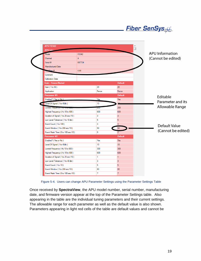
Figure 5-4. Users can change APU Parameter Settings using the Parameter Settings Table
Once received by SpectraView, the APU model number, serial number, manufacturing date, and firmware version appear at the top of the Parameter Settings table. Also appearing in the table are the individual tuning parameters and their current settings. The allowable range for each parameter as well as the default value is also shown. Parameters appearing in light red cells of the table are default values and cannot be
20
edited. Appearing also in the table are rows for entering comments, and the date of calibration.
To edit or change a parameter setting:
1. Click on the desired parameter (only parameters appearing in white table cells can be edited). The parameter’s row is highlighted in yellow indicating it is ready for editing.
2. Change the parameter setting to the desired value. Numerical values can be entered using the number keys or incremented/decremented from the current value using the + or – keys. Numerical values must also be kept within the allowable range or the software will reject the new value and prompt the user to enter a value within range.
3. Once the parameters have been edited, the new settings can be saved to the APU by pressing the Send button.
For detailed information about these tuning parameters, see the Fiber SenSys application note on tuning parameters titled: AN-SM-008 Setting the Tuning Parameters.
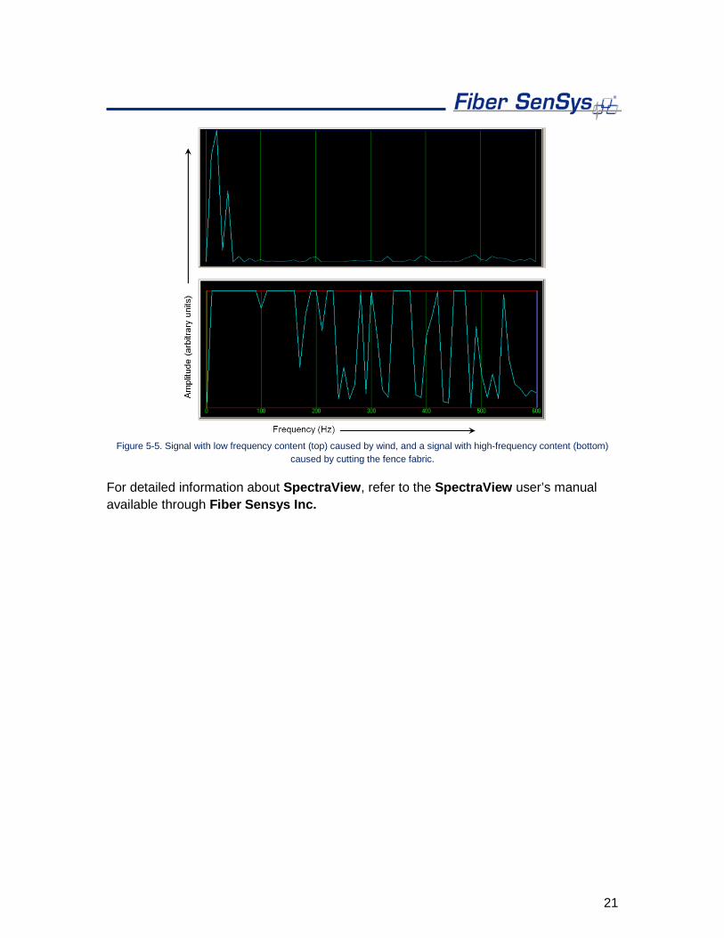
Realtime Mode As a tuning aid, SpectraView provides a powerful tool to help visualize the live frequency content of different sensor signals called Real Time (see figure 5-5). To use this function, from the tab on the left labeled “Modes” select “Real Time.”
21
Figure 5-5. Signal with low frequency content (top) caused by wind, and a signal with high-frequency content (bottom)
caused by cutting the fence fabric.
For detailed information about SpectraView, refer to the SpectraView user’s manual available through Fiber Sensys Inc.

22
6. Integrating the APU into the Security System
The IP enabled FD330 Series APU is designed to be installed into a local-area network (LAN) and connected to a security head-end or other annunciator/monitoring equipment.
The FD331-IP and FD332-IP communicates via XML (extensible markup language) sending status messages to the network such as alarm, tamper, and fault conditions. It can also receive device-configuration commands in XML format.
Processes involved in integrating the APU into a security system are described in detail in the networking application note, AN-SM-009 APU Networking.

23
7. Testing and Certification
System tuning is necessary when installing new systems, replacing APUs, or after performing any system maintenance that involves changes to the cable assembly. Anytime the system is tuned, it should be re-tested to verify that it meets all requirements for probability of detection (PD) and rejection of nuisance alarms. Basic tests include:
Tamper test
If the tamper input on the FD330 Series APU is enabled, the connection should be tested by going to the tamper-protected enclosure, opening it, and verifying that the head-end records a tamper alarm.
Fault test
The fault test verifies that a loss of optical power to a zone results in a cable fault indication for that zone on the APU. To conduct this test, disconnect the optical fiber for zone 1 and verify that the fault LED for zone 1 is illuminated (this LED is located on the front of the APU). Reconnect the fiber from zone 1 and verify that the fault LED light goes off. Repeat this process for the other zones.
Probability of detection (PD)
PD performance testing involves reviewing the sorts of threats that need to be detected, simulating those threats, and measuring the probability with which the system detects the expected method of intrusion. To obtain statistically significant samples, perform each threat simulation a minimum of 20 times at various locations in each zone.
For example, to determine the PD for an intruder attempting to climb the fence, have a volunteer climb nearly to the top of the fence, preferably bringing his or her beltline level with the top of the fence fabric, and then dismount in a controlled and steady manner. Perform the simulated intrusion at least 20 times while keeping track of the number of times the system triggers an alarm (count only one alarm per simulated intrusion).
Verify that the system triggers an alarm, as intended, with the required probability of detection. If the PD is too low, tune the system to be more sensitive. Repeat this procedure for each installed zone on the secured perimeter.

24
8. Maintenance
Maintenance consists of routine inspections and periodic testing to verify the performance of the tamper and fault alarms, as well as the probability of detection for simulated intrusions.
Visually inspect the FD330 Series APU and sensor deployment at least every 90 days:
1. Ensure the Power LED is illuminated and all alarm and fault LED indicators are normal.
2. Check the optical connectors at the sides of the APU, making sure they are not pinched or otherwise compromised.
On a periodic basis (once every 180 days at a minimum), perform the tests described in section 7:
• Tamper (if used).
• Fault.
• Probability of detection.
• Relay function (if used).
There are no user-serviceable parts in the FD330 Series APU. In case of an APU failure, corrective maintenance involves replacing the APU. If you replace the APU, you must perform a complete system configuration and recalibration.
To replace the APU, follow these steps:
1. Ensure all current APU calibration parameters, as well as the system configuration data, have been saved to a PC file using SpectraView.
2. Disconnect power to the APU and disconnect the optical fibers. Disconnect the Ethernet connection from the TCP/IP port.
3. Remove the APU and replace it with a new unit.
4. Clean all the optical connectors per the procedures described in the fiber optics application note: AN-SM-007 Fiber Optics.
25
5. Connect power to the new APU and repeat the processes described in the chapters in this manual on tuning, integration, and testing.
For troubleshooting assistance, contact Fiber SenSys Technical Support Service: telephone, 1-503-726-4455; email, [email protected]; or go to the Fiber SenSys website, www.fibersensys.com.

26
Appendix A. Product Specifications System Type Alarm processor for perimeter security
Number of Zones Two fully independent zones
Multimode Sensing Fiber
• Uniform sensitivity over the entire length • Sensing fiber length: ≤ 5 km (3.1 miles) • Maximum pull tensile Strength: 27kg (60 lb) • Minimum bend radius: 5 cm (2 in) • Passive, inert, intrinsically safe • Immune to EMI and corrosion
APU Power Requirements
• 12-24 VDC input • 3 watts @ 12 VDC, 25˚ C
Communications
• RS-232 port for tuning • Optional TCP/IP port for alarm output and XML
communication
Fault and Alarm Relays
• Individual dry contact alarm relays for each zone – normally open or normally closed (NO / NC)
• Dry contact alarm relay for fault – Normally Closed (NC) • 28 to 14 AWG • 100 mA, 24 VDC non-inductive • Dry Contact Resistance 11 Ω typical, 17 Ω max
Front-Panel Display LED indicators for fault and alarm conditions for each zone
Environmental Temperature: -40˚ C to 70˚ C (-40˚ F to 158˚ F) Humidity: 0 to 95% non-condensing
Dimensions Height = 4.5 cm (1.77 inch) Width = 42.5 cm (16.75 inch) Depth = 40.6 cm (16 inch)
Standards and Certifications
• RoHS • CE • FCC Part 15 Class B

27
Appendix B. FD330 Series Menu Structure This appendix provides details for all programmable FD330 Series system tuning parameters. Each channel on the FD330 Series APU is tuned independent of the other. Therefore, most parameters discussed in this appendix are duplicated in both channels.
Connect the PC to the APU via serial cable. Launch the terminal emulation software or SpectraView, and establish communication between the two instruments. The following properties must be set to communicate using terminal emulation software:
Bits per Second: 9600 Data bits: 8 Parity: None Stop bits: 1 Flow control: Hardware
Upon establishing communication with the APU, either through SpectraView in “terminal” mode or any other terminal emulation software, the system differentiates which channel is selected at the password prompt:
"CHa Unit is LOCKED, Enter Password"
--or--
"CHb Unit is LOCKED, Enter Password"
At the password prompt, type either "CHA" for Channel A or "CHB" for Channel B to switch from one channel to another. In each channel, there are 6 user-definable "passwords" that provide the user with access to related APU parameters or submenus. For instance, the "GAIN" password provides users with access to the gain setting. After entering the password, "GAIN," users can make adjustments to the setting as desired. The defaults for these 6 parameter passwords are:
• GAIN • SETUP • HIST • STATUS • VERSION • CHA/CHB

28
Each password, and its associated parameters, is explained in detail in the following pages. Factory default settings for fence line settings were chosen based upon the performance of an FD330 Series APU used in tandem with a seven foot chain link fence having a three-strand barbed wire outrigger.
NOTE: Press the Enter key at any time to exit from any menu, submenu or
parameter in the terminal emulation software.
GAIN
A password of "GAIN" allows access to the gain setting of the APU. The default setting is 20 and the range is 1 to 50. Gain raises and lowers the overall signal level. Raising the gain increases the signal level, making it easier for the signal to exceed the level threshold that defines events. Thus, increasing Gain increases the overall system sensitivity. Because Gain boosts the sensor signal, a higher Gain value increases the likelihood of detecting an intruder, but also increases the likelihood of nuisance alarms. Note, however, that the change in signal level is not displayed in RealTime mode.
SETUP
Access this menu using the "SETUP" password. There are 4 submenus available.
• Wind [1]
• Comment [2]
• Date [3]
• Calibrate [4]
These submenus are accessed by entering their corresponding submenu numbers ("1" for the Wind submenu, "2" for the Comment submenu, etc.).
29
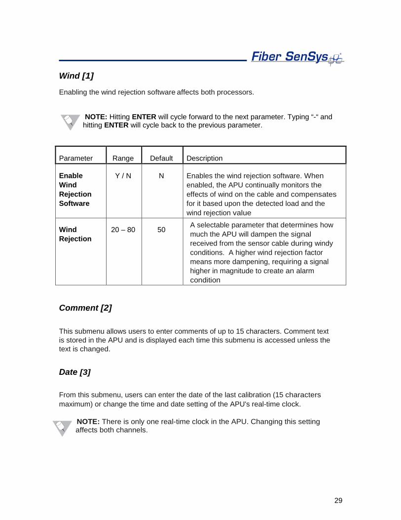
Wind [1]
Enabling the wind rejection software affects both processors.
NOTE: Hitting ENTER will cycle forward to the next parameter. Typing “-“ and hitting ENTER will cycle back to the previous parameter.
Parameter Range Default Description
Enable Wind Rejection Software
Y / N N Enables the wind rejection software. When enabled, the APU continually monitors the effects of wind on the cable and compensates for it based upon the detected load and the wind rejection value
Wind Rejection
20 – 80 50 A selectable parameter that determines how much the APU will dampen the signal received from the sensor cable during windy conditions. A higher wind rejection factor means more dampening, requiring a signal higher in magnitude to create an alarm condition
Comment [2]
This submenu allows users to enter comments of up to 15 characters. Comment text is stored in the APU and is displayed each time this submenu is accessed unless the text is changed.
Date [3]
From this submenu, users can enter the date of the last calibration (15 characters maximum) or change the time and date setting of the APU's real-time clock.
NOTE: There is only one real-time clock in the APU. Changing this setting affects both channels.
30
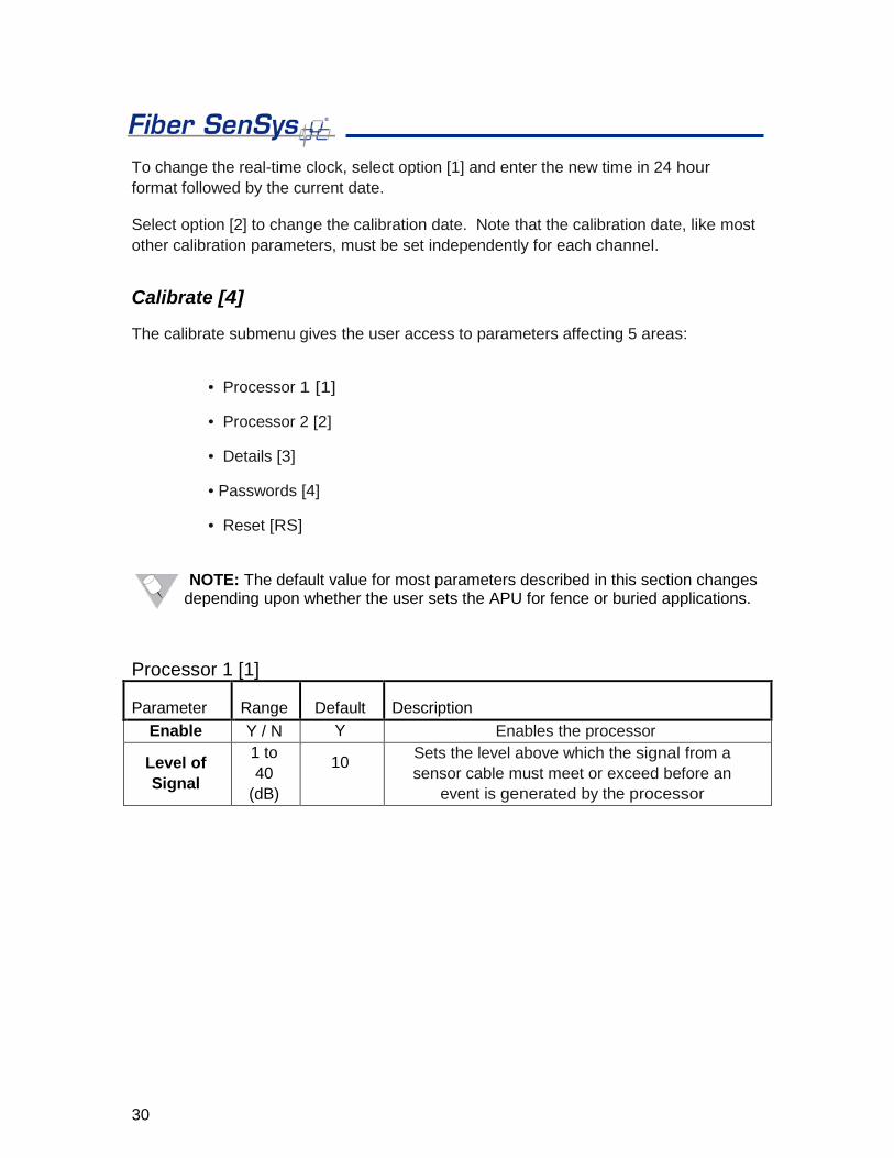
To change the real-time clock, select option [1] and enter the new time in 24 hour format followed by the current date.
Select option [2] to change the calibration date. Note that the calibration date, like most other calibration parameters, must be set independently for each channel.
Calibrate [4]
The calibrate submenu gives the user access to parameters affecting 5 areas:
• Processor 1 [1]
• Processor 2 [2]
• Details [3]
• Passwords [4]
• Reset [RS]
NOTE: The default value for most parameters described in this section changes depending upon whether the user sets the APU for fence or buried applications.
Processor 1 [1]
Parameter Range Default Description Enable Y / N Y Enables the processor
Level of Signal
1 to 40
(dB)
10
Sets the level above which the signal from a sensor cable must meet or exceed before an
event is generated by the processor
31
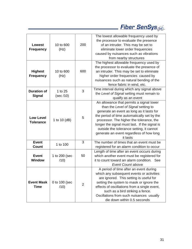
Lowest Frequency
10 to 600 (Hz)
200
The lowest allowable frequency used by the processor to evaluate the presence
of an intruder. This may be set to eliminate lower order frequencies
caused by nuisances such as vibrations from nearby structures
Highest Frequency
10 to 600 (Hz)
600
The highest allowable frequency used by the processor to evaluate the presence of an intruder. This may be set to eliminate
higher order frequencies caused by nuisances such as natural bending of the
fence fabric in wind, etc.
Duration of Signal
1 to 25 (sec /10)
3
Time interval during which any signal above the Level of Signal setting must remain to
qualify as an event
Low Level Tolerance 1 to 10 (dB)
5
An allowance that permits a signal lower than the Level of Signal setting to
generate an event as long as it lasts for the period of time automatically set by the processor. The higher the tolerance, the
longer the signal must last. If the signal is outside the tolerance setting, it cannot
generate an event regardless of how long it lasts
Event Count 1 to 100
3
The number of times that an event must be registered for an alarm condition to occur
Event Window
1 to 200 (sec /10)
50
Length of time after an event occurs during which another event must be registered for it to count toward an alarm condition. See
Event Count above
Event Mask Time
0 to 100 (sec /10) 2
A period of time after an event during which any subsequent events or activities
are ignored. This setting is useful for setting the system to mask or ignore the effects of oscillations from a single event,
such as a bird striking a fence. Oscillations from such nuisances usually
die down within 0.5 seconds
32
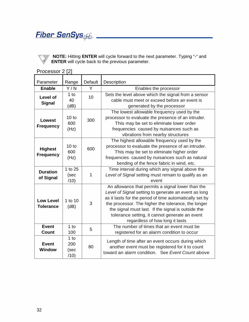
NOTE: Hitting ENTER will cycle forward to the next parameter. Typing “-“ and ENTER will cycle back to the previous parameter.
Processor 2 [2]
Parameter Range Default Description Enable Y / N Y Enables the processor
Level of Signal
1 to 40
(dB)
10
Sets the level above which the signal from a sensor cable must meet or exceed before an event is
generated by the processor
Lowest Frequency
10 to 600 (Hz)
300
The lowest allowable frequency used by the processor to evaluate the presence of an intruder.
This may be set to eliminate lower order frequencies caused by nuisances such as
vibrations from nearby structures
Highest Frequency
10 to 600 (Hz)
600
The highest allowable frequency used by the processor to evaluate the presence of an intruder.
This may be set to eliminate higher order frequencies caused by nuisances such as natural
bending of the fence fabric in wind, etc.
Duration of Signal
1 to 25 (sec /10)
1 Time interval during which any signal above the
Level of Signal setting must remain to qualify as an event
Low Level Tolerance
1 to 10 (dB) 3
An allowance that permits a signal lower than the Level of Signal setting to generate an event as long as it lasts for the period of time automatically set by the processor. The higher the tolerance, the longer
the signal must last. If the signal is outside the tolerance setting, it cannot generate an event
regardless of how long it lasts Event Count
1 to 100 5 The number of times that an event must be
registered for an alarm condition to occur
Event Window
1 to 200 (sec /10)
80 Length of time after an event occurs during which
another event must be registered for it to count toward an alarm condition. See Event Count above

33
Event Mask Time
0 to 100 (sec /10)
7
A period of time after an event during which any subsequent events or activities are ignored. This setting is useful for setting the system to mask or
ignore the effects of oscillations from a single event, such as a bird striking a fence. Oscillations from such nuisances usually die down within 0.5
seconds
Details [3]
Parameter Range Default Description (Fence/Buried)
Sensor on Fence
Y / N Y Configures the APU for fence or buried
applications. A “Y” value sets the system for fence operation
Alarm Relay Time
1 to 10 (sec) 1
Specifies the length of time, in seconds, during which the alarm relays remain in an alarmed state once an alarm condition is
set
Enable Tamper Switch
Y/N N
Enables or disables the tamper monitoring function. When enabled, the normally- closed condition of the tamper circuit is observed by the APU. If the circuit is
opened or not connected to the tamper switch in the enclosure, the tamper alarm will activate and remain activated until the
tamper circuit is closed or the tamper switch is disabled with this command. This
setting affects both APU channels simultaneously
XML Report Interval
1 to 600 (sec/10) 10 Adjusts the maximum frequency with which
XML reports are output
Enable User Controlled Relay Mode
Y/N N
Allows the user to directly operate the fault and alarm relays through XML. This disables relay stimulus upon an APU
alarm/fault
Sensitivity Factor 1 to 100 10
Scales the unprocessed signal from the protected zone. Typically used to increase
signal amplitude in SpectraView for improved signal visibility
34
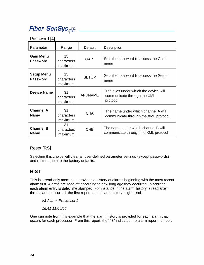
Password [4]
Parameter Range Default Description
Gain Menu Password
15 characters maximum
GAIN Sets the password to access the Gain menu
Setup Menu Password
15 characters maximum
SETUP Sets the password to access the Setup menu
Device Name 31 characters maximum
APUNAME The alias under which the device will communicate through the XML protocol
Channel A Name
31 characters maximum
CHA The name under which channel A will communicate through the XML protocol
Channel B Name
31 characters maximum
CHB The name under which channel B will communicate through the XML protocol
Reset [RS]
Selecting this choice will clear all user-defined parameter settings (except passwords) and restore them to the factory defaults.
HIST This is a read-only menu that provides a history of alarms beginning with the most recent alarm first. Alarms are read off according to how long ago they occurred. In addition, each alarm entry is date/time stamped. For instance, if the alarm history is read after three alarms occurred, the first report in the alarm history might read:
#3 Alarm, Processor 2
16:41 11/04/06
One can note from this example that the alarm history is provided for each alarm that occurs for each processor. From this report, the “#3” indicates the alarm report number,

35
“Processor 2” indicates the processor in which the alarm occurred and the date and time on the bottom line of the text indicates when the alarm was received. The “W=” parameter indicates the estimated wind speed at which the alarm occurred (determined by the internal wind rejection algorithms).
Up to 128 of the most recent alarm events will be stored in volatile APU memory. Each alarm event exceeding the allowable 128 will overwrite the oldest entry. If at any point you wish to exit this menu then enter “Q”.
STATUS
This is a read-only command that provides a real-time diagnostic of conditions such as system loss, laser current, power supply voltage (to the APU) and any present fault, event or alarm conditions. When this menu is chosen, for example, the display reads: Cha Loss: 1 Las(mA): 17.2 Pwr(V): 11.9 [Evnt1][Evnt2][Alarm][Fault]
“Evnt1” and “Evnt2” refer to event conditions at Processor 1 and Processor 2.
The laser current should never exceed 40 mA. Laser current readings in excess of 40 mA may indicate that the laser is damaged.
VERSION
This read-only menu gives the APU model number, serial number, firmware version, date of manufacture and the number of days the unit has been in operation.
Fiber Defender FD330 SeriesTM User Manual 36
Appendix C. Warranty information A. Fiber SenSys warrants the FD330 Series APU to be free from electrical and mechanical defects in materials and workmanship for a period of two years from the date of shipment. This warranty does not apply to defects in the product caused by abuse, misuse, accident, casualty, alteration, negligent use of current or voltages other than those specified by Fiber SenSys, application or installation not in accordance with published instruction manuals, or repair not authorized by Fiber SenSys. This warranty is made in lieu of any other warranty either expressed or implied.
B. All returns will be tested to verify customer claims of non-compliance with the warranty described herein. If non-compliance is verified and is not due to customer abuse or the other exceptions described previously, Fiber SenSys will, at its option, repair or replace the FD330 Series APU returned to it, freight prepaid. Contact Fiber SenSys and obtain an RMA number prior to returning a product. Fiber SenSys will pay for ground return freight charges only. The Customer must pay for any other return shipping options.
C. Fiber SenSys liability is limited to the repair or replacement of the product only, and not the costs of installation, removal, or damage to user’s property or other liabilities. If Fiber SenSys is unable to repair or replace a non-conforming product, it may offer a refund of the amount paid to Fiber SenSys for such product in full satisfaction of its warranty obligation. Maximum liability to Fiber SenSys is the cost of the product.
Fiber Defender FD330 SeriesTM User Guide 37
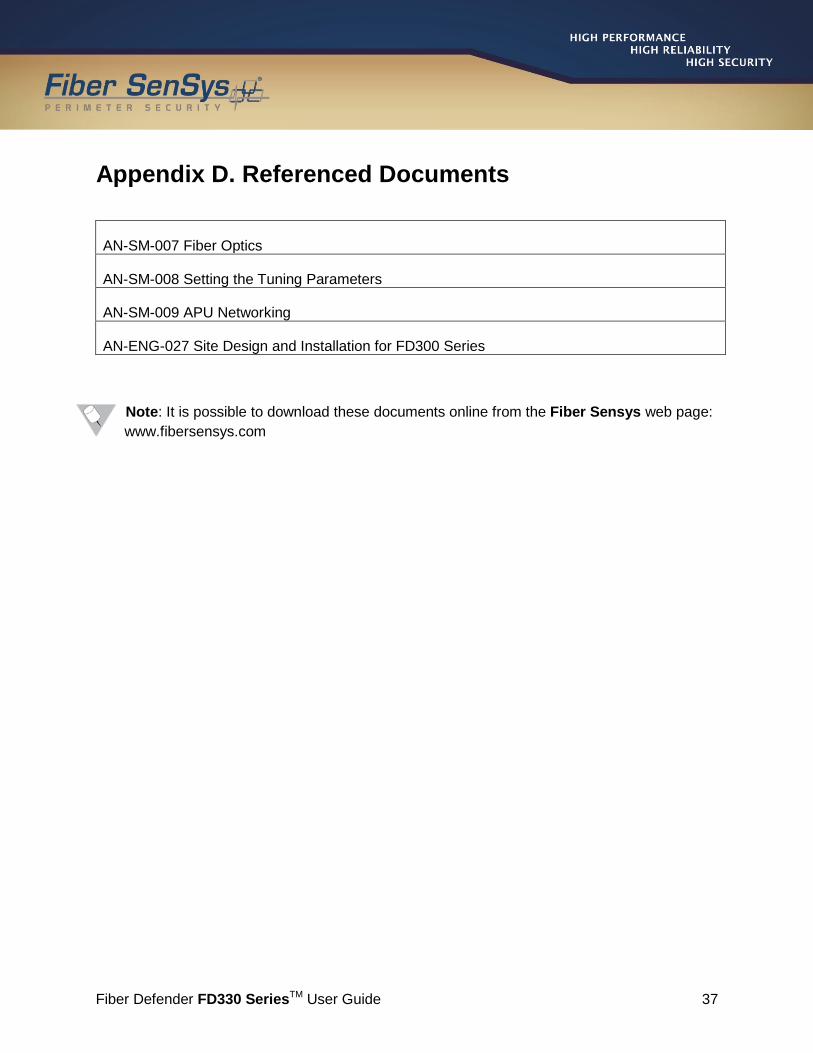
Appendix D. Referenced Documents
AN-SM-007 Fiber Optics
AN-SM-008 Setting the Tuning Parameters
AN-SM-009 APU Networking
AN-ENG-027 Site Design and Installation for FD300 Series
Note: It is possible to download these documents online from the Fiber Sensys web page: www.fibersensys.com