
FERRANTI -...
7
Transcript of FERRANTI -...

FERRANTI
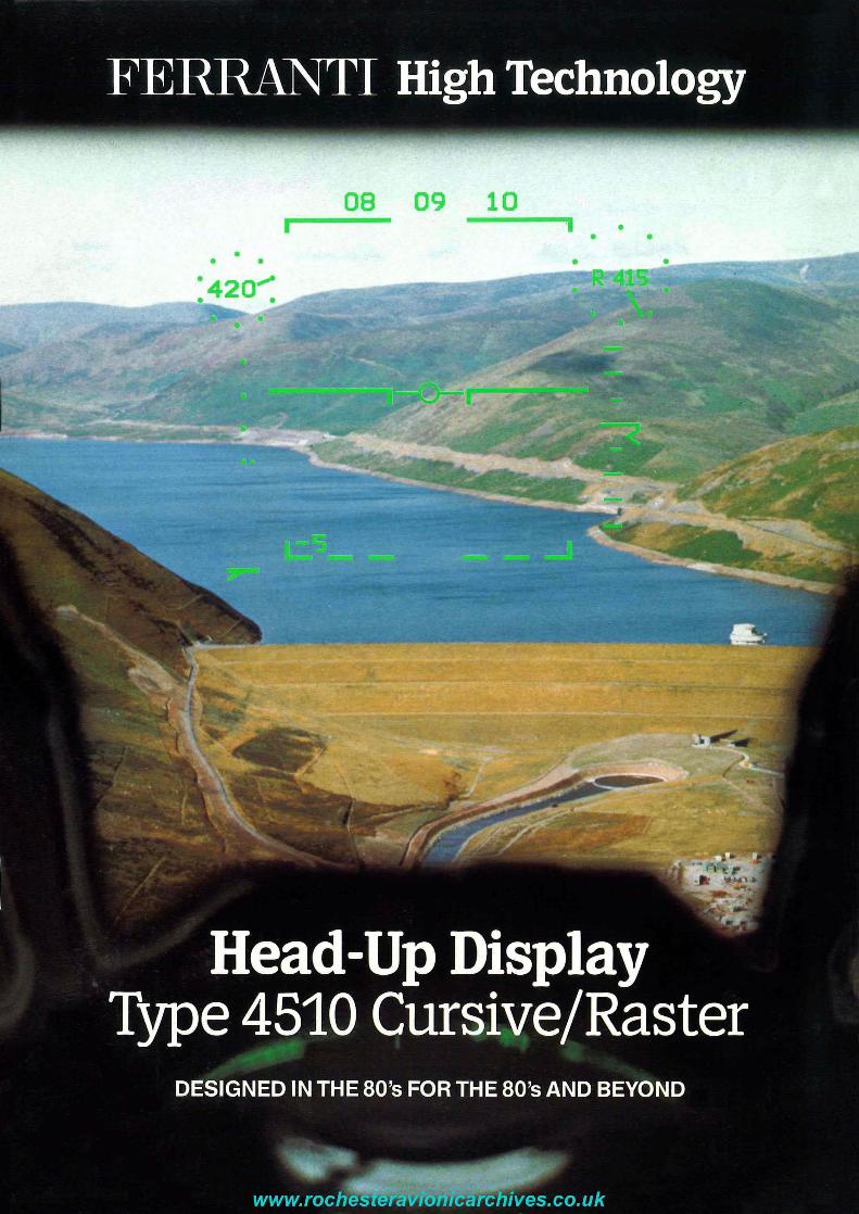
The Ferranti Type 4510 Cursive/Raster Head-Up Display
-0- Designed and built in the 80's for the 80's and beyond.
-0- Designed to fit in the minimum of space with the minimum of engineering effort.
-0- Designed to control the entire weapon system bydayand by night
The Ferranti Type 4510 Head Up Display a derivative of the Type 4500, is based on proven hardware modules from navigation, weapon aiming and display systems currently in use worldwide.
High reliability is engineered into the Head Up Display and is a result of extensive proving of the various modules during lengthy production runs.
The symbology is scaled 1:1 with the outside world, and the formats can readily be changed at first line servicing, without the unit being
removed from the aircraft. A monochrome or colour video
camera is fitted and is powered by the Head
Up Display without external wiring.
Advanced Technical Design Features
The Ferranti Type 4510 Head Up Display system consists of a Pilot's Display Unit, a weapon aiming computer, an up front control panel, and a video camera.
Modular in design, the system will fit in the smallest of modern Strike and Trainer aircraft. The Pilot's Display Unit contains the CRT, the EHT power supply, the deflection amplifiers, the video ci rcu its and the system BITE modules. Positioning of the EHT unit close to the CRT gives greatly enhanced performance and reliability.
Although the Head Up Display is physically small a 4.5/1 exit lens and dual combiner glasses give a total circular field of view of 25°.
The use of burn resistant phosphor, P53, dramatically increases the brightness over previous displays, allowing clear reading of the symbols even when pointing directly into the sun. This may be critical in air combat. The extra brightness also allows display of raster generated symbology and sensor information to be used in some daylight conditions.
Based on programmable software which can facilitate changes of symbology and moding at squadron level, the Head Up Display system has the facility of uploading or downloading developed software via a digital link.
The Weapon Aiming Computer is installed with a waveform generator, electronics unit and system interface, in a 3/4 ATR short unit which can also act as BusController.
and allows straight video recording from the interface unit should a camera not be fitted.
To meet customers navigation requirements interfaces can be made with all existing en route and landing aids.
The ability to mix raster symbology with FUR or LLTV provides the pilot with a complete symbol suite even when using a night sensor,
TYPICAL INTERFACE UNIT CONFIGURATION
DUAL PROCESSOR

FERRANrI
Operational Procedures Up Front Control Panel
: e 0~ ~ ~ l! ~ ~ I;"
~) ~ (£ r W4 L'_ (:E ~ HT !oo,BAA "-----
~ l:: ~~~. ~- ~ ~ ~ ,leK
~ ~ DST le/. (~ l~_ ~~ 6
In order to minimise pilot workload, the up front control panel
has been designed to carry out all system initiation procedures, all mode selections, and every
dedicated Head Up Display switching which may be required during a sortie.
- _I!III The panel, which is integrally lit, is night vision goggle (NVG compatible, and is fitted with carefu lly designed fences round sections of buttons to prevent incorrect selection during combat conditions.
Read/alter MB setting
DTA Call up
.----- --------1 A1G g~~:~~7ru DATA MENU OPllONS BAR ~~f~c~d
baro hI Although specific requirements THT Set timel
must be left to the individual ~n~~r~atio n customer the following list gives AlA ~i~lect ai rl
an example of a current fit WPT Set waypoint
1 pp - Display or insert OFS Set offset CH/DST Change
present position destinatio n
2 H G CIA Selectcur-
, . Digits ENT
Keyboard enter CLR
Keyboard
readoutof Mach No.
ariAS RAD/ BAR readout of radar or
barometri c height W / LCK
symbology centred on
Velocity Vector or locked
During normal flight, the data working line gives the pi lot navigation information about his next selected destination, unless he is using the faci lity to check or change some current store. D - Display or insert sive orras-
current heading ~ _ _ te_rd_lsp_la_y --'--c----:---'------' ---------------,
3 SWP - Display or insert required waypoint 4 SWV - Insert reversionary wind velocity 5 WPN - Check status of current weapon load 611M - Set GMT. and system time 7 VlUHF - Set or select VIUHF frequency 8 TAC - Set or select Tacan Beacon
Selection of DTA brings up a Data Menu on the Head Up Display from which the pilot can select the subject he requires.
Further selection brings the desired subject on to a data working line as a volatile store.
TOTAL SYSTEM BITE is initiated before flight by pressing the system warning light/button. Any module defect is reported on the data working line.
Related symbology is removed from the Head Up Display should its source become suspect during flight, or a fai lure oocur.
In addition, comparator circuits in the system report any disparity in outputs from various attitude or velocity sources by illuminating the system warning light.
By pressing the button, the pilot can identify the problem and alter his flight plan accordingly.
e
Operational Displays and Facilities
SYMBOLOGY AND MODING
The Ferranti Head Up Display is based on programmable software and the symbology and moding is thereby capable of being adapted to any particular aircraft or customer requirements.
It is designed to be adaptable at squadron level, which allows individual aircraft to be programmed for individual tasks if necessary . This is particularly useful where squadrons or training units have split responsibi lities.
0~ ~ Ll! ~ ~I ~ (£ HT ~l ~ ~ l:: ~. L ~ ~ ~ ~ DST ~/~ (~ l~ ~
RADIO AND FACILITY SELECllON
~ ~ ,-BAR
~ , leK
6
To customer requirement, the Up Front Control Panel can be used to select required V/UHF channels and for selection and identification of en route navigation aids.
\:::'.
Typical Display Formats available
GROUND ENGINEERING MODES
The all round capability of the software allows engineering personnel to access the computer, by special code, through the Up Front Control Panel. By this means, system moding changes, serviceability checks, fault detection and harmonisation can be carried out without removing the unit from the aircraft.
Windscreen distortion corrections are also made through the Up Front Control Panel, as are specific harmonisation changes to suit individual external sensors.

Raster: An all round capability
08 i
• • • ·420 ..... • •
• •
The Ferranti Head Up Display is a Raster compatible system which can be switched from conventional cursive symbology writing mode, to flexible, sensor compatible Raster, by a button on the Up Front Control Panel.
09 i • • •
In Raster Mode the Head Up Display is capable of producing a Raster Video Display combined with a full suite of navigation or weapon aiming symbology.
THE TYPE 4510 CRT AND OPTICS ARE COMPATIBLE WITH ALL TYPES OF NIGHT VISION GOGGLES (N.V.Gel
Although the main application for Raster capabi lity is visual flying in darkness using a FUR or LLlV sensor, the high brightness phosphor enables radar information to be shown in lower light conditions of daylight.
In all cases, the pilot can select Raster symbology only, sensor video only, or a correctly harmonised mix of both as required.
All switching is on the Up Front Control Panel.
Raster: A 24 hour vision
The relative ease of identifying a target on such a day depends on good navigation and reasonable visibility.
No problems here for a competent pilot and a good navigation system .
DB 09 10 r-- ~
The same situation later in the day may well look like this on conventional Head Up Displays. This time the pilot is at risk and the navigation system impotent.
The addition of the Raster capable Head Up Display and a suitable sensor, literally turns night into day and provides the pilot with a complete new dimension to his capability.
THIS MUST BE A REQUIREMENT FOR THE NEXT DECADE

System Compatibility
The Head Up Display has been designed to interface with any existing analogue or digital system.
The Pilot's Display Unit can be a stand alone unit capable of integrating with any external navigation system.
The PDU is normally fitted with a Ferranti monochrome or colour video camera, integrally powered, but is also compatible with any existing video recording system.
The Head Up Display system normally marketed by Ferranti consists of the Pilot's Display Unit and a weapon aiming computer.
Installed in a 3/4 ATR short unit, which also contains the waveform generator, the mission computer, the electronics unit and the total system interface unit, the weapon aiming computer can form the basis of any modern attack system.
By adding a RN 2000 Type of inertial sensor to the Pilot's Display Unit and weapon aiming computer, the operator is assured of the most accurate of total systems now in production worldwide.
To complete a system entirely suitable for light Strike and Training tasks, the Attitude and Heading Navigation System (AHNS) is added to the Pilot's Display Unit and the weapon aiming computer.
Coupled with quick reaction and self alignment, this system provides the full range of Air/Air and Air/Ground modes and is completely compatible with modern missiles.
This offers the quick reaction and minimum alignment task suitable for training aircraft and, when augmented by Doppler, provides navigation and weapon aiming results only improved by using a full inertial system.
A laser can be integrated as required as can any existing radar fit.

Cockpit Installations
By compact engineering and use of the latest miniaturisation techniques, Ferranti have achieved the smallest possible unit size for the Type 4510.
This has been achieved while still retaining a 25° total field of view.
The Pilot's Display Unit can be mounted on existing gunsight fi xtures without
engineering effort, or it can be integrated with the previous gunsight electronic unit as in the F-5E This again makes for a minimum cost fit and no harmonization problems.
Installation in the Harrier was carried out without cockpit change, the unit picking up on
the existing mounts. An extensive
flight programme demonstrated the
excellent instantaneous field of view and proved
the concept of the up front control panel.
The above installations are used as examples of the versatility of the Ferranti Head Up Display using the common optical unit and variable combiner glass angle.
effort and to restrict cockpit changes when fitting the Head Up Display.
The aim has been to minimise engineering
Installation details have been completed on an extensive variety of aircraft worldwide from Turbo-Trainers to Fighter/Bombers.
FERRANTI FD 4510 FITS
Technical ~pecifications
16-800
DIMENSIONS PDU As above. WAC The weapon-aiming computer is an Arinc standard 3f4 ATR (short).
INTERFACING The HUDIWAC can interface with air data systems or inertial navigation systems, including those using MILSTD-1553B data bus if required.
CONTROL The PDU has an integral Up- front Controller which provides all the functions normally carried out by an inertial navigation control and display unit.
COOLING The PDU does not require cooling air. The WAC requires a conditioned air flow of11 6/MIN at 0·8 INCH WIG.
WEIGHT PDU12kg WAC14kg
TOTAL POWER 115V 400 Hz 3 phase 350VA, 28V DC 28VA or 28V DC 350 Watts
MTBF PDU 2053 hrs WAC2054 hrs
LENS The PDU has a 4.5 inch (114mm) objective lens
FIELD OF VIEW Total field of view: 25° circular
o It)
N
(') ,....

Ferranti is a world leader in technologically advanced, highly reliable military systems.
Ferranti head-up weapon-aiming sights are in almost every type of light strike aircraft, and thousands are in use throughout the world.
-<r- Ferranti head-down projected map and electronic displays are in the Harrier, Jaguar, Tornado, and F18 Hornet.
-<r- Ferranti inertial systems are in the Harrier, Phantom, Jaguar, Tornado, Sea Harrier, HS748, Nimrod and Mitsubishi F-1.
-0- Ferranti radars are in the Buccaneer, . Sea Harrier and Lynx helicopter with
major parts in production for Tornado.
-0- Ferranti lasers are in the Harrier, Jaguar, Tornado and Draken.
-0- Ferranti helmet-mounted pointing systems are in production for use with the Tracked Rapier.
-0- Ferranti mission planners and automatic test equipment are used by the RAF and the airforces of Germany · and Italy.
These systems, designed, developed,
produced and tested by one manufacturer (with most
of the components-from hybrid micro-circuits to gyroscopesalso being produced in-house) are backed world-wide by one
of Europe's largest military product support organis
ations. It is a capability few companies can
match.