Fentek Catalogue Sept02 Part 43995
14
FENDER DESIGN 66 67 FENDER DESIGN INSTALLATION & MAINTENANCE Installation of fenders should be considered early in the design process. Accessibility for maintenance may influence choice of materials, wear allowances and the protective coatings specified. The right fender choice may improve turnaround times and reduce downtime. Safety of personnel, structure and vessels must be considered at all stages – before, during and after commissioning. STRUCTURES Fenders impose loads onto the berthing structure. Many berths are being built in more exposed locations where fenders can play a crucial role in the overall construction costs. Local practice, materials and conditions may influence the choice of fender. T HE D ESIGN P ROCESS Many factors contribute to the design of a fender. SHIPS Ship design is constantly evolving – their shapes change and many vessel types are getting larger. Fenders must suit current ships as well as those expected to arrive in the foreseeable future. BERTHING Many factors will affect how vessels approach the berth, the corresponding kinetic energy and the load applied to the structure. Berthing mode may affect the choice of ship speed and the safety factor for abnormal conditions. Fender Design Fenders must reliably protect ships, structures and themselves – day after day for many years in severe environments with little or no maintenance. Good fender design demands an understanding of ship technology, civil construction methods, steel fabrications, materials, installation techniques and innumerable regulations and codes. This design guide should assist with many of the frequently asked questions which arise during fender design. It is best used in conjunction with suitable international Codes of Practice such as BS 1 , EAU 2 , PIANC 3 and ROM 4 as well as other sources of information. Fentek is always available and willing to assist with every aspect of fender design. References Code of Practice for Design of Fendering and Mooring Systems BS 6349 : Part 4 : 1994 (ISBN 0-580-22653-0) PIANC WG33 Guidelines for the Design of Fenders : 2002 (ISBN 2-87223-125-0) Recommendations of the Committee for Waterfront Structures EAU 1996 7th Edition (ISBN 3-433-01790-5) Report of the International Commission for Improving the Design of Fender Systems Supplement to Bulletin No.45 (1984) PIANC Maritime Works Recommendations – Actions in the Design of Maritime and Harbour Works ROM 0.2-90 (ISBN 84-7433-721-6) Ship Dimensions of Design Ship under Given Confidence Limits Technical Note of the Port and Harbour Research Institute, Ministry of Transport, Japan No. 911, Sept 1998 (ISSN 0454-4668)
-
Upload
gilang-nusantara-bening -
Category
Documents
-
view
241 -
download
0
Transcript of Fentek Catalogue Sept02 Part 43995

FEN
DER
DES
IGN
66 67
FEN
DER
DES
IGN
I N S T A L L A T I O N & M A I N T E N A N C EInstallation of fenders should be considered early in the design process. Accessibility formaintenance may influence choice of materials, wear allowances and the protective coatingsspecified. The right fender choice may improve turnaround times and reduce downtime. Safety of personnel, structure and vessels must be considered at all stages – before, duringand after commissioning.
S T R U C T U R E SFenders impose loads onto the berthing structure. Many berths are being built in more exposedlocations where fenders can play a crucial role in the overall construction costs. Localpractice, materials and conditions may influence the choice of fender.
TH E DE S I G N PR O C E S SMany factors contribute to the design of a fender.
S H I P SShip design is constantly evolving –their shapes change and many vesseltypes are getting larger. Fenders mustsuit current ships as well as thoseexpected to arrive in the foreseeablefuture.
B E R T H I N GMany factors will affect how vessels approach theberth, the corresponding kinetic energy and the loadapplied to the structure. Berthing mode may affect thechoice of ship speed and the safety factor forabnormal conditions.
Fender DesignFenders must reliably protect ships,structures and themselves – day afterday for many years in severeenvironments with little or nomaintenance. Good fender designdemands an understanding of shiptechnology, civil constructionmethods, steel fabrications, materials,installation techniques andinnumerable regulations and codes.This design guide should assist withmany of the frequently askedquestions which arise during fenderdesign. It is best used in conjunctionwith suitable international Codes ofPractice such as BS1, EAU2, PIANC3
and ROM4 as well as other sources ofinformation. Fentek is always availableand willing to assist with every aspectof fender design.
References
Code of Practice for Design of Fendering andMooring SystemsBS 6349 : Part 4 : 1994 (ISBN 0-580-22653-0)
PIANC WG33 Guidelines for the Design of Fenders :2002 (ISBN 2-87223-125-0)
Recommendations of the Committee for WaterfrontStructuresEAU 1996 7th Edition (ISBN 3-433-01790-5)
Report of the International Commission forImproving the Design of Fender SystemsSupplement to Bulletin No.45 (1984) PIANC
Maritime Works Recommendations – Actions in theDesign of Maritime and Harbour WorksROM 0.2-90 (ISBN 84-7433-721-6)
Ship Dimensions of Design Ship under GivenConfidence LimitsTechnical Note of the Port and Harbour ResearchInstitute, Ministry of Transport, JapanNo. 911, Sept 1998 (ISSN 0454-4668)

FU L L LI F E CO S T S
DE S I G N FL O W CH A R T
6968
FEN
DER
DES
IGN
FEN
DER
DES
IGN
All designers, contractors and operators want the best value for money from their investment in fenders. But when the initial purchase costof fenders is looked at in isolation, this does not give the full picture.Many structures are designed to last 50 years or more. Depending on the quality of the materials and design, fenders typically last 15-30 yearsso will need replacing at least once during the lifetime of the berth. Maintenance can also add substantial amounts to the overall costs.As the following examples show, a high quality and well designed fender system can yield savings from the very beginning.
Yes
No
No
No
No
No
No
Yes
Yes
Yes
Yes
Yes
Service Life, Loads etc.
Reaction Force Check Structure & Panels
Restraint Chain Sizes
Angular Performance
Tides, Hull Pressures etc.
Corrosion Protection etc.
Shear Forces
Berthing Angles
Panel Dimensions
Material Specifications
Select Fender and Panel Arrangement
Design Refinements
Type of Structure
Select Berthing Velocity, Calculate (Normal) Energy
Ship Data Berthing Mode Location & Environment
A B N O R M A L E N E R G Y
F I N A L F E N D E R D E S I G N
OK?
OK?
OK?
OK?
OK?
OK?
Safety Factor
‘ C H E A P E S T ’ F E N D E R D E S I G N L O W E S T ‘ F U L L L I F E C O S T ’ D E S I G N
45-5040-4535-4030-3525-3020-25
Cost
s
15-2010-155-100-5 45-5040-4535-4030-3525-3020-2515-2010-155-100-5
500
450
400
350
300
250
200
150
100
50
0
Time from installation
245
145
115100
260
290
390405
435
480
30
100
1530
100
1530 45
15
100
Construction savingsCost per periodCumulative costs
Cost
s
300
250
200
150
100
50
0
-50
-100
Time from installation
75
5
80
5
90
10
100
10
220
120
225
5
230
5
240
10
250
10
70
120
-50
Protrusions such as ‘cow catchers’ and other modifications can beprone to snagging on fenders. Large lead-in bevels or continuous fenderwall systems may be needed.
High speed catamarans and monohulls are often built of aluminium, socan only accept limited loads on their belting which may be high abovewaterline. Care is needed if accommodating high speed andconventional ferries on the same berth.
Gas Carriers, Tankers, Bulk Cargo and some other vessels require low hull contact pressures, achieved with large fender panels. Careshould be taken when designing for large tidal zones and with ‘tilting’fender systems.
High freeboard ships can be difficult to manoeuvre in strong winds soberthing speeds may be higher. Affected vessels include RoRo, CarCarriers and laden Container ships.
Stern doors are common on RoRo ships, often accompanied by variousdesigns of large stern belting. Side doors are fitted to most Car Carriers.These are usually recessed which can snag fenders, especially whennegotiating lock entrances.
Low freeboard vessels include barges, coastal tankers and somegeneral cargo ships. Ensure that the vessel cannot get caughtunderneath fenders at very low tides, when fully laden and in poorweather conditions.
Many RoRo and Cruise ships have a flying bridge. In large tidal zones, care should be taken to ensure these do not sit on top of thefender panel.
Most ferries, general cargo vessels and many container ships havebeltings. These can be intermittent and/or fitted at many levels. Beltingsin poor condition can cause fender damage. Belting sections vary –square or half-round are most common.
Bulbous bows are a feature of most modern ships. Care is needed whenfenders are widely spaced to ensure the bulbous bow cannot catchbehind fenders. Also ensure the bulbous bow cannot contact the frontrow of piles on the structure.
Large bow flares are common on Container and Cruise ships. The flareangle can reduce fender energy capacity. Larger fender projection maybe needed to keep vessels clear of the quay face and cranes. Care isalso needed when ships have stern flares.
SH I P FE AT U R E S & TA B L E S
Construction savingsCost per periodCumulative costs

7170
FEN
DER
DES
IGN
FEN
DER
DES
IGN
C O N T A I N E R S H I P S ( P A N A M A X )dwt MD LOA LBP B D F CB
(t) (t) (m) (m) (m) (m) (m) ---60,000 83,000 290 275 32.2 13.2 8.6 0.69355,000 75,500 278 264 32.2 12.8 8.1 0.67750,000 68,000 267 253 32.2 12.5 7.8 0.65145,000 61,000 255 242 32.2 12.2 7.5 0.62640,000 54,000 237 225 32.2 11.7 6.9 0.62235,000 47,500 222 211 32.2 11.1 6.3 0.61430,000 40,500 210 200 30.0 10.7 5.9 0.61525,000 33,500 195 185 28.5 10.1 5.3 0.61420,000 27,000 174 165 26.2 9.2 4.4 0.66215,000 20,000 152 144 23.7 8.5 3.8 0.67310,000 13,500 130 124 21.2 7.3 2.7 0.686
F R E I G H T R O - R Odwt MD LOA LBP B D F CB
(t) (t) (m) (m) (m) (m) (m) ---50,000 87,500 287 273 32.2 12.4 14.8 0.78345,000 81,000 275 261 32.2 12.0 14.2 0.78340,000 72,000 260 247 32.2 11.4 13.4 0.77535,000 63,000 245 233 32.2 10.8 12.6 0.75830,000 54,000 231 219 32.0 10.2 11.7 0.73725,000 45,000 216 205 31.0 9.6 10.9 0.71920,000 36,000 197 187 28.6 9.1 10.2 0.72215,000 27,500 177 168 26.2 8.4 9.2 0.72610,000 18,400 153 145 23.4 7.4 7.8 0.7155,000 9,500 121 115 19.3 6.0 5.8 0.696
G E N E R A L C A R G O S H I P Sdwt MD LOA LBP B D F CB
(t) (t) (m) (m) (m) (m) (m) ---40,000 54,500 209 199 30.0 12.5 4.5 0.71235,000 48,000 199 189 28.9 12.0 4.3 0.71430,000 41,000 188 179 27.7 11.3 4.1 0.71425,000 34,500 178 169 26.4 10.7 4.0 0.70520,000 28,000 166 158 24.8 10.0 3.8 0.69715,000 21,500 152 145 22.6 9.2 3.5 0.69610,000 14,500 133 127 19.8 8.0 3.2 0.7035,000 7,500 105 100 15.8 6.4 2.7 0.7242,500 4,000 85 80 13.0 5.0 2.3 0.750
C A R C A R R I E R Sdwt MD LOA LBP B D F CB
(t) (t) (m) (m) (m) (m) (m) ---30,000 48,000 210 193 32.2 11.7 13.8 0.64425,000 42,000 205 189 32.2 10.9 12.7 0.61820,000 35,500 198 182 32.2 10.0 11.4 0.59115,000 28,500 190 175 32.2 9.0 10.0 0.548
D E F I N I T I O N Sgross registered tonnage (grt)The gross internal volumetric capacity of the vessel measured in units of 2.83m3 (100ft3).deadweight tonnage (dwt)The total mass of cargo, stores, fuels, crew and reserves with which the vessel is laden when submergedto the summer loading line. Note that this is not an exact measure of the cargo load.lightweight tonnage (lwt)The total mass of the ship, excluding cargo. stores, fuels, crew and reserves. Note that lightweight tonnage+ deadweight tonnage = displacement tonnage.
MD = DisplacementLOA = Length OverallLBP = Length Between PerpendicularsB = BeamD = Laden DraftF = Laden Freeboard
U L C C & V L C C T A N K E R Sdwt MD LOA LBP B D F CB
(t) (t) (m) (m) (m) (m) (m) ---500,000 590,000 415 392 73.0 24.0 14.5 0.838400,000 475,000 380 358 68.0 23.0 13.5 0.828350,000 420,000 365 345 65.5 22.0 12.6 0.824300,000 365,000 350 330 63.0 21.0 11.7 0.816275,000 335,000 340 321 61.0 20.5 11.2 0.814250,000 305,000 330 312 59.0 19.9 10.7 0.812225,000 277,000 320 303 57.0 19.3 10.2 0.811200,000 246,000 310 294 55.0 18.5 9.5 0.802175,000 217,000 300 285 52.5 17.7 8.8 0.799150,000 186,000 285 270 49.5 16.9 8.2 0.803125,000 156,000 270 255 46.5 16.0 7.5 0.802100,000 125,000 250 236 43.0 15.1 6.8 0.79680,000 102,000 235 223 40.0 14.0 6.0 0.79770,000 90,000 225 213 38.0 13.5 5.6 0.80460,000 78,000 217 206 36.0 13.0 5.3 0.789
P R O D U C T A N D C H E M I C A L T A N K E R Sdwt MD LOA LBP B D F CB
(t) (t) (m) (m) (m) (m) (m) ---50,000 66,000 210 200 32.2 12.6 5.0 0.79340,000 54,000 200 190 30.0 11.8 4.5 0.78330,000 42,000 188 178 28.0 10.8 3.9 0.76120,000 29,000 174 165 24.5 9.8 3.2 0.71410,000 15,000 145 137 19.0 7.8 2.2 0.7215,000 8,000 110 104 15.0 7.0 1.8 0.7153,000 4,900 90 85 13.0 6.0 1.3 0.721
B U L K C A R R I E R Sdwt MD LOA LBP B D F CB
(t) (t) (m) (m) (m) (m) (m) ---400,000 464,000 375 356 62.5 24.0 9.5 0.848350,000 406,000 362 344 59.0 23.0 9.1 0.848300,000 350,000 350 333 56.0 21.8 8.6 0.840250,000 292,000 335 318 52.5 20.5 8.1 0.832200,000 236,000 315 300 48.5 19.0 7.4 0.833150,000 179,000 290 276 44.0 17.5 6.8 0.822125,000 150,000 275 262 41.5 16.5 6.4 0.816100,000 121,000 255 242 39.0 15.3 5.9 0.81780,000 98,000 240 228 36.5 14.0 5.4 0.82160,000 74,000 220 210 33.5 12.8 4.9 0.80240,000 50,000 195 185 29.0 11.5 4.4 0.79120,000 26,000 160 152 23.5 9.3 3.5 0.76310,000 13,000 130 124 18.0 7.5 2.9 0.758
C O N T A I N E R S H I P S ( P O S T P A N A M A X )dwt MD LOA LBP B D F CB
(t) (t) (m) (m) (m) (m) (m) ---70,000 100,000 280 266 41.8 13.8 9.2 0.63665,000 92,000 274 260 41.2 13.5 8.9 0.62160,000 84,000 268 255 39.8 13.2 8.6 0.61255,000 76,500 261 248 38.3 12.8 8.1 0.614

7372
FEN
DER
DES
IGN
FEN
DER
DES
IGN
S H E E T P I L ESheet pile construction lies somewhere between an open pile and mass structure. Where tidalvariations are small, fenders are generally installed directly to the concrete cope. In large tidalzones, it may be necessary to attach fenders directly or via brackets to the sheet piles.Even at accepted piling tolerances, the face for mounting fenders can be far from uniform. It ismore difficult to attach fenders (or brackets) on Z-profile piles as the pile clutch is on theoutpan. Thought should be given to connections near low water as near waterline (orunderwater) welding can be difficult and expensive.
M A S S S T R U C T U R EMass structures are more common in regions with lower tidal variations and where the largevolumes of construction materials are readily available.Fender reaction is less important, but as these berths often accommodate a wide range ofvessel classes and sizes, the fenders will need adequate stand-off and sometimes fitted atcloser centres to avoid contact between structure and ship.
M O N O P I L EMonopile dolphins are perhaps the most economic means of constructing a berth, providedsoil conditions are suitable and installation plant for the large diameter steel tubes is locallyavailable. As with conventional dolphins, fender reaction is critical.Monopile structures are often built in remote locations, so fenders need to be fast and simpleto install. Maintenance and repair will be more difficult so these factors need to be carefullyconsidered early in the design process.
D O L P H I NDolphins are typically used for tanker berths, RoRo terminals and wherever a continuous quayface is not required. They comprise of vertical and/or raking piles with a heavy concrete cap.As loads are distributed over a relatively few piles, fender reaction is critical.Where dolphins are designed as elastic structures (with vertical piles), the spring stiffness ofthe structure can be used to good effect to absorb a proportion of the berthing energy.
ST R U C T U R E SThe jetty structure will have a large influence on the choice of fendering system, and sometimes vice versa. Structure design will dependto a large degree on local practice, geology and materials. The right choice of fender, when considered at an early stage, can often havea significant effect on the overall cost of the berth.Below are some examples of some typical berth structures and considerations for the fender design:-
O P E N P I L E J E T T I E SOpen pile construction is an economic means of building simple berths as well as large jettystructures. Vertical piles are less expensive to drive, but these are more susceptible to loads,so low reaction fenders are often specified. This is even more relevant to jetties built withconcrete piles.Fenders are usually installed onto the concrete deck and, if necessary, additional fendersupports are either bracketed off the piles or a local extension to the concrete face is provided.Lower fender connections direct from the piles may need to incorporate a means of adjustmentto suit piling tolerances.
F E R R I E Sgrt MD LOA LBP B D F CB
(t) (t) (m) (m) (m) (m) (m) ---50,000 25,000 197 183 30.6 7.1 4.6 0.61340,000 21,000 187 174 28.7 6.7 4.3 0.61235,000 19,000 182 169 27.6 6.5 4.2 0.61130,000 17,000 175 163 26.5 6.3 4.0 0.60925,000 15,000 170 158 25.3 6.1 3.9 0.60020,000 13,000 164 152 24.1 5.9 3.7 0.58715,000 10,500 155 144 22.7 5.6 3.5 0.559
G A S C A R R I E R Sgrt MD LOA LBP B D F CB
(t) (t) (m) (m) (m) (m) (m) ---100,000 144,000 294 281 45.8 12.3 16.9 0.88770,000 105,000 263 251 41.2 12.3 13.4 0.80550,000 78,000 237 226 37.2 12.3 10.5 0.73630,000 49,700 203 192 32.0 12.3 6.7 0.64220,000 34,800 179 169 28.4 11.0 5.5 0.64315,000 27,000 164 154 26.0 10.1 4.8 0.65110,000 18,900 144 136 23.1 9.0 3.9 0.6527,000 13,800 129 121 20.8 8.1 3.2 0.6605,000 10,200 117 109 18.8 7.4 2.6 0.6563,000 6,530 100 93 16.1 6.4 2.0 0.6652,000 4,560 88 82 14.3 5.7 1.5 0.6661,000 2,480 71 66 11.7 4.6 1.1 0.681
P A S S E N G E R S H I P Sgrt MD LOA LBP B D F CB
(t) (t) (m) (m) (m) (m) (m) ---10,000 8,010 142 128 21.6 6.4 5.3 0.4427,000 5,830 125 114 19.8 5.5 4.7 0.4585,000 4,320 112 102 18.2 4.8 4.2 0.4733,000 2,740 93 86 16.0 4.0 3.4 0.4862,000 1,910 81 75 14.4 3.4 2.9 0.5071,000 1,030 64 60 12.1 2.6 2.3 0.532
F A S T F E R R I E S
Type NameMD LOA LBP B D F(m) (m) (m) (m) (m) (m)
Catamaran HSS 1500 4000 125.0 107.50 40.00 4.60 15.10Monohull Aries 3800 145.0 128.00 22.00 4.00 8.60
Catamaran Pacificat 1825 122.0 96.00 25.80 3.90 11.55Catamaran Jonathon Swift 1400 86.6 74.10 24.00 3.10 4.20Monohull Pegasus One 1275 94.5 82.00 16.00 2.90 7.60Monohull Super SeaCat 1250 100.3 88.00 17.10 2.70 8.00
Catamaran Boomerang 1230 82.3 69.60 23.00 3.50 4.00Catamaran SeaCat 950 73.7 63.70 26.00 3.30 3.60
C R U I S E L I N E R Sgrt MD LOA LBP B D F CB
(t) (t) (m) (m) (m) (m) (m) ---80,000 44,000 272 231 35.0 8.0 8.6 0.66470,000 38,000 265 225 32.2 7.8 8.4 0.65660,000 34,000 252 214 32.2 7.6 8.1 0.63350,000 29,000 234 199 32.2 7.1 7.4 0.62240,000 24,000 212 180 32.2 6.5 6.5 0.62135,000 21,000 192 164 32.2 6.3 6.2 0.616

74
FEN
DER
DES
IGN
75
FEN
DER
DES
IGNLO C AT I O N
Berthing structures are sited in avariety of locations, from shelteredbasins to unprotected open waters.Local conditions will play a large partin deciding the berthing speeds andapproach angles, in turn affecting thetype and size of suitable fenders.
1 ) N O N - T I D A L B A S I N SWith minor changes in water level, theselocations are usually sheltered from strongwinds, waves and currents. Ship sizes maybe restricted due to lock access.
2 ) T I D A L B A S I N SLarger variations in water level (depends onlocation), but still generally sheltered fromwinds, waves and currents. May be used bylarger vessels than non-tidal basins.
3 ) R I V E R B E R T H SLargest tidal range (depends on location),with greater exposure to winds, waves andcurrents. Approach mode may be restrictedby dredged channels and the effects of floodand ebb tides. Structures on river bends maycomplicate berthing manoeuvres.
4 ) C O A S T A L B E R T H SMaximum exposure to winds, waves andcurrents. Berths generally used by singleclasses of vessel, such as oil, gas or bulk.
T I D E STides vary greatly with location andmay have extremes of just a fewcentimetres (Mediterranean, Balticetc) to upwards of 15 metres (parts ofUK and Canada). Tidal variations will influence thestructure design and selection offenders.
HRT Highest Recorded TideHAT Highest Astronomical TideMHWS Mean High Water SpringMHWN Mean High Water NeapMSL Mean Sea LevelMLWN Mean Low Water NeapMLWS Mean Low Water SpringLAT Lowest Astronomic TideLRT Lowest Recorded Tide
CU R R E N T S
A N D WI N D SCurrent and wind forces, depending on theirdirection, can push vessels onto or off of theberth – this can influence the selection ofberthing speed. Once berthed and providedthe vessel is in contact with a number offenders, these forces are generally lesscritical but special cases do exist,particularly on very soft structures. As ageneral guide, deep draught vessels(Tankers etc) will be more greatly affectedby currents and high freeboard vessels(RoRo, Container Ships) will be more greatlyaffected by strong winds.
HRT
HAT
MHWSMHWN
MSL
MLWN
MLWS
LAT
LRT
BE R T H I N G EN E R G Y CA L C U L AT I O N S
S I D E B E R T H I N GThis is the most common method ofapproach along continuous quays. Berthingspeeds are typically in the range of 150-300mm/s and berthing angles in the region of5-15°, depending on ship size and berth
D O L P H I N B E R T H I N GDolphins are common on oil and bulk berths.Vessels are usually tug assisted during theirapproach. Berthing speeds are fairly wellcontrolled and typically in the range of 100-250mm/s. Berthing angles are normally inthe region of 5-15°.
E N D B E R T H I N GEnd berthing is normally restricted to RoRovessels and similar ships with stern or bowdoors for unloading vehicles. End fendersare infrequently used, but when they are theberthing speeds tend to be high – typically200-500mm/s.
L O C K E N T R A N C E SVessels tend to approach lock entrancesand similar restricted channels at fairly highforward speeds to maintain steerage –typically 0.5-2.0m/s. Transverse velocity andberthing angles tend to be fairly small. Theforward motion can generate large shear onthe fenders.
S H I P - T O - S H I P B E R T H I N GShip-to-ship berthing commonly occurs inexposed, open waters. If both vessels aremoving forward at the time of berthing, aventuri effect can cause the two ships to bepulled together very rapidly during the finalstages of berthing. Typical relativetransverse velocities are 150-300mm/s atangles of 5-15°.
VB
V
V
VB
VB
TY P I C A L
BE R T H I N G
LO C AT I O N S 1
2
3
4
76
FEN
DER
DES
IGN
77
FEN
DER
DES
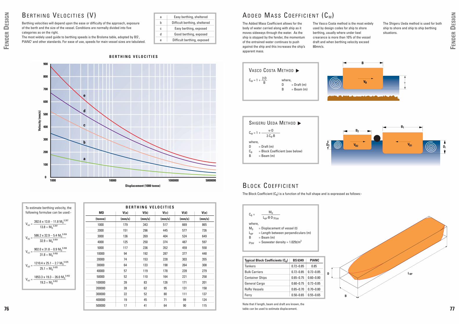
IGNBE R T H I N G VE L O C I T I E S (V)
Berthing velocities will depend upon the ease or difficulty of the approach, exposure of the berth and the size of the vessel. Conditions are normally divided into fivecategories as on the right.The most widely used guide to berthing speeds is the Brolsma table, adopted by BS1,PIANC2 and other standards. For ease of use, speeds for main vessel sizes are tabulated.
a Easy berthing, sheltered
b Difficult berthing, sheltered
c Easy berthing, exposed
d Good berthing, exposed
e Difficult berthing, exposed
Displacement (1000 tonne)
1000
e
0
100
200
300
400
500
600
700
800
900
Velo
city
(mm
/s)
5000000100000010000
d
c
b
a
B E R T H I N G V E L O C I T I E S
B E R T H I N G V E L O C I T I E SMD V(a) V(b) V(c) V(d) V(e)
(tonne) (mm/s) (mm/s) (mm/s) (mm/s) (mm/s)
1000 179 343 517 669 865
2000 151 296 445 577 726
3000 136 269 404 524 649
4000 125 250 374 487 597
5000 117 236 352 459 558
10000 94 192 287 377 448
20000 74 153 228 303 355
30000 64 133 198 264 308
40000 57 119 178 239 279
50000 52 110 164 221 258
100000 39 83 126 171 201
200000 28 62 95 131 158
300000 22 52 80 111 137
400000 19 45 71 99 124
500000 17 41 64 90 115
To estimate berthing velocity, thefollowing formulae can be used:-
V(a) = 392.6 x 13.8 – 11.8 MD
0.397
13.8 + MD0.397
V(b) = 586.2 x 32.9 – 5.4 MD
0.454
32.9 + MD0.454
V(c) = 902.0 x 31.8 – 0.9 MD
0.458
31.8 + MD0.458
V(d) = 1210.4 x 25.1 – 2.7 MD
0.435
25.1 + MD0.435
V(e) = 1853.3 x 19.3 – 26.0 MD
0.452
19.3 + MD0.452
D
B
L BP
B
DVB
AD D E D MA S S CO E F F I C I E N T (C M)The Added Mass Coefficient allows for thebody of water carried along with ship as itmoves sideways through the water. As theship is stopped by the fender, the momentumof the entrained water continues to pushagainst the ship and this increases the ship’sapparent mass.
The Vasco Costa method is the most widelyused by design codes for ship to shoreberthing, usually where under keelcrearance is more than 10% of the vesseldraft and when berthing velocity exceed80mm/s.
The Shigeru Ueda method is used for bothship to shore and ship to ship berthingsituations.
VB2 D1VB1D2
B2
B1SHIGERU UEDA METHOD
CM = 1 +
where,D = Draft (m)CB = Block Coefficient (see below)B = Beam (m)
▼
�.D2.CB.B
VASCO COSTA METHOD
CM = 1 + where,D = Draft (m)B = Beam (m)
▼
2.DB
BL O C K CO E F F I C I E N TThe Block Coefficient (CB) is a function of the hull shape and is expressed as follows:-
Note that if length, beam and draft are known, thetable can be used to estimate displacement.
CB =
where,MD = Displacement of vessel (t)LBP = Length between perpendiculars (m)B = Beam (m)�SW = Seawater density = 1.025t/m3
MD
LBP.B.D.�SW
Typical Block Coefficients (CB) BS 6349
Tankers 0.72~0.85 0.85
Bulk Carriers 0.72~0.85 0.72~0.85
Container Ships 0.65~0.75 0.60~0.80
General Cargo 0.60~0.75 0.72~0.85
RoRo Vessels 0.65~0.70 0.70~0.80
Ferry 0.50~0.65 0.55~0.65
PIANC

Some designers use the simplifiedformula for the Eccentricity Coefficientbelow. Care should be used as thismethod can lead to an underestimation ofberthing energy when the berthing angleis large (� 10°) and/or the point ofimpact is aft of quarter-point (x LBP/4).
VR
��
VB = V.sin �
VB
��R
a78
FEN
DER
DES
IGN
79
FEN
DER
DES
IGNEC C E N T R I C I T Y CO E F F I C I E N T (CE)
L O C K E N T R A N C E S A N D G U I D I N G F E N D E R SIn cases where the ship has a significant forward motion, it issuggested by PIANC that the ship’s speed parallel to the berthing face(V.cos �) is not decreased by berthing impacts and it is the transversevelocity component (V.sin �) which must be resisted by the fenders.When calculating the Eccentricity Coefficient, the velocity vectorangle (�) is taken between VB and R.
D O L P H I N B E R T H SShips will rarely berth exactly centrally against the berthing dolphins.The dolphin pairs are usually placed at 0.3-0.4 times the length of thedesign vessel. When calculating R and �, a dimension (a) ofapproximately 4-6% of the design vessel length is commonly assumed.Larger offsets will increase the Eccentricity Coefficient. In extremecases where VB is coaxial with the fender, CE = 1.
The Eccentricity Coefficient allows for the energy dissipated in rotation of the ship whenthe point of impact is not opposite the centre of mass of the vessel.
To determine the EccentricityCoefficient, you must firstly calculatethe radius of gyration (K), the distancefrom the vessels centre of mass to pointof impact (R) and the velocity vectorangle (�) using the following formulae:-
The Eccentricity Coefficient iscalculated using the followingformula:-
Values for the Eccentricity Coefficient generally fall within the following limits:-
where,
CB = Block coefficientLBP = Length between perpendiculars (m)x = Distance from bow to point of impactB = Beam (m)� = Berthing angle
K = [(0.19.CB) + 0.11] . LBP
R = x +LBP
2[ ]2 B
2[ ]2
� = 90° – � – a sinB
2.R[ ]
Quarter-point berthing
Third-point berthing
Mid-ships berthing
x =LBP
4CE � 0.4~0.6
CE � 0.6~0.8
CE � 1.0
x =LBP
3
x =LBP
2
CE = K2 + (R2.cos2(�))K2 + R2
CE �K2
K2 + R2
�
��
R
VB
�
L BP
x
�B/2
For � 5°, CC = 1
For � 5°, CC = 1
KC
D
KC
D
KC
D
The Berth Configuration Coefficient(CC) allows for the cushioning effect ofwater trapped between the vessel andthe berth. The value of CC will also be
affected by the berthing angle of the vessel.If this is greater than about 5°, then CCshould be taken as unity. Similarly, if theunder keel clearance (KC) is large relative to
the draft of the ship, then the trapped watercan easily escape under the vessel whichalso reduces the coefficient.
BE R T H CO N F I G U R AT I O N CO E F F I C I E N T (CC)
The Softness Coefficient (Cs) allowsfor the energy absorbed by elasticdeformation of the ship hull or by its
rubber belting. When a ‘soft’ fender is used(defined as having a deflection, �F, of morethan 150mm) then Cs is ignored.
SO F T N E S S CO E F F I C I E N T (C S)
CLOSED STRUCTURES
for 0.5 CC � 0.8KC
D�––
for 0.5 CC � 0.9KC
D
��
�
SEMI-CLOSED STRUCTURES
for 0.5 CC � 0.9KC
D�––
for 0.5 CC = 1.0KC
D
�
OPEN STRUCTURES
CC = 1.0
where,KC = Under keel clearance (m)D = Draft (m)
▼
▼
▼
for �F 150mm CS � 0.9�––
for �F 150mm CS = 1.0
�

80
FEN
DER
DES
IGN
81
FEN
DER
DES
IGNOnce all of the criteria and coefficients have
been established, the formula can be used tocalculate the ‘normal’ kinetic energy (EN) ofthe ship according to the mode of berthing.
NO R M A L BE R T H I N G
EN E R G Y (EN)
VB
V
V
S I D E B E R T H I N G
EN = 0.5.MD.(VB)2.CM
.CE.CS
.CC
D O L P H I N B E R T H I N G
EN = 0.5.MD.(VB)2.CM
.CE.CS
.CC
E N D B E R T H I N G
EN = 0.5.MD.V2
L O C K E N T R A N C E S
EN = 0.5.MD.(V.sin �)2.CM
.CE.CS
.CC
S H I P - T O - S H I P B E R T H I N G
EN = 0.5 . .(VB)2.CEMD1
.CM1.
+( ) MD2
.CM1( )MD1
.CM1( ) MD2.CM1( )[ ]
AB N O R M A L BE R T H I N G EN E R G Y (EA)Abnormal impacts may occur for many reasons – engine failure,breakage of towing lines, sudden weather changes or human error. BS1 suggests fenders be designed to include a safety factor of "up to"two times the normal berthing energy. PIANC11 suggests abnormalimpact safety factors be applied to the design (normal) energyaccording to the table below:-
LO A D FA C T O R SIn limit state designs, the load factors applied to fenderreactions under normal berthing are higher than those appliedunder abnormal berthing. Fenders are generally designed toabsorb the full abnormal energy, and the reaction will besimilar for both normal and abnormal impacts. In this instance,factored normal reactions often yield the worst design case. It is important to check both the normal and abnormal cases todetermine which results in the highest structural loads,moments and stresses.It is sometimes possible, depending on the fender andstructure types, to balance the normal and abnormal reactionsof the fender. This will optimise the design of both fender andstructure. Fentek can advise on whether this is feasible ineach case.
VB
VB
When selecting fenders for anapplication, the designer needs toconsider how the fender will be usedin service and the effects this mayhave on performance. Depending onthe project, factors may include:-
• Single or multiple fender contacts
• Effects of angular compression
• Fender efficiency (E/R)
• Temperature extremes
• Speed of approach
FE N D E R SE L E C T I O N
S I N G L E F E N D E R C O N T A C T• All energy absorbed by a single fender
• Full fender deflection likely
• Bow flare angle (�) is important
• 3-fender contact also possible when fenders are installed closer together
C O M P R E S S I O N A N G L E SWhere vessels berth with their curvedbow against the fender, the truecontact angle (�) will be less than theberthing angle (� ) due to the bowradius of the hull (RB). When theparallel mid-body of the ship contactsthe fender (i.e. on Dolphin berths), thecompression angle of the fender is thesame as the berthing angle. Thecompound angle (�) of � and � canbe estimated from the table below:-
� = Berthing angle� = Bow flare angleS = Fender to fender spacingRB = Bow radius� = Hull contact angle (on plan)� = Compound angle
T W O F E N D E R C O N T A C T• Energy shared over two fenders
• Compound angle (�) is important
• Hull-structure clearance (C) may be less, especially for small bow radii
S I N G L E O R M U L T I P L E F E N D E R C O N T A C T S
� = asinS
2.RB[ ]
Compound Angle : � = cos-1 (1+tan2 �+tan2 �)-0.5
2.8 4.5 6.3 8.2 10.2 12.2 14.1 16.1 18.1 20.1 2
5.7 7.2 8.9 10.7 12.6 14.5 16.4 18.4 20.3 4
8.5 10.0 11.6 13.4 15.2 17.0 18.9 20.8 6
11.3 12.7 14.3 16.0 17.7 19.5 21.3 8
14.0 15.5 17.0 18.6 20.3 22.0 10�
16.8 18.2 19.7 21.2 22.9 12
19.5 20.8 22.3 23.8 14
22.1 23.5 24.9 16
24.7 26.1 18
27.3 20
2 4 6 8 10 12 14 16 18 20Degrees
�
RB
S
O verhang due to
bow flare
�
RB
Overhang due to bow flare
�
ø (<�)
S/2
Type of Berth Vessel Safety Factor
Tankers and Bulk Cargo Largest 1.25
Smallest 1.75
Container Largest 1.5
Smallest 2.0
General Cargo 1.75
RoRo and Ferries 2.0 or higher
Tugs, Workboats etc 2.0

83
FEN
DER
PAN
ELSFE N D E R PA N E L DE S I G N
Fender panels (or ‘frames’) are used to distribute the reaction forces from the rubber fender units into the ship’s hull. They are generally offabricated steel composite beam construction and are designed to suit each individual berth. The loads and stresses applied to the panelswill depend on many factors - the type of ship, berthing mode, characteristics of the rubber fender unit, tidal range, positioning of restraintchains and many other variables.
Detail design is generally carried out using limit state design codes in conjunction with finite element and other computer modellingsoftware which needs to be specifically adapted for fender panels. Irrespective of the project, the general design requirements remainthe same in each case:-
• Resistance to bending moments and shear forces• Resistance to local buckling of internal member and webs• Stability of the front/back plates when in compression• Distribution of loads and stresses across panel members• Adequate weld types and sizes• Suitable corrosion protection for the intended environment
Most fender panels are now specified as “closed box” structures comprising of front and back plates plus a series of vertical andhorizontal stiffening members. Correctly designed closed box panels (as opposed to open box panels) are popular because:-
• Better strength to cost ratio• Lower maintenance (no corrosion traps)• Easier to inspect• Less prone to damage• Longer lasting
DE S I G N CA S E SThere are a number of commonly occurring cases whichdesigners needs to consider when specifying fender panels.
F U L L F A C E C O N T A C TThis case often arises with high freeboard vessels.Assuming basic dimensions and rubber fender unitcharacteristics are know, other loads and worst casebending moment may be calculated as follows:-
where,R = Reaction of rubber unit (kN)W = Uniform load across panel face (kN)F = Equilibrium load (kN)L = Contact length of panel face (m)Mmax = Maximum bending moment (kNm)MR = Moment at R (kNm)
a
b
L
F
W
R
R = W+F
F = 2.R L – aL 2[ ]
W = 2.R.aL
Mmax = MR = W.b2
= W.a2
+F.a2.L 2.L
for a = b = L F = O2
82
FEN
DER
SPA
CIN
G
R B
α
θ (<α)P U
CδF S/2S
T Y P I C A L B O W R A D I I
S ≤ 2 • �RB2-(RB-PU+�F+C)2
FE N D E R SPA C I N GIf fenders are spaced too far apart, it is possible forships with small bow radii to contact the structurewhen berthing at an angle to the quay face. Theoptimum clearance dimension (C) will vary fromproject to project according to vessel types,berthing conditions and the design of the structure. The minimum clearance is often in the range of5~15% of the uncompressed fender projection.
To calculate the maximum fender spacing, the bowradius (RB), fender projection (PU) and deflection(�F) should first be determined. The graphs below can be used to estimate the bowradius for different vessel types. In the absence ofadequate information about the ships, fendercentres should not be more than 15% of the overalllength of the smallest ship.where,
S = Centre to centre spacing of fenders (m)RB = Bow radius (m)PU = Uncompressed fender projection including rubber, panel etc (m)δF = Fender deflection (m)C = Clearance distance (m)
Notes:-
• Smaller ships usually have a smaller bow radius, but often have alower berthing energy as well so will not compress the fenders asmuch.A range of vessels which may use the berth should be checked todetermine the worst design case.
• The clearance distance will also need to take account of any bowflare angles.
• Bow flares are larger closer to the bow. However, the point of hullcontact with the fender is further away from the centre of mass ofthe vessel. This means that whilst the bow flare angle may be larger,the energy to be absorbed may be smaller.
RB~ 1
2 [ ]B LOA2
2 8B( )
Bow radius can be estimatedwith the following formula:-
( )+
C R U I S E L I N E R
C O N T A I N E R S H I PB U L K C A R R I E R
& G E N E R A L C A R G O S H I P
85
REST
RAIN
TCH
AIN
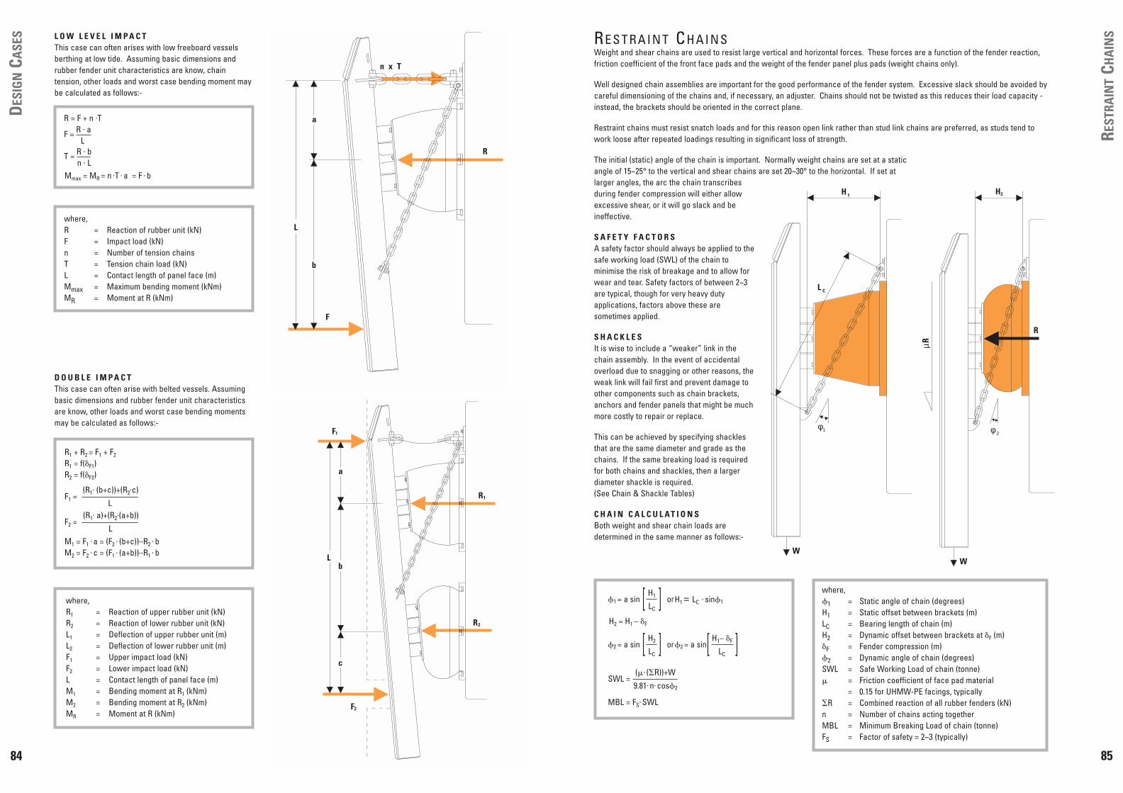
SRE S T R A I N T CH A I N SWeight and shear chains are used to resist large vertical and horizontal forces. These forces are a function of the fender reaction,friction coefficient of the front face pads and the weight of the fender panel plus pads (weight chains only).
Well designed chain assemblies are important for the good performance of the fender system. Excessive slack should be avoided bycareful dimensioning of the chains and, if necessary, an adjuster. Chains should not be twisted as this reduces their load capacity -instead, the brackets should be oriented in the correct plane.
Restraint chains must resist snatch loads and for this reason open link rather than stud link chains are preferred, as studs tend towork loose after repeated loadings resulting in significant loss of strength.
The initial (static) angle of the chain is important. Normally weight chains are set at a staticangle of 15~25° to the vertical and shear chains are set 20~30° to the horizontal. If set atlarger angles, the arc the chain transcribesduring fender compression will either allowexcessive shear, or it will go slack and beineffective.
S A F E T Y F A C T O R SA safety factor should always be applied to thesafe working load (SWL) of the chain tominimise the risk of breakage and to allow forwear and tear. Safety factors of between 2~3are typical, though for very heavy dutyapplications, factors above these aresometimes applied.
S H A C K L E SIt is wise to include a “weaker” link in thechain assembly. In the event of accidentaloverload due to snagging or other reasons, theweak link will fail first and prevent damage toother components such as chain brackets,anchors and fender panels that might be muchmore costly to repair or replace.
This can be achieved by specifying shacklesthat are the same diameter and grade as thechains. If the same breaking load is requiredfor both chains and shackles, then a largerdiameter shackle is required. (See Chain & Shackle Tables)
C H A I N C A L C U L A T I O N SBoth weight and shear chain loads aredetermined in the same manner as follows:-
where,�1 = Static angle of chain (degrees)H1 = Static offset between brackets (m)LC = Bearing length of chain (m)H2 = Dynamic offset between brackets at �F (m)�F = Fender compression (m)�2 = Dynamic angle of chain (degrees)SWL = Safe Working Load of chain (tonne)� = Friction coefficient of face pad material
= 0.15 for UHMW-PE facings, typically�R = Combined reaction of all rubber fenders (kN)n = Number of chains acting togetherMBL = Minimum Breaking Load of chain (tonne)FS = Factor of safety = 2~3 (typically)
φ2
H2
R
µR
W
φ1
L C
H 1
W
H2 = H1 – �F
�1 = a sin orH1 = LC . sin�1
H1
LC[ ]
�2 = a sin or�2 = a sinH2
LC[ ]
SWL =
MBL = FS. SWL
(�. (�R))+W
9.81. n. cos�2
H1– �F
LC[ ]
84
DES
IGN
CASE
S
L
a
b
c
F1
R1
R2
F2
a
b
L
F
n Tx
R
L O W L E V E L I M P A C TThis case can often arises with low freeboard vesselsberthing at low tide. Assuming basic dimensions andrubber fender unit characteristics are know, chaintension, other loads and worst case bending moment maybe calculated as follows:-
where,R = Reaction of rubber unit (kN)F = Impact load (kN)n = Number of tension chainsT = Tension chain load (kN)L = Contact length of panel face (m)Mmax = Maximum bending moment (kNm)MR = Moment at R (kNm)
D O U B L E I M P A C TThis case can often arise with belted vessels. Assumingbasic dimensions and rubber fender unit characteristicsare know, other loads and worst case bending momentsmay be calculated as follows:-
where,R1 = Reaction of upper rubber unit (kN)R2 = Reaction of lower rubber unit (kN)L1 = Deflection of upper rubber unit (m)L2 = Deflection of lower rubber unit (m)F1 = Upper impact load (kN)F2 = Lower impact load (kN)L = Contact length of panel face (m)M1 = Bending moment at R1 (kNm)M2 = Bending moment at R2 (kNm)MR = Moment at R (kNm)
Mmax = MR = n .T . a = F . b
M1 = F1 . a = (F2
. (b+c))–R2 . b
M2 = F2 . c = (F1
. (a+b))–R1 . b
R1 + R2 = F1 + F2
R1 = f(�F1)R2 = f(�F2)
F1 =(R1
. (b+c))+(R2.c)
L
F2 =(R1
. a)+(R2.(a+b))
L
R = F + n .T
F = R . aL
T = R . bn . L

87
RUB
BER
PRO
PERT
IESRU B B E R PR O P E R T I E S
Fentek rubber fender components are manufactured from the highest quality Natural Rubber (NR), optionally Styrene Butadiene SBRbased compounds which meet or exceed the performance requirements of European Union specification EAU-E 62 “AcceptanceRequirements for Fender Elastomers”. Typical specifications are listed in the table below.
In addition to NR and SBR, other rubber compounds in Butyl, EPDM, and Polyurethane are available on request for specialistapplications. Please consult Fentek for further details.
The above values are for tests carried out under strict laboratory conditions using specimens taken from batches of unvulcanisedrubber compound.
Property Testing Standard Condition Requirement
Tensile Strength
Elongation at Break
ASTM D412 Die C; AS 1180.2; BS 903.A2;ISO 37; JIS K6301 Item 3, Dumbell 3
DIN 53504
Original 16MPa (Min)
Aged for 96 hours at70˚C
Original
Aged for 168 hoursat 70˚C
12.8MPa (Min)
15N/mm2 (Min)
12.75N/mm2 (Min)
ASTM D412 Die C; AS 1180.2; BS 903.A2;ISO 37; JIS K6301 Item 3, Dumbell 3
DIN 53504
Original 400% (Min)
Aged for 96 hours at70˚C
Original
Aged for 168 hours at70˚C
320% (Min)
300% (Min)
280% (Min)
Hardness
DIN 53505
DIN 53517
OriginalAged for 96 Hoursat 70˚C
78° (Max) Shore AOriginal Value + 6°points increase
Original
Aged for 168 hours at70˚C
75° (Max) Shore A
Compression SetASTM D395; AS 1683.13B; BS 903.A6; ISO 815; JIS K6301 Item 10
Aged for 22 hours at70˚C
30% (Max)
Aged for 24 hours at 70˚C 40% (Max)
DIN 53507
Tear ResistanceASTM D624; AS 1683.12; BS 903.A3; ISO 34.1; JIS K6301 Item 9, Test Piece A
Die B 70kN/m (Min)
Ozone ResistanceASTM D1149; AS 1683.24; BS 903.A43; DIN 53509; ISO 143/1
1ppm at 20% strain at40°C for 100 hours
No cracking visibleby eye
Seawater Resistance DIN 86076, Section 7.728 days in artificialseawater at 95˚C ±2˚C
Hardness ±10° (Max)Shore AVolume +10/-5% (Max)
Abrasion ResistanceBS 903.A9
DIN 53516
Method B, 1000revolutions
0.5cc (Max)
Bond StrengthSteel to Rubber
BS 903.A21 Method B 7N/mm (Min)
100mm3 (Max)
80 N/cm (Min)
Original Value + 5°points increase
ASTM D2240; AS 1683.15.2; BS 903.A6; ISO 815; JIS K6301 Item 5A Tester
86
H1
W1
H2
W2
Material Friction Coefficient (�)UHMW-PE to Steel (wet) ≤0.10UHMW-PE to Steel (dry) 0.10~0.15HD-PE to Steel 0.20~0.25Rubber to Steel 0.50~1.00Timber to Steel 0.30~0.50
ULCC & VLCC 150~250 kN/m2
Tankers 250~350 kN/m2
Product & Chemical Tankers 300~400 kN/m2
Bulk Carriers 150~250 kN/m2
Post-Panamax Container Ships 200~300 kN/m2
Panamax Container Ships 300~400 kN/m2
Sub-Panamax Container Ships 400~500 kN/m2
General Cargo (un-belted) 300~600 kN/m2
Gas Carriers 100~200 kN/m2
Arch Fenders: 760~1300kN/m2
Cylindrical Fenders: 460~780kN/m2
where,P = Hull pressure (kN/m2)�R = Combined reaction of all rubber fenders (kN)W2 = Panel width excluding lead-in chamfers (m)H2 = Panel height excluding lead-in chamfers (m)PP = Permissible hull pressure (kN/m2)
FRIC
TIO
NCO
EFFI
CIEN
TS/H
ULL
PRES
SURE
S F R I C T I O N C O E F F I C I E N T SFriction coefficients have a large influence on the size of shear chains. It isrecommended that low friction materials such as UHMW-PE are used to facefender panels which will reduce shear forces applied to the berth structure.
Typical friction coefficients for different materials are given below:-
HU L L PR E S S U R E SPermissible hull pressures vary greatly with the class and size of ship. The best guide to hull pressures is experience of similar installations. Where this information is unavailable, then the following table may be used asan approximate guide for design (refer to Ship Tables on pages 70-72 for vesselsizes).
Hull pressures are calculated using the nett panel area (excluding lead-inchamfers) as follows:-
O T H E R F E N D E R T Y P E SThe above calculations and table apply to berths fitted with fender panelsystems. However, many berths have used Cylindrical and Arch fenderssuccessfully and without ship damage, despite the fact that these fendersexert higher hull pressures, typically:-
Also bear in mind that when cylindrical fenders are used with large chain orbar fixings through the central bore, these may locally increase hull pressuresto approximately double the above figures. Again there is no evidence toshow that this causes hull damage.
P = PP
�R
W2. H2
��

89
TOLE
RAN
CES
88
PERF
ORM
AN
CETE
STIN
G P E R F O R M A N C E T E S T I N GMoulded1 and wrapped cylindrical2 fenders are routinely tested as a part of Fentek’s commitment to quality. All testing is conductedin-house, with the option of third party witnessing, using full size fenders in accordance with the PIANC3 guidelines below.
i) All fender units shall be given a unique serial number which can be traced back to manufacturing and testing records.ii) Fenders shall be tested under direct (vertical) compression.iii) Compression speed shall be 2~8 cm/min.iv) Test temperature shall be 23°C ±5°C4.v) Reaction force5 shall be recorded at intervals to at least a deflection at which the permitted6 minimum energy absorption is
achieved.vi) Energy absorption5 shall be determined as the integral of reaction and deflection, calculated using Simpson’s Rule.vii) The result of the first compression cycle shall not be recorded.viii) The average performance from the second and third compression cycles shall be less than the permitted6 maximum reaction
and more than the permitted6 minimum energy absorption.ix) Sampling shall be 1 in 10 fenders (rounded up to a unit)x) If any sample does not satisfy the specifications, sampling of the remainder shall be increased to 1 in 5 fenders (rounded up to
a unit), excluding non-compliant units.xi) If any further sample does not satisfy the specifications, all remaining samples shall be tested. Only units which satisfy the
specifications shall be passed for shipment.xii) Non-compliant units shall be clearly marked and isolated.
Where Super Cone and Unit Element fenders are required for "load sensitive" structures, it is suggested that fender testing frequencybe increased8 in accordance with the following tables:-
1 Moulded fenders include Super Cones, Unit Elements and AN/ANP Arch fenders. Super Cone and AN/ANP Arch fenders aretested singly, Unit Element fenders are tested in pairs.
2 Excluding tug cylindrical fenders.3 PIANC – Permanent International Association of Navigation Congresses
Report of the International Commission for Improving the Design of Fender SystemsSupplement to Bulletin No 45 (1984) – Annex 4.1 (pages 85~87)
4 Where ambient temperature is outside of this range, fenders shall be normalised to this temperature range in a conditioning roomfor an appropriate period (dependent upon fender size) or performance values may be corrected according to temperaturecorrection factor tables.
5 Reaction force (and corresponding calculated energy absorption) shall be the exact recorded value and not corrected orotherwise adjusted for speed correction unless required by the project specifications.
6 Permitted values for reaction and energy are catalogue values and applicable manufacturing tolerances.7 The deflection at which minimum energy permitted energy absorption is achieved may differ from the nominal "rated" deflection
indicated in the catalogue for the relevant fender type.8 Standard PIANC testing is included within the fender price. Additional testing frequency, third party witnessing and temperature
conditioning costs are borne by the purchaser.9 Pre-compression testing involves a single "run in" cycle up to catalogue rated deflection. Reaction force is not recorded for pre-
compression testing.
P E R F O R M A N C E T E S T I N GFender Height Pre-Compression9 PIANC Testing
H ≤ 900mm 20~25% of units 10% of units
900mm < H ≤ 1300mm 100% of units 20~30% of units
H > 1300mm N/A 100% of units
C H A N G E S T O F E N D E R T E S T I N G
In April 2002, PIANC Working Group 33 of the Maritime Navigation Commission published its report on "Guidelines for the Designof Fender Systems : 2002" which has been widely welcomed and adopted by fender designers and specifiers. It also introducesa new "Procedure to Determine and Report the Performance of Marine Fenders" in Appendix A.
This new test protocol requires manufacturers to undergo a series of type approval tests for each significant fender type theymake, to define the effects on performance of different deflection rates, temperatures, berthing frequencies and compressionangles. In addition, the protocol suggests more stringent and frequent quality control testing.
Due to its complexity, it will take manufacturers some time to phase in the new protocol. Please contact Fentek for furtherdetails and timescale, as well as copies of type approval certificates.
To order a copy of the PIANC WG33 Report or to join the PIANC organisation, please visit www.pianc-aipcn.org.
TO L E R A N C E SAll Fentek fenders are subject to standard manufacturing and performance tolerances. For specific applications, smaller tolerancesmay be agreed on a case by case basis.
1 Whichever is the greater dimension.2 All values are measured at 18°C and subject to thermal expansion coefficients (see material properties).3 Please consult Fentek for performance tolerance on fender types not listed above.
Manufacturing Tolerances
Moulded FendersAll dimensions
Bolt hole spacing±3% or ±2mm1
±2mm
Composite Fenders
Cross-sectionLength
Drilled hole centresCounterbore depth
±3% or ±2mm1
±2% or ±25mm1
±4mm (non-cumulative)±2mm (under head depth)
Block FendersCube FendersM Fenders
Cross-sectionLength
Fixing hole centresFixing hole diameter
±2% or ±2mm1
±2% or ±10mm1
±3mm±3mm
Cylindricals FendersOutside diameterInside diameter
Length
±4%±4%
-0/+40mm
Extruded Fenders
Cross-sectionLength
Drilled hole centresCounterbore depth
±4%-0/+40mm
±4mm (non-cumulative)±2mm (under head depth)
HD-PE Sliding Fenders2
Cross-sectionLength
Drilled hole centresCounterbore depth
±4% or ±1mm (planed)±10mm
±2mm (non-cumulative)±2mm (under head depth)
UHMW-PE Face Pads2
Length & width& width
Thickness: ≤ 30mm(Planed) 31~100mm
≥ 101mm
Thickness: ≥ 30mm(Unplaned) 31~100mm
≥ 101mm
Drilled hole centresCounterbore depth
±5mm (cut pads)±20mm (uncut sheets)
±0.2mm±0.3mm±0.5mm
±2.5mm±4.0mm±6.0mm
±2mm (non-cumulative)±2mm (under head depth)
SCN, UE, AN & ANP Reaction, Energy & Deflection
Cylindricals (Wrapped ) Reaction, Energy & Deflection ±10%
Cylindricals (Extruded) Reaction, Energy & Deflection ±20%
Extruded Fenders Reaction, Energy & Deflection ±20%
Pneumatic FendersReaction & Energy
Deflection±10%±5%
Foam FendersReaction & Energy
Deflection±15%±5%
Block, Cube & M-Fenders Reaction & Deflection ±10%
Performance Tolerances 3
±10% (E1, E2 & E3)

91
PRO
JECT
REQ
UIR
EMEN
TSPR O J E C T RE Q U I R E M E N T S
PORT
PROJECT
CONSULTANT
CONTRACTOR
S H I P D E T A I L S
B E R T H D E T A I L S
FENTEK REF:
❑ PROJECT STATUS
❑ PRELIMINARY
❑ DETAIL DESIGN
❑ TENDER
B
D
F
LOA
LBP
❑ CLOSED STRUCTURE
❑ SEMI-OPEN
❑ OPEN STRUCTURE
❑ OTHER (PLEASE DESCRIBE)
Largest Vessel...................................................................................... Smallest Vessel.......................................................................................
Vessel Type ........................................................................................... Vessel Type ..............................................................................................
Deadweight.......................................................................................(t) Deadweight ..........................................................................................(t)
Displacement....................................................................................(t) Displacement .......................................................................................(t)
Length Overall (LOA) .......................................................................(m) Length Overall (LOA)...........................................................................(m)
Length Between Perps (LBP) ........................................................(m) Length Between Perps (LBP)............................................................(m)
Beam (B)..........................................................................................(m) Beam (B) .............................................................................................(m)
Draft (D) ...........................................................................................(m) Draft (D)...............................................................................................(m)
Freeboard (F) ..................................................................................(m) Freeboard (F) ......................................................................................(m)
Hull Pressure (P).........................................................................(t/m2) Hull Pressure (P)...........................................................................(t/m_)
Structure . . . . . . . . . . . . . . . . . . . . . . . . . . . . . . . . . . . . . . . . . . . . . Tide Levels . . . . . . . . . . . . . . . . . . . . . . . . . . . . . . . . . . . . . . . . . . . . .
Length of Berth . . . . . . . . . . . . . . . . . . . . . . . . . . . . . . . . . . . . . (m) Tidal Range . . . . . . . . . . . . . . . . . . . . . . . . . . . . . . . . . . . . . . . . . . . m
Fender/Dolphin Spacing . . . . . . . . . . . . . . . . . . . . . . . . . . . . . . (m) Highest Astronomic Tide (HAT) . . . . . . . . . . . . . . . . . . . . . . . . . . . m
Permitted Fender Reaction. . . . . . . . . . . . . . . . . . . . . . . . . . . (kN) Mean High Water Spring (MHWS) . . . . . . . . . . . . . . . . . . . . . . . . m
Quay Level . . . . . . . . . . . . . . . . . . . . . . . . . . . . . . . . . . . . . . . . . (m) Mean Sea Level (MSL) . . . . . . . . . . . . . . . . . . . . . . . . . . . . . . . . . . m
Cope Thickness . . . . . . . . . . . . . . . . . . . . . . . . . . . . . . . . . . . . . (m) Mean Low Water Spring (MLWS) . . . . . . . . . . . . . . . . . . . . . . . . . m
Seabed Level . . . . . . . . . . . . . . . . . . . . . . . . . . . . . . . . . . . . . . . (m) Lowest Astronomic Tide (LAT) . . . . . . . . . . . . . . . . . . . . . . . . . . . . m
90
USE
FUL
INFO
RMAT
ION OT H E R US E F U L IN F O R M AT I O N
D I S T A N C E k m m i l e n m1 km = 1 0.6214 0.5400
1 mile = 1.6093 1 0.8690
1 nm = 1.8519 1.1508 1
L E N G T H m i n1 m = 1 39.372
1 in = 0.025 1
1 ft = 0.3048 12
1 yd = 0.9144 36
ACCELERATION g m / s 2 f t / s 2
1 g = 1 9.807 32.17
1 m/s2 = 0.102 1 3.281
1 ft/s2 = 0.0311 0.3048 1
A R E A m 2 i n 2
1 m2 = 1 1550
1 in2 = 0.000645 1
1 ft2 = 0.0929 144
1 yd2 = 0.8361 1296
V E L O C I T Y m / s k m / h f t / s m p h k n o t1 m/s = 1 3.600 3.281 2.237 1.944
1 km/h = 0.2778 1 0.9114 0.6214 0.5400
1 ft/s = 0.3048 1.0972 1 0.6818 0.5925
1 mph = 0.4470 1.6093 1.4667 1 0.8690
1 knot = 0.5144 1.8518 1.6877 1.1507 1
P R E S S U R E b a r M P a l b / i n 2 t / m 2 k i p / f t 2
1 bar = 1 0.1 14.5 0.102 2.089
1 MPa = 10 1 145 1.019 20.89
1 lb/in2 = 0.06897 0.006897 1 0.7031 0.144
1 t/m2 = 9.807 0.9807 1.4223 1 0.2048
1 kip/ft2 = 0.4787 1 6.9444 4.8828 1
M A S S k g t o n n e l b k i p1 kg = 1 0.0010 2.205 0.002205
1 tonne = 1000 1 2205 2.2046
1 lb = 0.4536 0.000453 1 0.0010
1 kip = 453.6 0.4536 1000 1
E N E R G Y 1 kNm (kJ)
1 kNm (kJ) = 1
1 tonne-m = 9.807
1 ft.kip = 1.356
D E N S I T Y1 kg/m3 = 0.06243 lb/ft3
1 lb/ft3 = 16.0185 kg/m3
F O R C E1 kN = 0.2248 kipf
1 kipf = 4.449 kN
Information is provided for guidance only.Reference should be made to EN 10 025 : 1993 for more specific properties.
C O N V E R S I O N T A B L E S
EN 10 025:1993 Formerly Yield (N/mm2) Temp (°C) Germany France UK Spain Italy Belgium Sweden Portugal NorwayS 185 Fe 310-0 185 — St 33 A 33 A 310-0 Fe 320 A 320 13 00-00 Fe 310-0S 235 Fe 360 A 235 — St 37-1 E 24-1 Fe 360 A AE 235-A Fe 360-AS 235JR Fe 360 B 235 +20 St 37-2 E 24-2 Fe 360 B AE 235-B 13 11-00 Fe 360-B NS 12 120S 235JRG1 Fe 360 B(FU) 235 +20 USt 37-2 40 A AE 235 B-FU NS 12 122S 235JRG2 Fe 360 B(FN) 235 +20 RSt 37-2 40 B AE 235 B-FN 13 12-00 NS 12 123S 235JO Fe 360 C 235 0 ST 37-3 U E 24-3 40 C AE 235 C Fe 360 C AE 235-C Fe 360-C NS 12 124S235JOG3 Fe 360 D1 235 -20 ST 37-3 N E 24-4 40 D AE 235 D Fe 360 D AE 235-D Fe 360-D NS 12 124S235JOG4 Fe 360 D2 235 -20 E 24-4 40 D AE 235 D Fe 360 D AE 235-D Fe 360-D NS 12 124S 275 Fe 430 A 275 — St 44-1 E 28-1 43 A AE 275 A Fe 430 A AE 255-A Fe 430-AS 275JR Fe 430 B 275 +20 St 44-2 E 28-2 43 B AE 275 B Fe 430 B AE 255-B 14 12-00 Fe 430-B NS 12 142S 275JO Fe 430 C 275 +0 St 44-3 U E 28-3 43 C AE 275 C Fe 430 C AE 255-C Fe 430-C NS 12 143S 275J2G3 Fe 430 D1 275 -20 St 44-3 N E28-4 43 D AE 275 D Fe 430 D AE 255-D 14 14-00 Fe 430-D NS 12 143S 275J2G4 Fe 430 D2 275 -20 E28-4 43 D AE 275 D Fe 430 D AE 255-D 14-14-01 Fe 430-D NS 12 143S 355 Fe 510 A 355 — E 36-1 50 A AE 355 A Fe 510 A AE 355-A Fe 510-AS 355JR Fe 510 B 355 +20 E 36-2 50 B AE 355 B Fe 510 B AE 355-B Fe 510-BS 355JO Fe 510 C 355 0 St 52-3 U E 36-3 50 C AE 355 C Fe 510 C AE 355-C Fe 510-C NS 12 153S 355J2G3 Fe 510 D1 355 -20 St 52-3 N 50 D AE 355 D Fe 510 D AE 355-D Fe 510-D NS 12 153S 355J2G4 Fe 510 D2 355 -20 50 D AE 355 D Fe 510 D AE 355-D Fe 510-D NS 12 153S 355K2G3 Fe 510 DD1 355 -20 E 36-4 50 DD AE 355-DD Fe 510-DDS 355K2G4 Fe 510 DD2 355 -20 E 36-4 50 DD AE 355-DD Fe 510-DD
A comparison between former national steel designations, now superseded by EN 10 025S T E E L E Q U I V A L E N T S T A B L E S

9392
PRO
JECT
REQ
UIR
EMEN
TS B E R T H I N G M O D E
❑ Side Berthing
❑ Dolphin Berthing
❑ End Berthing
❑ Dolphin Berthing
❑ Lock or Dock Entrance
❑ Ship-to-Ship Berthing
❑ Other Berthing Mode . . . . . . . . . . .
. . . . . . . . . . . . . . . . . . . . . . . . . . . . . . . .
. . . . . . . . . . . . . . . . . . . . . . . . . . . . . . . .
B E R T H I N G A P P R O A C H
Approach Conditions
❑ a) Easy berthing, sheltered
❑ b) Difficult berthing, sheltered
❑ c) Easy berthing, exposed
❑ d) Good berthing, exposed
❑ e) Difficult berthing, exposed
Largest Ship
Berthing Speed . . . . . . . . . . . . . . . . . . (m/s)
Berthing Angle. . . . . . . . . . . . . . . . . . . (deg)
Safety Factor on Energy . . . . . . . . . . . . . . .
Smallest Ship
Berthing Speed . . . . . . . . . . . . . . . . . . (m/s)
Berthing Angle. . . . . . . . . . . . . . . . . . . (deg)
Safety Factor on Energy . . . . . . . . . . . . . . .
F U R T H E R I N F O R M AT I O N I S A V A I L A B L E F R O M
Name . . . . . . . . . . . . . . . . . . . . . . . . . . . . . . . . . . . . . . . . . . . . . . . . . . . . . . . . . . . . . . . . . . . . . . . . . . . . . . . . . . . . . . . . . . . . . . . . . . . . . . . . . . . . .
Position . . . . . . . . . . . . . . . . . . . . . . . . . . . . . . . . . . . . . . . . . . . . . . . . . .
Company . . . . . . . . . . . . . . . . . . . . . . . . . . . . . . . . . . . . . . . . . . . . . . . . .
Tel . . . . . . . . . . . . . . . . . . . . . . . . . . . . . . . . . . . . . . . . . . . . . . . . . . . . . . .
Fax . . . . . . . . . . . . . . . . . . . . . . . . . . . . . . . . . . . . . . . . . . . . . . . . . . . . . .
Email. . . . . . . . . . . . . . . . . . . . . . . . . . . . . . . . . . . . . . . . . . . . . . . . . . . . .
O T H E R I N F O R M A T I O N
S O U R C E S O F F U R T H E R I N F O R M A T I O N
1. Code of Practice for Design of Fendering and Mooring SystemsBS 6349 : Part 4 : 1994 (ISBN 0-580-22653-0)
2. Recommendations of the Committee for Waterfront StructuresEAU 1990 (ISBN 3-433-01237-7)
3. Report of the International Commission for Improving the Design of Fender SystemsSupplement to Bulletin No.45 (1984) PIANC
4. Maritime Works Recommendations - Actions in the Design of Maritime and Harbour WorksROM 0.2-90 (ISBN 84-7433-721-6).
5. Ship Dimensions of Design Ship under Given Confidence LimitsTechnical Note of the Port and Harbour Research Institute, Ministry of Transport, JapanNo. 911, Sept 1998 (ISSN 0454-4668)
6. Approach Channels – A Guide to DesignSupplement to Bulletin No.95 (1997) PIANC (ISBN 2-87223-087-4)
7. Port Design – Guidelines and RecommendationsCarl A. Thoresen (ISBN 82-519-0839-6)
8. On Fender Design and Berthing Velocities – 24th PIANC CongressJ.U. Brolsma et al
9. The Berthing ShipF. Vasco Costa
10. Significant Ships - Royal Institute of Naval Architects11. PIANC WG33 Guidelines for the Design of Fenders : 2002 (ISBN 2-87223-125-0)
AcknowledgementsFentek gratefully acknowledges the cooperation and assistance provided by many individuals and companies in the preparation of thiscatalogue and associated publications.
Arch Henderson & PartnersCaledonian MacBrayne FerriesMaik Ebel PhotographyJ. Gaston Photography P&O NedlloydStena Line Ltdour many Agents & Distributors
DisclaimerFentek has made every effort to ensure that the technical specifications and product descriptions in this catalogue are correct. The responsibility or liability for errors and omissions cannot be accepted for whatever reason. Customers are advised to request adetailed specification and certified drawing from Fentek prior to construction and manufacture. In the interests of improving the qualityand performance of Fentek products and systems, we reserve the right to make specification changes without prior notice. All dimensions,material properties and performance values quoted are subject to normal production tolerances. This catalogue supersedes theinformation provided in all previous editions. If in doubt, please check with Fentek.
© 2001 Fentek Marine Systems GmbHThis catalogue is the copyright of Fentek Marine Systems GmbH and may not be reproduced, copied or distributed to third parties withoutthe prior consent of Fentek in each case.Fentek® is a Registered Trade Mark of Fentek Marine Systems GmbH