Fem Design Eng
12
-
Upload
designmukesh -
Category
Documents
-
view
137 -
download
1
description
fem design
Transcript of Fem Design Eng

IntegerInteger
NorconsultNorconsult
StruSoftStruSoft
StruSoftStruSoft
Nord EngineeringNord Engineering
ArutecArutec
StruSoftStruSoft
MódiStudióMódiStudióSPC ProjectSPC Project

�
FEM-Design suite
FEM-Design is a group of modules that offers a powerful analysis and design environment using finite element methods.
Single elements or a complete building, made from any number of materials and structural elements can be analysed with ease. The users can create one central model to analyse their complete structure or focus solely on the analysis and design of specific horizontal or vertical planes or single elements.
From initial tendering stages to complete building analysis, FEM-Design offers a powerful, yet easy to use package that can be tailored to suite the exact analysis and design needs of the engineer and the job in hand.
Key features include:Intelligent data connections. Quickly and easily create your model from your architects’ layout by importing of IFC, DXF and DWG files.
Analyse your applied design reinforcement including the ability to specify data for the cracked section analysis iteration.
Quickly and accurately check the stability of your structure. Check designs for steel with automatic calculations of utilisation with critical members highlighted on-screen.
Manage project changes easily. Create one quality report from within the program with interactive graphical windows to your design model and all results views.
FEM Design suite module summary:Plate, Wall, 3D Frame, 3D Structure.
Accessory modules; PreDesign, Documentation Editor, Section Editor.
Easy-to-use drawing & CAD toolsUser-friendly working interface
Easy modelling in 2D and 3D
Powerful and easy to use analysis and design from one central 3D model. Utilise the power of FE for your designs of:Concrete slabsShear wallsSteel frames3D shell structures & Complex 3D structures

3
FEM-Design overall package features
Modelling
• Simple and user friendly working environment with intuitive CAD tools for easy model creation and editing
• OpenGL for fast fly through rendered views, animated results and powerful 2D and 3D graphical representation of input geometry and results
• Intelligent data connections provide options to import DXF, DWG or IFC files for quick model creation
• Point-point, line-line and edge connections between structural objects for real life situation modelling
• Point, line and surface supports with rigid, free and/or elastic stiffness components
• Section editor for defining custom section shapes for bars, beams and columns with automatic property calculation
• Inbuilt structure wizard for quick and easy input of slab and frame systems
Analysis
• Various loading types including, point, line, surface, temperature, support motion and stress loads. Automatic wind and snow loading are also available
• Automatic loading combinations for unfavourable loads, combing permanent, variable and accidental loads
• Automatic optimal finite element mesh generation for any geometry with no element limit and the ability to mesh to load positions if required
• Options for advanced static, dynamic (eigen frequencies), stability and seismic analysis. FEM-Design can automatically convert load cases to masses for dynamic calculations and surface loads into line loads in frame structures
• Automatic solving of singularity problems in internal/design force results above supports
Design
• Choose your desired design code for reinfor cement and steel from 10 national standards, including British, Danish, Eurocodes, Hungarian, Norwegian and Swedish.
• Steel design includes automatic utilisation checks for stresses, flexural buckling, LTB and web and flange buckling
• Choose your preferred results display from 3D graphs, contour lines, colour palette or sections for each display result
• Documentation editor, for quality multi-page documentation within the FEM-Design environment
• Input and output data can be generated in tabular form with the ability to use Microsoft Excel
Complete solution for structural design and documentation
Professional and unique built-in finite element mesh generator

�
FEM-Design Plate
FEM-Design plate offers a powerful and easy way to design concrete slab systems according to actual concrete behaviour. Features of the module include powerful cracked section analysis, punching calcula-tions, shrinkage effects, and the ability to apply and analyse user defined reinforcement.
The basic outline model can be generated by the programs own CAD tools or imported via DXF/DWG or model based IFC links. The structural elements are defined with easy to use tools for plate regions, beams, column and wall supports. An inbuilt structure wizard is also available. This can be used to generate regular models including all structural elements and the applied loading.
The programs powerful mesh generator automati-cally produces a mesh adjusted to the current geome-try, support and loading conditions. Designs can then be carried out according to EC� and 9 other national codes with features such as cracked section analysis, shrinkage behaviour and punching shear calculations all taken into account.
There are several easy-to-use tools for defining the “accurate” static model: absolute and relative coor-dinates, user-coordinate system, drawing and editing tools, region operations, special point editors, object snap tools, layer system, etc. There is no geometrical limit and plates can be created with any shape and thickness values, beams/columns with any section and walls with variable thicknesses, walls with variable thickness, etc.
Further special features are also available, such as designs of slabs with varying thickness, modelling of orthotropic material behaviour and checking of plate corners for uplift above supports.
Powerful reinforcement designAn initial calculation provides required top and bot-tom bending reinforcement across the whole slab, together with the corresponding punching shear capacities, deflection results and crack widths. On the basis of the above results the user can define the desired (applied) reinforcement in any shape and direction.
The Växjö Library FEM-Design model images (left) show an example of the required reinforcement results. Areas in red highlight that not enough top reinforcement in the X direcion has been provided.
The RC design module also suggests additional reinforcement required after taking punching shear into account. In addition to the numerical output, the columns are displayed in different colours depending
12 storey building in Linköping, Sweden with Offices, Laboratory for Biotechnology and Shopping Centre. The total gross floor area is 9000 m2. The staircases of post-tensioned concrete are used for stabilizing the building. The construction work started in April 2002 and was finished in December 2003.Structural Engineer: CSE Civil & Structural Engineering Projekt AB
Växjö LibraryThe library is a three-storey building with a diameter of 38 m. Structural design: Sycon Teknikkonsult AB. (FEM-Design model views of applied and required reinforcement & punching checking of slab above columns.)
Model built from a DWG drawing.

�
on the shear capacity with or without any additional shear reinforcement (e.g. green columns indicate that the shear capacity is OK with existing reinforcement, and red means that the shear capacity is too small even with additional shear reinforcement).
Cracked-section analysisDeflections may be calculated using cracked-section analysis applied for serviceability load combinations and user-defined reinforcement. As well as deflection results, crack width and crack direction (crack lines) results can also be requested.
As an example, FEM-Design Plate module was used in the design of The Chimes Shopping Centre, Uxbridge, because of the great flexibility offered in placing future openings in the slab. The program also provided substantial savings in the reinforcement design compared with conventional methods.
Peak smoothing procedureFEM-Design gives an automatic solution for addressing the singularity problem (peaks) of internal and design force results above supports. Automatic peak smoo-thing regions can be applied by the program in user specified locations (e.g. over columns, at beam and wall end points, etc.). These regions provide more realistic results and are calculated based on the column, beam or wall size and the thickness of the plate.
Geometry Import/ExportTwo types of geometry import can be carried out in FEM-Design: DWG/DXF drawing and model-based IFC.
Design of ribbed slabsIn FEM-Design Plate, beams under the slab (i.e. rib-bed slabs) can be modelled for static analysis inclu-ding internal forces and displacement. The design results for design forces, areas of required rc and crack widths can all be dispalyed in various forms.
4 simple steps to concrete design:
1st step: Run the concrete design and analysis to obtain the required reinforcement and punching results.
2nd step: Define (applied) top/bottom reinforce-ment in the slab taking into consideration the previous design results.
3rd step: Run a check on the applied reinforce-ment combined with cracked-section analysis.
Plate Module – Structure, FE mesh & design forces
4th step: Analyse the deflection, crack width and missing reinforcement results and increase the reinforcement if needed. Repeat the checking process until the optimal reinforcement design is achieved.
FEM-Design Plate features
• Analyse and design slab systems with variable thickness and different materials
• Accurate modelling of orthotropic behaviour
• Uplift allowed above supports
• Wall and column supports
• Modelling of beams under slabs
• Dynamic analysis of vibration (eigen frequencies and vibration shapes)
• Concrete design calculations to several national codes.
• Consideration of shrinkage behaviour
• Shear capacity check
• Punching checking above columns
• Crack width/crack line distribution
• User-defined surface (applied) reinforcement as required reinforcement results
• Cracked section and displacement analysis of user defined applied reinforcement
• Required reinforcement in slabs (top and botton) and beams (longitudinal bars and links)
• IFC connection for designing 3D structures by storeys (e.g. connection with ArchiCAD)

�
FEM-Design Wall
Within FEM-Design Wall, arbitrary �D structures loaded in their own plane (stress in z-direction, σz=0) can be analysed for static and dynamic calculation and reinforcement design.
The Wall (plane stress) module offers design solutions for shear and load bearing walls, and also for other kinds of structural elements, such as webs of deep beams, steel plates, etc. Orthotropic conditions as well as regionally varying thickness can be defined.
The program is equipped with a powerful automatic mesh generator which generates an optimal finite element mesh for the current geometry, support and load conditions. With the Load groups tool (also available in other design modules), the program automatically generates all possible loading combin-ations including the most unfavourable from the
Wall ModuleVon Mises stresses & displacement.
Beam openingAnother frequent problem is when openings have to be made in beam webs because of ventilation ducts etc. Of course, this problem cannot be analysed with beam theory, but a plane stress model is an excellent tool to ana-lyse the changes in the stress distribution and to calculate reinforcement requirements.
FEM-Design Plane StrainFEM-Design Plane Strain module can be used for structures extending widely in the z direction and where the loads, geometry and material conditions do not vary in that direction (strain in z-direction, εz=0). Examples of plane strain models are tunnels, dams, retaining walls and thick walled cylinders.
Required reinforcement & deflection of shear wall Hotel Westin Warsaw
defined load types (permanent, variable and acci-dental) and displays maximum and minimum result values. These features offer significant time saving as the all the loading combinations can be analysed in one operation.
Concrete walls are designed according to several national codes including Eurocodes. Design forces are then calculated as a combination of the normal and shear stresses in the wall. Tension reinforcement requirements are calculated and checks are made to ensure that allowable compressive stresses in the concrete are not exceeded.
A typical situation where the wall module can be used is in the analysis of a concrete wall with ope-nings, used for stabilising a building against lateral loads, usually wind loads.
Load-bearing wallsThe two resutls views of a wall design from the Hotel Westin, Warsaw (bottom left) show how the required reinforcement is concentrated in the lower part of the wall. Here the columns were used as structural elements in the lower storey to provide more flexibility, while concrete walls in the upper storeys were used to carry the load from the connected slabs.
FEM-design Wall features
• Wall-system with variable thickness and different materials
• Modelling of orthotropic behaviour
• Dynamic analysis of vibration (eigen frequencies and vibration shapes)
• Concrete design calculations to several nation codes
• Uplift allowed above supports
• Required tension reinforcement
• Checks that allowable compressive stresses within the concrete are not exceeded

�
FEM-Design 3D Frame
Section EditorComplex steel section and its data.
Wizard for frames – Parametric definition.
Advanced analysis of frame structures in 3D Various calculation methods are available for 3D frame structures including: �nd order analysis, dynamic analysis of eigen frequencies and vibration modes, seismic calculations according to Response Spectrum Analysis, stability and imperfection calculations, steel design and steel checking of bars having linearly variable sections.
Structures can be generated with the program’s own CAD tools or imported via DXF/DWG and model-based IFC links. A structure wizard is also avaliable for creating common structure types.
A Section Editor is also available to create open or closed arbitrary shapes for bars, beams and columns used in the design modules. The program performs a very fast calculation of all parameters needed in 3D analysis (e.g. moment of inertia, shear factor, etc.) for the current section.
The results of calculations can be shown graphically as graphs in 3D for the whole structure, in userdefined �D views, or for individual bars, beams and columns. Animation of displacement or vibration is also available.
3D Frame structure & calculation possibilities.
Display internal force and stress diagrams for the complete structure, sections or by members.
3D Frame Module Displacement, stresses and internal forces
�
FEM-Design 3D Frame features
• Global stability analysis (“Subspace iteration”)
• Automatic process to calculate imperfections of steel bars according to EuroCode 3
• 2nd order analysis with consideration of imperfection shapes.
• Dynamic analysis of eigen frequencies and vibration modes
• Seismic analysis according to response spectrum analysis (modal analysis)
• Steel bar design: checks utilisation for stresses, flexural buckling, lateral torsional buckling, and for web and flange buckling
• Different type of connections between bar elements (rigid, hinged, semi-rigid, etc.)
• Automatic surface load conversion to line loads
• “Soft spring” procedure to solve structures having insufficient number of supports
• Curved beams
• Model import via IFC connection
Calculation of imperfection & global stability analysisThe program automatically calculates the probable imperfection shapes in real dimensions for steel bars according to EC3. This imperfection can be applied together with �nd order theory. Without reference to material type, you can also run a global stability analysis for the whole structure and obtain buckling shapes with their critical load factors.
With “Soft spring” procedures, an automatic check of insufficient supports and connections can be run to solve structures defined as instable.
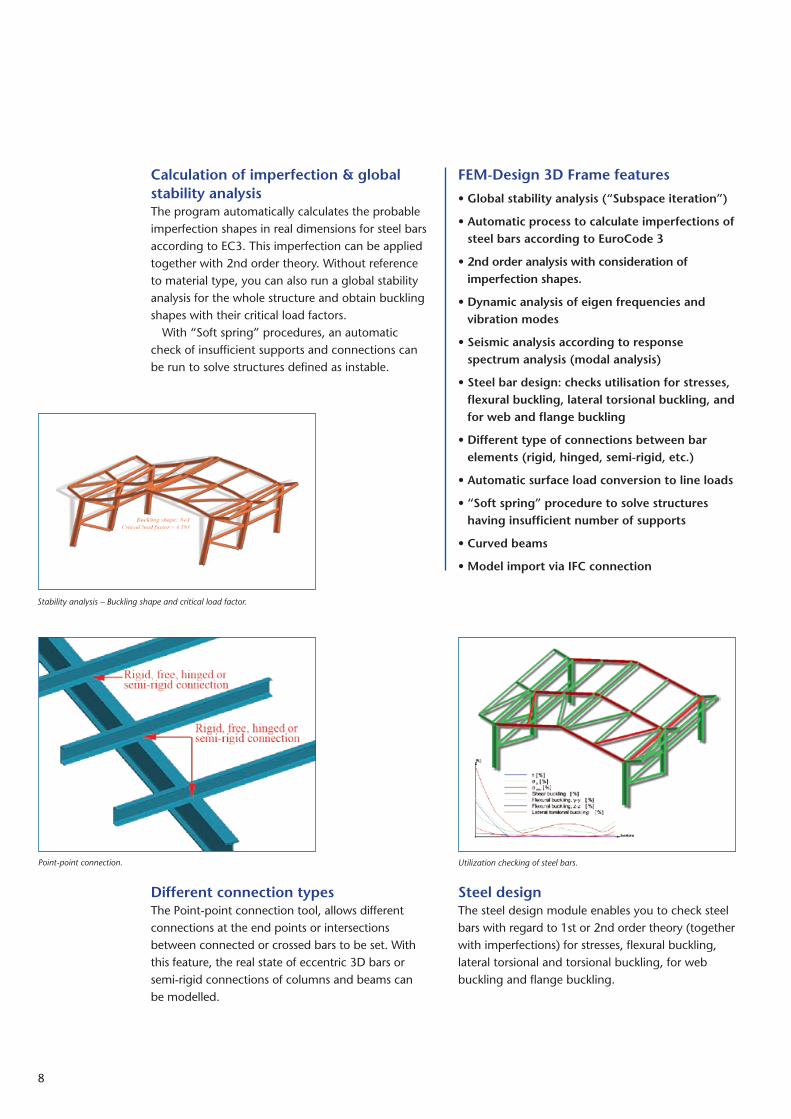
Steel designThe steel design module enables you to check steel bars with regard to 1st or �nd order theory (together with imperfections) for stresses, flexural buckling, lateral torsional and torsional buckling, for web buckling and flange buckling.
Different connection typesThe Point-point connection tool, allows different connections at the end points or intersections between connected or crossed bars to be set. With this feature, the real state of eccentric 3D bars or semi-rigid connections of columns and beams can be modelled.
Stability analysis – Buckling shape and critical load factor.
Point-point connection. Utilization checking of steel bars.

9
FEM-Design 3D Structure solves many construction problems containing mixtures of shell elements, slabs, walls, bars, beams and columns in arbitrary positions and loaded in any direction. Statical, dynamic, global stability, seismic analysis, concrete and/or steel design calculations can be run for the whole 3D-model.
The model geometry can be easily created in 3D with the help of several assistant tools such as axis and storey-systems, region operations, user-defined views and user-coordinate-systems. As before the user can also import DWG/DXF drawing files, 3D architectural or structural models and IFC model-based files.For slab, wall and roof region elements, FEM-Design works with a common shell finite element with six degrees of freedom for each node. Bars, beams and columns have bar elements also with six degrees of freedom for each node. This makes it possible to analyse composite structures. There is no limit on the number of finite elements, and the program automatically generates the finite element mesh with the most optimal element sizes with automatic refinements at the supports and element connections.
The calculation results can be shown graphically as graphs, contour lines, colour palettes in 3D for the whole structure, in �D by storeys (by slabs) or by vertical planes (by walls), or as arbitrarily placed sections by structural elements. Interesting numerical values can be shown in all images either by an auto-matic search and presentation for absolute values or
FEM-Design 3D Structure
local maximum and minimum values. In addition, the user can point with the mouse anywhere on the image to get a numeric result. To set the required views in 3D easily, dynamic zoom, pan and rotation commands are built into the program via powerful OpenGL technology.
As a special feature, solid definition and solid operation (union, substract, intersection etc.) tools can be used to create arbitrary shapes and positions of shell elements.
3D StructureNo limit no number of elements.
Result display modes by storeys

10
Design of precast concrete elementsEnhanced edge and line-line connection tools allow connections between structural region objects with different displacement components (rigid, free, hinged or arbitrary connection stiffness) to be defi-ned. For example, precast concrete elements can be easily modelled using shell elements.
Modelling and steel checking of vari-able bar cross-sectionsWithin the 3D Structure module, steel bars, beams and columns can also be analysed as shell elements, offering an accurate way of checking them for buckling (steel utilization). The “shell element” technology also allows the modelling of variable bar cross-sections, holes and stiffeners in webs, and sections built of different steel materials (non-homogenic steel sections).
Special load definitionsSeveral types of load can be defined in 3D structure, including (forces, moments, support displacement, stress and temperature loads). The program offers additional built-in features for loads: predefined load intensity values according to codes, fast algo-tithms to define surface loads, including varying intensity and automatic distribution of surface load onto bars (automatic conversion to line loads).
Solid drawing for special 3D models.
3D structure ModuleDesign forces, FE mesh & global stability
Special load directions & surface load conversion to line load.
Steel checking by shell theory – Variable bar cross-sections
11
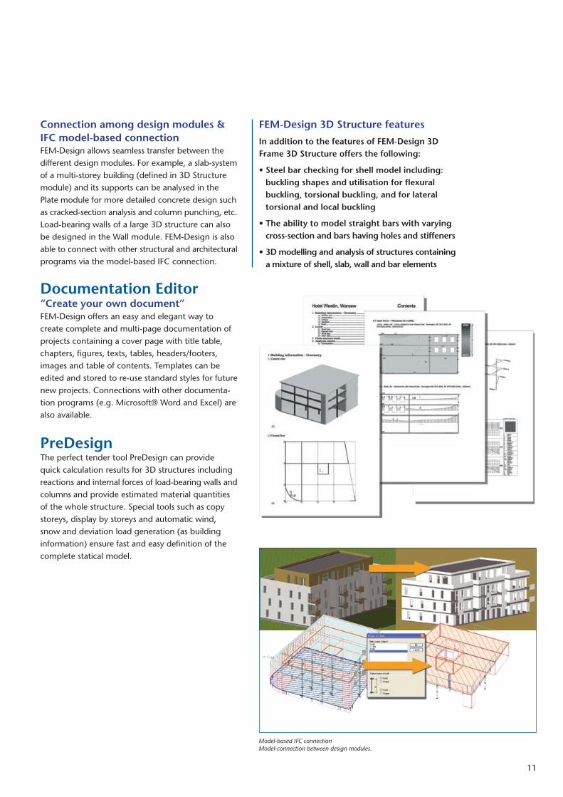
Connection among design modules & IFC model-based connectionFEM-Design allows seamless transfer between the different design modules. For example, a slab-system of a multi-storey building (defined in 3D Structure module) and its supports can be analysed in the Plate module for more detailed concrete design such as cracked-section analysis and column punching, etc. Load-bearing walls of a large 3D structure can also be designed in the Wall module. FEM-Design is also able to connect with other structural and architectural programs via the model-based IFC connection.
Documentation Editor“Create your own document”FEM-Design offers an easy and elegant way to create complete and multi-page documentation of projects containing a cover page with title table, chapters, figures, texts, tables, headers/footers, images and table of contents. Templates can be edited and stored to re-use standard styles for future new projects. Connections with other documenta-tion programs (e.g. Microsoft® Word and Excel) are also available.
PreDesignThe perfect tender tool PreDesign can provide quick calculation results for 3D structures including reactions and internal forces of load-bearing walls and columns and provide estimated material quantities of the whole structure. Special tools such as copy storeys, display by storeys and automatic wind, snow and deviation load generation (as building information) ensure fast and easy definition of the complete statical model.
FEM-Design 3D Structure features
In addition to the features of FEM-Design 3D Frame 3D Structure offers the following:
• Steel bar checking for shell model including: buckling shapes and utilisation for flexural buckling, torsional buckling, and for lateral torsional and local buckling
• The ability to model straight bars with varying cross-section and bars having holes and stiffeners
• 3D modelling and analysis of structures containing a mixture of shell, slab, wall and bar elements
Model-based IFC connection Model-connection between design modules.

www.strusoft.com, www.fem-design.com
IntegerInteger
NorconsultNorconsult
StruSoftStruSoft
StruSoftStruSoft
Nord EngineeringNord Engineering
ArutecArutec
StruSoftStruSoft
MódiStudióMódiStudióSPC ProjectSPC Project
ARUTEC OÜEstonia pst. 1/3
10143 Tallinn, Estonia
Phone: +372 630 6630
Fax: +372 630 6631
www.arutec.ee
IntegerThe Old Forge, South Road, Weybridge
KT13 9DZ Surrey, United Kingdom
Phone: +44 1932 858516
Fax: +44 1932 859099
www.integer-software.co.uk
MódiStudió Kft.Nagymezô utca 58
1065 Budapest, Hungary
Phone & Fax: +36 1 269 2525
www.modistudio.hu
NorconsultInformasjonssystemer ASVestfjordgaten 4
1338 Sandvika, Norway
Phone: +47 67 57 15 00
Fax: +47 67 54 45 76
[email protected], www.nois.no
Nord Engineering OYEerikinkatu 7
20100 Turku, Finland
Phone: +358 2 25 13 322
Fax: +358 2 25 02 642
SPC ProjectStudio Ingegneria PedroccoVia Venezia 4
35020 Albinasego (PD), Italy
Phone & Fax: +39 49 712 441
www.spcproject.it
StruSoft ABFridhemsvägen 22
217 74 Malmö, Sweden
Phone: +46 40 53 01 00
Fax: +46 40 53 01 05
www.strusoft.com
StruSoft ABFleminggatan 15
112 26 Stockholm, Sweden
Phone: +46 8 652 58 40
www.strusoft.com
StruSoft KftIrinyi József utca 4-20
1117 Budapest, Hungary
Phone: +36 1 225 6123
Fax: +36 1 203 8719
www.strusoft.hu