FEI Tecnai Osiris S/TEM - 4D LABS User Facilities · The FEI Tecnai Osiris S/TEM is a complex tool...
53
4D LABS, Simon Fraser University 8888 University Drive, Burnaby, B.C. V5A 1S6 E [email protected] T 778.782.8084 F 778.782.3765 W www.4dlabs.ca FEI Tecnai Osiris S/TEM Standard Operating Procedure Revision: 1.0 — Last Updated: June 17 2014, Revised by Xin Zhang Overview This document will provide a detailed operation procedure of the Tecnai Osiris S/TEM system. Formal Training is required for all users prior to using the system. Revision History # Revised by: Date Modification 1 2 3 4 5 Document No. 4DSOPTEM3
Transcript of FEI Tecnai Osiris S/TEM - 4D LABS User Facilities · The FEI Tecnai Osiris S/TEM is a complex tool...

4D LABS, Simon Fraser University 8888 University Drive, Burnaby, B.C. V5A 1S6
E [email protected] T 778.782.8084 F 778.782.3765 W www.4dlabs.ca
FEI Tecnai Osiris S/TEM
Standard Operating Procedure
Revision: 1.0 — Last Updated: June 17 2014, Revised by Xin Zhang
Overview
This document will provide a detailed operation procedure of the Tecnai Osiris S/TEM system.
Formal Training is required for all users prior to using the system.
Revision History
# Revised by: Date Modification
1
2
3
4
5
Document No. 4DSOPTEM3

2
4D LABS, Simon Fraser University 8888 University Drive, Burnaby, B.C. V5A 1S6
E [email protected] T 778.782.8084 F 778.782.3765 W www.4dlabs.ca
Table of Contents
Overview.................................................................................................................................................. 1
Revision History ........................................................................................................................................ 1
Table of Contents ..................................................................................................................................... 2
General Information ................................................................................................................................. 3
Operation ................................................................................................................................................ 4
1. Checklist before using the machine .................................................................................................. 4
2. (Optional) Logging in Windows as a different user ............................................................................ 5
3. Mounting your sample on a TEM specimen holder ............................................................................ 6
4. Loading a TEM specimen holder ....................................................................................................... 7
5. Preparation for imaging.................................................................................................................... 9
6. TEM alignment ............................................................................................................................... 11
7. Obtaining TEM images with TEM Imaging & Analysis (TIA) .............................................................. 15
8. Obtaining TEM images with DigitalMicrograph (DM) ....................................................................... 18
9. Scanning TEM (STEM) alignment and HAADF STEM imaging ........................................................... 21
10. Acquiring EDX spectra and mapping with TEM Imaging & Analysis (TIA) ....................................... 25
11. Acquiring EDX spectra and mapping with (Bruker) Esprit ............................................................... 30
12. Acquiring EELS spectra under TEM mode in DigitalMicrograph (DM) .............................................. 37
13. Acquiring EELS spectrum imaging (SI) – STEM/EELS ...................................................................... 42
14. Completing work ......................................................................................................................... 50
15. Unloading a TEM specimen holder ................................................................................................ 52
References and Files ............................................................................................................................... 53
Contact Information ............................................................................................................................... 53

3
4D LABS, Simon Fraser University 8888 University Drive, Burnaby, B.C. V5A 1S6
E [email protected] T 778.782.8084 F 778.782.3765 W www.4dlabs.ca
General Information
The FEI Tecnai Osiris is an analytical S/TEM system that is designed for high-resolution and high-
throughput elemental and structural analysis of a variety of materials. The key features of the system are:
X-FEG Schottky field emitter with high brightness, oil-free pumping system,
Analytical TWIN (A-TWIN) objective lens integrated with Super-X EDX detection system based on
Silicon Drift Detector (SDD) technology,
Gatan Ultrascan1000XP-P 2k X 2k CCD camera, HAADF, DF2, DF4, and BF STEM detectors, Gatan
Enfinium SE/976 EELS spectrometer
Fully digitized and "remote" operation to avoid vibration and temperature-variation induced by
the operator,
Fast STEM/EDX mapping (Esprit), S/TEM tomography (single tilt and dual-axis tomography holderS)
and 3-D reconstruction (Amira), EELS, STEM/PEELS,
High probe currents: 0.49 nA with 0.31 nm probe and 1.51 nA with 1 nm probe at 200 kV,
Flexible high tension: Pre-aligned at 80, 120, and 200 kV,
TEM point-resolution/resolution-limit: 0.25 nm/ 0.14 nm, STEM resolution: 0.16 nm, EELS energy
resolution: 0.9 V at optimal extractor voltage,
Beam drift: 0.89 nm/min, Specimen drift 0.42 nm/min
The FEI Tecnai Osiris S/TEM is a complex tool with various functions, some of which might not be useful to
every user. Therefore, not all the functions will be demonstrated during one scheduled training session.
Users qualified to work on the tool are unnecessarily qualified for all the functions. Users are NOT allowed
to try functions that have not been demonstrated. Osiris users need to schedule additional training ses-
sions to qualify for advanced tool functions.

4
4D LABS, Simon Fraser University 8888 University Drive, Burnaby, B.C. V5A 1S6
E [email protected] T 778.782.8084 F 778.782.3765 W www.4dlabs.ca
Operation
1. Checklist before using the machine
1. Log in your session on the logbook.
2. Vacuum status is good.
a. Gun pressure should be at 1 Log.
b. Column pressure should be mostly at 6 Log.
c. Camera pressure should be below 30 Log.
d. Cold trap LN2 (liquid nitrogen) should be more than 10%.
3. Column valves are closed. The Col. Valves Closed button appears yellow.
The Column Valves Closed status should also appear in the Flucam Viewer.
4. High Tension is activated at 200kV.
The High Tension button appears yellow.
5. FEG is operating at an extraction voltage of 3900V.
The Operate button appears yellow.
6. The system is not under Cryo Cycle.
a. A message will be displayed in front of the control computer if Cryo Cycle is being performed. And the Cold trap LN2 status will appear red.
b. If a Cyro Cycle is already finished, experienced users can fill up LN2 (liquid nitrogen) in the cold trap cool-ing dewar and use the machine. Allow sufficient cooling time (>1 hour) before working with EDX.
7. CompuStage/holder coordinates and tilts are at zero.
5
4D LABS, Simon Fraser University 8888 University Drive, Burnaby, B.C. V5A 1S6
E [email protected] T 778.782.8084 F 778.782.3765 W www.4dlabs.ca
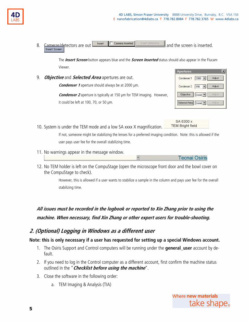
8. Cameras/detectors are out and the screen is inserted.
The Insert Screen button appears blue and the Screen Inserted status should also appear in the Flucam
Viewer.
9. Objective and Selected Area apertures are out.
Condenser 1 aperture should always be at 2000 µm.
Condenser 2 aperture is typically at 150 µm for TEM imaging. However,
it could be left at 100, 70, or 50 µm.
10. System is under the TEM mode and a low SA xxxx X magnification.
If not, someone might be stabilizing the lenses for a preferred imaging condition. Note: this is allowed if the
user pays user fee for the overall stabilizing time.
11. No warnings appear in the message window.
12. No TEM holder is left on the CompuStage (open the microscope front door and the bowl cover on the CompuStage to check).
However, this is allowed if a user wants to stabilize a sample in the column and pays user fee for the overall
stabilizing time.
All issues must be recorded in the logbook or reported to Xin Zhang prior to using the
machine. When necessary, find Xin Zhang or other expert users for trouble-shooting.
2. (Optional) Logging in Windows as a different user
Note: this is only necessary if a user has requested for setting up a special Windows account.
1. The Osiris Support and Control computers will be running under the general_user account by de-fault.
2. If you need to log in the Control computer as a different account, first confirm the machine status outlined in the “Checklist before using the machine”.
3. Close the software in the following order:
a. TEM Imaging & Analysis (TIA)

6
4D LABS, Simon Fraser University 8888 University Drive, Burnaby, B.C. V5A 1S6
E [email protected] T 778.782.8084 F 778.782.3765 W www.4dlabs.ca
b. Esprit
c. Gatan Digital Micrograph
When closing Gatan Digital Micrograph, click on the Exit
without saving button in the popup window.
d. Flucam Viewer
e. TEM User Interface
4. Log off the Windows and then log in the Windows with your own account and password (or gen-eral_user/osiris).
5. Start the software from the task bar in the following order:
Allow some waiting time between loading programs to avoid confusing the communication.
a. TEM User Interface
b. Flucam Viewer
c. Gatan Digital Micrograph
d. Esprit
Simply click on the login button when seeing the log in
(edx/***, Local server) window.
e. TEM Imaging & Analysis (TIA)
3. Mounting your sample on a TEM specimen holder
1. Inspect your sample under an optical microscope to ensure material is well attached to the TEM grid and also thin enough for TEM imaging. This is very important when depositing material from organic solutions, as thick organic residue could crack and produce fragile debris.
2. Ensure the sample is fully degassed. You can achieve this by putting the sample in a vacuum chamber for a few minutes.
3. Wear gloves when handling TEM specimen holders. Avoid touching anywhere from the O-ring to the tip of a holder.
4. Select an appropriate holder and inspect the holder tip under the optical microscope for any dirt. Use an air dust blower to remove dirt.

7
4D LABS, Simon Fraser University 8888 University Drive, Burnaby, B.C. V5A 1S6
E [email protected] T 778.782.8084 F 778.782.3765 W www.4dlabs.ca
5. Mount your TEM grid on the holder with the darker side down. Normally the material of interest is prepared on the darker side of a TEM grid.
6. Inspect the holder tip under the optical microscope to ensure the TEM grid is well positioned and locked.
7. Slowly rotate and meanwhile gently tap the holder to ensure the TEM grid is securely fixed.
8. Inspect the O-ring, use dry clean cloth or an air dust blower to remove any dirt.
Never use solvents such as isopropanol (IPA) to clean the holder!
9. (Recommended) Clean the sample and holder in the plasma cleaner (or a UV cleaner) for ease of imaging and better images, whenever applicable. (See User Manual for the Fischione M1020 Plasma Cleaner for the operation of the plasma cleaner)
a. Some soft materials might not be suitable for plasma cleaning.
b. Cleaning conditions should be carefully chosen and optimized.
4. Loading a TEM specimen holder
1. Keep the room door open when loading a TEM specimen holder.
Make sure the room door is securely locked at the open position so that it won’t surprisingly bump into you as
you are loading the TEM holder.
2. Open the microscope front door and take the bowl cover off the CompuStage.
Pin for lifting sample
clamp (stored in base)
Holder tip with a
sample clamp
Single-tilt specimen holder in a holder station/chamber
Pin
Clamp
Sample goes here.
8
4D LABS, Simon Fraser University 8888 University Drive, Burnaby, B.C. V5A 1S6
E [email protected] T 778.782.8084 F 778.782.3765 W www.4dlabs.ca
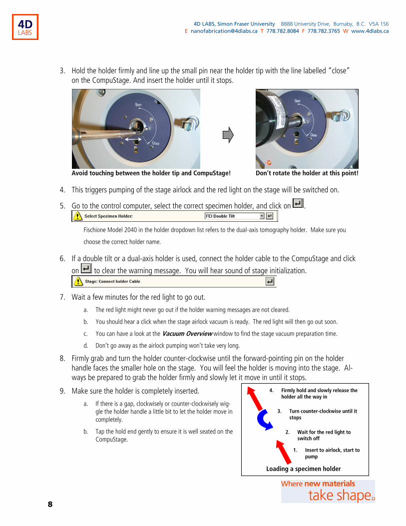
3. Hold the holder firmly and line up the small pin near the holder tip with the line labelled “close” on the CompuStage. And insert the holder until it stops.
Avoid touching between the holder tip and CompuStage! Don’t rotate the holder at this point!
4. This triggers pumping of the stage airlock and the red light on the stage will be switched on.
5. Go to the control computer, select the correct specimen holder, and click on .
Fischione Model 2040 in the holder dropdown list refers to the dual-axis tomography holder. Make sure you
choose the correct holder name.
6. If a double tilt or a dual-axis holder is used, connect the holder cable to the CompuStage and click
on to clear the warning message. You will hear sound of stage initialization.
7. Wait a few minutes for the red light to go out.
a. The red light might never go out if the holder warning messages are not cleared.
b. You should hear a click when the stage airlock vacuum is ready. The red light will then go out soon.
c. You can have a look at the Vacuum Overview window to find the stage vacuum preparation time.
d. Don’t go away as the airlock pumping won’t take very long.
8. Firmly grab and turn the holder counter-clockwise until the forward-pointing pin on the holder handle faces the smaller hole on the stage. You will feel the holder is moving into the stage. Al-ways be prepared to grab the holder firmly and slowly let it move in until it stops.
9. Make sure the holder is completely inserted.
a. If there is a gap, clockwisely or counter-clockwisely wig-gle the holder handle a little bit to let the holder move in completely.
b. Tap the hold end gently to ensure it is well seated on the CompuStage.
4. Firmly hold and slowly release the holder all the way in
3. Turn counter-clockwise until it stops
1. Insert to airlock, start to
pump
Loading a specimen holder
2. Wait for the red light to switch off
9
4D LABS, Simon Fraser University 8888 University Drive, Burnaby, B.C. V5A 1S6
E [email protected] T 778.782.8084 F 778.782.3765 W www.4dlabs.ca
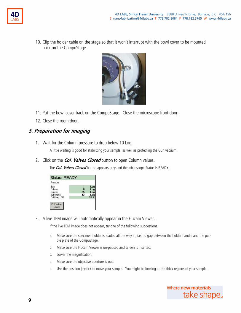
10. Clip the holder cable on the stage so that it won’t interrupt with the bowl cover to be mounted back on the CompuStage.
11. Put the bowl cover back on the CompuStage. Close the microscope front door.
12. Close the room door.
5. Preparation for imaging
1. Wait for the Column pressure to drop below 10 Log.
A little waiting is good for stabilizing your sample, as well as protecting the Gun vacuum.
2. Click on the Col. Valves Closed button to open Column values.
The Col. Valves Closed button appears grey and the microscope Status is READY.
3. A live TEM image will automatically appear in the Flucam Viewer.
If the live TEM image does not appear, try one of the following suggestions.
a. Make sure the specimen holder is loaded all the way in, i.e. no gap between the holder handle and the pur-
ple plate of the CompuStage.
b. Make sure the Flucam Viewer is un-paused and screen is inserted.
c. Lower the magnification.
d. Make sure the objective aperture is out.
e. Use the position joystick to move your sample. You might be looking at the thick regions of your sample.
10
4D LABS, Simon Fraser University 8888 University Drive, Burnaby, B.C. V5A 1S6
E [email protected] T 778.782.8084 F 778.782.3765 W www.4dlabs.ca
f. Use the Intensity knob to expand and condense the beam, if the beam is shifted use the beam trackball to bring it back.
g. When necessary, perform steps 4 and 5, and then try to get a live TEM image again.
4. Set up suitable Column conditions
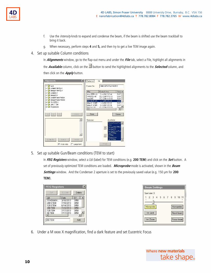
In Alignments window, go to the flap-out menu and under the File tab, select a File, highlight all alignments in
the Available column, click on the button to send the highlighted alignments to the Selected column, and
then click on the Apply button.
5. Set up suitable Gun/Beam conditions (TEM to start)
In FEG Registers window, select a Lbl (label) for TEM conditions (e.g. 200 TEM) and click on the Set button. A
set of previously optimized TEM conditions are loaded. Microprobe mode is activated, shown in the Beam
Settings window. And the Condenser 2 aperture is set to the previously saved value (e.g. 150 µm for 200
TEM).
6. Under a M xxxx X magnification, find a dark feature and set Eucentric Focus
11
4D LABS, Simon Fraser University 8888 University Drive, Burnaby, B.C. V5A 1S6
E [email protected] T 778.782.8084 F 778.782.3765 W www.4dlabs.ca
a. By pressing the Eucentric Focus button, the objective lens is focused on the eucentric plane (and mostly de-focus value is set zero or close to zero).
b. During imaging, defocus value should be maintained not too far away from zero, or within ± 2-3 µm.
c. Use the beam trackball to center the beam and use the Intensity knob to clock-wisely expand the beam to cover the screen. Click on the Int. Zoom button in the Beam Settings window.
d. This Int. Zoom will allow a “constant” beam area when you are changing magnification. However, this Int. Zoom will be automatically switched off when the magnification is too low (LM xxxx X or lower), or when the beam is too bright. It will be automatically switched on when the magnification and beam condi-tions permit.
7. Find the eucentric height for the sample
Method 1:
a. Activate Alpha Wobbler by either pressing the R2 button or clicking on the Wobbler button under Stage2 → ► flap-out → Control.
b. Press the z-axis buttons to minimize the image shift. Repeat at higher magnification until ≥ SA 10 kX. If the image shift is within 1 µm, it is pretty good.
c. De-activate Alpha Wobbler by either pressing the R2 button again or clicking on the Wobbler button under Stage2 → ► flap-out → Control again.
Method 2 (not ideal for holey carbon or single crystal samples):
a. Use the Intensity knob to condense the beam at an area of interest.
b. If the area of interest is not at the eucentric height, there will be a halo (or diffraction rings/spots) around the central bright spot. Click on the HDR (High-Dynamic-Range) button in the Flucam Viewer if the diffraction rings/spots are difficult to see.
c. Press the z-axis buttons to minimize the halo. Repeat at higher magnification until ≥ SA 10 kX.
d. Click on the High Contrast button in the Flucam Viewer to switch back to High Contrast Flucam Viewer imaging mode.
6. TEM alignment
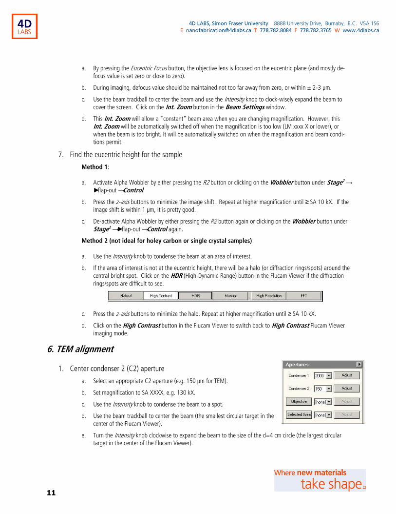
1. Center condenser 2 (C2) aperture
a. Select an appropriate C2 aperture (e.g. 150 µm for TEM).
b. Set magnification to SA XXXX, e.g. 130 kX.
c. Use the Intensity knob to condense the beam to a spot.
d. Use the beam trackball to center the beam (the smallest circular target in the center of the Flucam Viewer).
e. Turn the Intensity knob clockwise to expand the beam to the size of the d=4 cm circle (the largest circular target in the center of the Flucam Viewer).
12
4D LABS, Simon Fraser University 8888 University Drive, Burnaby, B.C. V5A 1S6
E [email protected] T 778.782.8084 F 778.782.3765 W www.4dlabs.ca
f. If the beam doesn’t meet the largest circle evenly, click on the Condenser 2 Adjust button in the Aper-tures window and use the Multifunction X and Multifunction Y knobs to make the expanded beam line up with the largest circle evenly.
g. Repeat steps c. to f. until the beam remains centered both in condensed and expanded forms.
h. Click on the Condenser 2 Adjust button again to reserve the current aperture position.
i. Avoid intensity crossover when centering C2 aperture. Otherwise the magnetic hysteresis makes you believe the condensed beam is always moving away from center.
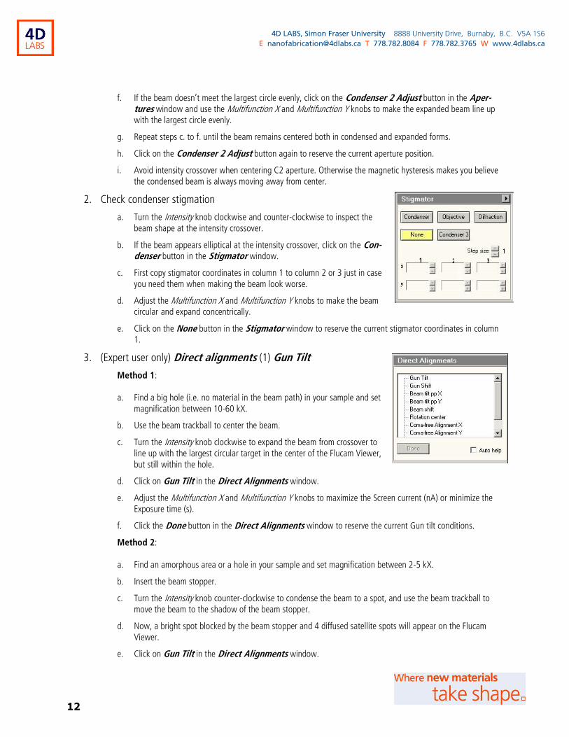
2. Check condenser stigmation
a. Turn the Intensity knob clockwise and counter-clockwise to inspect the beam shape at the intensity crossover.
b. If the beam appears elliptical at the intensity crossover, click on the Con-denser button in the Stigmator window.
c. First copy stigmator coordinates in column 1 to column 2 or 3 just in case you need them when making the beam look worse.
d. Adjust the Multifunction X and Multifunction Y knobs to make the beam circular and expand concentrically.
e. Click on the None button in the Stigmator window to reserve the current stigmator coordinates in column 1.
3. (Expert user only) Direct alignments (1) Gun Tilt
Method 1:
a. Find a big hole (i.e. no material in the beam path) in your sample and set magnification between 10-60 kX.
b. Use the beam trackball to center the beam.
c. Turn the Intensity knob clockwise to expand the beam from crossover to line up with the largest circular target in the center of the Flucam Viewer, but still within the hole.
d. Click on Gun Tilt in the Direct Alignments window.
e. Adjust the Multifunction X and Multifunction Y knobs to maximize the Screen current (nA) or minimize the Exposure time (s).
f. Click the Done button in the Direct Alignments window to reserve the current Gun tilt conditions.
Method 2:
a. Find an amorphous area or a hole in your sample and set magnification between 2-5 kX.
b. Insert the beam stopper.
c. Turn the Intensity knob counter-clockwise to condense the beam to a spot, and use the beam trackball to move the beam to the shadow of the beam stopper.
d. Now, a bright spot blocked by the beam stopper and 4 diffused satellite spots will appear on the Flucam Viewer.
e. Click on Gun Tilt in the Direct Alignments window.
1 2 3

13
4D LABS, Simon Fraser University 8888 University Drive, Burnaby, B.C. V5A 1S6
E [email protected] T 778.782.8084 F 778.782.3765 W www.4dlabs.ca
f. Adjust the Multifunction X and Multifunction Y knobs to make the bright spot coincident with the diagonal center of the 4 diffused satellite spots, and meanwhile use the beam trackball to keep the bright spot blocked by the beam stopper (otherwise, the 4 diffused satellite spots are invisible due to their low intensity).
g. Click the Done button in the Direct Alignments window to reserve the current Gun tilt conditions.
h. Turn the Intensity knob clockwise to expand the beam.
i. Withdraw the beam stopper.
4. (Expert user only) Direct alignments (2) Gun Shift
Method 1:
a. Set magnification between 10-60 kX.
b. Click on Gun Shift in the Direct Alignments window.
c. Set the Spot size to 9 in the Beam Settings window and use the Intensity knob to condense the beam to a spot.
d. Center the beam using the beam trackball. (Very important!)
e. Set the Spot size to 3 in the Beam Settings window and use the Intensity knob to condense the beam to a spot.
f. Center the beam using the Multifunction X and Multifunction Y knobs. (Very important!)
g. Repeat steps c. to f. until the beam is centered for both spot size 3 and 9, and leave the spot size at 3. (It is OK if the beam is slightly away from the center for other spot sizes.)
h. Click the Done button in the Direct Alignments window to reserve the current Gun shift conditions.
Method 2:
a. Set magnification to 225 kX or higher and set the Spot size to 3 in the Beam Settings window.
b. Turn the Intensity knob clockwise to expand the beam from a spot to a 1~2 cm circle (line up with the medi-um circular target on the Flucam Viewer), enough to see the brightest region in the beam.
c. Click on Gun Shift in the Direct Alignments window.
d. Adjust the Multifunction X and Multifunction Y knobs to center the beam.
e. Use the beam track ball to center the brightest region in the beam.
f. Repeat steps d. to e. until the brightest region is at the center of the beam and the beam is also centered.
g. Click the Done button in the Direct Alignments window to reserve the current Gun shift conditions.
Method 3:
a. Set magnification to 225 kX or higher.
b. Set the Spot size to 3 in the Beam Settings window and turn the Intensity knob counter-clockwise to condense the beam to a spot.
c. Click on Gun Shift in the Direct Alignments window. Adjust the Multifunction X and Multifunction Y knobs to center the beam.
d. Click the Done button in the Direct Alignments window to reserve the current Gun shift conditions.

14
4D LABS, Simon Fraser University 8888 University Drive, Burnaby, B.C. V5A 1S6
E [email protected] T 778.782.8084 F 778.782.3765 W www.4dlabs.ca
e. Set the Spot size to 9 in the Beam Settings window and turn the Intensity knob counter-clockwise to condense the beam to a spot.
f. Click on Beam shift in the Direct Alignments window. Adjust the Multifunction X and Multifunction Y knobs to center the beam.
g. Click the Done button in the Direct Alignments window to reserve the current Beam shift conditions.
h. Repeat steps b. to g. until the beam is centered for both spot size 3 and 9, and leave at spot size at 3.
5. It may be necessary to center C2 aperture and check condenser stigmation again if Gun tilt and Gun shift alignments were performed.
6. Direct alignments (3) Beam tilt pp X and Beam tilt pp Y
a. Set magnification to SA XXXX, e.g. 130 kX or higher.
b. Turn the Intensity knob counter-clockwise to condense the beam to a 1~2 cm circle (line up with the medi-um circular target on the Flucam Viewer) or to a spot depending on user preference, and use the beam trackball to center the beam.
c. Click on Beam tilt pp X in the Direct Alignments window to wobble the beam.
d. Adjust the Multifunction X and Multifunction Y knobs to minimize the beam movement.
e. If the beam is moved out of view, reduce the magnification and use the beam trackball to bring the beam back in view. Bring the magnification back up to 130 kX or higher, and repeat step d.
f. Click on the Done button in the Direct Alignments window to reserve the current Beam tilt pp X condi-tions.
g. Repeat steps a. to f. for Beam tilt pp Y in the Direct Alignments window.
7. Direct alignments (4) Beam shift
a. This alignment is needed if the beam has a huge displacement when changing magnification or when acti-vating the Rotation center alignment.
b. Set magnification to SA XXXX, e.g. 130 kX or higher.
c. Turn the Intensity knob counter-clockwise to condense the beam to a spot.
d. Click on Beam shift in the Direct Alignments window to reset the temporary beam shift by the beam trackball.
e. If the beam is out of view, reduce the magnification.
f. Adjust the Multifunction X and Multifunction Y knobs to center the beam.
g. Bring the magnification back up to 130 kX or higher, and repeat step e.
h. Click on the Done button in the Direct Alignments window to reserve the current Beam shift conditions.
8. Focus on a feature
a. Find a feature on your sample and focus to minimum contrast using the focus knob.
b. If the defocus value is beyond ± 2-3 µm, press the Eucentric Focus button to focus the objective lens on the eucentric plane, and press the z-axis buttons to bring the feature to focus.
9. Direct alignments (5) Rotation center
15
4D LABS, Simon Fraser University 8888 University Drive, Burnaby, B.C. V5A 1S6
E [email protected] T 778.782.8084 F 778.782.3765 W www.4dlabs.ca
a. Set magnification to SA XXXX, e.g. 130 kX or higher.
b. Turn the Intensity knob clockwise to fully expand the beam to cover the screen.
c. Use the position joystick to bring the focused feature to the center.
d. Click on Rotation center in the Direct Alignments window to wobble the beam.
e. Adjust the Multifunction X and Multifunction Y knobs to minimize the image shift (i.e. minimal lateral movement), using the focused feature for visualization of the image shift under the wobbling beam.
f. Click on the Done button in the Direct Alignments window to reserve the current Rotation center con-ditions.
g. This alignment is very important for high resolution TEM, and also very sensitive to the Beam tilt pp X, Beam tilt pp Y, beam centering, and sample height. Therefore, it may be necessary to repeat steps 6. to 9.
when imaging different locations of a sample.
7. Obtaining TEM images with TEM Imaging & Analysis (TIA)
The CCD camera is very sensitive to beam intensity and could be burnt by an intense
beam. Therefore, do not change magnification or intensity under camera viewing mode.
Never use the camera to image a condensed beam.
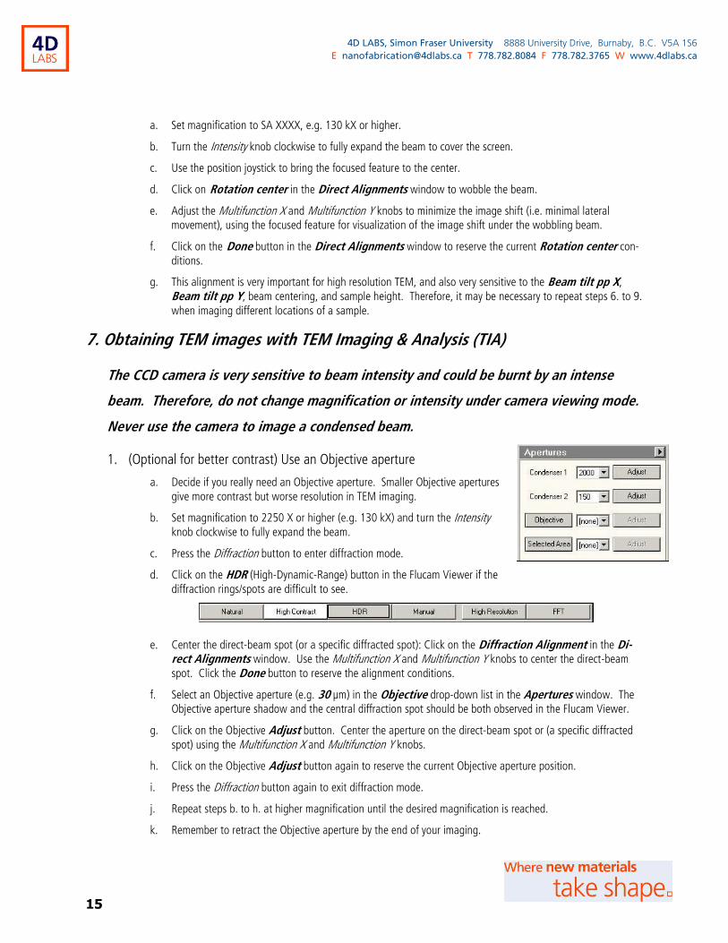
1. (Optional for better contrast) Use an Objective aperture
a. Decide if you really need an Objective aperture. Smaller Objective apertures give more contrast but worse resolution in TEM imaging.
b. Set magnification to 2250 X or higher (e.g. 130 kX) and turn the Intensity knob clockwise to fully expand the beam.
c. Press the Diffraction button to enter diffraction mode.
d. Click on the HDR (High-Dynamic-Range) button in the Flucam Viewer if the diffraction rings/spots are difficult to see.
e. Center the direct-beam spot (or a specific diffracted spot): Click on the Diffraction Alignment in the Di-rect Alignments window. Use the Multifunction X and Multifunction Y knobs to center the direct-beam spot. Click the Done button to reserve the alignment conditions.
f. Select an Objective aperture (e.g. 30 µm) in the Objective drop-down list in the Apertures window. The Objective aperture shadow and the central diffraction spot should be both observed in the Flucam Viewer.
g. Click on the Objective Adjust button. Center the aperture on the direct-beam spot or (a specific diffracted spot) using the Multifunction X and Multifunction Y knobs.
h. Click on the Objective Adjust button again to reserve the current Objective aperture position.
i. Press the Diffraction button again to exit diffraction mode.
j. Repeat steps b. to h. at higher magnification until the desired magnification is reached.
k. Remember to retract the Objective aperture by the end of your imaging.
16
4D LABS, Simon Fraser University 8888 University Drive, Burnaby, B.C. V5A 1S6
E [email protected] T 778.782.8084 F 778.782.3765 W www.4dlabs.ca
2. Find an area of interest, set a suitable magnification, and use the beam trackball to center the beam.
3. Turn the Intensity knob clockwise to expand the beam until the Exposure time is 2 seconds or longer.
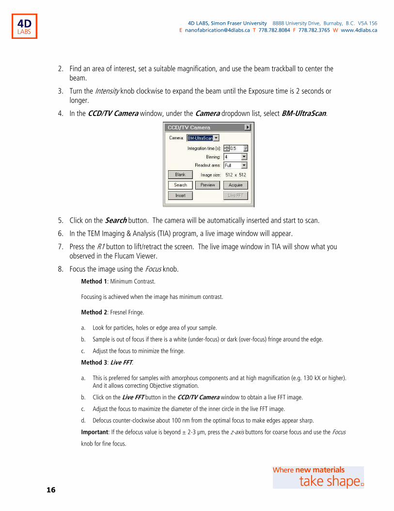
4. In the CCD/TV Camera window, under the Camera dropdown list, select BM-UltraScan.
5. Click on the Search button. The camera will be automatically inserted and start to scan.
6. In the TEM Imaging & Analysis (TIA) program, a live image window will appear.
7. Press the R1 button to lift/retract the screen. The live image window in TIA will show what you observed in the Flucam Viewer.
8. Focus the image using the Focus knob.
Method 1: Minimum Contrast.
Focusing is achieved when the image has minimum contrast.
Method 2: Fresnel Fringe.
a. Look for particles, holes or edge area of your sample.
b. Sample is out of focus if there is a white (under-focus) or dark (over-focus) fringe around the edge.
c. Adjust the focus to minimize the fringe.
Method 3: Live FFT.
a. This is preferred for samples with amorphous components and at high magnification (e.g. 130 kX or higher). And it allows correcting Objective stigmation.
b. Click on the Live FFT button in the CCD/TV Camera window to obtain a live FFT image.
c. Adjust the focus to maximize the diameter of the inner circle in the live FFT image.
d. Defocus counter-clockwise about 100 nm from the optimal focus to make edges appear sharp.
Important: If the defocus value is beyond ± 2-3 µm, press the z-axis buttons for coarse focus and use the Focus
knob for fine focus.
17
4D LABS, Simon Fraser University 8888 University Drive, Burnaby, B.C. V5A 1S6
E [email protected] T 778.782.8084 F 778.782.3765 W www.4dlabs.ca
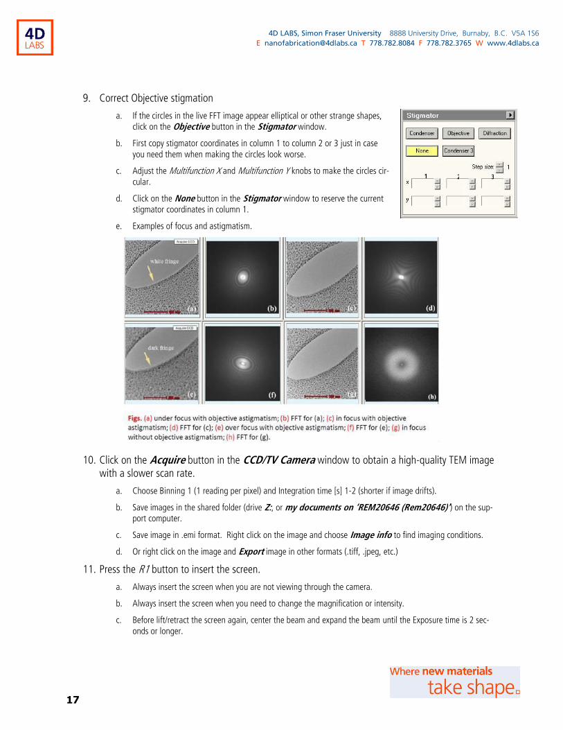
9. Correct Objective stigmation
a. If the circles in the live FFT image appear elliptical or other strange shapes, click on the Objective button in the Stigmator window.
b. First copy stigmator coordinates in column 1 to column 2 or 3 just in case you need them when making the circles look worse.
c. Adjust the Multifunction X and Multifunction Y knobs to make the circles cir-cular.
d. Click on the None button in the Stigmator window to reserve the current stigmator coordinates in column 1.
e. Examples of focus and astigmatism.
10. Click on the Acquire button in the CCD/TV Camera window to obtain a high-quality TEM image with a slower scan rate.
a. Choose Binning 1 (1 reading per pixel) and Integration time [s] 1-2 (shorter if image drifts).
b. Save images in the shared folder (drive Z:, or my documents on ‘REM20646 (Rem20646)’) on the sup-port computer.
c. Save image in .emi format. Right click on the image and choose Image info to find imaging conditions.
d. Or right click on the image and Export image in other formats (.tiff, .jpeg, etc.)
11. Press the R1 button to insert the screen.
a. Always insert the screen when you are not viewing through the camera.
b. Always insert the screen when you need to change the magnification or intensity.
c. Before lift/retract the screen again, center the beam and expand the beam until the Exposure time is 2 sec-onds or longer.
1 2 3
18
4D LABS, Simon Fraser University 8888 University Drive, Burnaby, B.C. V5A 1S6
E [email protected] T 778.782.8084 F 778.782.3765 W www.4dlabs.ca
12. Click on the Insert button in the CCD/TV Camera window to withdraw the camera.
a. The Insert button changes from yellow to grey.
b. Always withdraw the camera if you stop using it.
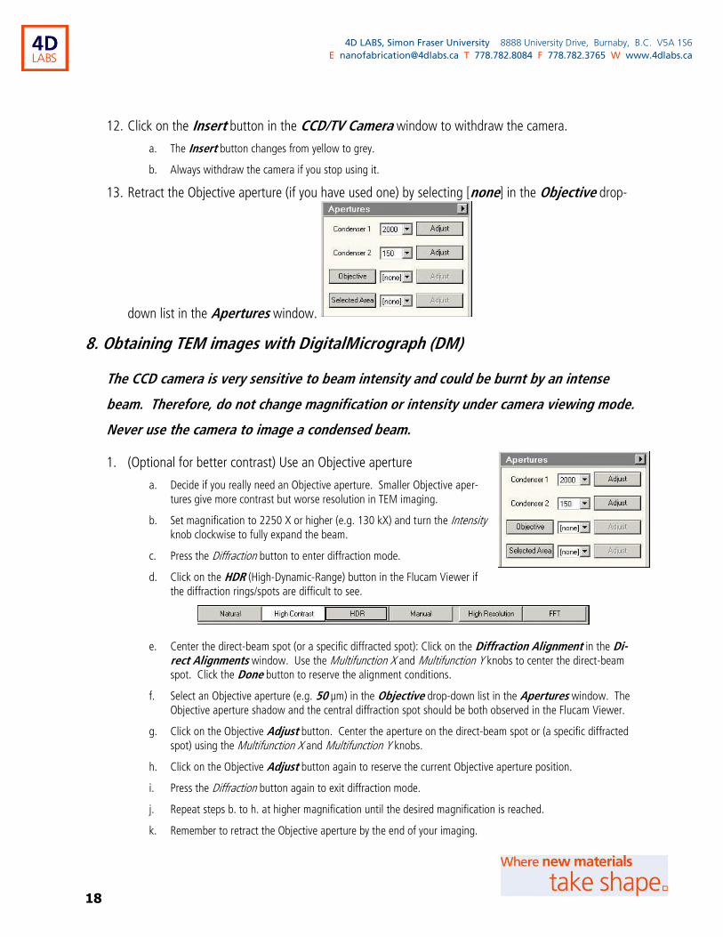
13. Retract the Objective aperture (if you have used one) by selecting [none] in the Objective drop-
down list in the Apertures window.
8. Obtaining TEM images with DigitalMicrograph (DM)
The CCD camera is very sensitive to beam intensity and could be burnt by an intense
beam. Therefore, do not change magnification or intensity under camera viewing mode.
Never use the camera to image a condensed beam.
1. (Optional for better contrast) Use an Objective aperture
a. Decide if you really need an Objective aperture. Smaller Objective aper-tures give more contrast but worse resolution in TEM imaging.
b. Set magnification to 2250 X or higher (e.g. 130 kX) and turn the Intensity knob clockwise to fully expand the beam.
c. Press the Diffraction button to enter diffraction mode.
d. Click on the HDR (High-Dynamic-Range) button in the Flucam Viewer if the diffraction rings/spots are difficult to see.
e. Center the direct-beam spot (or a specific diffracted spot): Click on the Diffraction Alignment in the Di-rect Alignments window. Use the Multifunction X and Multifunction Y knobs to center the direct-beam spot. Click the Done button to reserve the alignment conditions.
f. Select an Objective aperture (e.g. 50 µm) in the Objective drop-down list in the Apertures window. The Objective aperture shadow and the central diffraction spot should be both observed in the Flucam Viewer.
g. Click on the Objective Adjust button. Center the aperture on the direct-beam spot or (a specific diffracted spot) using the Multifunction X and Multifunction Y knobs.
h. Click on the Objective Adjust button again to reserve the current Objective aperture position.
i. Press the Diffraction button again to exit diffraction mode.
j. Repeat steps b. to h. at higher magnification until the desired magnification is reached.
k. Remember to retract the Objective aperture by the end of your imaging.

19
4D LABS, Simon Fraser University 8888 University Drive, Burnaby, B.C. V5A 1S6
E [email protected] T 778.782.8084 F 778.782.3765 W www.4dlabs.ca
2. Find an area of interest, set a suitable magnification, and use the beam trackball to center the beam.
3. Turn the Intensity knob clockwise to expand the beam until the Exposure time is 2 seconds or longer.
4. In the DigitalMicrograph (DM) program, select Camera > Camera ►BM-UltraScan.
5. Click on the Start View button in the Camera View window of DM.
a. A window will pop up for confirming the insertion of camera.
b. Click on the OK button.
c. The camera will be inserted and start to scan.
d. A live image window will appear in DM.
e. Click on the Stop View button in the Camera View window will freeze the live image, but camera remains inserted.
6. Press the R1 button to lift/retract the screen. The live image window in DM will show what you observed in the Flucam Viewer.
7. Focus the image using the Focus knob.
Method 1: Minimum Contrast.
Focusing is achieved when the image has minimum contrast.
Method 2: Fresnel Fringe.
a. Look for particles, holes or edge area of your sample.
b. Sample is out of focus if there is a white (under-focus) or dark (over-focus) fringe around the edge.
c. Adjust the focus to minimize the fringe.
Method 3: Live FFT.
a. This is preferred for samples with amorphous components and at high magnification (e.g. 130 kX or higher). And it allows correcting Objective stigmation.
b. In the DM program, select Process > Live ► FFT to ob-tain a live FFT image.
c. Adjust the focus to maximize the diameter of the inner circle in the live FFT image.
20
4D LABS, Simon Fraser University 8888 University Drive, Burnaby, B.C. V5A 1S6
E [email protected] T 778.782.8084 F 778.782.3765 W www.4dlabs.ca
d. Defocus counter-clockwise about 100 nm from the optimal focus to make edges appear sharp.
Important: If the defocus value is beyond ± 2-3 µm, press the z-axis buttons for coarse focus and use the Focus
knob for fine focus.
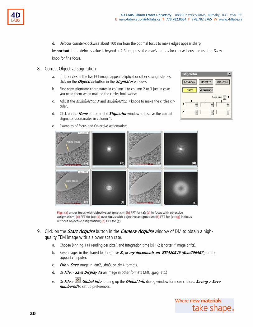
8. Correct Objective stigmation
a. If the circles in the live FFT image appear elliptical or other strange shapes, click on the Objective button in the Stigmator window.
b. First copy stigmator coordinates in column 1 to column 2 or 3 just in case you need them when making the circles look worse.
c. Adjust the Multifunction X and Multifunction Y knobs to make the circles cir-
cular.
d. Click on the None button in the Stigmator window to reserve the current stigmator coordinates in column 1.
e. Examples of focus and Objective astigmatism.
9. Click on the Start Acquire button in the Camera Acquire window of DM to obtain a high-quality TEM image with a slower scan rate.
a. Choose Binning 1 (1 reading per pixel) and Integration time [s] 1-2 (shorter if image drifts).
b. Save images in the shared folder ((drive Z:, or my documents on ‘REM20646 (Rem20646)’)) on the support computer.
c. File > Save image in .dm2, .dm3, or .dm4 formats.
d. Or File > Save Display As an image in other formats (.tiff, .jpeg, etc.)
e. Or File > Global Info to bring up the Global Info dialog window for more choices. Saving > Save numbered to set up preferences.
1 2 3
21
4D LABS, Simon Fraser University 8888 University Drive, Burnaby, B.C. V5A 1S6
E [email protected] T 778.782.8084 F 778.782.3765 W www.4dlabs.ca
10. Press the R1 button to insert the screen.
a. Always insert the screen when you are not viewing through the camera.
b. Always insert the screen when you need to change the magnification or intensity.
c. Before lift/retract the screen again, center the beam and expand the beam until the Exposure time is 2 sec-onds or longer.
11. Click on the Stop View button in the Camera View window of DM to freeze the live image.
12. Uncheck Camera Inserted ( ) in the Camera View window to withdraw the cam-era.
a. Always withdraw the camera if you stop using it.
b. Camera might be automatically withdrawn when idle for certain time, and as a result the Camera Inserted might appear as unchecked.
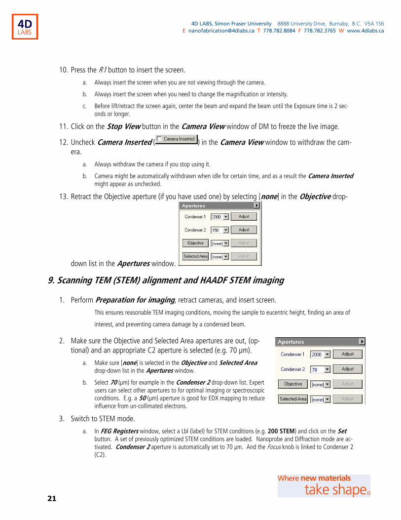
13. Retract the Objective aperture (if you have used one) by selecting [none] in the Objective drop-
down list in the Apertures window.
9. Scanning TEM (STEM) alignment and HAADF STEM imaging
1. Perform Preparation for imaging, retract cameras, and insert screen.
This ensures reasonable TEM imaging conditions, moving the sample to eucentric height, finding an area of
interest, and preventing camera damage by a condensed beam.
2. Make sure the Objective and Selected Area apertures are out, (op-tional) and an appropriate C2 aperture is selected (e.g. 70 µm).
a. Make sure [none] is selected in the Objective and Selected Area drop-down list in the Apertures window.
b. Select 70 (µm) for example in the Condenser 2 drop-down list. Expert users can select other apertures to for optimal imaging or spectroscopic conditions. E.g. a 50 (µm) aperture is good for EDX mapping to reduce influence from un-collimated electrons.
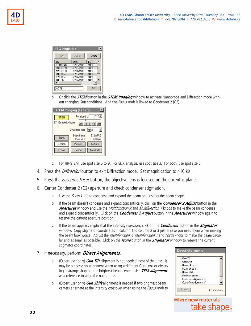
3. Switch to STEM mode.
a. In FEG Registers window, select a Lbl (label) for STEM conditions (e.g. 200 STEM) and click on the Set button. A set of previously optimized STEM conditions are loaded. Nanoprobe and Diffraction mode are ac-tivated. Condenser 2 aperture is automatically set to 70 µm. And the Focus knob is linked to Condenser 2 (C2).
70
22
4D LABS, Simon Fraser University 8888 University Drive, Burnaby, B.C. V5A 1S6
E [email protected] T 778.782.8084 F 778.782.3765 W www.4dlabs.ca
b. Or click the STEM button in the STEM Imaging window to activate Nanoprobe and Diffraction mode with-out changing Gun conditions. And the Focus knob is linked to Condenser 2 (C2).
c. For HR-STEM, use spot size 6 to 9. For EDX analysis, use spot size 3. For both, use spot size 6.
4. Press the Diffraction button to exit Diffraction mode. Set magnification to 410 kX.
5. Press the Eucentric Focus button, the objective lens is focused on the eucentric plane.
6. Center Condenser 2 (C2) aperture and check condenser stigmation.
a. Use the Focus knob to condense and expand the beam and inspect the beam shape.
b. If the beam doesn’t condense and expand concentrically, click on the Condenser 2 Adjust button in the Apertures window and use the Multifunction X and Multifunction Y knobs to make the beam condense and expand concentrically. Click on the Condenser 2 Adjust button in the Apertures window again to reserve the current aperture position.
c. If the beam appears elliptical at the intensity crossover, click on the Condenser button in the Stigmator window. Copy stigmator coordinates in column 1 to column 2 or 3 just in case you need them when making the beam look worse. Adjust the Multifunction X, Multifunction Y and Focus knobs to make the beam circu-lar and as small as possible. Click on the None button in the Stigmator window to reserve the current stigmator coordinates.
7. If necessary, perform Direct Alignments.
a. (Expert user only) Gun Tilt alignment is not needed most of the time. It may be a necessary alignment when using a different Gun Lens or observ-ing a strange shape of the brightest beam center. Use TEM alignment as a reference to align the nanoprobe.
b. (Expert user only) Gun Shift alignment is needed if two brightest beam centers alternate at the intensity crossover when using the Focus knob to
23
4D LABS, Simon Fraser University 8888 University Drive, Burnaby, B.C. V5A 1S6
E [email protected] T 778.782.8084 F 778.782.3765 W www.4dlabs.ca
condense and expand the beam. Use TEM alignment as a reference to align the nanoprobe.
c. Beam tilt pp X and Beam tilt pp Y alignments. Use the Focus knob to condense the beam to a spot. Ac-tivate Beam tilt pivot point alignments in the Direct Alignments window. Use the Multifunction X and Multifunction Y knobs to minimize the lateral beam movement. Use the beam trackball to bring back to center. Click the Done button to reserve the alignment conditions.
d. Beam shift alignment. Click on Beam shift in the Direct Alignments window. If the beam is lost, lower the magnification. Use the Multifunction X and Multifunction Y knobs to bring the beam back to center. Repeat for higher magnification until 410 kX. Click the Done button to reserve the alignment conditions.
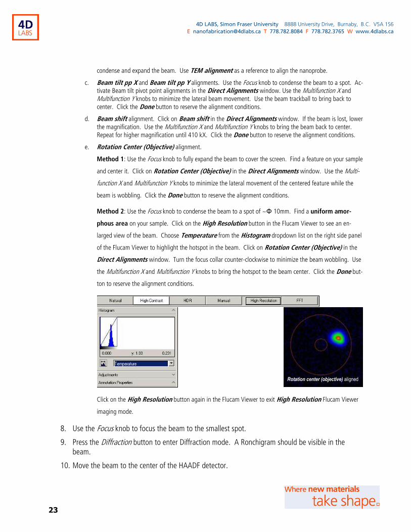
e. Rotation Center (Objective) alignment.
Method 1: Use the Focus knob to fully expand the beam to cover the screen. Find a feature on your sample
and center it. Click on Rotation Center (Objective) in the Direct Alignments window. Use the Multi-
function X and Multifunction Y knobs to minimize the lateral movement of the centered feature while the
beam is wobbling. Click the Done button to reserve the alignment conditions.
Method 2: Use the Focus knob to condense the beam to a spot of ~Φ 10mm. Find a uniform amor-
phous area on your sample. Click on the High Resolution button in the Flucam Viewer to see an en-
larged view of the beam. Choose Temperature from the Histogram dropdown list on the right side panel
of the Flucam Viewer to highlight the hotspot in the beam. Click on Rotation Center (Objective) in the
Direct Alignments window. Turn the focus collar counter-clockwise to minimize the beam wobbling. Use
the Multifunction X and Multifunction Y knobs to bring the hotspot to the beam center. Click the Done but-
ton to reserve the alignment conditions.
Click on the High Resolution button again in the Flucam Viewer to exit High Resolution Flucam Viewer
imaging mode.
8. Use the Focus knob to focus the beam to the smallest spot.
9. Press the Diffraction button to enter Diffraction mode. A Ronchigram should be visible in the beam.
10. Move the beam to the center of the HAADF detector.
Rotation center (objective) aligned
24
4D LABS, Simon Fraser University 8888 University Drive, Burnaby, B.C. V5A 1S6
E [email protected] T 778.782.8084 F 778.782.3765 W www.4dlabs.ca
a. Click on the Diffraction alignment in the Direct Alignments window.
b. Click on the HAADF Detector Area button (the largest green dot here ) in the Flu-cam Viewer to display the HAADF detector guiding circles in the Flucam window.
c. Use the Multifunction X and Multifunction Y knobs to move the beam to the center of the HAADF detector.
d. Click the Done button to reserve the alignment conditions.
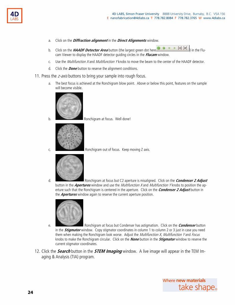
11. Press the z-axis buttons to bring your sample into rough focus.
a. The best focus is achieved at the Ronchigram blow point. Above or below this point, features on the sample will become visible.
b. Ronchigram at focus. Well done!
c. Ronchigram out of focus. Keep moving Z axis.
d. Ronchigram at focus but C2 aperture is misaligned. Click on the Condenser 2 Adjust button in the Apertures window and use the Multifunction X and Multifunction Y knobs to position the ap-erture such that the Ronchigram is centered in the aperture. Click on the Condenser 2 Adjust button in the Apertures window again to reserve the current aperture position.
e. Ronchigram at focus but Condenser has astigmatism. Click on the Condenser button in the Stigmator window. Copy stigmator coordinates in column 1 to column 2 or 3 just in case you need
them when making the Ronchigram look worse. Adjust the Multifunction X, Multifunction Y and Focus knobs to make the Ronchigram circular. Click on the None button in the Stigmator window to reserve the current stigmator coordinates.
12. Click the Search button in the STEM Imaging window. A live image will appear in the TEM Im-aging & Analysis (TIA) program.

25
4D LABS, Simon Fraser University 8888 University Drive, Burnaby, B.C. V5A 1S6
E [email protected] T 778.782.8084 F 778.782.3765 W www.4dlabs.ca
a. If there is no imaging in TIA, check if the Camera length is set to 220 mm. Image brightness or contrast might need adjustment as well. Click on the Auto C/B button in the STEM imaging window for automatic contrast and brightness adjustment.
b. For better image quality, the Camera length could be changed depending on the sample.
c. Still press the z-axis buttons to bring your sample close to the optimal focus.
13. Use the Focus knob to achieve fine focus.
a. Lower the magnification if focus is difficult due to astigmatism or sample drifting.
b. It may be still necessary to further adjust the Condenser stigmation with the live image.
14. Click on the Acquire button in the STEM Imaging window to obtain a high-quality HAADF STEM image with a slower scan rate.
a. Save images in the shared folder (drive Z:, or my documents on ‘REM20646 (Rem20646)’) on the sup-port computer.
b. Save image in .emi format. Right click on the image and choose Image info to find imaging conditions.
c. Or right click on the image and Export image in other formats (.tiff, .jpeg, etc.)
15. Once done with STEM imaging, click on the STEM button in the STEM Imaging window to exit the STEM and nanoprobe mode.
a. The machine switches to the TEM and microprobe mode.
b. This will also retract the HAADF detector.
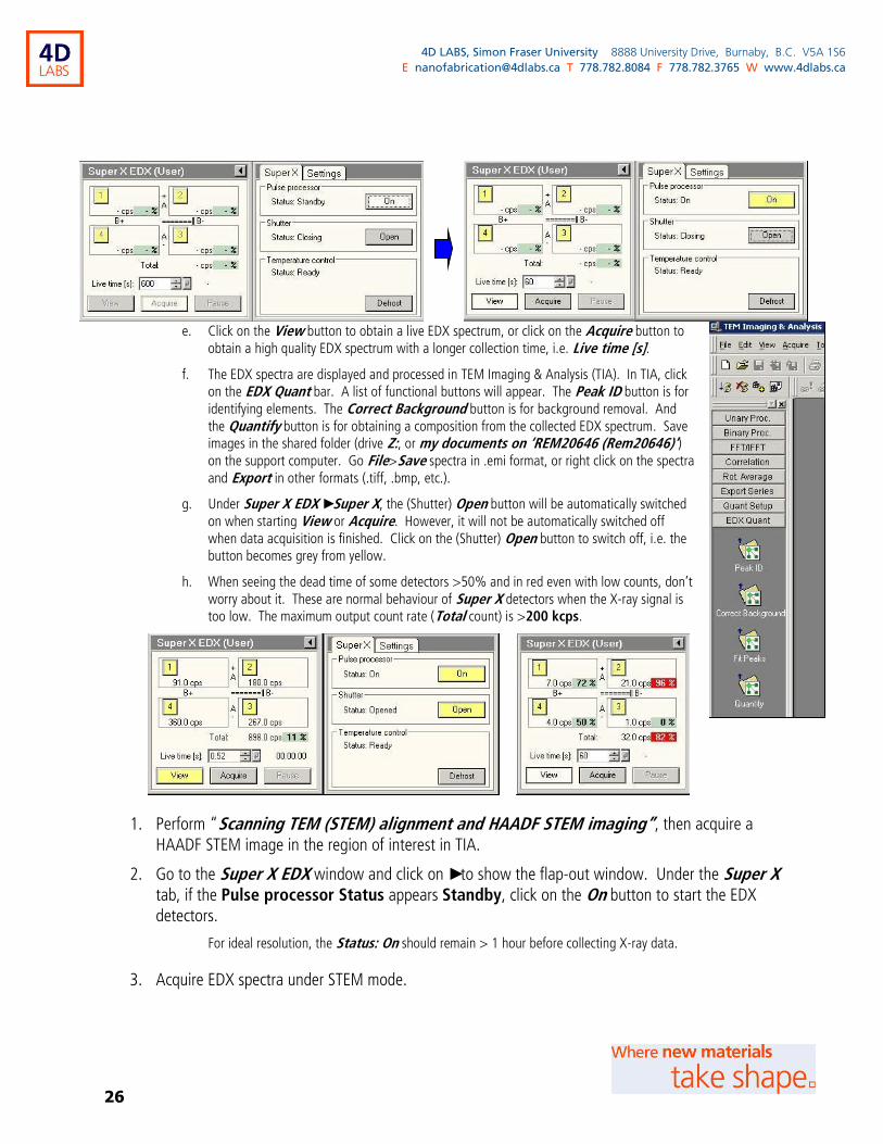
10. Acquiring EDX spectra and mapping with TEM Imaging & Analysis (TIA)
(Optional) Acquire EDX spectra under TEM mode.
a. You don’t have to use STEM mode to get compositional information of your sample, if you don’t need EDX mapping results and the resolution is not a concern. However, put in mind that the EDX spectra obtained under TEM mode contain contribution from more spurious X-rays.
b. Make sure the Objective and Selected Area apertures are out.
c. Condense the beam under TEM mode on a region of interest, either a spot or an area.
d. Go to the Super X EDX window and click on ► to show the flap-out window. Under the Super X tab, if the Pulse processor Status appears Standby, click on the On button to start the EDX detectors. For ide-al resolution, the Status: On should remain > 1 hour before collecting X-ray data.
26
4D LABS, Simon Fraser University 8888 University Drive, Burnaby, B.C. V5A 1S6
E [email protected] T 778.782.8084 F 778.782.3765 W www.4dlabs.ca
e. Click on the View button to obtain a live EDX spectrum, or click on the Acquire button to obtain a high quality EDX spectrum with a longer collection time, i.e. Live time [s].
f. The EDX spectra are displayed and processed in TEM Imaging & Analysis (TIA). In TIA, click on the EDX Quant bar. A list of functional buttons will appear. The Peak ID button is for identifying elements. The Correct Background button is for background removal. And the Quantify button is for obtaining a composition from the collected EDX spectrum. Save images in the shared folder (drive Z:, or my documents on ‘REM20646 (Rem20646)’) on the support computer. Go File>Save spectra in .emi format, or right click on the spectra and Export in other formats (.tiff, .bmp, etc.).
g. Under Super X EDX ► Super X, the (Shutter) Open button will be automatically switched on when starting View or Acquire. However, it will not be automatically switched off when data acquisition is finished. Click on the (Shutter) Open button to switch off, i.e. the button becomes grey from yellow.
h. When seeing the dead time of some detectors >50% and in red even with low counts, don’t worry about it. These are normal behaviour of Super X detectors when the X-ray signal is too low. The maximum output count rate (Total count) is >200 kcps.
1. Perform “Scanning TEM (STEM) alignment and HAADF STEM imaging”, then acquire a HAADF STEM image in the region of interest in TIA.
2. Go to the Super X EDX window and click on ► to show the flap-out window. Under the Super X tab, if the Pulse processor Status appears Standby, click on the On button to start the EDX detectors.
For ideal resolution, the Status: On should remain > 1 hour before collecting X-ray data.
3. Acquire EDX spectra under STEM mode.
27
4D LABS, Simon Fraser University 8888 University Drive, Burnaby, B.C. V5A 1S6
E [email protected] T 778.782.8084 F 778.782.3765 W www.4dlabs.ca
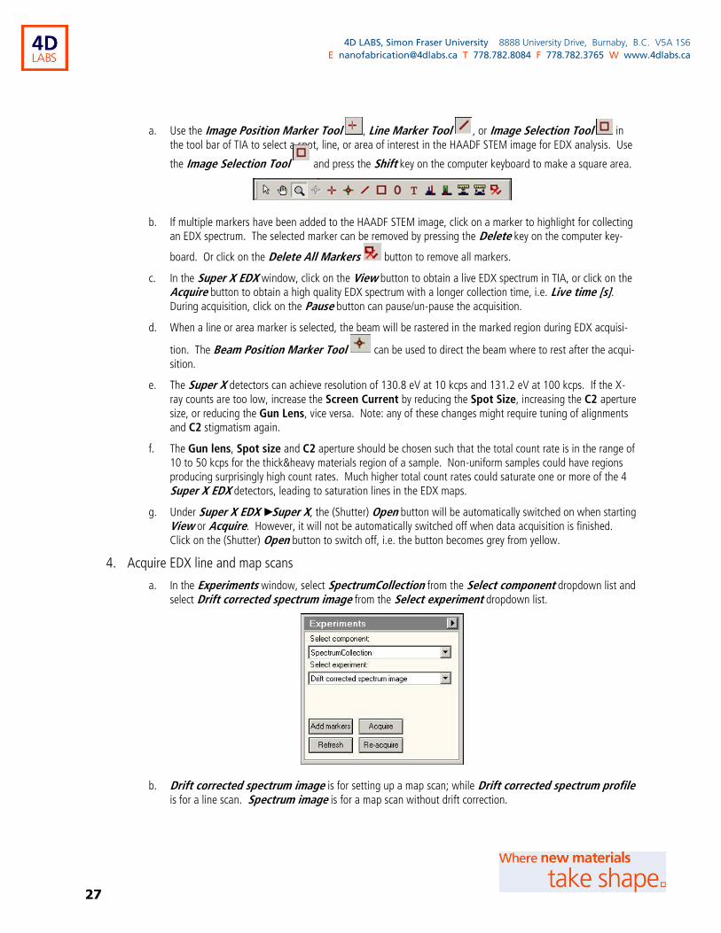
a. Use the Image Position Marker Tool , Line Marker Tool , or Image Selection Tool in the tool bar of TIA to select a spot, line, or area of interest in the HAADF STEM image for EDX analysis. Use
the Image Selection Tool and press the Shift key on the computer keyboard to make a square area.
b. If multiple markers have been added to the HAADF STEM image, click on a marker to highlight for collecting an EDX spectrum. The selected marker can be removed by pressing the Delete key on the computer key-
board. Or click on the Delete All Markers button to remove all markers.
c. In the Super X EDX window, click on the View button to obtain a live EDX spectrum in TIA, or click on the Acquire button to obtain a high quality EDX spectrum with a longer collection time, i.e. Live time [s]. During acquisition, click on the Pause button can pause/un-pause the acquisition.
d. When a line or area marker is selected, the beam will be rastered in the marked region during EDX acquisi-
tion. The Beam Position Marker Tool can be used to direct the beam where to rest after the acqui-sition.
e. The Super X detectors can achieve resolution of 130.8 eV at 10 kcps and 131.2 eV at 100 kcps. If the X-ray counts are too low, increase the Screen Current by reducing the Spot Size, increasing the C2 aperture size, or reducing the Gun Lens, vice versa. Note: any of these changes might require tuning of alignments and C2 stigmatism again.
f. The Gun lens, Spot size and C2 aperture should be chosen such that the total count rate is in the range of 10 to 50 kcps for the thick&heavy materials region of a sample. Non-uniform samples could have regions producing surprisingly high count rates. Much higher total count rates could saturate one or more of the 4 Super X EDX detectors, leading to saturation lines in the EDX maps.
g. Under Super X EDX ► Super X, the (Shutter) Open button will be automatically switched on when starting View or Acquire. However, it will not be automatically switched off when data acquisition is finished. Click on the (Shutter) Open button to switch off, i.e. the button becomes grey from yellow.
4. Acquire EDX line and map scans
a. In the Experiments window, select SpectrumCollection from the Select component dropdown list and select Drift corrected spectrum image from the Select experiment dropdown list.
b. Drift corrected spectrum image is for setting up a map scan; while Drift corrected spectrum profile is for a line scan. Spectrum image is for a map scan without drift correction.

28
4D LABS, Simon Fraser University 8888 University Drive, Burnaby, B.C. V5A 1S6
E [email protected] T 778.782.8084 F 778.782.3765 W www.4dlabs.ca
c. Click on the Add markers button in the Experiments window to add a spectrum position marker (orange rectangular open box) and a drift correction marker (yellow square open box) on the HAADF STEM image (in TIA). Click on either of the markers to highlight. Move the markers to desired locations of the HAADF STEM image or resize the markers.
d. In the Experiments ► Settings flap-out window, under Acquisition settings, set the desired image size/points (or profile size for a line scan) and the Dwell time (ms) (i.e. acquisition time per point).
e. Under Configuration settings, select Yes for Acquire EDX spectra and Acquire STEM image(s), and No for Acquire PEELS spectra, Acquire Ccd images, and Elemental processing. You can select Yes for Post Beam Blank to avoid burning of your sample after acquisition. However, remember to un-blank the beam before performing next acquisition, i.e. the Blank button in the STEM Imaging window appear-ing grey.

29
4D LABS, Simon Fraser University 8888 University Drive, Burnaby, B.C. V5A 1S6
E [email protected] T 778.782.8084 F 778.782.3765 W www.4dlabs.ca
f. Under Correction settings, set the Number of acquisitions in slice, i.e. the number of EDX acquisi-tions taken between checking the drift correction image. Choose smaller numbers for seriously drifting sam-ples.
g. (Optional) Click on the Refresh button in the Experiments window, a new HAADF STEM image will be collected and overwrite the previous HAADF STEM image for setting up. This is useful for making sure all markers are still in the desired locations.
h. Click on the Acquire button in the Experiments window to start EDX data collection. (Clicking on the Re-acquire button will start a new collection and overwrite the previous mapping results)
i. Once the acquisition is finished, the Super X dectetor shutters should be closed automatically. If not, click on the (Shutter) Open button under Super X EDX ► Super X to switch off, i.e. the button becomes grey from yellow.
5. If you are not collecting more EDX data, you may switch off the Super X detectors.
6. EDX data analysis with TIA
a. Select the Image Position Marker Tool and click onto the scanned line or image. Hold down the Alt key on the computer keyboard, click and drag the marker tool onto the spectrum (Note: the spectrum, not the graph!). Then you can drag the marker tool along the line or within the mapping image to view the spectrum at that point.
b. Click on the EDX Quant bar to display spectrum tools: Peak ID, Correct Background, Fit Peaks, Quan-tify ... Click on the Peak ID button to automatically identify elements in the highlighted spectrum. Or go
View > Periodic Table to open the periodic table. Manually add/remove an element by parking the curser over the element and pressing the Space key on the computer keyboard.
30
4D LABS, Simon Fraser University 8888 University Drive, Burnaby, B.C. V5A 1S6
E [email protected] T 778.782.8084 F 778.782.3765 W www.4dlabs.ca
c. Select the Energy Window Tool and draw a window to highlight a peak of interest. Click on the Unary Proc. Bar to display more tools and click on the Extract Map/Profile button to obtain a map/profile of the highlighted element.
d. Alternatively, click on the Generate Output button under the AutoMap bar to identify el-ements and generate maps automatically.
e. Save images in the shared folder (drive Z:, or my documents on ‘REM20646 (Rem20646)’) on the support computer. Go File>Save spectra in .emi format, or right click on the spectra and Export in other formats (.tiff, .bmp, etc.).
11. Acquiring EDX spectra and mapping with (Bruker) Esprit
1. Perform “Scanning TEM (STEM) alignment and HAADF STEM imaging”.
a. It is easier for some users to perform focus, stigmatism adjustments, and image optimization using the func-tions in the STEM Imaging windows and the live STEM images in TIA.
b. De-active the Search, Preview, Acquire, Focus, Scope, or Auto C/B buttons in the STEM Imaging windows before using the Esprit program. The Blank button can be still used for un-blanking/blanking the beam before/after an EDX acquisition.
c. (Expert user only) For optimum EDX performance, FEI suggested: smallest C1 aperture, 100 µm C2 aperture, Gun Lens 5, and Spot Size 3, giving a probe size of 1-2 nm.
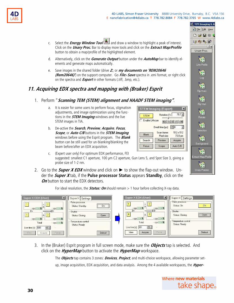
2. Go to the Super X EDX window and click on ► to show the flap-out window. Un-der the Super X tab, if the Pulse processor Status appears Standby, click on the On button to start the EDX detectors.
For ideal resolution, the Status: On should remain > 1 hour before collecting X-ray data.
3. In the (Bruker) Esprit program in full screen mode, make sure the Objects tap is selected. And click on the HyperMap button to activate the HyperMap workspace.
The Objects tap contains 3 zones: Devices, Project, and multi-choice workspace, allowing parameter set-
up, image acquisition, EDX acquisition, and data analysis. Among the 4 available workspaces, the Hyper-
31
4D LABS, Simon Fraser University 8888 University Drive, Burnaby, B.C. V5A 1S6
E [email protected] T 778.782.8084 F 778.782.3765 W www.4dlabs.ca
Map workspace allows EDX mapping with a full spectrum for each pixel and various routines for online or
post data processing. Users can still explore the Point, Line scan, and Mapping workspace for EDX data
collection on any point, line, and area of interest, with simplified functions.
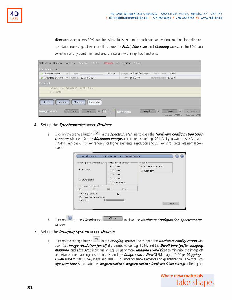
4. Set up the Spectrometer under Devices.
a. Click on the triangle button in the Spectrometer line to open the Hardware Configuration Spec-trometer window. Set the Maximum energy at a desired value, e.g. 20 keV if you want to see Mo Kα (17.441 keV) peak. 10 keV range is for higher elemental resolution and 20 keV is for better elemental cov-erage.
b. Click on or the Close button to close the Hardware Configuration Spectrometer window.
5. Set up the Imaging system under Devices.
a. Click on the triangle button in the Imaging system line to open the Hardware configuration win-dow. Set Image resolution [pixel] at a desired value, e.g. 1024. Set the Dwell time [µs] for Imaging, Mapping, and Line scan individually, e.g. 20 µs or more Imaging Dwell time to minimize the image off-set between the mapping area of interest and the Image scan > New STEM image; 10-50 µs Mapping Dwell time for fast survey maps and 1000 µs or more for trace elements and quantification. The total Im-age scan time is calculated by Image resolution X Image resolution X Dwell time X Line average, offering an

32
4D LABS, Simon Fraser University 8888 University Drive, Burnaby, B.C. V5A 1S6
E [email protected] T 778.782.8084 F 778.782.3765 W www.4dlabs.ca
estimated running time. Clicking on the Drift correction button will open the Image drift correction window. Users can vary the Correction interval and Dwell time for correction image.
b. Click on to close the Image drift correction window. Click on or the Close button
to close the Hardware Configuration window.
6. Save the measurement parameters.
Click on the triangle button to the right of Devices, to Save your measurement setup under Measure
method, so that you can Load the same measurement setup next time.
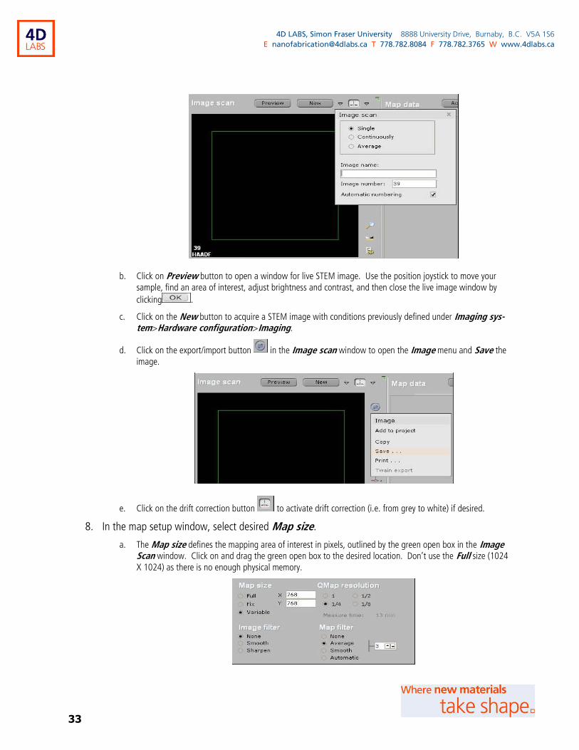
7. In the Image scan window, collect a main STEM image for setting up the mapping area of inter-est.
a. Click on the triangle button to the right of the New button, to open the Image scan setup window. This window allows users to set up scan mode for the main STEM image and to label the image with an Im-age name and (optional) an Image number (the name and number will be burnt on the image).
33
4D LABS, Simon Fraser University 8888 University Drive, Burnaby, B.C. V5A 1S6
E [email protected] T 778.782.8084 F 778.782.3765 W www.4dlabs.ca
b. Click on Preview button to open a window for live STEM image. Use the position joystick to move your sample, find an area of interest, adjust brightness and contrast, and then close the live image window by
clicking .
c. Click on the New button to acquire a STEM image with conditions previously defined under Imaging sys-tem>Hardware configuration>Imaging.
d. Click on the export/import button in the Image scan window to open the Image menu and Save the image.
e. Click on the drift correction button to activate drift correction (i.e. from grey to white) if desired.
8. In the map setup window, select desired Map size.
a. The Map size defines the mapping area of interest in pixels, outlined by the green open box in the Image Scan window. Click on and drag the green open box to the desired location. Don’t use the Full size (1024 X 1024) as there is no enough physical memory.
34
4D LABS, Simon Fraser University 8888 University Drive, Burnaby, B.C. V5A 1S6
E [email protected] T 778.782.8084 F 778.782.3765 W www.4dlabs.ca
b. The Image filter allows users to digitally alter appearance of the image collected during mapping.
c. The QMap resolution allows users to convert up to 8 pixels of spectrum data to 1 pixel in the final EDX maps during quantified mapping, in order to shorten the Measure time (i.e. data collection plus pro-cessing). However, in the HyperMap workspace, quantified mapping can be performed after data collec-tion and therefore in such a case the actual data processing time is much shorter than the displayed Meas-ure time.
d. The Map filter allows users to digitally alter appearance of the quantified elemental maps.
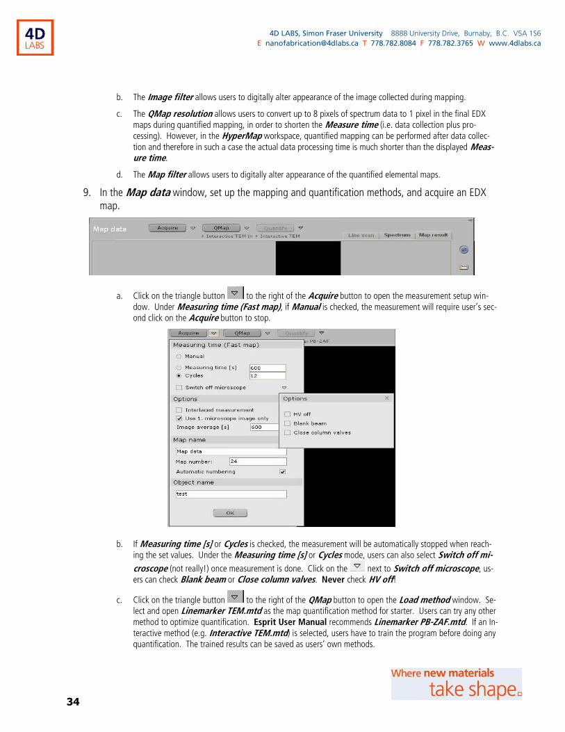
9. In the Map data window, set up the mapping and quantification methods, and acquire an EDX map.
a. Click on the triangle button to the right of the Acquire button to open the measurement setup win-dow. Under Measuring time (Fast map), if Manual is checked, the measurement will require user’s sec-ond click on the Acquire button to stop.
b. If Measuring time [s] or Cycles is checked, the measurement will be automatically stopped when reach-ing the set values. Under the Measuring time [s] or Cycles mode, users can also select Switch off mi-
croscope (not really!) once measurement is done. Click on the next to Switch off microscope, us-ers can check Blank beam or Close column valves. Never check HV off!
c. Click on the triangle button to the right of the QMap button to open the Load method window. Se-lect and open Linemarker TEM.mtd as the map quantification method for starter. Users can try any other method to optimize quantification. Esprit User Manual recommends Linemarker PB-ZAF.mtd. If an In-teractive method (e.g. Interactive TEM.mtd) is selected, users have to train the program before doing any quantification. The trained results can be saved as users’ own methods.

35
4D LABS, Simon Fraser University 8888 University Drive, Burnaby, B.C. V5A 1S6
E [email protected] T 778.782.8084 F 778.782.3765 W www.4dlabs.ca
d. Click on the triangle button to the right of the Quantify button to open the Load method window. Select and open Linemarker TEM.mtd as the quantification method for starter.
e. Click on the loaded method under either the QMap or Quantify button , e.g. ►Interactive TEM. An Editor for Evaluation Methods will pop up. Users can create their own methods by modifying the loaded method.
f. Click on the Acquire button to start EDX mapping. Click again the Acquire button will become a Stop
button , and the mapping will stop after finishing the current frame. Click on the Stop but-ton again to stop the mapping immediately.
g. Click on the sleeping bed button to select main elements to monitor from the pop-up Table of ele-ments. To keep high acquisition speed, select 2 to 3 elements only. Click on the Auto ▼ button under the Table of elements to set/eliminate forbidden elements (the elements that should not appear in the user’s sample).
10. In the Element images window, click on the check box below each image to overlay/no-overlay the image in the Map data window. Click on the color button to choose your favourite color for an image.

36
4D LABS, Simon Fraser University 8888 University Drive, Burnaby, B.C. V5A 1S6
E [email protected] T 778.782.8084 F 778.782.3765 W www.4dlabs.ca
11. Once the acquisition is done. Click on the export/import button in the Map result tab of the Map data window to Save the acquisition result under Database.
12. If you are not collecting more EDX data, you may switch off the Super X de-tectors.
13. EDX data analysis with (Bruker) Esprit.
a. To investigate an area of interest in the resultant map, first left-click on the
pipette button to activate the selection tool. Right-click on the pi-
pette button to show the dropdown list of various markers. Select
and place a marker (e.g. point-marker ) on the map. Click on the Spectrum tab of the Map data window to show the EDX spectrum of
the point of interest. Click on the sleeping bed button to select or auto-indentify main elements. Click on the Quantify button of the Map data window to obtain elemental composition (displayed at the bottom of the Map data window under Mass-% (Norm.)).
b. If the line-marker is selected, user can obtain line profile anywhere in the map.
c. Click on the QMap button to quantify element maps, i.e. concentration maps.
d. Element maps can be Saved under Map data to image files, e.g. .bmp format.
e. Various data and processing results can also be Added to project and save all together as one Project package.
37
4D LABS, Simon Fraser University 8888 University Drive, Burnaby, B.C. V5A 1S6
E [email protected] T 778.782.8084 F 778.782.3765 W www.4dlabs.ca
12. Acquiring EELS spectra under TEM mode in DigitalMicrograph (DM)
1. Optimize the beam under TEM mode by performing “Preparation for imaging” and “TEM alignment”.
a. Choose Gun Lens 6 and Spot Size 3.
b. Set the magnification to the SA xxxx range.
2. Find an open/empty area in the sample that is larger than the GIF aperture, and align the beam with the GIF entrance aperture.
a. Click on the GIF Detector Area button ( the one on the right here) to show the GIF aperture marker in the Flucam Viewer.
b. If the open/empty area is smaller than the GIF entrance aperture, increase magnification may help.
c. Use the beam trackball to align the beam center with the GIF entrance aperture.
d. Turn the Intensity knob clockwise to expand the beam in order to have an Exposure time between 5 and 20 s.
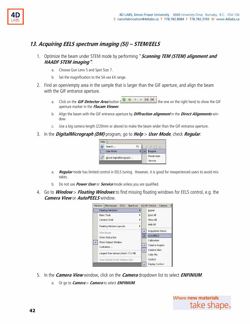
3. In the DigitalMicrograph (DM) program, go to Help > User Mode, check Regular.
a. Regular mode has limited control in EELS tuning. However, it is good for inexperienced users to avoid mis-takes.
b. Do not use Power User or Service mode unless you are qualified.
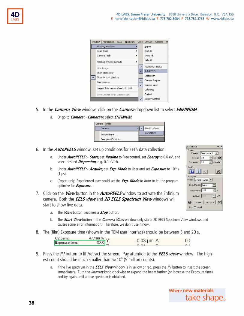
4. Go to Window > Floating Windows to find missing floating windows for EELS control, e.g. the Camera View or AutoPEELS window.
38
4D LABS, Simon Fraser University 8888 University Drive, Burnaby, B.C. V5A 1S6
E [email protected] T 778.782.8084 F 778.782.3765 W www.4dlabs.ca
5. In the Camera View window, click on the Camera dropdown list to select ENFINIUM.
a. Or go to Camera > Camera to select ENFINIUM.
6. In the AutoPEELS window, set up conditions for EELS data collection.
a. Under AutoPEELS > State, set Regime to Free control, set Energy to 0.0 eV, and select desired Dispersion, e.g. 0.1 eV/ch.
b. Under AutoPEELS > Acquire, set Exp. Mode to User and set Exposure to 10-6 s (1 µs).
c. (Expert only) Experienced user could set the Exp. Mode to Auto to let the program optimize for Exposure.
7. Click on the View button in the AutoPEELS window to activate the Enfinium camera. Both the EELS view and 2D EELS Spectrum View windows will start to show live data.
a. The View button becomes a Stop button.
b. The Start View button in the Camera View window only starts 2D EELS Spectrum View windows and causes some error information. Therefore, we don’t use it now.
8. The (film) Exposure time (shown in the TEM user interface) should be between 5 and 20 s.
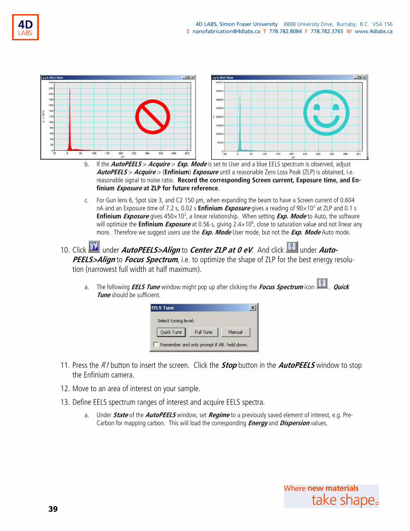
9. Press the R1 button to lift/retract the screen. Pay attention to the EELS view window. The high-est count should be much smaller than 5×10⁶ (5 million counts).
a. If the live spectrum in the EELS View window is in yellow or red, press the R1 button to insert the screen immediately. Turn the Intensity knob clockwise to expand the beam further (or increase the Exposure time) and try again until a blue spectrum is obtained.
39
4D LABS, Simon Fraser University 8888 University Drive, Burnaby, B.C. V5A 1S6
E [email protected] T 778.782.8084 F 778.782.3765 W www.4dlabs.ca
b. If the AutoPEELS > Acquire > Exp. Mode is set to User and a blue EELS spectrum is observed, adjust AutoPEELS > Acquire > (Enfinium) Exposure until a reasonable Zero Loss Peak (ZLP) is obtained, i.e. reasonable signal to noise ratio. Record the corresponding Screen current, Exposure time, and En-finium Exposure at ZLP for future reference.
c. For Gun lens 6, Spot size 3, and C2 150 µm, when expanding the beam to have a Screen current of 0.604 nA and an Exposure time of 7.2 s, 0.02 s Enfinium Exposure gives a reading of 90×103 at ZLP and 0.1 s Enfinium Exposure gives 450×103, a linear relationship. When setting Exp. Mode to Auto, the software will optimize the Enfinium Exposure at 0.56 s, giving 2.4×10⁶, close to saturation value and not linear any more. Therefore we suggest users use the Exp. Mode User mode, but not the Exp. Mode Auto mode.
10. Click under AutoPEELS>Align to Center ZLP at 0 eV. And click under Auto-PEELS>Align to Focus Spectrum, i.e. to optimize the shape of ZLP for the best energy resolu-tion (narrowest full width at half maximum).
a. The following EELS Tune window might pop up after clicking the Focus Spectrum icon . Quick Tune should be sufficient.
11. Press the R1 button to insert the screen. Click the Stop button in the AutoPEELS window to stop the Enfinium camera.
12. Move to an area of interest on your sample.
13. Define EELS spectrum ranges of interest and acquire EELS spectra.
a. Under State of the AutoPEELS window, set Regime to a previously saved element of interest, e.g. Pre-Carbon for mapping carbon. This will load the corresponding Energy and Dispersion values.
☺
40
4D LABS, Simon Fraser University 8888 University Drive, Burnaby, B.C. V5A 1S6
E [email protected] T 778.782.8084 F 778.782.3765 W www.4dlabs.ca
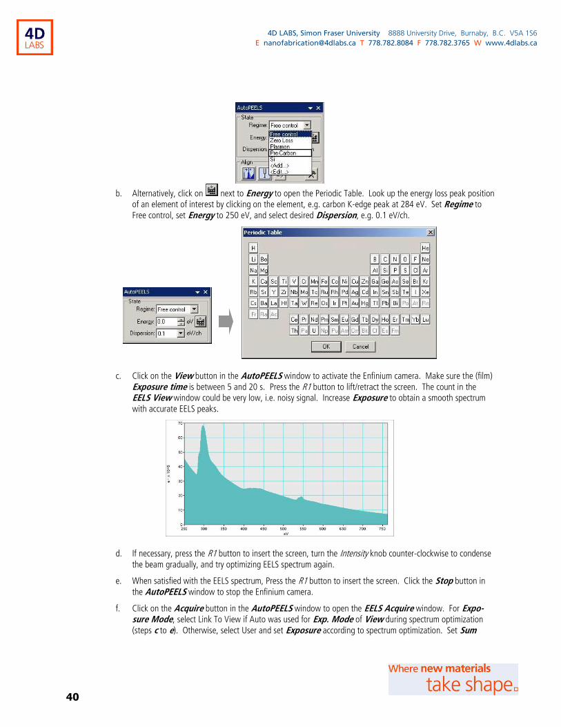
b. Alternatively, click on next to Energy to open the Periodic Table. Look up the energy loss peak position of an element of interest by clicking on the element, e.g. carbon K-edge peak at 284 eV. Set Regime to Free control, set Energy to 250 eV, and select desired Dispersion, e.g. 0.1 eV/ch.
c. Click on the View button in the AutoPEELS window to activate the Enfinium camera. Make sure the (film) Exposure time is between 5 and 20 s. Press the R1 button to lift/retract the screen. The count in the EELS View window could be very low, i.e. noisy signal. Increase Exposure to obtain a smooth spectrum with accurate EELS peaks.
d. If necessary, press the R1 button to insert the screen, turn the Intensity knob counter-clockwise to condense the beam gradually, and try optimizing EELS spectrum again.
e. When satisfied with the EELS spectrum, Press the R1 button to insert the screen. Click the Stop button in the AutoPEELS window to stop the Enfinium camera.
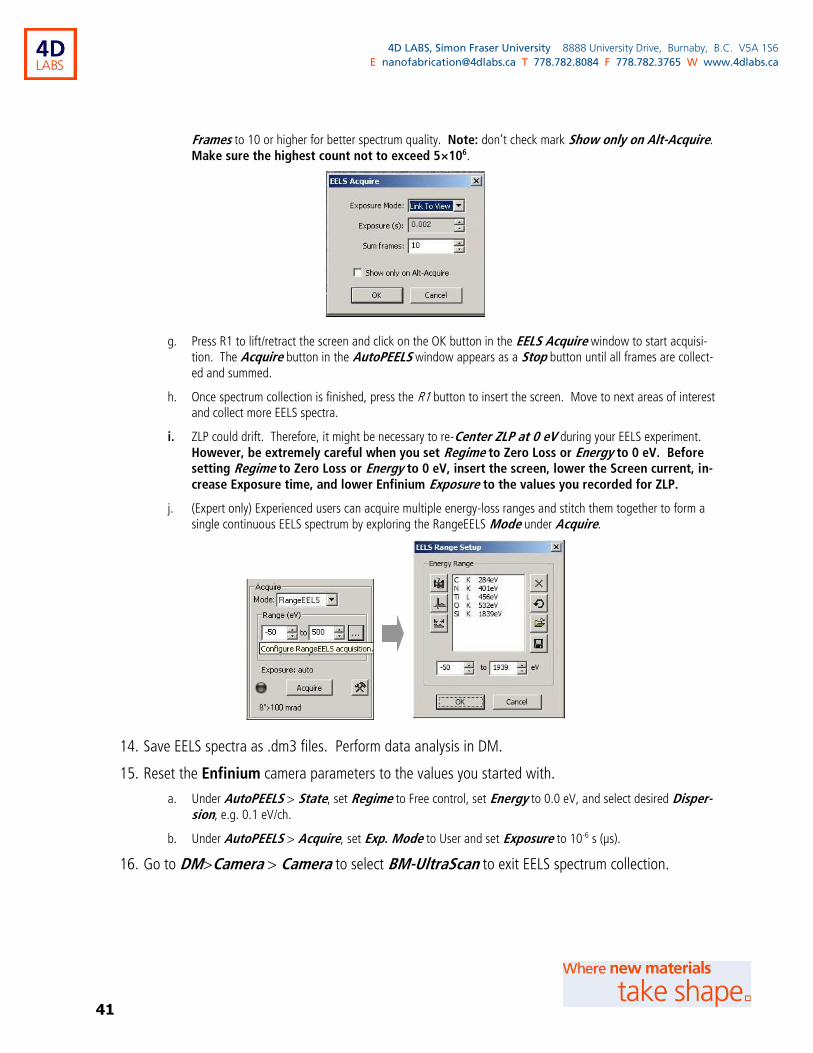
f. Click on the Acquire button in the AutoPEELS window to open the EELS Acquire window. For Expo-sure Mode, select Link To View if Auto was used for Exp. Mode of View during spectrum optimization (steps c to e). Otherwise, select User and set Exposure according to spectrum optimization. Set Sum
41
4D LABS, Simon Fraser University 8888 University Drive, Burnaby, B.C. V5A 1S6
E [email protected] T 778.782.8084 F 778.782.3765 W www.4dlabs.ca
Frames to 10 or higher for better spectrum quality. Note: don’t check mark Show only on Alt-Acquire. Make sure the highest count not to exceed 5×10⁶.
g. Press R1 to lift/retract the screen and click on the OK button in the EELS Acquire window to start acquisi-tion. The Acquire button in the AutoPEELS window appears as a Stop button until all frames are collect-ed and summed.
h. Once spectrum collection is finished, press the R1 button to insert the screen. Move to next areas of interest and collect more EELS spectra.
i. ZLP could drift. Therefore, it might be necessary to re-Center ZLP at 0 eV during your EELS experiment. However, be extremely careful when you set Regime to Zero Loss or Energy to 0 eV. Before setting Regime to Zero Loss or Energy to 0 eV, insert the screen, lower the Screen current, in-crease Exposure time, and lower Enfinium Exposure to the values you recorded for ZLP.
j. (Expert only) Experienced users can acquire multiple energy-loss ranges and stitch them together to form a single continuous EELS spectrum by exploring the RangeEELS Mode under Acquire.
14. Save EELS spectra as .dm3 files. Perform data analysis in DM.
15. Reset the Enfinium camera parameters to the values you started with.
a. Under AutoPEELS > State, set Regime to Free control, set Energy to 0.0 eV, and select desired Disper-sion, e.g. 0.1 eV/ch.
b. Under AutoPEELS > Acquire, set Exp. Mode to User and set Exposure to 10-6 s (µs).
16. Go to DM>Camera > Camera to select BM-UltraScan to exit EELS spectrum collection.
42
4D LABS, Simon Fraser University 8888 University Drive, Burnaby, B.C. V5A 1S6
E [email protected] T 778.782.8084 F 778.782.3765 W www.4dlabs.ca
13. Acquiring EELS spectrum imaging (SI) – STEM/EELS
1. Optimize the beam under STEM mode by performing “Scanning TEM (STEM) alignment and HAADF STEM imaging”.
a. Choose Gun Lens 5 and Spot Size 7.
b. Set the magnification to the SA xxx kX range.
2. Find an open/empty area in the sample that is larger than the GIF aperture, and align the beam with the GIF entrance aperture.
a. Click on the GIF Detector Area button ( the one on the right here) to show the GIF aperture marker in the Flucam Viewer.
b. Align the beam with the GIF entrance aperture by Diffraction alignment in the Direct Alignments win-dow.
c. Use a big camera length (220mm or above) to make the beam wider than the GIF entrance aperture.
3. In the DigitalMicrograph (DM) program, go to Help > User Mode, check Regular.
a. Regular mode has limited control in EELS tuning. However, it is good for inexperienced users to avoid mis-takes.
b. Do not use Power User or Service mode unless you are qualified.
4. Go to Window > Floating Windows to find missing floating windows for EELS control, e.g. the Camera View or AutoPEELS window.
5. In the Camera View window, click on the Camera dropdown list to select ENFINIUM.
a. Or go to Camera > Camera to select ENFINIUM.
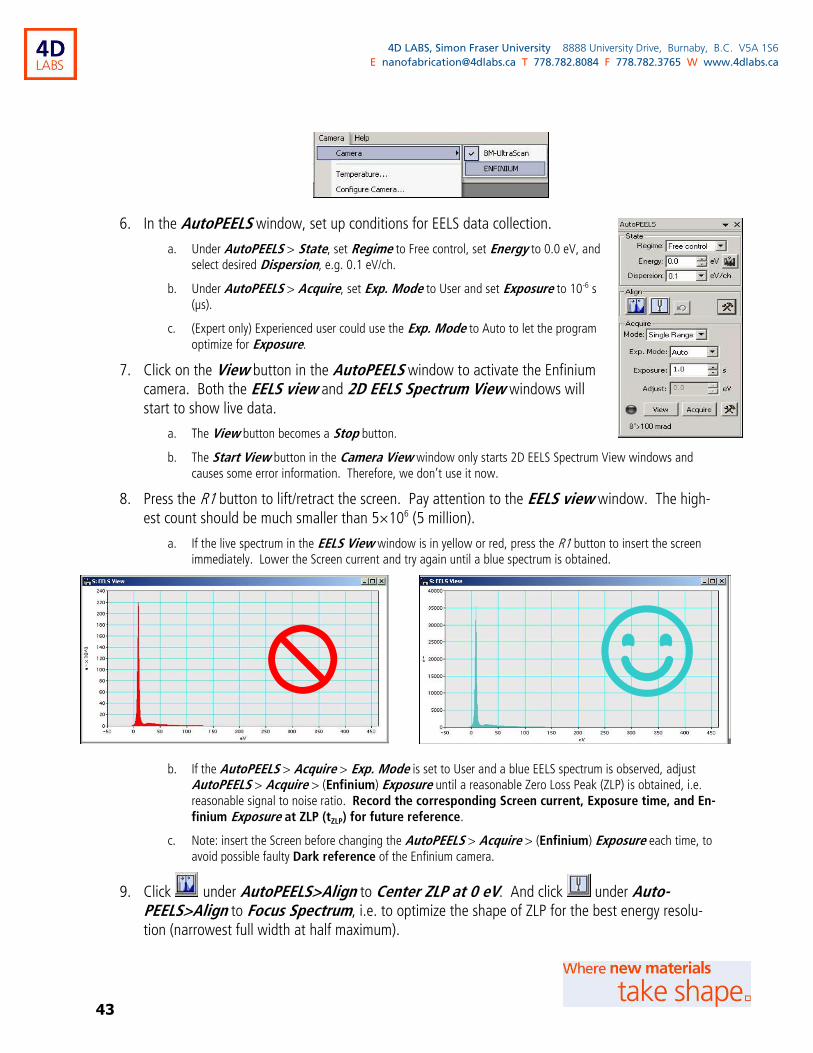
43
4D LABS, Simon Fraser University 8888 University Drive, Burnaby, B.C. V5A 1S6
E [email protected] T 778.782.8084 F 778.782.3765 W www.4dlabs.ca
6. In the AutoPEELS window, set up conditions for EELS data collection.
a. Under AutoPEELS > State, set Regime to Free control, set Energy to 0.0 eV, and select desired Dispersion, e.g. 0.1 eV/ch.
b. Under AutoPEELS > Acquire, set Exp. Mode to User and set Exposure to 10-6 s (µs).
c. (Expert only) Experienced user could use the Exp. Mode to Auto to let the program
optimize for Exposure.
7. Click on the View button in the AutoPEELS window to activate the Enfinium camera. Both the EELS view and 2D EELS Spectrum View windows will start to show live data.
a. The View button becomes a Stop button.
b. The Start View button in the Camera View window only starts 2D EELS Spectrum View windows and causes some error information. Therefore, we don’t use it now.
8. Press the R1 button to lift/retract the screen. Pay attention to the EELS view window. The high-est count should be much smaller than 5×10⁶ (5 million).
a. If the live spectrum in the EELS View window is in yellow or red, press the R1 button to insert the screen immediately. Lower the Screen current and try again until a blue spectrum is obtained.
b. If the AutoPEELS > Acquire > Exp. Mode is set to User and a blue EELS spectrum is observed, adjust AutoPEELS > Acquire > (Enfinium) Exposure until a reasonable Zero Loss Peak (ZLP) is obtained, i.e. reasonable signal to noise ratio. Record the corresponding Screen current, Exposure time, and En-
finium Exposure at ZLP (tZLP) for future reference.
c. Note: insert the Screen before changing the AutoPEELS > Acquire > (Enfinium) Exposure each time, to avoid possible faulty Dark reference of the Enfinium camera.
9. Click under AutoPEELS>Align to Center ZLP at 0 eV. And click under Auto-PEELS>Align to Focus Spectrum, i.e. to optimize the shape of ZLP for the best energy resolu-tion (narrowest full width at half maximum).
☺
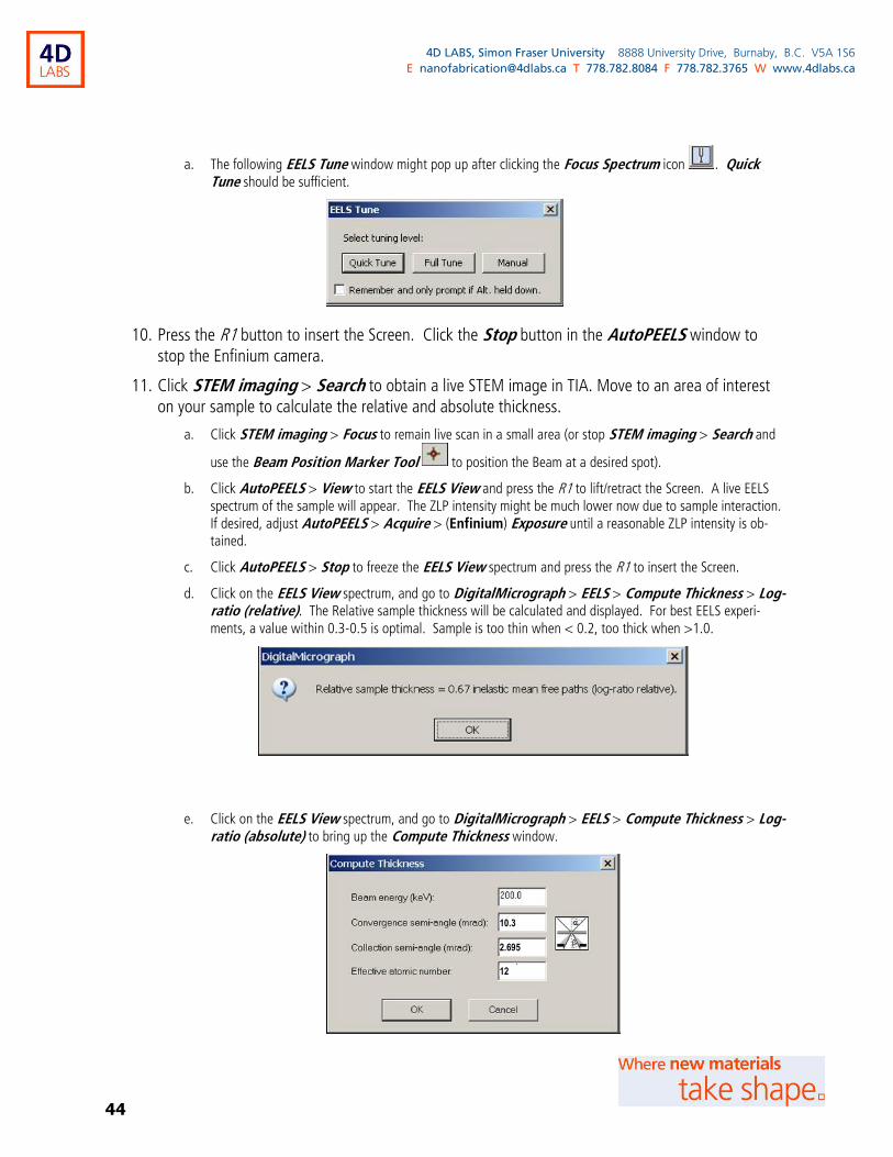
44
4D LABS, Simon Fraser University 8888 University Drive, Burnaby, B.C. V5A 1S6
E [email protected] T 778.782.8084 F 778.782.3765 W www.4dlabs.ca
a. The following EELS Tune window might pop up after clicking the Focus Spectrum icon . Quick Tune should be sufficient.
10. Press the R1 button to insert the Screen. Click the Stop button in the AutoPEELS window to stop the Enfinium camera.
11. Click STEM imaging > Search to obtain a live STEM image in TIA. Move to an area of interest on your sample to calculate the relative and absolute thickness.
a. Click STEM imaging > Focus to remain live scan in a small area (or stop STEM imaging > Search and
use the Beam Position Marker Tool to position the Beam at a desired spot).
b. Click AutoPEELS > View to start the EELS View and press the R1 to lift/retract the Screen. A live EELS spectrum of the sample will appear. The ZLP intensity might be much lower now due to sample interaction. If desired, adjust AutoPEELS > Acquire > (Enfinium) Exposure until a reasonable ZLP intensity is ob-tained.
c. Click AutoPEELS > Stop to freeze the EELS View spectrum and press the R1 to insert the Screen.
d. Click on the EELS View spectrum, and go to DigitalMicrograph > EELS > Compute Thickness > Log-ratio (relative). The Relative sample thickness will be calculated and displayed. For best EELS experi-ments, a value within 0.3-0.5 is optimal. Sample is too thin when < 0.2, too thick when >1.0.
e. Click on the EELS View spectrum, and go to DigitalMicrograph > EELS > Compute Thickness > Log-ratio (absolute) to bring up the Compute Thickness window.
10.3
2.695
12
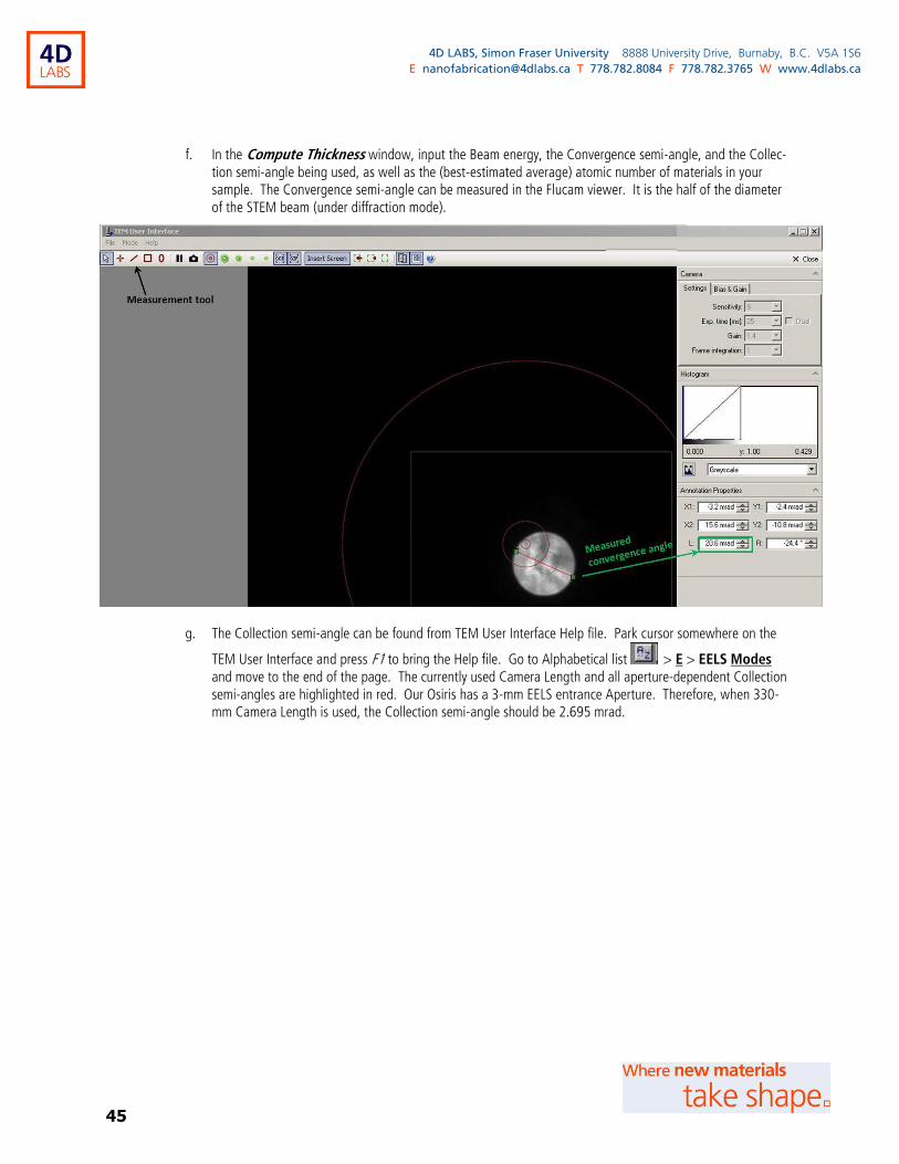
45
4D LABS, Simon Fraser University 8888 University Drive, Burnaby, B.C. V5A 1S6
E [email protected] T 778.782.8084 F 778.782.3765 W www.4dlabs.ca
f. In the Compute Thickness window, input the Beam energy, the Convergence semi-angle, and the Collec-tion semi-angle being used, as well as the (best-estimated average) atomic number of materials in your sample. The Convergence semi-angle can be measured in the Flucam viewer. It is the half of the diameter of the STEM beam (under diffraction mode).
g. The Collection semi-angle can be found from TEM User Interface Help file. Park cursor somewhere on the
TEM User Interface and press F1 to bring the Help file. Go to Alphabetical list > E > EELS Modes and move to the end of the page. The currently used Camera Length and all aperture-dependent Collection semi-angles are highlighted in red. Our Osiris has a 3-mm EELS entrance Aperture. Therefore, when 330-mm Camera Length is used, the Collection semi-angle should be 2.695 mrad.
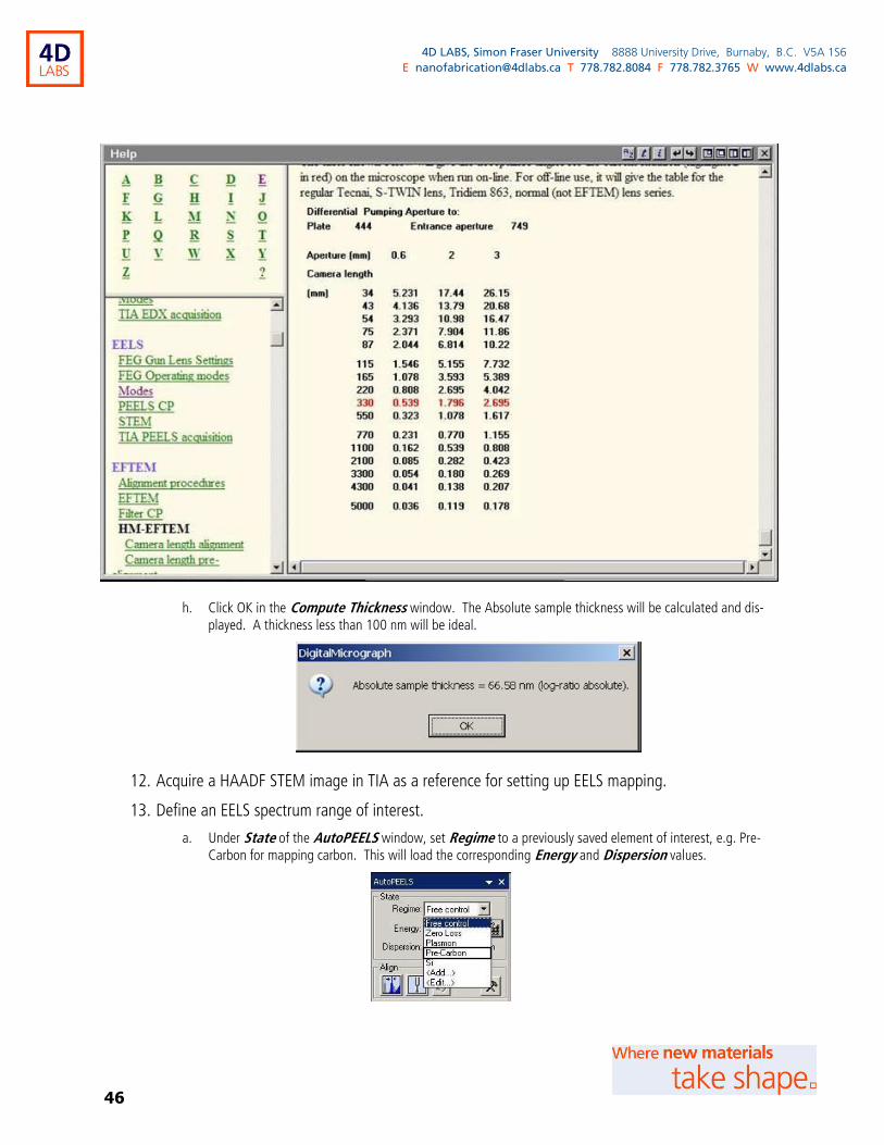
46
4D LABS, Simon Fraser University 8888 University Drive, Burnaby, B.C. V5A 1S6
E [email protected] T 778.782.8084 F 778.782.3765 W www.4dlabs.ca
h. Click OK in the Compute Thickness window. The Absolute sample thickness will be calculated and dis-played. A thickness less than 100 nm will be ideal.
12. Acquire a HAADF STEM image in TIA as a reference for setting up EELS mapping.
13. Define an EELS spectrum range of interest.
a. Under State of the AutoPEELS window, set Regime to a previously saved element of interest, e.g. Pre-Carbon for mapping carbon. This will load the corresponding Energy and Dispersion values.

47
4D LABS, Simon Fraser University 8888 University Drive, Burnaby, B.C. V5A 1S6
E [email protected] T 778.782.8084 F 778.782.3765 W www.4dlabs.ca
b. Alternatively, click on next to Energy to open the Periodic Table. Look up the energy loss peak position of an element of interest by clicking on the element, e.g. carbon K-edge peak at 284 eV. Set Regime to Free control, set Energy to 250 eV, and select desired Dispersion, e.g. 0.1 eV/ch.
c. Click on the View button in the AutoPEELS window to activate the Enfinium camera. Press the R1 button to lift/retract the screen. The count in the EELS View window could be very low, i.e. noisy signal. Increase Exposure to obtain a smooth spectrum with accurate EELS peaks.
d. If necessary, press the R1 button to insert the screen, gradually increase Screen current by decreasing the Camera Length, and then try optimizing EELS spectrum again.
e. When satisfied with the EELS spectrum, Press the R1 button to insert the screen. Click the Stop button in the AutoPEELS window to stop the Enfinium camera. Record the Enfinium Exposure for the spectrum range of interest (tSRI).
f. From now on to the end of your EELS experiment, be extremely careful when you set Regime to Zero Loss or Energy to 0 eV. Before setting Regime to Zero Loss or Energy to 0 eV, insert the screen, lower the Screen current, increase Exposure time, and lower Enfinium Exposure to the values you recorded for ZLP.
g. ZLP could drift. Therefore, it might be necessary to re-Center ZLP at 0 eV during your EELS experiment.
14. Acquire EELS mapping.
a. In the Experiments window, select SpectrumCollection from the Select component dropdown list and select Drift corrected spectrum image from the Select experiment dropdown list.

48
4D LABS, Simon Fraser University 8888 University Drive, Burnaby, B.C. V5A 1S6
E [email protected] T 778.782.8084 F 778.782.3765 W www.4dlabs.ca
b. Drift corrected spectrum image is for setting up a map scan; while Drift corrected spectrum profile
is for a line scan. Spectrum image is for a map scan without drift correction.
c. Click on the Add markers button in the Experiments window to add a spectrum position marker (orange rectangular open box) and a drift correction marker (yellow square open box) on the HAADF STEM image (in TIA). Click on either of the markers to highlight. Move the markers to desired locations of the HAADF STEM image or resize the markers.
d. In the Experiments ► Settings flap-out window, under Acquisition settings, set the desired image size/points (or profile size for a line scan) and the Dwell time (ms) (i.e. acquisition time per point. This should be tSRI). Set Number PEELS spectra to 1 or more (the number of EELS spectra to be collected with-in the set Dwell time and added together for the investigated point).
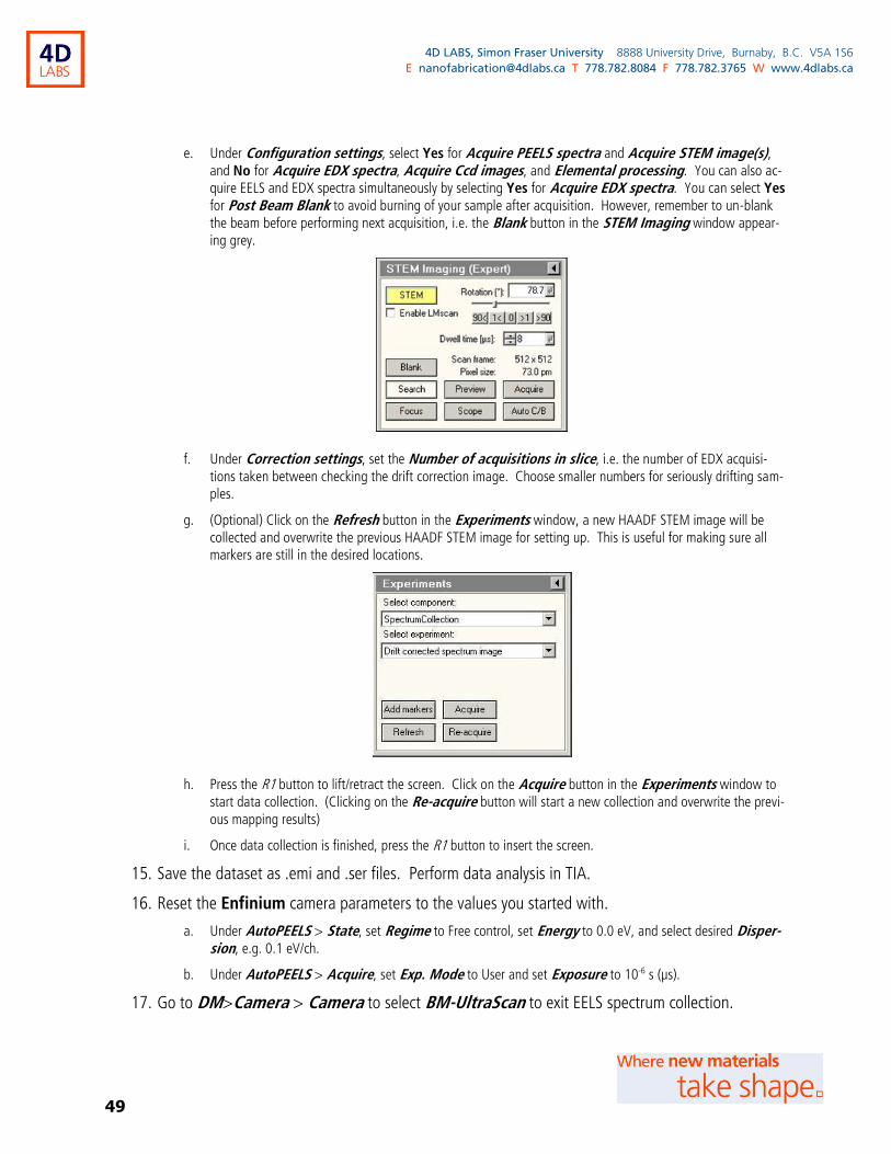
49
4D LABS, Simon Fraser University 8888 University Drive, Burnaby, B.C. V5A 1S6
E [email protected] T 778.782.8084 F 778.782.3765 W www.4dlabs.ca
e. Under Configuration settings, select Yes for Acquire PEELS spectra and Acquire STEM image(s), and No for Acquire EDX spectra, Acquire Ccd images, and Elemental processing. You can also ac-quire EELS and EDX spectra simultaneously by selecting Yes for Acquire EDX spectra. You can select Yes for Post Beam Blank to avoid burning of your sample after acquisition. However, remember to un-blank the beam before performing next acquisition, i.e. the Blank button in the STEM Imaging window appear-ing grey.
f. Under Correction settings, set the Number of acquisitions in slice, i.e. the number of EDX acquisi-tions taken between checking the drift correction image. Choose smaller numbers for seriously drifting sam-ples.
g. (Optional) Click on the Refresh button in the Experiments window, a new HAADF STEM image will be collected and overwrite the previous HAADF STEM image for setting up. This is useful for making sure all markers are still in the desired locations.
h. Press the R1 button to lift/retract the screen. Click on the Acquire button in the Experiments window to start data collection. (Clicking on the Re-acquire button will start a new collection and overwrite the previ-ous mapping results)
i. Once data collection is finished, press the R1 button to insert the screen.
15. Save the dataset as .emi and .ser files. Perform data analysis in TIA.
16. Reset the Enfinium camera parameters to the values you started with.
a. Under AutoPEELS > State, set Regime to Free control, set Energy to 0.0 eV, and select desired Disper-sion, e.g. 0.1 eV/ch.
b. Under AutoPEELS > Acquire, set Exp. Mode to User and set Exposure to 10-6 s (µs).
17. Go to DM>Camera > Camera to select BM-UltraScan to exit EELS spectrum collection.
50
4D LABS, Simon Fraser University 8888 University Drive, Burnaby, B.C. V5A 1S6
E [email protected] T 778.782.8084 F 778.782.3765 W www.4dlabs.ca
14. Completing work
1. Make sure the Objective and Selected Area apertures are out.
Condenser 1 aperture should always be at 2000 µm.
Condenser 2 aperture is typically at 150 µm for TEM imaging. However, it
could be left at 100, 70, or 50 µm.
2. Make sure the cameras/detectors are out and the screen
is inserted.
The Insert Screen button appears blue and the Screen Inserted status should appear in the Flucam
Viewer.
3. Make sure the system is under the TEM mode and a low SA xxxx X magnification.
This magnification is essential to maintain stable Objective lens current and prevent thermal drift for the next us-
er.
4. Close the Column valves.
5. Make sure the Col. Valves Closed button appears yellow!!!
The Column Valves Closed status should also appear in the Flucam Viewer.
6. Reset the specimen holder.
Under Stage2 → ► flap-out → Control, click on the Holder button under Reset.
51
4D LABS, Simon Fraser University 8888 University Drive, Burnaby, B.C. V5A 1S6
E [email protected] T 778.782.8084 F 778.782.3765 W www.4dlabs.ca
7. Make sure the Stage coordinates and tilts are at zero.
8. Unload the specimen holder (See “Unloading a TEM specimen holder” for details).
9. Remove your sample from the specimen holder, and keep the specimen holder in a holder station chamber with its cap on.
10. If you were working under your own account, log out first and then log in as general_user.
a. Close the software in the following order:
TEM Imaging & Analysis (TIA)
Esprit
Gatan Digital Micrograph (Click on the Exit without saving button when asking to Save GIF Settings)
Flucam Viewer
TEM User Interface
b. Log off the Windows and then log in the Windows as general_user/osiris.
c. Start the software in the following order (Allow some waiting time between loading programs to avoid con-
fusing the communication.):
TEM User Interface
Flucam Viewer
Gatan Digital Micrograph
Esprit (edx/***, click on the login button)
52
4D LABS, Simon Fraser University 8888 University Drive, Burnaby, B.C. V5A 1S6
E [email protected] T 778.782.8084 F 778.782.3765 W www.4dlabs.ca
TEM Imaging & Analysis (TIA)
11. If the Cold trap LN2 (liquid nitrogen) is lower 10%, ask Xin Zhang if the liquid nitrogen dewar needs to be filled up, or a Cryo Cycle is planned for the day.
12. Copy your data to your USB memory and remove your data from the support computer.
Perform a virus scan on your storage devices using OfficeScan before copying data.
NEVER insert a flash drive into the Control PC.
13. Log out your session on the logbook and make an online ticket for your session.
14. If the machine becomes unusable during your run, please let the tool managers know the situation immediately and leave a warning note for incoming users.
15. Turn off the TEM room lights and leave.
15. Unloading a TEM specimen holder
1. Reset the specimen holder.
Under Stage2 → ► flap-out → Control, click on the Holder button under Reset.
2. Keep the room door open when unloading a TEM specimen holder.
Make sure the room door is securely locked at the open position so that it won’t surprisingly bump into you as
you are unloading the TEM holder.
3. Open the microscope front door and take the bowl cover off the CompuStage.
4. Disconnect the holder cable if the holder is not a sin-gle-tilt one.
5. Push the blue airlock panel with one hand, when firmly grabbing the specimen holder handle to pull with the other hand.
Press
fingers
here
Trigger to
airlock
pump down

53
4D LABS, Simon Fraser University 8888 University Drive, Burnaby, B.C. V5A 1S6
E [email protected] T 778.782.8084 F 778.782.3765 W www.4dlabs.ca
a. When you pulling the specimen holder out, the vacuum pulls the holder against you. Therefore, to avoid po-tential vacuum leak, you want to press you fingers against the blue airlock panel to minimize its movement with the holder.
b. Pull the specimen holder straight out about 3 inch-es, until it stops.
c. Then gently turn it clockwise until it stops. No pull-ing during turning!!! You can switch hands if needed as your other hand is free now. However, don’t let it turn back.
d. Now you can gently pull the holder out a little more, until it pops loose from vacuum. You still need to push the blue airlock panel a little bit.
Don’t turn the holder when pulling it.
e. Pull the holder out the rest of the way. Try to avoid hitting anything on the way out.
f. Hitting the copper trigger (on the left side in the hole) might initiate the airlock pump down.
6. Seat the specimen holder on a holder station to remove/exchange your sample.
7. Put the bowl cover back on the CompuStage. Close the microscope front door.
8. Close the room door.
References and Files
FEI Tecnai Osiris S/TEM manual and training notes.
Contact Information
Questions or comments in regard to this document or the Tecnai Osiris S/TEM system should be directed
towards Xin Zhang ([email protected], 778-782-8026) in 4D LABS at Simon Fraser University, Burnaby,
BC, Canada.
1. Pull straight (against vacuum) until it stops
2. Turn clockwise until it stops
3. Pull out a little more (against vacuum), and move out the rest
Unloading a specimen holder