Feedback - Stevens Institute of Technologypersonal.stevens.edu/~bmcnair/EE359-S09/lecture12.pdf ·...
24
0 Feedback Feedback Introduction Feedback loop gain, stability
-
Upload
duongduong -
Category
Documents
-
view
222 -
download
2
Transcript of Feedback - Stevens Institute of Technologypersonal.stevens.edu/~bmcnair/EE359-S09/lecture12.pdf ·...
0
FeedbackFeedback
IntroductionFeedback loop gain, stability

1
Introduction
• Physical systems incorporate some form of feedback
• Theory of negative feedback developed by Electrical Engineers.
• Feedback theory used in modeling of systems.
• Negative or Positive Feedback

2
Today
• Stability• Loop Eqn
3
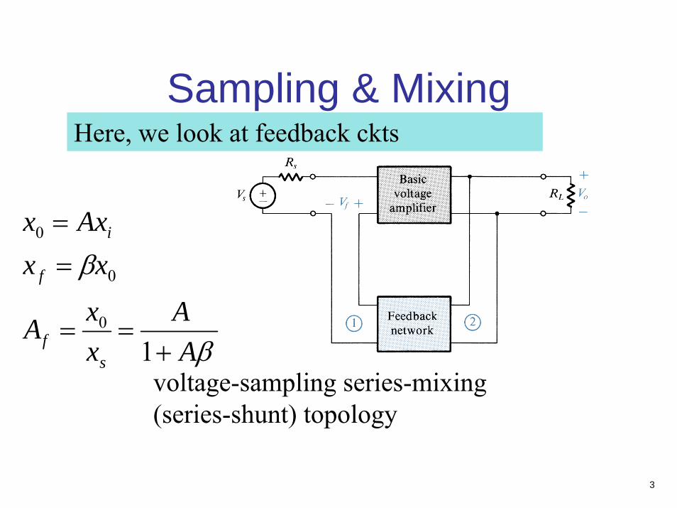
Sampling & MixingHere, we look at feedback ckts
voltage-sampling series-mixing (series-shunt) topology
β
β
AA
xxA
xxAxx
sf
f
i
+==
==
10
0
0

4
current-sampling shunt-mixing (shunt-series) topology
5
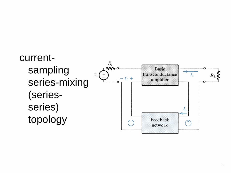
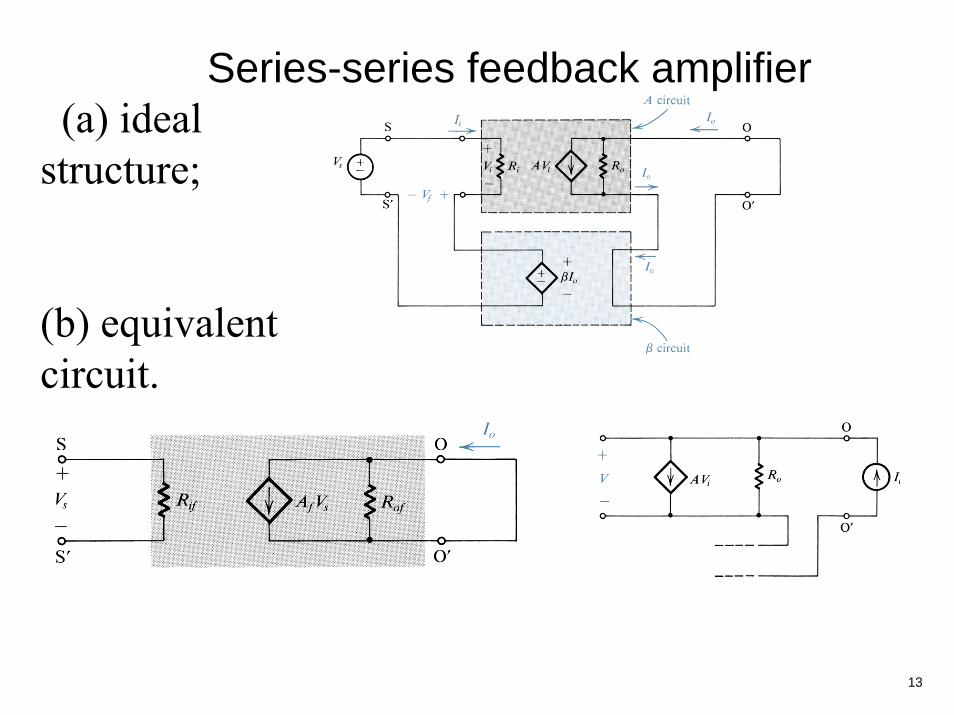
current-sampling series-mixing (series-series) topology
6
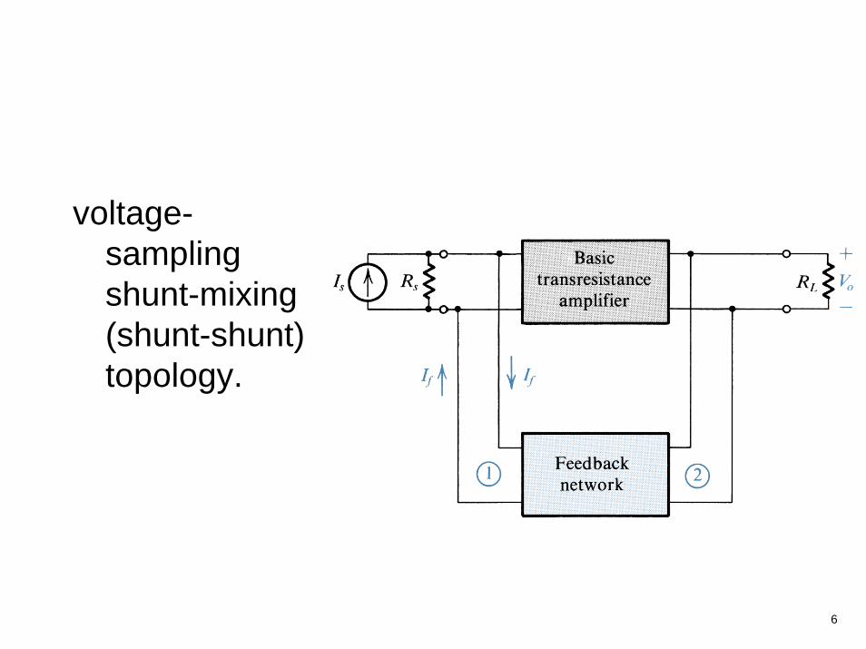
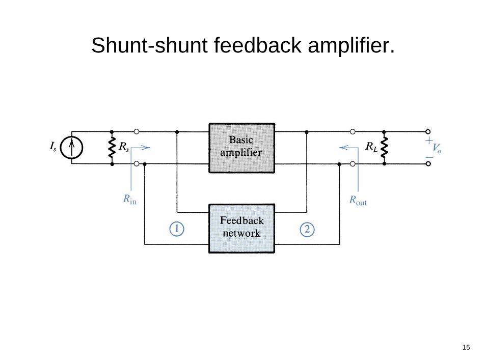
voltage-sampling shunt-mixing (shunt-shunt) topology.
7
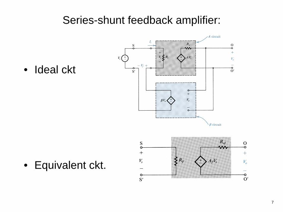
Series-shunt feedback amplifier:
• Ideal ckt
• Equivalent ckt.

8
Measuring the output resistance of the voltage-sampling
series-mixing (series-shunt) topology
feedback amplifier of Rof ≡ Vt/I.

9
Derivation of the A circuit and β circuit for the series-shunt feedback amplifier.
(a) Block diagram of a practical series-shunt feedback amplifier.
(b) The circuit in (a) with the feedback network represented by its hparameters.
(c) The circuit in (b) after neglecting h21.
10
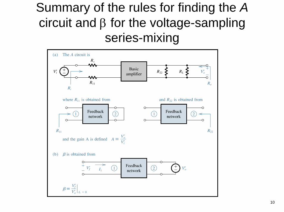
Summary of the rules for finding the Acircuit and β for the voltage-sampling
series-mixing
11
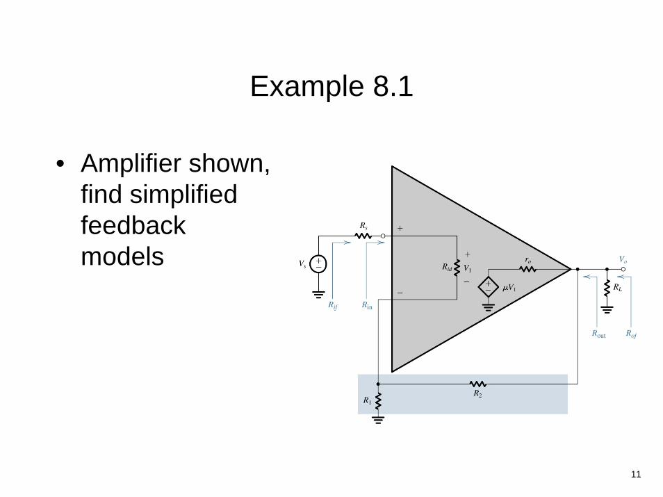
Example 8.1
• Amplifier shown, find simplified feedback models
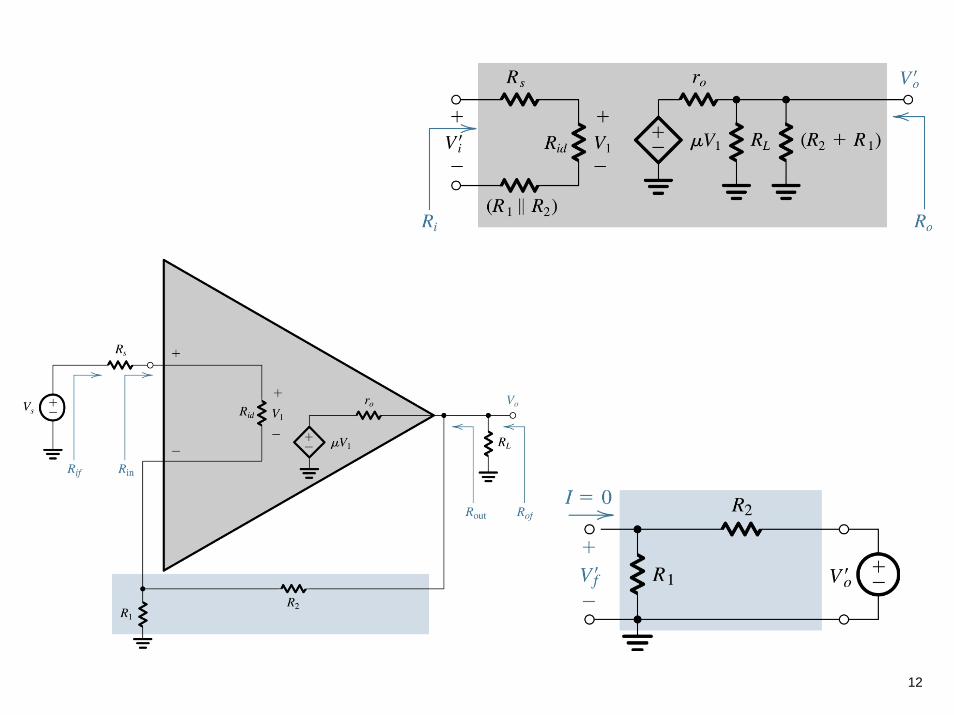
12
13
(a) ideal structure;
(b) equivalent circuit.
Series-series feedback amplifier

14
Ideal structure for the shunt-shunt feedback amplifier.
15
Shunt-shunt feedback amplifier.

16
Finding the Acircuit and β for the voltage-sampling shunt-mixing (shunt-shunt) case.
17
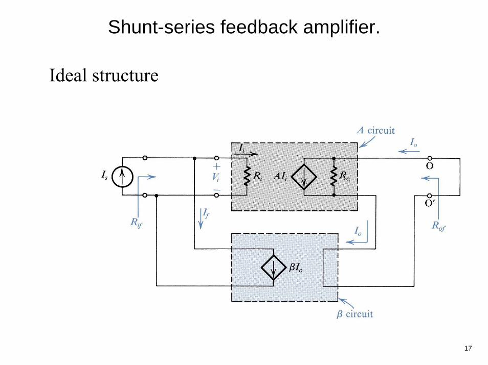
Ideal structure
Shunt-series feedback amplifier.
18
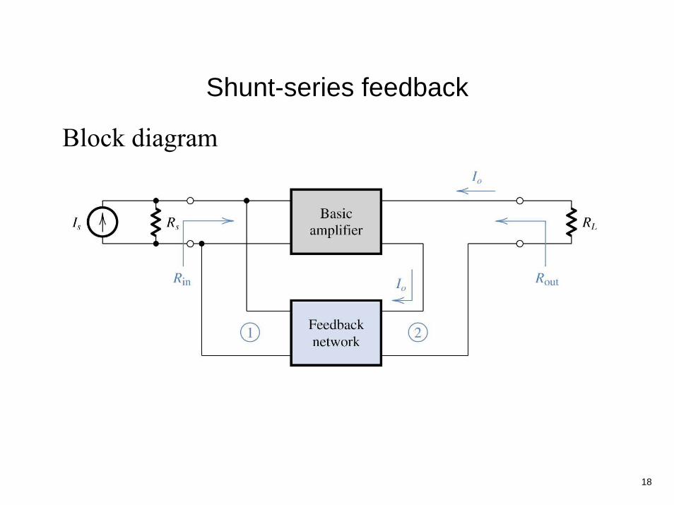
Block diagram
Shunt-series feedback
19
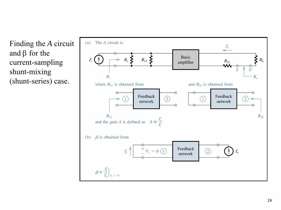
Finding the A circuit and β for the current-sampling shunt-mixing (shunt-series) case.

Amplifier instability
20
)()(1)()(
180180
180180 ωβω
ωωjjA
jAjAf +=
999.0)()( 180180 −=ωβω jjA
A(jώ180) =999β(jώ180) = -0.001
)sin(1.0)( 180ttxi ω= )sin(100)( 180ttxo ω=
)sin(1.0)( 180ttx f ω−=

21
Bode plot for the loop gain Aβ illustrating the definitions of the gain and phase margins.
22
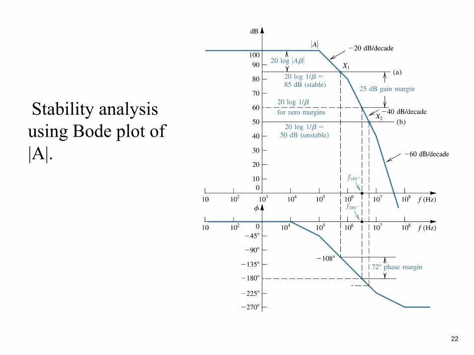
Stability analysis using Bode plot of |A|.

23
Frequency compensation for β = 10-2.
• The response labeled A’ is obtained by introducing an additional pole at fD.
•The A” response is obtained by moving the original low-frequency pole to f’D.