FEEDBACK, STABILITY and OSCILLATORSeelinux.ee.usm.maine.edu/courses/ele343/343 Class...
28
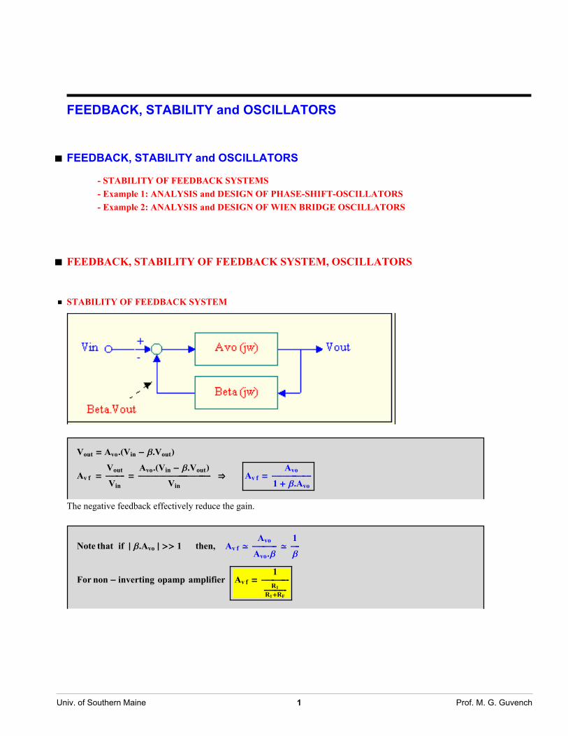
FEEDBACK, STABILITY and OSCILLATORS à FEEDBACK, STABILITY and OSCILLATORS - STABILITY OF FEEDBACK SYSTEMS - Example 1: ANALYSIS and DESIGN OF PHASE-SHIFT-OSCILLATORS - Example 2: ANALYSIS and DESIGN OF WIEN BRIDGE OSCILLATORS à FEEDBACK, STABILITY OF FEEDBACK SYSTEM, OSCILLATORS ü STABILITY OF FEEDBACK SYSTEM V out = A vo .HV in -b.V out L A vf = V out ÄÄÄÄÄÄÄÄÄÄÄÄ V in = A vo .HV in -b.V out L ÄÄÄÄÄÄÄÄÄÄÄÄÄÄÄÄÄÄÄÄÄÄÄÄÄÄÄÄÄÄÄÄ ÄÄÄÄÄÄÄÄÄÄÄÄÄÄÄÄ ÄÄÄÄÄÄÄ V in fi A vf = A vo ÄÄÄÄÄÄÄÄÄÄÄÄÄÄÄÄ ÄÄÄÄÄÄÄÄÄÄÄ 1 +b.A vo The negative feedback effectively reduce the gain. Note that if » b.A vo » >> 1 then, A vf > A vo ÄÄÄÄÄÄÄÄÄÄÄÄÄÄÄÄ A vo . b > 1 ÄÄÄÄÄ b For non - inverting opamp amplifier A vf = 1 ÄÄÄÄÄÄÄÄÄÄÄÄÄÄÄÄÄÄÄ R 1 ÄÄÄÄÄÄÄÄÄÄÄÄÄÄ R 1 +R F Univ. of Southern Maine 1 Prof. M. G. Guvench
-
Upload
truongnhan -
Category
Documents
-
view
228 -
download
0
Transcript of FEEDBACK, STABILITY and OSCILLATORSeelinux.ee.usm.maine.edu/courses/ele343/343 Class...
FEEDBACK, STABILITY and OSCILLATORS
à FEEDBACK, STABILITY and OSCILLATORS
- STABILITY OF FEEDBACK SYSTEMS- Example 1: ANALYSIS and DESIGN OF PHASE-SHIFT-OSCILLATORS- Example 2: ANALYSIS and DESIGN OF WIEN BRIDGE OSCILLATORS
à FEEDBACK, STABILITY OF FEEDBACK SYSTEM, OSCILLATORS
ü STABILITY OF FEEDBACK SYSTEM
Vout = Avo.HVin - b.VoutLAv f =
VoutÄÄÄÄÄÄÄÄÄÄÄÄÄÄÄVin
=Avo.HVin - b.VoutLÄÄÄÄÄÄÄÄÄÄÄÄÄÄÄÄÄÄÄÄÄÄÄÄÄÄÄÄÄÄÄÄÄÄÄÄÄÄÄÄÄÄÄÄÄÄÄÄÄÄÄÄÄÄÄÄÄ
Vinfi Av f =
AvoÄÄÄÄÄÄÄÄÄÄÄÄÄÄÄÄÄÄÄÄÄÄÄÄÄÄÄÄÄÄÄ1 + b.Avo
The negative feedback effectively reduce the gain.
Note that if » b.Avo » >> 1 then, Av f >Avo
ÄÄÄÄÄÄÄÄÄÄÄÄÄÄÄÄÄÄÄAvo.b
>1
ÄÄÄÄÄÄÄb
For non - inverting opamp amplifier Av f =1
ÄÄÄÄÄÄÄÄÄÄÄÄÄÄÄÄÄÄÄÄÄÄR1ÄÄÄÄÄÄÄÄÄÄÄÄÄÄÄÄÄÄR1+RF
Univ. of Southern Maine 1 Prof. M. G. Guvench

Phase at w Ø ¶ (number of zeros -number of poles) . 90°
Even if Avo (0) may be very large , at high frequencies » AvoHjwL » can become very small; making the approximation aboveinvalid.
Av f HjwL =Avo HjwL
ÄÄÄÄÄÄÄÄÄÄÄÄÄÄÄÄÄÄÄÄÄÄÄÄÄÄÄÄÄÄÄÄÄÄÄÄÄÄÄÄÄÄÄÄÄÄÄÄÄÄÄÄÄÄÄÄÄÄÄ1 + Avo HjwL.b HjwL
For DC, the negative feedback results in a (+) sign in the denominator. Therefore, » Av f HjwL » will always be smaller than» AvoHjwL |.But, if the inputs are reversed or somehow AvoHjwL.bHjwL changes its sign, the feedback becomes positive, the denomina-tor can become < |1|, therefore, Av f with feedback becomes even greater than Avo of the operational amplifier.
Interesting Point: Denominator ª 0 fl "Instability" fl Oscillations
Conditions for Instability HOscillationsL 1 + Av HjwL.b HjwL ∫ 0
Equivalently J Re @1 + Avo HjwL.b HjwLD = 0Im @1 + Avo HjwL.b HjwLD = 0
a. 1 + Re @Avo HjwL.b HjwLD = 0 or Re @Avo HjwL.b HjwLD = -1b. Im @HAvo HjwL.b HjwLD = 0 fi Phase of HAvo.bL = 0, ¡180, ¡360
Note that, it is impossible to make Re @1 + Avo HjwL.b HjwLD = 0 for phase = 0 or ¡ 360
ELE 343 FeedbackStabilityOscillatorsActivefilters-Y.
Univ. of Southern Maine 2 Prof. M. G. Guvench

For instability :J [email protected] = ¡180 °[email protected] = -1 N or, J [email protected] = ¡180 °» Avo.b » = 1 N
ELE 343 FeedbackStabilityOscillatorsActivefilters-Y.
Univ. of Southern Maine 3 Prof. M. G. Guvench

Stable system since » Avo.b | < 1 at the critical frequency(2) which satisfies the phase condition.
Definitions/Conditions for Stability:
Loop Gain = Avo.b Worst case: b=1 for passive circuits
ELE 343 FeedbackStabilityOscillatorsActivefilters-Y.
Univ. of Southern Maine 4 Prof. M. G. Guvench

fM (Phase Margin) > 30 ~ 60° - 70° for a good internally compensated opamp
Gain Margin > 10 dB
xxxxxxxxxxxxxxxxxxxxx
OSCILLATOR ª Unstable but at a unique frequency so that it generates a sine wave with minimal distortion and minimaldrift of oscillation frequency.
ELE 343 FeedbackStabilityOscillatorsActivefilters-Y.
Univ. of Southern Maine 5 Prof. M. G. Guvench

à Example 1: ANALYSIS and DESIGN OF PHASE-SHIFT-OSCILLATORS
Note that for an oscillator to oscillate it does not need a signal, therefore, the signal input shown in the block diagrams can be eliminated.
Amplifier Gain = Av Beta HjωL = β Hjω )
b (jw) circuit
Beta HjwL = b HjwL =V2 HjwLÄÄÄÄÄÄÄÄÄÄÄÄÄÄÄÄÄÄÄÄÄÄÄÄV1 HjwL
ELE 343 FeedbackStabilityOscillatorsActivefilters-Y.
Univ. of Southern Maine 6 Prof. M. G. Guvench

Educated conclusion: use higher number of RC's than 3 to achieve higher slope for better frequency stability.
@VD = @ZD * @ID V is known, I is unknown stimuli
ikjjjjjjj V1
00
y{zzzzzzz =
ikjjjjjjjjjjjjjjj
R + 1ÄÄÄÄÄÄÄÄÄÄÄÄj wC -R 0
-R 2 R + 1ÄÄÄÄÄÄÄÄÄÄÄÄj wC -R
0 -R 2 R + 1ÄÄÄÄÄÄÄÄÄÄÄÄj wC
y{zzzzzzzzzzzzzzz ikjjjjjjj I1
I2
I3
y{zzzzzzzand output voltage, V2 = R.I3
One can apply Cramer's Rule to solve for I3 and the output voltage V2= R. I3 . In Mathematica the same calculation canbe done by using linear solver which yields { I1 , I2 , I3} and pick out I3 , the third term from the list, and multiply it byR, as done below.
V2 = ExpandAllAR ∗TakeALinearSolveAikjjjjjjjjjjjjjjR + 1
j ω C−R 0
−R 2 R + 1j ω C
−R
0 −R 2 R + 1j ω C
y{zzzzzzzzzzzzzz, ikjjjjjjj V100 y{zzzzzzzE, 83<E ê.
ω −>1
j R C yE
99 V11 + 6 y + 5 y2 + y3
==V1
1 + 6 y + 5 y2 + y3ê. y −>
1
j ω R C
V11 + 1
C3 j3 R3 ω3 + 5C2 j2 R2 ω2 + 6
C j R ω
Rearrange V2 = V1 1H1 − 5
ω2 R2 C2L + 1
jω R C H6 − 1
ω2 R2 C2L
For the phase to reach 0 or ¡180° imaginary term should disappear,
ELE 343 FeedbackStabilityOscillatorsActivefilters-Y.
Univ. of Southern Maine 7 Prof. M. G. Guvench

Therefore, 6 −1
ω2 R2 C2= 0 ⇒ ω 0 = $%%%%%%%%%%%%%%%%%%1
6 R2 C2
Then,V2
V1=ikjjjjjj 1
1 − 5. 1ω2 R2 C2
y{zzzzzzω2 = 16 R2 C2
=1
1 − 5.6=
1
1 − 30=
1
−29
If Avo ≥ ikjjj 1
βy{zzzω 0
2= 16 R2 C2
then oscillations will start and grow at ω0.
Summary:
If » Avo » ¥ 29, If Avo < 0 (i.e. inverting)
Oscillations will start and grow up at ω0 =1è!!!!6 RC
Av f =Avo
1 + β HjωL Avo=
Avo
1 − 1= ∞
ELE 343 FeedbackStabilityOscillatorsActivefilters-Y.
Univ. of Southern Maine 8 Prof. M. G. Guvench

à Example 2: ANALYSIS and DESIGN OF WIEN BRIDGE OSCILLATORS
ELE 343 FeedbackStabilityOscillatorsActivefilters-Y.
Univ. of Southern Maine 9 Prof. M. G. Guvench

ELE 343 FeedbackStabilityOscillatorsActivefilters-Y.
Univ. of Southern Maine 10 Prof. M. G. Guvench

Beta = β HjωL =Zb
Za + Zb=
11Rb
+jω CbIRa + 1jω Ca
M + J 11Rb
+jω CbN
=1IRa + 1
jω CaM I 1
Rb+ jω CbM + 1
=1A Ra
Rb+ j Iω Ra Cb − 1
ω Rb CaM + Cb
Ca+ 1E
=1I Ra
Rb+ Cb
Ca+ 1M + j Iω Ra Rb − 1
ω Rb CaM
When ω2 = ω02 =1
Ra Rb Ca Cbthe imaginary term disappears
β Hj ω0L =1
RaRb
+ CbCa
+ 1
If H+L feedback is provided Av f =Avo
1 − β HjωL Avo
at ω = ω0 Av f Hjω0 L Avo
1 − β Hjω0L Avo
or Av f Hjω0 L ∞ if Avo ≥1
β Hjω0L =Ra
Rb+Cb
Ca+ 1
For Ca = Cb = C , Ra = Rb = R Avo ≥ 3
ELE 343 FeedbackStabilityOscillatorsActivefilters-Y.
Univ. of Southern Maine 11 Prof. M. G. Guvench

Wien - Bridge Oscillator
ikjj Rf
R1+ 1y{zz ≥
Ra
Rb+Cb
Ca+ 1
Amplifier Design :
Condition 1 : Zin >> Zab where Zab = HZa êê ZbLω = ω0
Condition 2 : Avo > ikjjj 1
β
y{zzzω = ω0
In order to control the amplitude(1) Small Signal Gain > minimum needed for oscillation, (2) Average gain reduces and becomes less than ( 1
βM
ω= ω0
at the amplitude of oscillations it is required to stabilize.
Amplifer Chs. with Saturating Gain
ELE 343 FeedbackStabilityOscillatorsActivefilters-Y.
Univ. of Southern Maine 12 Prof. M. G. Guvench

Inverting Amplifier with Gain Saturation
Low amplitudes RF = RF1Mid amplitudes RF ≡ RF1 êê RF2High amplitudes RF = RF1 êê RF2 êê RF3Av f =
ikjjjjjjj 1β
1 + 1β Av
y{zzzzzzz > 1
β
ELE 343 FeedbackStabilityOscillatorsActivefilters-Y.
Univ. of Southern Maine 13 Prof. M. G. Guvench

H b.Av L ¥ 1 b.Av > 1 b.Av ª 1 HAvLLarge
Signal
≤ HAvLSmallsignal
ELE 343 FeedbackStabilityOscillatorsActivefilters-Y.
Univ. of Southern Maine 14 Prof. M. G. Guvench
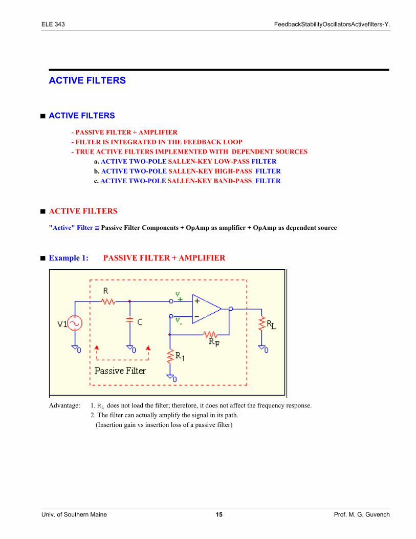
ACTIVE FILTERS
à ACTIVE FILTERS
- PASSIVE FILTER + AMPLIFIER- FILTER IS INTEGRATED IN THE FEEDBACK LOOP- TRUE ACTIVE FILTERS IMPLEMENTED WITH DEPENDENT SOURCES
a. ACTIVE TWO-POLE SALLEN-KEY LOW-PASS FILTERb. ACTIVE TWO-POLE SALLEN-KEY HIGH-PASS FILTERc. ACTIVE TWO-POLE SALLEN-KEY BAND-PASS FILTER
à ACTIVE FILTERS
"Active" Filter ∫ Passive Filter Components + OpAmp as amplifier + OpAmp as dependent source
à Example 1: PASSIVE FILTER + AMPLIFIER
Advantage: 1. RL does not load the filter; therefore, it does not affect the frequency response.2. The filter can actually amplify the signal in its path. (Insertion gain vs insertion loss of a passive filter)
ELE 343 FeedbackStabilityOscillatorsActivefilters-Y.
Univ. of Southern Maine 15 Prof. M. G. Guvench

observe that ω− 3 dB = 1R Thevenin. C
≠ 1R C
and depends on loading resistance RL.
At higher frequencies, frequency response of "real opamp" will alter the frequency response of the active filter.* Note that the danger of instability at the frequency where phase angle ª 180 °* If the opamp is internally frequency compensated it can introduce no more than 90° phase while its gain is still greaterthan "0 dB". This implies that:Overall filter will never have a gain greater than 0 dB when phase = -180°ï stable.
ELE 343 FeedbackStabilityOscillatorsActivefilters-Y.
Univ. of Southern Maine 16 Prof. M. G. Guvench

à Example 2: FILTER IS INTEGRATED IN THE FEEDBACK LOOP
If the opamp has wide enough GBW and low frequency gain;
Avf HjωL =∆ Vout
Vin=
Avo
1 + β Avo>
1
β HjωLThis has the effect of Low Pass ö Low Reject (High Pass)
High Pass ö High RejectBand Pass ö Band Reject
A Good "Band Reject" Filter
Remark: A good Low / High / Band Reject actually reduces the signal in the reject band significantly, i.e. gain << 1.
ELE 343 FeedbackStabilityOscillatorsActivefilters-Y.
Univ. of Southern Maine 17 Prof. M. G. Guvench

à Example 3: TRUE ACTIVE FILTERS IMPLEMENTED WITH DEPENDENT SOURCESa. ACTIVE TWO-POLE SALLEN-KEY LOW-PASS FILTERb. ACTIVE TWO-POLE SALLEN-KEY HIGH-PASS FILTERc. ACTIVE TWO-POLE SALLEN-KEY BAND-PASS FILTER
a. ACTIVE TWO-POLE SALLEN-KEY LOW-PASS FILTER
Equivalent circuit:
ELE 343 FeedbackStabilityOscillatorsActivefilters-Y.
Univ. of Southern Maine 18 Prof. M. G. Guvench

Node Equations:
ELE 343 FeedbackStabilityOscillatorsActivefilters-Y.
Univ. of Southern Maine 19 Prof. M. G. Guvench

ikjjjj VinR1
+ VO s C1
0
y{zzzz = JHG1 + G2 + sC1L −G2−G2 HG2 + sC2LN JV1
V0N
ikjjjj VinR1
0
y{zzzz = JHG1 + G2 + sC1L −HG2 + sC1LH−G2L HG2 + sC2L N JV1V0N
Using Cramer' s Rule to getVOVinR1
V0VinR1
=1I VinR1
M .
DetAikjjjjHG1 + G2 + sC1L VinR1H−G2L 0
y{zzzz EDetAJHG1 + G2 + sC1L −HG2 + sC1LH−G2L HG2 + sC2L N E
=1I VinR1
M .−I Vin
R1M H−G2LHG1 + G2 + sC1L HG2 + sC2L − G2 HG2 + sC1L
VO
Vin= H HsL =
G1.G2
s2 C1 C2 + sC1 G2 + sC2 HG1 + G2L + G2 HG1 + G2L − G22 − G2 sC1
=G1.G2
s2 C1 C2 + sC2 HG1 + G2L + G1.G2
=
1HR1 C1L HR2 C2Ls2 + s I 1
R1 C1+ 1
R2 C1M + I 1
R1 C1M I 1
R2 C2M
Rename :1
R1 C1 R2 C2= ω0
2 ikjjj 1
R1 C1+
1
R2 C1
y{zzz = 2 ζ ω0
H HsL =ω02
s2 + 2 ζω0 s + ω02 No inductor!
The response of this circuit is similar to the response of an RLC - Low Pass passive filter shown below. Except that thereis no need to employ bulky, lossy and expensive inductors to implement it .
ELE 343 FeedbackStabilityOscillatorsActivefilters-Y.
Univ. of Southern Maine 20 Prof. M. G. Guvench
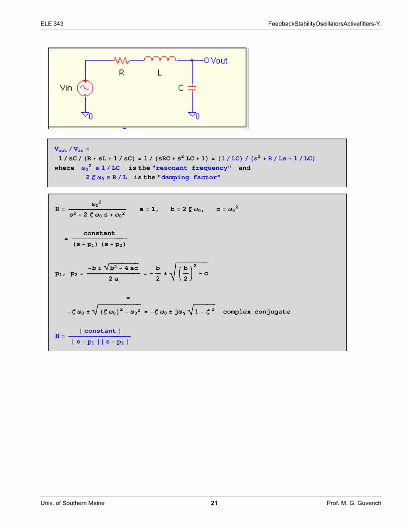
Vout ê Vin =
1êsCêHR + sL + 1êsCL = 1êHsRC + s2 LC + 1L = H1êLCLêHs2 + R êLs + 1êLCLwhere ω02 ≡ 1êLC is the "resonant frequency" and
2 ζ ω0 ≡ R êL is the "damping factor"
H =ω02
s2 + 2 ζ ω0 s + ω02a = 1, b = 2 ζ ω0, c = ω02
=constantHs − p1L Hs − p2L
p1, p2 =−b ±
è!!!!!!!!!!!!!!!!!!!b2 − 4 ac
2 a= −
b
2± $%%%%%%%%%%%%%%%%%%%%ikjj b
2
y{zz2 − c
=
−ζ ω0 ±"###########################Hζ ω0L2 − ω02 = −ζ ω0 ± jω0
"##############1 − ζ 2 complex conjugate
H =» constant »» s − p1 »» s − p2 »
ELE 343 FeedbackStabilityOscillatorsActivefilters-Y.
Univ. of Southern Maine 21 Prof. M. G. Guvench
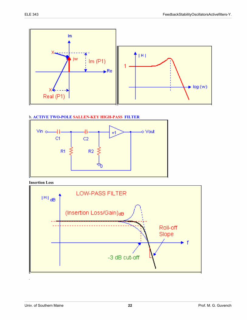
b. ACTIVE TWO-POLE SALLEN-KEY HIGH-PASS FILTER
Insertion Loss
ELE 343 FeedbackStabilityOscillatorsActivefilters-Y.
Univ. of Southern Maine 22 Prof. M. G. Guvench

ELE 343 FeedbackStabilityOscillatorsActivefilters-Y.
Univ. of Southern Maine 23 Prof. M. G. Guvench
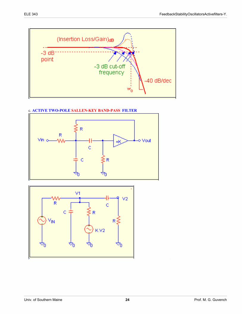
c. ACTIVE TWO-POLE SALLEN-KEY BAND-PASS FILTER
ELE 343 FeedbackStabilityOscillatorsActivefilters-Y.
Univ. of Southern Maine 24 Prof. M. G. Guvench
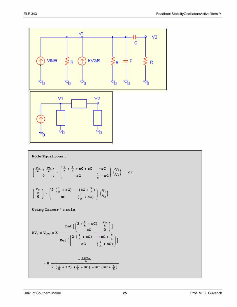
Node Equations :
ikjjjj VINR
+ KV2R
0
y{zzzz =ikjjjjjj 1
R+ 1
R+ sC + sC −sC
−sC 1R
+ sC
y{zzzzzz JV1V2N or
ikjjjj VINR
0
y{zzzz =ikjjjjjj2 H 1
R+ sCL −HsC + K
RL
−sC H 1R
+ sCL y{zzzzzz JV1V2N
Using Cramer' s rule,
KV2 = VOUT = K
DetAikjjjj2 H 1R
+ sCL VINR
−sC 0
y{zzzzEDetAikjjjjjj2 H 1
R+ sCL −HsC + K
R
−sC H 1R
+ sCLy{zzzzzzE= K
+ s C VINR
2 H 1R
+ sCL H 1R
+ sCL − sC HsC + KRL
ELE 343 FeedbackStabilityOscillatorsActivefilters-Y.
Univ. of Southern Maine 25 Prof. M. G. Guvench

VOUT
VIN= K
sCR
2 HsCL2 + 4 H sCRL + 2 H 1
RL2 − HsCL2 − sC
R K
after dividing by C2,
H HsL = K
sCRHsCL2 + H4 − KL sC
R+ 2 H 1
RL2
H HsL = K
sR C
s2 + H4 − KL 1R C´̈ ¨¨¨̈ ¨¨¨̈ ≠ ƨ¨¨¨̈ ¨̈ ¨
s
2 γ = 2 ζ ω n
+ J è!!!!2
R CN2
´̈ ¨¨¨̈¨≠ ƨ¨̈ ¨̈ω n
2
ωn =
è!!!!2
R Cω n = ω 0
2 + γ2
The damping factor : ζ =H4 − KL 1
R C
2 è!!!!2
R C
=H4 − KL2 è!!!!2
Poles = −γ ± jω 0 Resonance is at ω = ω 0
BandWidth = BW = ω 2 − ω 1 = ω 0 + γ − Hω 0 − γL = 2 γ
Quality Factor of a Resonant Circuit : Q =ω peak
BW>
ω 0
2 ζ=
è!!!!2
4 − K
ELE 343 FeedbackStabilityOscillatorsActivefilters-Y.
Univ. of Southern Maine 26 Prof. M. G. Guvench

» Hmax » =K jω
RCH+jωL2 + H 4−KR C
L jω + Hω0L2 = K 1
4 − K=
Kè!!!!2
è!!!!2
4 − K= K
Qè!!!!2
K 4 » H »max ∞ unstable! Oscillator
ELE 343 FeedbackStabilityOscillatorsActivefilters-Y.
Univ. of Southern Maine 27 Prof. M. G. Guvench

ELE 343 FeedbackStabilityOscillatorsActivefilters-Y.
Univ. of Southern Maine 28 Prof. M. G. Guvench