
Feed Mill Info
33
California Pellet Mill Co. 1 The Pelleting Process For many years, pelleting was considered an art, a process involving imprecise measurement, uncertain results, and that undefinable quality of feel . This so-called “art” of pelleting came about in an environment lacking the understanding of the effects occurring when the differing characteristics of feed ingredients are subjected to the pelleting processes of heat, moisture, and pressure. No excuse, however, exists today for the uni nformed pellet mill operator. The science of grain processing has now reached a point that, by knowing the characteristics of the feed (moisture, content, fiber, etc.) and using machinery with accurate measurements, the guesswork has been removed from pelleting. As a result, much more is required of the pellet mill operator in the way of knowledge and ability. The skill of the pellet mill operato r, through his ability or mistakes, influences plant profitability. Pellet mill operators have a vitally impo rtant role in the manufacture of animal feed. They should recognize this responsibility and the great contribution they make to an efficient feed plant. INTRODUCTION TO PELLETING The Purpose of Pelleting Pelleted feeds have been defined as “agglomerated feeds formed by extruding individual ingredients or mixtures by compacting and forcing through die openings by any mechanical process”. Basically, the purpose of pellet ing is to take a finely divided, sometimes dusty, unpalatable and difficult-to-handle feed material and, by using heat, moisture and pressure, form it into larger particles. These larger particles are easier to handle, more palatable and usually result in improved feeding results when compared to the unpelleted feed. Pellets are generally formed with diameters from 10/64” to 48/64” and will be somewhat longer than the diameter. A small part of the production of large pellets, 32/64” and above in diame ter, is produced in other than cylindrical shapes; they may be triangular, square or oval and, in some cases, may exceed the maximum dimension indicated above. The largest diameter usually found is rarely greater than 1-1/4” to 1-3/8”. In most cases where particle size s smaller than 10/64” are desired, it has been found to be more satisfactory from the standpoint of economics to produce a 10/64” or 12/64” pellet and reduce it into the desired particle size by means of crumbling. Almost all livestock feeders agree that animals make better gains on pelleted feed than a meal ration. The most logical reasons are that (a) the heat generated in conditioning and pell eting make the feedstuffs more digestible by breaking down the starches, (b) the pellet simply puts the feed in a concentrated form, and (c) pelleting mini mizes waste during the eating process. When pelleted feed is fed, each animal receives a well-balanced diet by preventing the animal from picking and choosing between ingredie nts. Tests have shown that most animals, if given the choice between the same feed in pellet or mash form will prefer the pellets. By combining moisture, heat and pressure on feed ingredients, a degree of gelatinization is produced which allows animals and poultry to better utilize the nutrients in these ingredients.
Transcript of Feed Mill Info
8/3/2019 Feed Mill Info
http://slidepdf.com/reader/full/feed-mill-info 1/33
California Pellet Mill Co.
1
The Pelleting Process
For many years, pelleting was considered an art, a process involving imprecise measurement,uncertain results, and that undefinable quality of feel. This so-called “art” of pelleting cameabout in an environment lacking the understanding of the effects occurring when the differingcharacteristics of feed ingredients are subjected to the pelleting processes of heat, moisture, andpressure. No excuse, however, exists today for the uninformed pellet mill operator.
The science of grain processing has now reached a point that, by knowing the characteristics ofthe feed (moisture, content, fiber, etc.) and using machinery with accurate measurements, theguesswork has been removed from pelleting. As a result, much more is required of the pelletmill operator in the way of knowledge and ability. The skill of the pellet mill operator, throughhis ability or mistakes, influences plant profitability.
Pellet mill operators have a vitally important role in the manufacture of animal feed. Theyshould recognize this responsibility and the great contribution they make to an efficient feed
plant.
INTRODUCTION TO PELLETING
The Purpose of Pelleting
Pelleted feeds have been defined as “agglomerated feeds formed by extruding individualingredients or mixtures by compacting and forcing through die openings by any mechanicalprocess”. Basically, the purpose of pelleting is to take a finely divided, sometimes dusty,unpalatable and difficult-to-handle feed material and, by using heat, moisture and pressure,form it into larger particles. These larger particles are easier to handle, more palatable and
usually result in improved feeding results when compared to the unpelleted feed.
Pellets are generally formed with diameters from 10/64” to 48/64” and will be somewhat longerthan the diameter. A small part of the production of large pellets, 32/64” and above in diameter,is produced in other than cylindrical shapes; they may be triangular, square or oval and, in somecases, may exceed the maximum dimension indicated above. The largest diameter usually foundis rarely greater than 1-1/4” to 1-3/8”. In most cases where particle sizes smaller than 10/64” aredesired, it has been found to be more satisfactory from the standpoint of economics to produce a10/64” or 12/64” pellet and reduce it into the desired particle size by means of crumbling.
Almost all livestock feeders agree that animals make better gains on pelleted feed than a mealration. The most logical reasons are that (a) the heat generated in conditioning and pelleting
make the feedstuffs more digestible by breaking down the starches, (b) the pellet simply puts thefeed in a concentrated form, and (c) pelleting minimizes waste during the eating process. Whenpelleted feed is fed, each animal receives a well-balanced diet by preventing the animal frompicking and choosing between ingredients. Tests have shown that most animals, if given thechoice between the same feed in pellet or mash form will prefer the pellets.
By combining moisture, heat and pressure on feed ingredients, a degree of gelatinization isproduced which allows animals and poultry to better utilize the nutrients in these ingredients.
8/3/2019 Feed Mill Info
http://slidepdf.com/reader/full/feed-mill-info 2/33
California Pellet Mill Co.
2
Feed conversion will be improved. These advantages are particularly noticeable in the broilerindustry.
The feeding merits of pelleted feeds over the mash form have been repeatedly demonstrated inthe feeding of swine. One state college reported the results of an eight week swine feeding test inwhich pelleted feed performance was compared against the same feed in mash form. This test
gave the following results:
All animals, on the average, consumed the same amount of feed (5.06 lb. per day of pellets vs.5.02 lb. per day of mash), yet the pellet fed pigs gained a quarter of a pound per day more weightthan did the mash fed animals (1.76 lb. vs. 1.54 lb. of gain per day). Since the pellet fed hogsgained more while eating the same amount, it is evident that pelleting causes the feed to beutilized more efficiently by these animals. This is shown in the comparison of the averageamount of feed required for each pound of gain. The pellet fed hogs consumed 2.87 lb. of feedper pound of gain while the mash fed hogs needed 3.27 lb. to make a pound of weight gain.Pellet fed hogs not only gain faster but they do it with less feed for each pound of weightincrease.
Pelleting prevents the segregation of ingredients in a mixing, handling or feeding process. Byfeeding a pelleted feed, the animal is more apt to receive a totally mixed ration than one that hasseparated through these processes. It also prevents waste. Bulk density is increased, whichenhances storage capabilities of most bulk facilities. Shipping facilities are also increased,thereby reducing transportation costs. This is particularly evident in such fibrous ingredients asalfalfa, gluten feed, oat hulls, rice, bran, etc.. A better flow and handling characteristic of pelletsis one of the least mentioned advantages but probably the most important, particularly as itrelates to dairy farmers.
In 1978, there were 9,977 feed mills registered with FDA producing 78.2 million tons of feedannually; about 60% is pelleted. Not all feed mills, of course, are equipped to pellet feeds. In1958, these mills produced 40 million tons of feed and about 55% was pelleted. In 1968, about70% of all commercial poultry feed produced in the United States was pelleted. In the Midwest,almost 80% of all manufactured feed is pelleted, crumblized or cubed.
The process of producing feed pellets can roughly be described as a plastic molding operation ofthe extrusion type. Feed ingredients are made up of various compounds such as proteins, acids,sugars, fibers, and minerals. These products can be softened (conditioned) by the addition ofheat and water. When sufficiently controlled compression is applied to the “conditioned” feedingredients, they will form a dense mass, shaped to conform to the die against which they arepressed. When the heat and moisture is again withdrawn (dried and cooled) as to withstandmoderately rough handling without excessive breakage and has retained or enhanced itsnutritive value.
In modern feed mills, the ingredients are usually stored in bins above a weighing system
composed of one or more scales. Those ingredients which are of coarse texture, such as wholegrains and other fibrous materials, are ground into a fine meal to facilitate the pelleting andmixing process. Weighted quantities of each ingredient (either as a batch or continuously) arethoroughly mixed (either in a batch mixer of a continuous flow mixing unit) and then conveyedto a bin above the pellet mill. Some manufacturers have installed systems to grind all of theirpremixed materials prior to entering the pellet mill. Data is not available which indicates this hasbeen an advantage or disadvantage on a consistent basis as far as durability is concerned.
8/3/2019 Feed Mill Info
http://slidepdf.com/reader/full/feed-mill-info 3/33
California Pellet Mill Co.
3
Terms Used in Pelleting
The following terms are often used to measure the efficiency and quality of pellet mill operation.
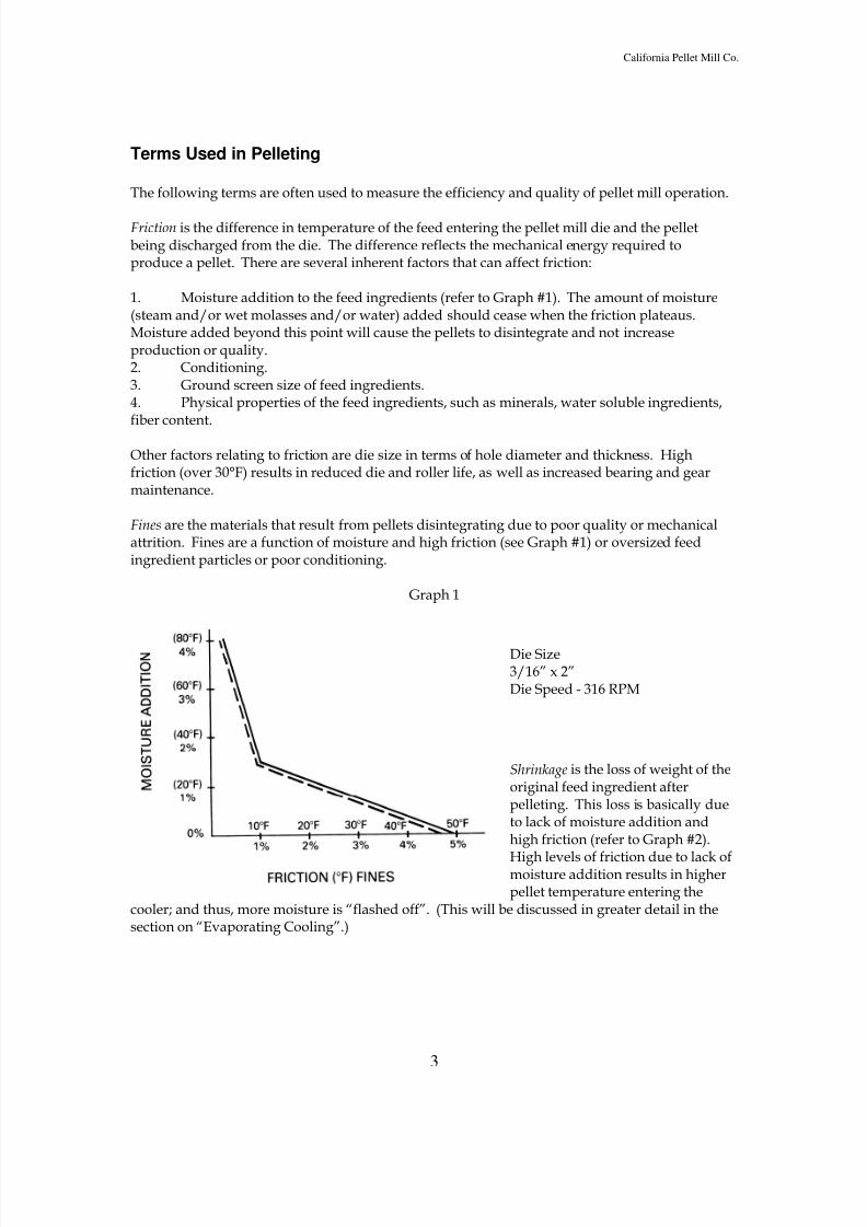
Friction is the difference in temperature of the feed entering the pellet mill die and the pelletbeing discharged from the die. The difference reflects the mechanical energy required toproduce a pellet. There are several inherent factors that can affect friction:
1. Moisture addition to the feed ingredients (refer to Graph #1). The amount of moisture(steam and/or wet molasses and/or water) added should cease when the friction plateaus.Moisture added beyond this point will cause the pellets to disintegrate and not increaseproduction or quality.2. Conditioning.3. Ground screen size of feed ingredients.4. Physical properties of the feed ingredients, such as minerals, water soluble ingredients,fiber content.
Other factors relating to friction are die size in terms of hole diameter and thickness. Highfriction (over 30°F) results in reduced die and roller life, as well as increased bearing and gearmaintenance.
Fines are the materials that result from pellets disintegrating due to poor quality or mechanicalattrition. Fines are a function of moisture and high friction (see Graph #1) or oversized feedingredient particles or poor conditioning.
Graph 1
Die Size3/16” x 2”Die Speed - 316 RPM
Shrinkage is the loss of weight of theoriginal feed ingredient afterpelleting. This loss is basically dueto lack of moisture addition andhigh friction (refer to Graph #2).
High levels of friction due to lack ofmoisture addition results in higherpellet temperature entering the
cooler; and thus, more moisture is “flashed off”. (This will be discussed in greater detail in thesection on “Evaporating Cooling”.)
8/3/2019 Feed Mill Info
http://slidepdf.com/reader/full/feed-mill-info 4/33
California Pellet Mill Co.
4
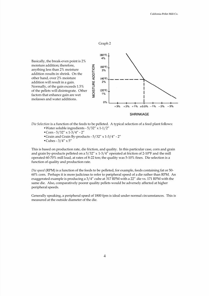
Graph 2
Basically, the break-even point is 2%moisture addition; therefore,anything less than 2% moistureaddition results in shrink. On theother hand, over 2% moistureaddition will result in a gain.Normally, of the gain exceeds 1.5%of the pellets will disintegrate. Otherfactors that enhance gain are wetmolasses and water additions.
Die Selection is a function of the feeds to be pelleted. A typical selection of a feed plant follows:•Water soluble ingredients - 5/32” x 1-1/2”•Corn - 5/32” x 1-3/4” - 2”•Grain and Grain By-products - 5/32” x 1-3/4” - 2”•Cubes - 3/4” x 5”
This is based on production rate, die friction, and quality. In this particular case, corn and grainand grain by-products pelleted on a 5/32” x 1-3/4” operated at friction of 2-10°F and the milloperated 60-70% mill load, at rates of 8-22 ton; the quality was 5-10% fines. Die selection is afunction of quality and production rate.
Die speed (RPM) is a function of the feeds to be pelleted, for example, feeds containing fat or 50-60% corn. Perhaps it is more judicious to refer to peripheral speed of a die rather than RPM. Anexaggerated example is producing a 3/4” cube at 317 RPM with a 22” die vs. 171 RPM with thesame die. Also, comparatively poorer quality pellets would be adversely affected at higherperipheral speeds.
Generally speaking, a peripheral speed of 1800 fpm is ideal under normal circumstances. This ismeasured at the outside diameter of the die.
8/3/2019 Feed Mill Info
http://slidepdf.com/reader/full/feed-mill-info 5/33
California Pellet Mill Co.
5
EQUIPMENT USED IN THE PELLETING PROCESS
The Pelleting System
The pelleting system is composed of several different machines designed to most efficiently
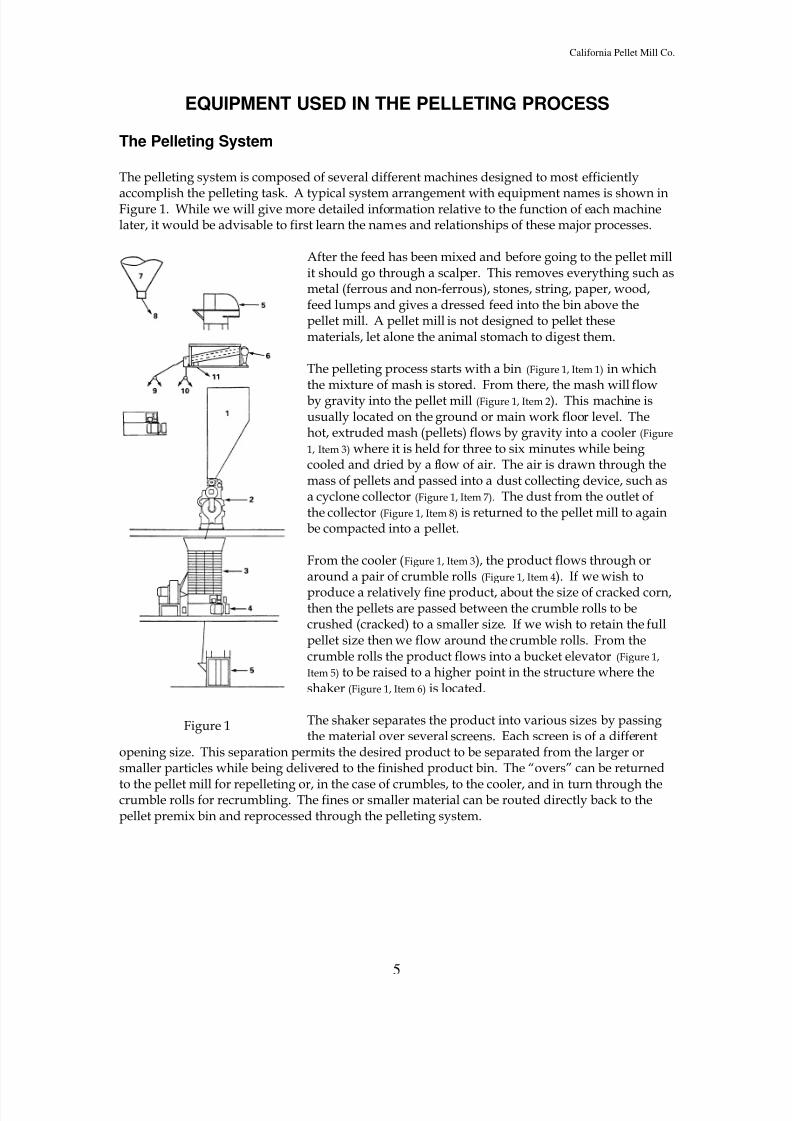
accomplish the pelleting task. A typical system arrangement with equipment names is shown inFigure 1. While we will give more detailed information relative to the function of each machinelater, it would be advisable to first learn the names and relationships of these major processes.
After the feed has been mixed and before going to the pellet millit should go through a scalper. This removes everything such asmetal (ferrous and non-ferrous), stones, string, paper, wood,feed lumps and gives a dressed feed into the bin above thepellet mill. A pellet mill is not designed to pellet thesematerials, let alone the animal stomach to digest them.
The pelleting process starts with a bin (Figure 1, Item 1) in whichthe mixture of mash is stored. From there, the mash will flowby gravity into the pellet mill (Figure 1, Item 2). This machine isusually located on the ground or main work floor level. Thehot, extruded mash (pellets) flows by gravity into a cooler (Figure
1, Item 3) where it is held for three to six minutes while beingcooled and dried by a flow of air. The air is drawn through themass of pellets and passed into a dust collecting device, such asa cyclone collector (Figure 1, Item 7). The dust from the outlet ofthe collector (Figure 1, Item 8) is returned to the pellet mill to againbe compacted into a pellet.
From the cooler (Figure 1, Item 3), the product flows through oraround a pair of crumble rolls (Figure 1, Item 4). If we wish to
produce a relatively fine product, about the size of cracked corn,then the pellets are passed between the crumble rolls to becrushed (cracked) to a smaller size. If we wish to retain the fullpellet size then we flow around the crumble rolls. From thecrumble rolls the product flows into a bucket elevator (Figure 1,
Item 5) to be raised to a higher point in the structure where theshaker (Figure 1, Item 6) is located.
The shaker separates the product into various sizes by passingthe material over several screens. Each screen is of a different
opening size. This separation permits the desired product to be separated from the larger orsmaller particles while being delivered to the finished product bin. The “overs” can be returned
to the pellet mill for repelleting or, in the case of crumbles, to the cooler, and in turn through thecrumble rolls for recrumbling. The fines or smaller material can be routed directly back to thepellet premix bin and reprocessed through the pelleting system.
Figure 1
8/3/2019 Feed Mill Info
http://slidepdf.com/reader/full/feed-mill-info 6/33
California Pellet Mill Co.
6
Supply Bins
The supply bin or bins must be adequate to store a sufficient quantity of feed immediately aheadof the pellet mill to provide not only continuous operation of the pelleting unit but alsocontinuous operation of the mixer which provides mash to the pelleting unit. Other factors in thefeed mill design may dictate a need for greater available tonnage ahead of the pellet mill thanwill be discussed here.
Generally speaking, the bin supply immediately ahead of the pellet mill should consist of at leasttwo bins, each of a capacity not less than three times the capacity of the batch mixer used tosupply feed to the pelleting unit. A bin installation of this type will usually result in an efficientoperation, both from a mixing and pelleting standpoint, and is the minimum. The maximum willbe determined by factors other than the pelleting installation.
These supply bins should be constructed so that there will be no bridging or surging. Variationsin the feed cause objectionable variations in the operation of the pellet mill. Generally, these binscan best be constructed of sheet metal. Rectangular or square construction lends itself to the bestinstallation, however, round bins may also be used.
While several pages might be devoted to the subject of hopper design, it is sufficient to say thatthe slope of the hopper sides should never be less than 60°. As many vertical sides as possibleshould be incorporated into the design. Many feed mill engineers have used the excellent,though more costly, design of having a small feed supply bin fed by start-and-stop conveyorsfrom the main supply bins. The small supply bin may have a capacity of less than 1,000 lb. andshould be equipped with bin level controls.
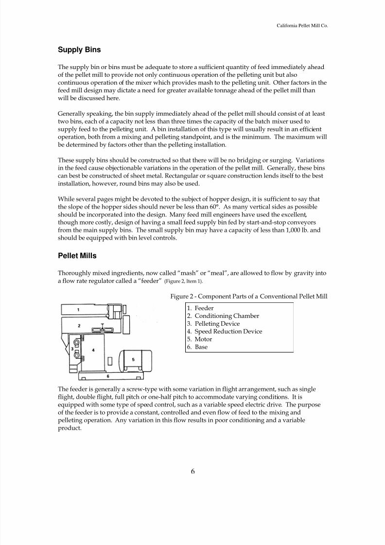
Pellet Mills
Thoroughly mixed ingredients, now called “mash” or “meal”, are allowed to flow by gravity intoa flow rate regulator called a “feeder” (Figure 2, Item 1).
Figure 2 - Component Parts of a Conventional Pellet Mill
The feeder is generally a screw-type with some variation in flight arrangement, such as singleflight, double flight, full pitch or one-half pitch to accommodate varying conditions. It isequipped with some type of speed control, such as a variable speed electric drive. The purposeof the feeder is to provide a constant, controlled and even flow of feed to the mixing andpelleting operation. Any variation in this flow results in poor conditioning and a variableproduct.
1. Feeder2. Conditioning Chamber3. Pelleting Device4. Speed Reduction Device5. Motor6. Base
8/3/2019 Feed Mill Info
http://slidepdf.com/reader/full/feed-mill-info 7/33
California Pellet Mill Co.
7
This feeder delivers a constant and prescribed amount of the “meal” to a “conditioning” chamber(Figure 2, Item 2). Here the mash is thoroughly mixed with steam (heat and water) and otherdesirable liquids, such as molasses.
A mixer is provided in order to properly condition the feed. Conditioning is almost universallyaccomplished by the addition of controlled amounts of steam. Addition of steam supplies
moisture for lubrication, liberates natural oils and, in some cases, results in partial gelatinzationof starches. Uniform conditions at this point are extremely important for optimum results.Further, this mixer can be used for the addition of up to 6-8% molasses without specialattachments when properly equipped. Mixers are supplied in low speed (up to 125 RPM) andhigh speed (125-500 RPM) models.
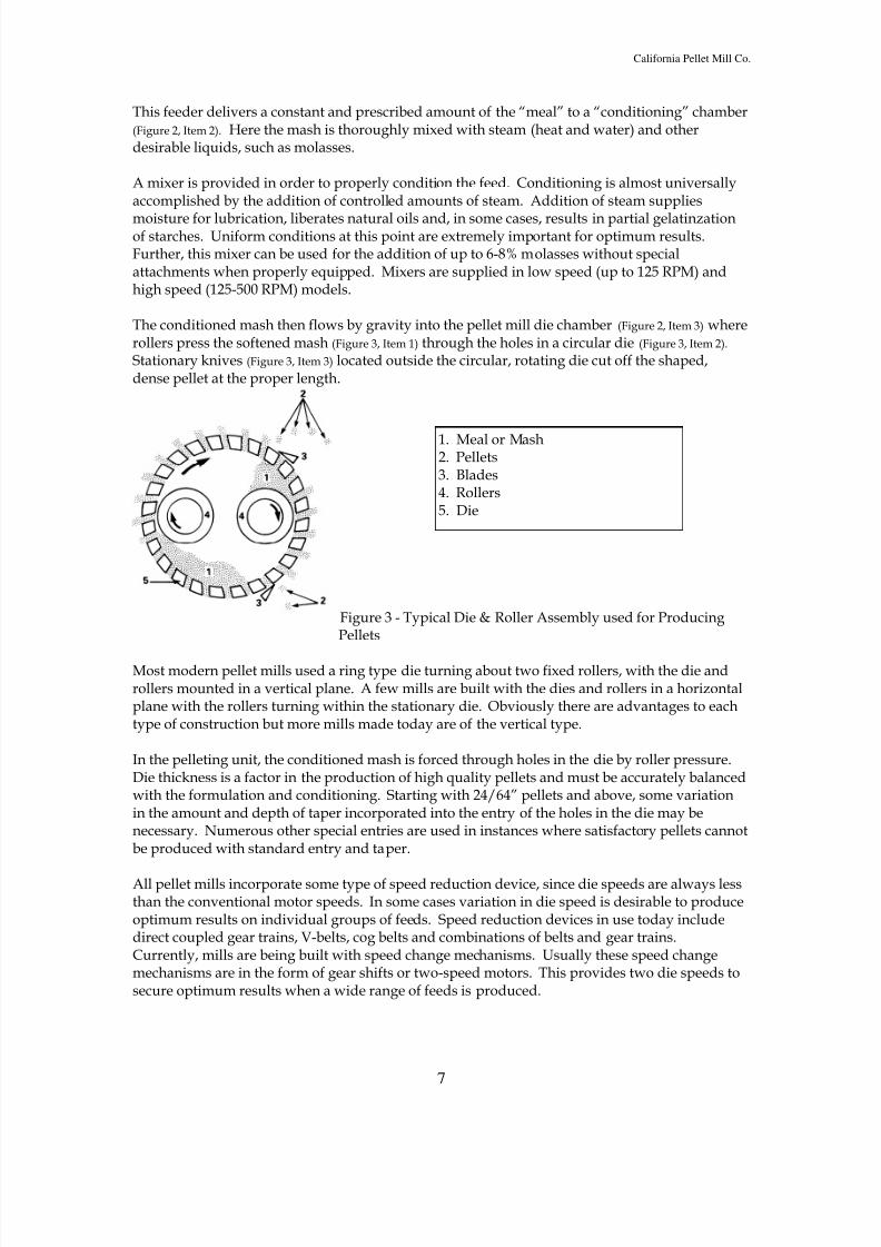
The conditioned mash then flows by gravity into the pellet mill die chamber (Figure 2, Item 3) whererollers press the softened mash (Figure 3, Item 1) through the holes in a circular die (Figure 3, Item 2). Stationary knives (Figure 3, Item 3) located outside the circular, rotating die cut off the shaped,dense pellet at the proper length.
Figure 3 - Typical Die & Roller Assembly used for ProducingPellets
Most modern pellet mills used a ring type die turning about two fixed rollers, with the die androllers mounted in a vertical plane. A few mills are built with the dies and rollers in a horizontalplane with the rollers turning within the stationary die. Obviously there are advantages to eachtype of construction but more mills made today are of the vertical type.
In the pelleting unit, the conditioned mash is forced through holes in the die by roller pressure.Die thickness is a factor in the production of high quality pellets and must be accurately balancedwith the formulation and conditioning. Starting with 24/64” pellets and above, some variationin the amount and depth of taper incorporated into the entry of the holes in the die may benecessary. Numerous other special entries are used in instances where satisfactory pellets cannotbe produced with standard entry and taper.
All pellet mills incorporate some type of speed reduction device, since die speeds are always lessthan the conventional motor speeds. In some cases variation in die speed is desirable to produceoptimum results on individual groups of feeds. Speed reduction devices in use today includedirect coupled gear trains, V-belts, cog belts and combinations of belts and gear trains.Currently, mills are being built with speed change mechanisms. Usually these speed changemechanisms are in the form of gear shifts or two-speed motors. This provides two die speeds tosecure optimum results when a wide range of feeds is produced.
1. Meal or Mash2. Pellets3. Blades4. Rollers5. Die
8/3/2019 Feed Mill Info
http://slidepdf.com/reader/full/feed-mill-info 8/33
California Pellet Mill Co.
8
Most pellet mills are installed with an electric motor as the prime mover; however, internalcombustion engines are sometimes used. When internal combustion engines are used thehorsepower rating should be at least twice that of the electric motor normally used. The pelletmill and motor are usually mounted on a common base to maintain alignment of the pellet milland motor and to provide a rapid, simple and efficient method of installing the equipment.
Although it is not a part of the pellet mill, an ammeter should be included as part of the electricalsystem. This will allow the operator to adjust the feed rate to secure the maximum capacity ofthe mill without overloading the motor.
Pelleting Dies
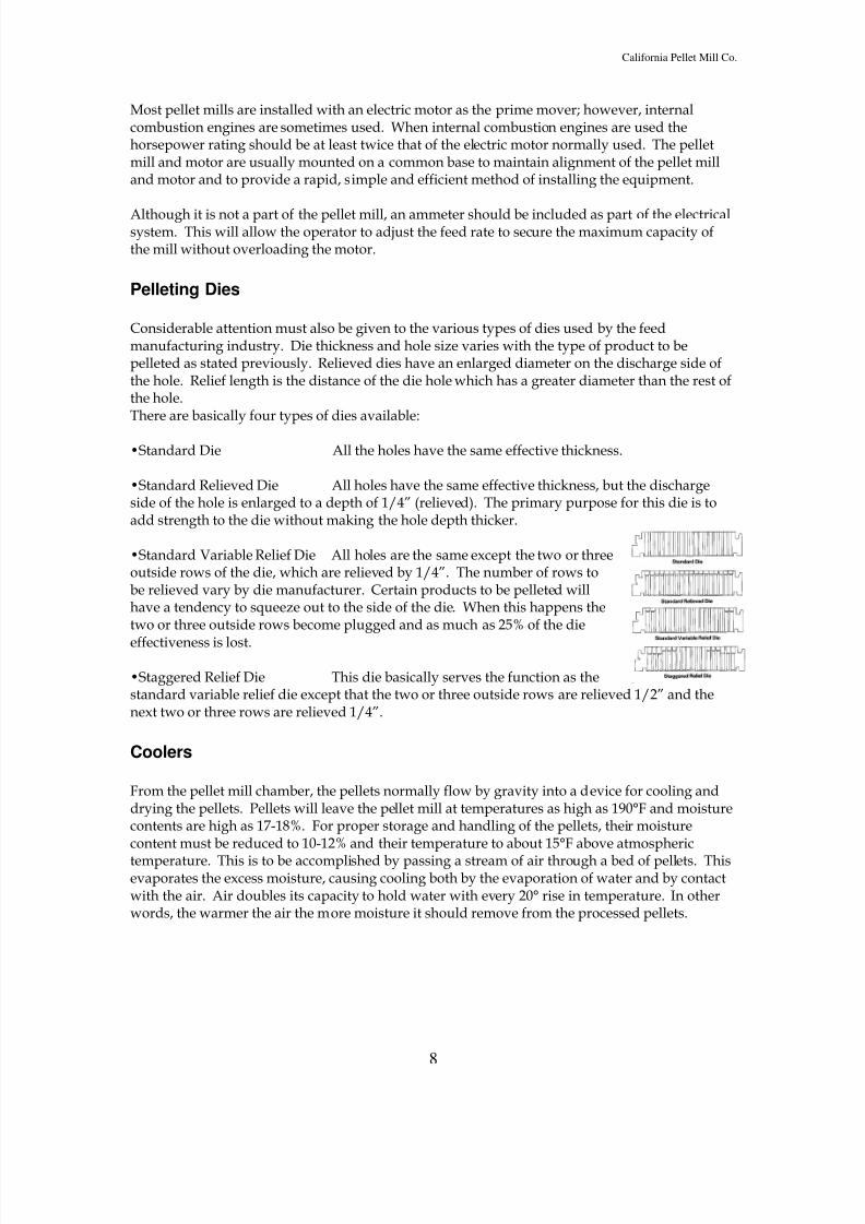
Considerable attention must also be given to the various types of dies used by the feedmanufacturing industry. Die thickness and hole size varies with the type of product to bepelleted as stated previously. Relieved dies have an enlarged diameter on the discharge side ofthe hole. Relief length is the distance of the die hole which has a greater diameter than the rest ofthe hole.There are basically four types of dies available:
•Standard Die All the holes have the same effective thickness.
•Standard Relieved Die All holes have the same effective thickness, but the dischargeside of the hole is enlarged to a depth of 1/4” (relieved). The primary purpose for this die is toadd strength to the die without making the hole depth thicker.
•Standard Variable Relief Die All holes are the same except the two or threeoutside rows of the die, which are relieved by 1/4”. The number of rows tobe relieved vary by die manufacturer. Certain products to be pelleted willhave a tendency to squeeze out to the side of the die. When this happens thetwo or three outside rows become plugged and as much as 25% of the die
effectiveness is lost.
•Staggered Relief Die This die basically serves the function as thestandard variable relief die except that the two or three outside rows are relieved 1/2” and thenext two or three rows are relieved 1/4”.
Coolers
From the pellet mill chamber, the pellets normally flow by gravity into a device for cooling anddrying the pellets. Pellets will leave the pellet mill at temperatures as high as 190°F and moisturecontents are high as 17-18%. For proper storage and handling of the pellets, their moisturecontent must be reduced to 10-12% and their temperature to about 15°F above atmospheric
temperature. This is to be accomplished by passing a stream of air through a bed of pellets. Thisevaporates the excess moisture, causing cooling both by the evaporation of water and by contactwith the air. Air doubles its capacity to hold water with every 20° rise in temperature. In otherwords, the warmer the air the more moisture it should remove from the processed pellets.
8/3/2019 Feed Mill Info
http://slidepdf.com/reader/full/feed-mill-info 9/33
California Pellet Mill Co.
9
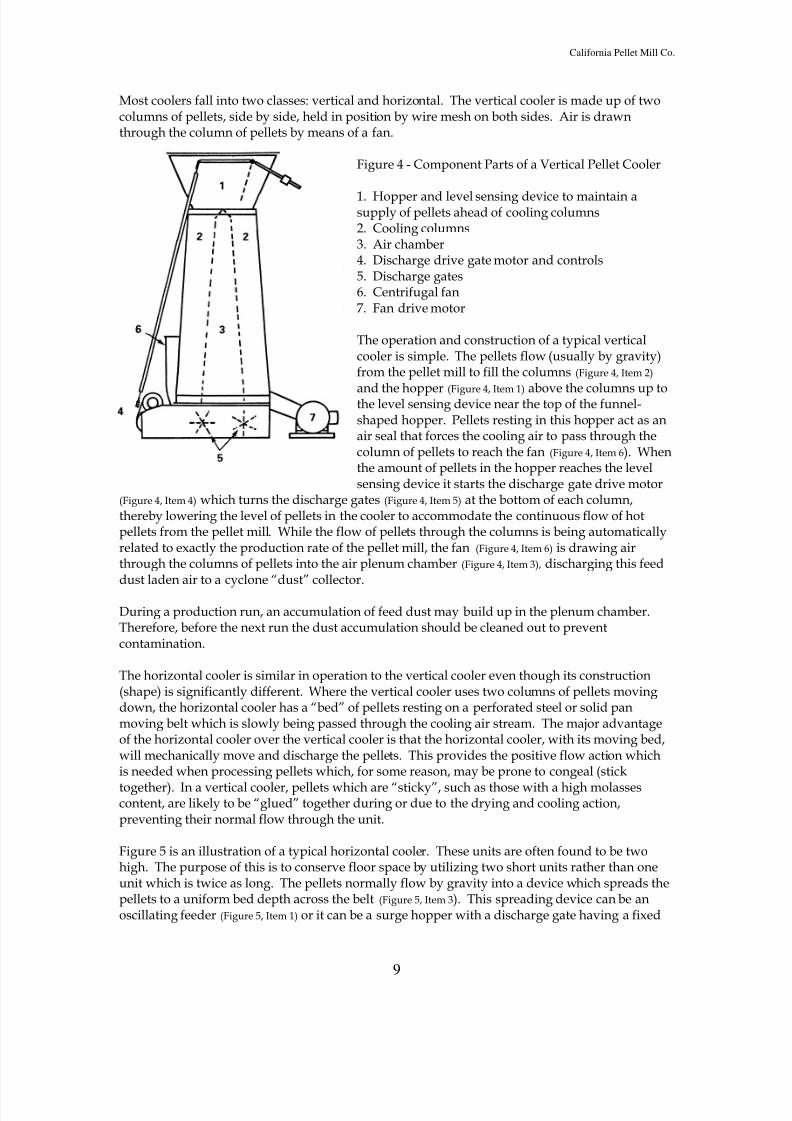
Most coolers fall into two classes: vertical and horizontal. The vertical cooler is made up of twocolumns of pellets, side by side, held in position by wire mesh on both sides. Air is drawnthrough the column of pellets by means of a fan.
Figure 4 - Component Parts of a Vertical Pellet Cooler
1. Hopper and level sensing device to maintain asupply of pellets ahead of cooling columns2. Cooling columns3. Air chamber4. Discharge drive gate motor and controls5. Discharge gates6. Centrifugal fan7. Fan drive motor
The operation and construction of a typical verticalcooler is simple. The pellets flow (usually by gravity)from the pellet mill to fill the columns (Figure 4, Item 2)
and the hopper (Figure 4, Item 1) above the columns up tothe level sensing device near the top of the funnel-shaped hopper. Pellets resting in this hopper act as anair seal that forces the cooling air to pass through thecolumn of pellets to reach the fan (Figure 4, Item 6). Whenthe amount of pellets in the hopper reaches the levelsensing device it starts the discharge gate drive motor
(Figure 4, Item 4) which turns the discharge gates (Figure 4, Item 5) at the bottom of each column,thereby lowering the level of pellets in the cooler to accommodate the continuous flow of hotpellets from the pellet mill. While the flow of pellets through the columns is being automaticallyrelated to exactly the production rate of the pellet mill, the fan (Figure 4, Item 6) is drawing airthrough the columns of pellets into the air plenum chamber (Figure 4, Item 3), discharging this feeddust laden air to a cyclone “dust” collector.
During a production run, an accumulation of feed dust may build up in the plenum chamber.Therefore, before the next run the dust accumulation should be cleaned out to preventcontamination.
The horizontal cooler is similar in operation to the vertical cooler even though its construction(shape) is significantly different. Where the vertical cooler uses two columns of pellets movingdown, the horizontal cooler has a “bed” of pellets resting on a perforated steel or solid panmoving belt which is slowly being passed through the cooling air stream. The major advantageof the horizontal cooler over the vertical cooler is that the horizontal cooler, with its moving bed,will mechanically move and discharge the pellets. This provides the positive flow action whichis needed when processing pellets which, for some reason, may be prone to congeal (stick
together). In a vertical cooler, pellets which are “sticky”, such as those with a high molassescontent, are likely to be “glued” together during or due to the drying and cooling action,preventing their normal flow through the unit.
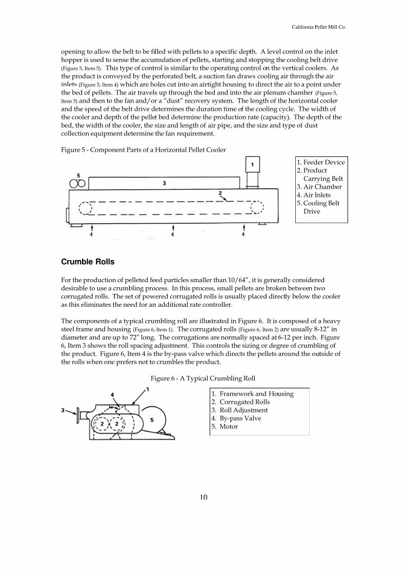
Figure 5 is an illustration of a typical horizontal cooler. These units are often found to be twohigh. The purpose of this is to conserve floor space by utilizing two short units rather than oneunit which is twice as long. The pellets normally flow by gravity into a device which spreads thepellets to a uniform bed depth across the belt (Figure 5, Item 3). This spreading device can be anoscillating feeder (Figure 5, Item 1) or it can be a surge hopper with a discharge gate having a fixed
8/3/2019 Feed Mill Info
http://slidepdf.com/reader/full/feed-mill-info 10/33
California Pellet Mill Co.
10
opening to allow the belt to be filled with pellets to a specific depth. A level control on the inlethopper is used to sense the accumulation of pellets, starting and stopping the cooling belt drive(Figure 5, Item 5). This type of control is similar to the operating control on the vertical coolers. Asthe product is conveyed by the perforated belt, a suction fan draws cooling air through the airinlets (Figure 5, Item 4) which are holes cut into an airtight housing to direct the air to a point underthe bed of pellets. The air travels up through the bed and into the air plenum chamber (Figure 5,
Item 3) and then to the fan and/or a “dust” recovery system. The length of the horizontal coolerand the speed of the belt drive determines the duration time of the cooling cycle. The width ofthe cooler and depth of the pellet bed determine the production rate (capacity). The depth of thebed, the width of the cooler, the size and length of air pipe, and the size and type of dustcollection equipment determine the fan requirement.
Figure 5 - Component Parts of a Horizontal Pellet Cooler
Crumble Rolls
For the production of pelleted feed particles smaller than 10/64”, it is generally considereddesirable to use a crumbling process. In this process, small pellets are broken between twocorrugated rolls. The set of powered corrugated rolls is usually placed directly below the cooler
as this eliminates the need for an additional rate controller.
The components of a typical crumbling roll are illustrated in Figure 6. It is composed of a heavysteel frame and housing (Figure 6, Item 1). The corrugated rolls (Figure 6, Item 2) are usually 8-12” indiameter and are up to 72” long. The corrugations are normally spaced at 6-12 per inch. Figure6, Item 3 shows the roll spacing adjustment. This controls the sizing or degree of crumbling ofthe product. Figure 6, Item 4 is the by-pass valve which directs the pellets around the outside ofthe rolls when one prefers not to crumbles the product.
Figure 6 - A Typical Crumbling Roll
1. Feeder Device2. Product
Carrying Belt3. Air Chamber4. Air Inlets
5. Cooling BeltDrive
1. Framework and Housing
2. Corrugated Rolls3. Roll Adjustment4. By-pass Valve5. Motor

8/3/2019 Feed Mill Info
http://slidepdf.com/reader/full/feed-mill-info 11/33
California Pellet Mill Co.
11
Shaker
From the crumbling device, the product (either whole or crumblized) is delivered to a screeningdevice (shaker). This is used to extract the undesirable undersized portions of the product fromthe correctly sized material. The undersized product is returned to the pellet mill for repelletingand is referred to as “recycle” or “fines”.
When a crumblized product is being made, it is likely that some pellets would not be properlybroken to a specific size. These oversized particles are also removed by screening and returnedto the original crumbler roll for reprocessing and again they are screened. Approximately 25-30% of fine materials will be returned through the crumbling process for reworking.
The majority of the screening devices used today are oscillating, vibrating, or gyrating wire ormetal screens having the appropriate opening sizes. An example of an oscillating pellet screen(or scalper) is illustrated in Figure 7. These units are composed of a steel or wood frame (Figure 7, Item 1) from which the screen (Figure 7, Items 4 and 5) are supported or suspended. The screen framesare being oscillated by an eccentrically-weighted drive unit (Figure 7, Item 2) powered by an electricmotor (Figure 7, Item 3).
Figure 7 - Component Parts of an Oscillating Pellet Scalper
Pellet Elevating Systems
The correct sized product from the shaker is now in its finished form and ready for packaging orshipment. In many mills the pellet shaker is placed on the upper floors of the structure to permitthe screened product, the oversize crumbles and the fines to flow by gravity to their correctdestination. This requires that the unscreened pellets be conveyed vertically (elevated) from thecooler to the shaker. In other cases the shaker is placed below the cooler and the sized finishedproduct is conveyed to the packaging or bulk shipping point. In either case, an elevating system(vertical conveyor) is usually required. This can be done mechanically by means of a bucketelevator (also called a “leg) or it can be done pneumatically by an air conveying system. Airsystems are sometimes used to convey hot pellets because they are not as subject to the buildupof hot, wet material as is a bucket elevator. Usually bucket elevators are used because they areless expensive to install, maintain and operate.
FEED INGREDIENT CHARACTERISTICS
1. Frame2. Drive3. Motor4. Top screen for finished pelletsand for rejection of larger-than-desired crumble particles5. Bottom screen for finishedcrumbles
8/3/2019 Feed Mill Info
http://slidepdf.com/reader/full/feed-mill-info 12/33
California Pellet Mill Co.
12
Various ingredients have characteristics that require different forms and levels of treatmentduring pelleting. Familiarity with these characteristics allows the operator to know in advancewhat effect moisture, pressure and heat will have upon individual feed formulas and anticipatewhat he can do to pellet the feed in the most efficient way.
Feed and ingredient characteristics are determined by the following factors:1. Protein 5. Texture2. Density 6. Starch or carbohydrates3. Fat 7. Moisture4. Fiber
Each feed or ingredient has a unique characteristic depending upon the variance of one or moreof these factors. Each factor has a certain latitude of variance before the characteristic of a feed oringredient is changed. For example, change the protein of 48% soybean meal by 0.2 of one percent and it is still considered 48% soybean meal. But, if the protein was analyzed as 46%, or 2%less, the ingredient would not be considered 48% soybean meal.
While ingredient suppliers are, at times, striving to keep these ingredient factors constant so thattheir quality will not vary, they have also, through modern technology, been able to reduce theamount of starches, fats and oils from these products. While these improvements normallyenhance the supplier’s primary products, we in the feed industry find it increasingly difficult topellet these ever-changing products.
The quality of pelleted feed will vary as the factors of ingredients vary. In order to keep pelletquality constant, ingredient characteristics or quality must be consistent, or compensatingadjustments made.
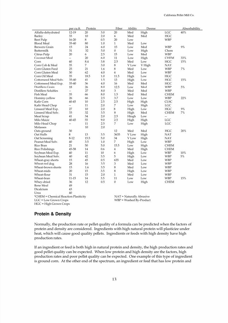
Figure 8, called the Pelletabilty Chart, lists common ingredients used in feed. The chart can beused to help predict the rate that each ingredient will pellet. The column headed “abrasiveness”
will give an indication on how this ingredient will affect die life. Each feed formula can beanalyzed using this chart to give an indication of its pelletability.
Many times pelleting rates and pellet quality are reduced, because it is not always possible tocontrol the ingredients that make up a formula or make compensating adjustments. While someleast cost formulation programs do set standards for pellet quality specifications, ingredient costscontinue to be an overriding factor when formulating the final product.
Figure 8 - Pelletability ChartProduct Weight % % Fat % Pellet Abrasiveness Reason* Molassses
8/3/2019 Feed Mill Info
http://slidepdf.com/reader/full/feed-mill-info 13/33
California Pellet Mill Co.
13
per cu.ft. Protein Fiber Ability Desree Absorbability
Alfalfa-dehydrated 12-19 20 3.0 20 Med High LGC 40%Barley 33 10 2.0 6 Med Med HGCBeet Pulp 16-20 8 0.5 20 Low WBPBlood Meal 35-40 80 1.0 1 Med LowBrewers Grain 15 24 6.0 15 Low Med WBP 9%Buttermilk 31 32 5.0 0 Low High ChemCitrus Pulp 20 6 2.5 15 Low Med WBPCoconut Meal -- 20 6.0 11 Low High CHEM 33%Corn 40 8.4 3.8 2.5 Med Low HGC 15%Corn Cob & Meal 35 7 3.0 8 V Low V High NAYCorn Gluten Feed 25 21 1.6 8 Med Low WBP 7%Corn Gluten Meal 30 62 4.0 4 Med Low WBPCorn Oil Meal 35 18.5 1.0 11.5 High Low HGCCottonseed Meal Solv. 35-40 41 1.5 13 High Low HGC 15%Cottonseed Meal Exp. 35-40 36 4.0 16 Med Med HGCDistillers Grain 18 26 8.0 12.5 Low Med WBP 5%Distillers Solubles -- 27 8.0 3 Med Med WBPFish Meal 35 66 8.0 1.5 Med Med CHEMHominy-yellow 26 66 2.5 3.7 Low Low WBP 22%Kafir Corn 40-45 10 2.5 2.5 High High CLSCKafir Head Chop -- 11 2.0 7 Low High LGCLinseed Meal Exp. 27 10 2.0 8 High Low HGC 9%
Linseed Meal Solv. 33 32 3.5 8 High Med CHEM 7%Meat Scrap 41 34 2.0 2.5 Hiogh Low --Milo Maize 40-45 55 9.0 2.5 High High LGCMilo Head Chop -- 11 2.5 7 Low High LGCMolasses 10 2.0Oats-ground 30 12 Med Med HGC 20%Oat Hulls 8 13 3.5 3635 V Low High NATOat Screening 8-12 15.5 5.0 34 V Low High NAYPeanut Meal Solv. 40 3.5 1.0 7 High Low WBPRice Bran 21 50 5.0 15.5 Low High CHEMRice Polishings 45-58 14 0.6 4 Med High CHEMSoybean Meal Exp. 40 11 10 6 High Low WBP 10%Soybean Meal Solv. 40 42 3.5 5 High Low WBP 5%Wheat-gray shorts 15 45 0.5 635 Med Low WBPWheat-red dog 28 16 3.5 3 Med Low WBPWheat-brown shorts 15 1.6 3.5 8 Med Low WBPWheat-mids 20 15 3.5 8 High Low WBPWheat-flour 31 15 2.0 1 Med Low WBPWheat-bran 11-15 14 3.5 11 Low Low WBP 15%Whey-dried 36 12 0.5 0 Low High CHEMBone Meal 49Dicalcium 43Urea 40*CHEM = Chemical Reaction Plasiticity NAT = Naturally AbrasiveLGC = Low Grown Crops WBP = Washed By-ProductHGC = High Grown Crops
Protein & Density
Normally, the production rate or pellet quality of a formula can be predicted when the factors ofprotein and density are considered. Ingredients with high natural protein will plasticize underheat, which will cause good quality pellets. Ingredients or feeds with high density have highproduction rates.
If an ingredient or feed is both high in natural protein and density, the high production rates andgood pellet quality can be expected. When low protein and high density are the factors, highproduction rates and poor pellet quality can be expected. One example of this type of ingredientis ground corn. At the other end of the spectrum, an ingredient or feed that has low protein and
8/3/2019 Feed Mill Info
http://slidepdf.com/reader/full/feed-mill-info 14/33
California Pellet Mill Co.
14
low density should produce a good quality pellet with a poor production rate. Some examples ofthis type of ingredient are alfalfa meal, ground corn cobs, cottonseed hulls and corn gluten feed.
The bulk density of a formula is an important factor in determining the rates a pellet mill willproduce. You will get less production of a light fibrous material, such as alfalfa meal which has abulk density of 17 lb. per cubic foot, as opposed to cottonseed meal which has a bulk density of
40 lb. per cubic foot off the same 100 HP pellet mill (Figure 9).
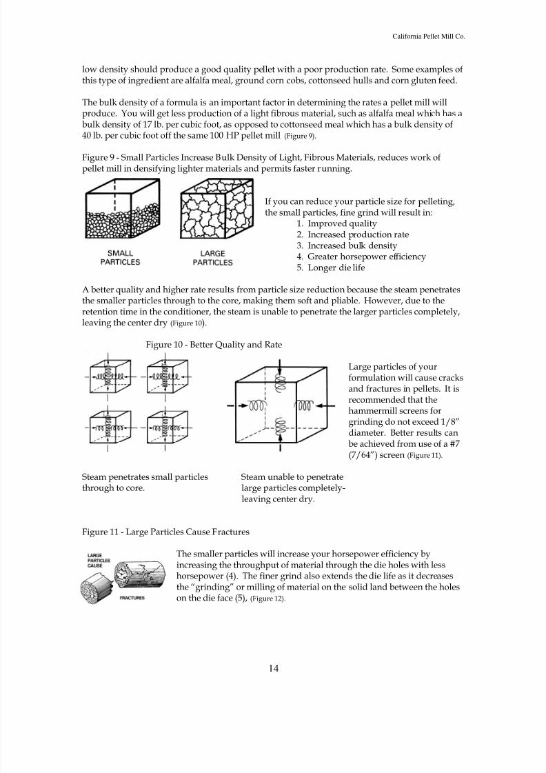
Figure 9 - Small Particles Increase Bulk Density of Light, Fibrous Materials, reduces work ofpellet mill in densifying lighter materials and permits faster running.
If you can reduce your particle size for pelleting,the small particles, fine grind will result in:
1. Improved quality2. Increased production rate3. Increased bulk density4. Greater horsepower efficiency
5. Longer die life
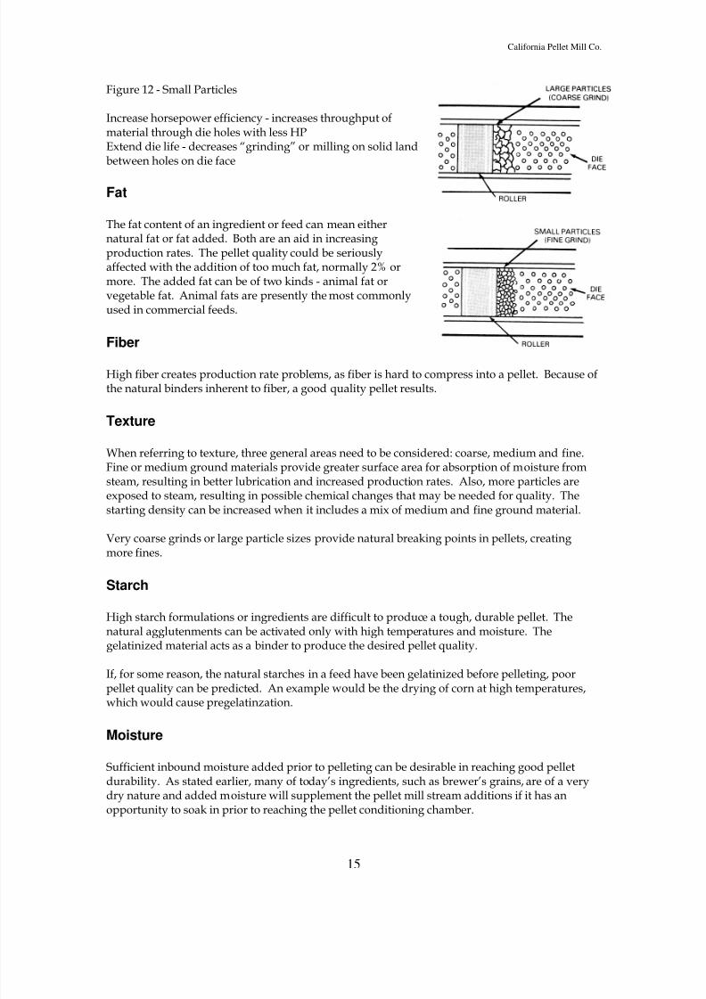
A better quality and higher rate results from particle size reduction because the steam penetratesthe smaller particles through to the core, making them soft and pliable. However, due to theretention time in the conditioner, the steam is unable to penetrate the larger particles completely,leaving the center dry (Figure 10).
Figure 10 - Better Quality and Rate
Large particles of yourformulation will cause cracksand fractures in pellets. It isrecommended that thehammermill screens forgrinding do not exceed 1/8”diameter. Better results canbe achieved from use of a #7(7/64”) screen (Figure 11).
Steam penetrates small particles Steam unable to penetratethrough to core. large particles completely-
leaving center dry.
Figure 11 - Large Particles Cause Fractures
The smaller particles will increase your horsepower efficiency byincreasing the throughput of material through the die holes with lesshorsepower (4). The finer grind also extends the die life as it decreasesthe “grinding” or milling of material on the solid land between the holeson the die face (5), (Figure 12).
8/3/2019 Feed Mill Info
http://slidepdf.com/reader/full/feed-mill-info 15/33
California Pellet Mill Co.
15
Figure 12 - Small Particles
Increase horsepower efficiency - increases throughput ofmaterial through die holes with less HPExtend die life - decreases “grinding” or milling on solid landbetween holes on die face
Fat
The fat content of an ingredient or feed can mean eithernatural fat or fat added. Both are an aid in increasingproduction rates. The pellet quality could be seriouslyaffected with the addition of too much fat, normally 2% ormore. The added fat can be of two kinds - animal fat orvegetable fat. Animal fats are presently the most commonlyused in commercial feeds.
Fiber
High fiber creates production rate problems, as fiber is hard to compress into a pellet. Because ofthe natural binders inherent to fiber, a good quality pellet results.
Texture
When referring to texture, three general areas need to be considered: coarse, medium and fine.Fine or medium ground materials provide greater surface area for absorption of moisture fromsteam, resulting in better lubrication and increased production rates. Also, more particles areexposed to steam, resulting in possible chemical changes that may be needed for quality. Thestarting density can be increased when it includes a mix of medium and fine ground material.
Very coarse grinds or large particle sizes provide natural breaking points in pellets, creatingmore fines.
Starch
High starch formulations or ingredients are difficult to produce a tough, durable pellet. Thenatural agglutenments can be activated only with high temperatures and moisture. Thegelatinized material acts as a binder to produce the desired pellet quality.
If, for some reason, the natural starches in a feed have been gelatinized before pelleting, poorpellet quality can be predicted. An example would be the drying of corn at high temperatures,
which would cause pregelatinzation.
Moisture
Sufficient inbound moisture added prior to pelleting can be desirable in reaching good pelletdurability. As stated earlier, many of today’s ingredients, such as brewer’s grains, are of a verydry nature and added moisture will supplement the pellet mill stream additions if it has anopportunity to soak in prior to reaching the pellet conditioning chamber.
8/3/2019 Feed Mill Info
http://slidepdf.com/reader/full/feed-mill-info 16/33
California Pellet Mill Co.
16
A binder may be added to the feed if adequate pellet quality is not obtained through propersteam conditioning and die selection. Two of the most widely used are bentonite and ligninsulfonate. The artificial binders add to the cost of a feed and are only used when all other meansare exhausted.
STEAM CONDITIONING
Once the ingredients are mixed and transferred to the bin, the feed flows into a feeder whichmoves the feed at the desired rate into the conditioning chamber. This is where steam andmolasses are added. Molasses is added according to the level specified by the feed formula.Steam conditioning is the most important element in achieving high quality pellets at highproduction rates at a low cost.
Reasons for Conditioning
The four basic reasons why we condition are:
1. To lubricate for faster production rate.2. To lubricate to extend die life.3. To lubricate to reduce energy costs.4. To gelatinize starch for nutritional value.
The use of steam can increase the production of a pellet mill on most all feeds. There are a fewexceptions, such as urea, mineral feeds and others that contain a lot of dried milk, whey andsugar (Figure 13).
Figure 13
Increased Production
The graph shows that when we startedthis pellet mill (30 HP) with no steamwe were running about 1200 lb./hour.By simply opening up the flow controlvalve and increasing the feed rate wefinally got the unit to a rate of 5,000lb./hour. This is now an illustration of where a pellet mill operator was running the pellet mill at160°F.
Working the pellet mill up to 200°F, the pellets became more uniform in length, a little darker in
color and had a gummy texture off the die. When we went to 205°F we plugged the pellet mill.Since the plug condition point is now known, set the pellet mill to run at 200°F and you can makea good quality product with higher production rates. The pellet mill operator should challengethe pellet mill daily to find out where the choke point is going to be, as it will vary daily.
When increasing the production rates of the pellet mill by giving it more steam, this also reducesthe fines at the pellet mill. The highest level of fines are made with no steam. This is becausematerial was dry but when steam is added materials become soft and pliable and stick together(Figure 14).
8/3/2019 Feed Mill Info
http://slidepdf.com/reader/full/feed-mill-info 17/33
California Pellet Mill Co.
17
Figure 14
Why Amount of Steam Added
Varies
As we learned in the last section, differentingredients require different treatment inthe pelleting process. Pellet milloperators must learn that the amount ofsteam that can be added will vary foreach run, because of formulation, moisture, temperature, etc.. Due to the variables, they cannotpre-determine the amount of steam to add for any run. The existing conditions must dictate howmuch steam can be added.
Formulas can be classified into six broad categories. The categories should be well understood
because each requires a different steam application. They are:
•Heat Sensitive Feeds Feeds in this group contain high percentages of dried milk,whey and sugar. These materials will start to caramelize at about 140°F. Thin dies (to reducefrictional heat) and fat added to the formula (lubrication) can aid in reducing choke-ups.Normally low pressure steam will be used.
•Urea Feeds Little or no steam should be added to this group of feeds. Urea becomes moresoluble as the temperature rises. Steam supplies the heat and moisture to dissolve the urea.When this occurs, the meal is wetter than meal without urea because the urea is acting as aliquid. The hot pellet temperature should be no higher than 150°F. Thin dies (reduce frictionalheat) should be used to keep the temperature low. Fat (lubrication) added to the formula willhelp. Too much steam causes choke-ups as well as severe bin hang-up problems. Normally highpressure steam will be used.
•Molasses Feeds The amount of steam that can be added to this group is directlyproportional to the per cent of molasses in the formula. Since molasses is approximately 26%water, the quantity of steam that can be added must be reduced or the meal will become too wet.This condition will result in choke-ups. Adding live steam into the molasses line will raise themolasses temperature to 200°F. Under these conditions, higher meal temperature can beachieved without exceeding the maximum moisture level. Normally high pressure steam isused.
•High Natural Protein Feeds This group includes supplements, concentrates and some steerand dairy feeds. Heat is more important than moisture to plasticize the protein. These feeds
require more steam than the urea and heat sensitive feeds but less than high starch formulas.Normally high pressure steam is used.
•High Grain Feeds (High Starch) Poultry, broiler, hog and turkey feeds are in this group.High temperatures and high moistures are necessary to gelatinize the starches in the grain. Thegelatinized material acts as a binder to produce tough pellets. To partially gelatinize thestarches, the meal moisture must approach 17-18% moisture and the temperature must be at least180°F. The hotter the meal, the greater the degree of gelatinization. Normally low pressuresteam is used.
8/3/2019 Feed Mill Info
http://slidepdf.com/reader/full/feed-mill-info 18/33
California Pellet Mill Co.
18
•Complete Dairy Feeds This group is usually between 12-16% in protein. Anothercharacteristic of this group is that they contain large amounts of fluffy, roughage-typeingredients and are also low in grain content. These ingredients have a low ability to acceptmoisture. Steam addition should be low to keep the meal temperature below 140°F and themaximum moisture level at 12-13%. If above levels are exceeded pellets expand and crack after
leaving the die.
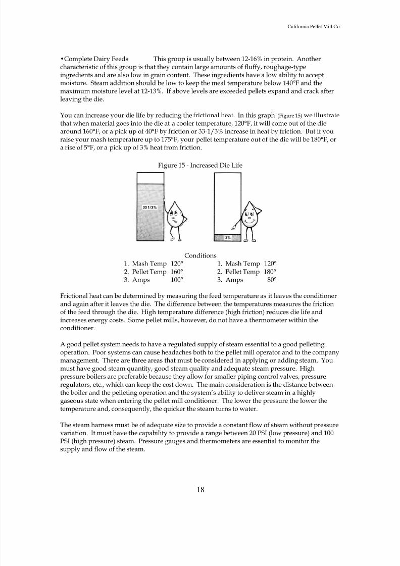
You can increase your die life by reducing the frictional heat. In this graph (Figure 15) we illustratethat when material goes into the die at a cooler temperature, 120°F, it will come out of the diearound 160°F, or a pick up of 40°F by friction or 33-1/3% increase in heat by friction. But if youraise your mash temperature up to 175°F, your pellet temperature out of the die will be 180°F, ora rise of 5°F, or a pick up of 3% heat from friction.
Figure 15 - Increased Die Life
Conditions1. Mash Temp 120° 1. Mash Temp 120°2. Pellet Temp 160° 2. Pellet Temp 180°3. Amps 100° 3. Amps 80°
Frictional heat can be determined by measuring the feed temperature as it leaves the conditionerand again after it leaves the die. The difference between the temperatures measures the frictionof the feed through the die. High temperature difference (high friction) reduces die life andincreases energy costs. Some pellet mills, however, do not have a thermometer within theconditioner.
A good pellet system needs to have a regulated supply of steam essential to a good pelletingoperation. Poor systems can cause headaches both to the pellet mill operator and to the companymanagement. There are three areas that must be considered in applying or adding steam. Youmust have good steam quantity, good steam quality and adequate steam pressure. Highpressure boilers are preferable because they allow for smaller piping control valves, pressureregulators, etc., which can keep the cost down. The main consideration is the distance betweenthe boiler and the pelleting operation and the system’s ability to deliver steam in a highlygaseous state when entering the pellet mill conditioner. The lower the pressure the lower thetemperature and, consequently, the quicker the steam turns to water.
The steam harness must be of adequate size to provide a constant flow of steam without pressurevariation. It must have the capability to provide a range between 20 PSI (low pressure) and 100PSI (high pressure) steam. Pressure gauges and thermometers are essential to monitor thesupply and flow of the steam.
8/3/2019 Feed Mill Info
http://slidepdf.com/reader/full/feed-mill-info 19/33
California Pellet Mill Co.
19
In poultry or other high grain formulas, we try to achieve the starting of a process calledgelatinization. This process starts when you reach mash temperatures of 175°F and the moisturelevel in the formula is around 17%. This is bound moisture (moisture that is contained in theingredients) and added moisture (added by steam). Most all of the moisture added by steam isremoved in the cooler.
Gelatinization is defined as “The complete rupture of the starch granule, brought about by acombination of moisture, heat and pressure and (in some instances) a mechanical shear”.
Basically, the gelatinization of starch has two results important to digestion:
1. Gelatinization enhances the ability of starches to absorb large quantities of water and thisleads to improved digestibility in almost all cases and improved feed conversion in many cases.
2. Gelatinization increases the speed at which enzymes (amylases) can break down the linkagesof starch, thus converting starch into simpler and more soluble carbohydrates.
Temperature & Moisture Relationship
Operators can be taught the fundamentals of steam application for the six broad formulacategories but, until they completely understand the meal moisture and temperature relationshipto steam addition, maximum results cannot be achieved.
Bound moisture is that moisture in the ingredients before the meal arrives at the pellet mill.Added moisture is the moisture added at the pellet mill in the form of steam and molasses. Totalmoisture of the meal is the sum of the bound and added moisture.
The choke point of a pellet mill is approximately 18% total meal moisture. Considering theformula groups that can utilize moderate to high steam addition, the quantity of steam that canbe added at the pellet mill is dependent upon the bound moisture content and the dry meal
temperature.
8/3/2019 Feed Mill Info
http://slidepdf.com/reader/full/feed-mill-info 20/33
California Pellet Mill Co.
20
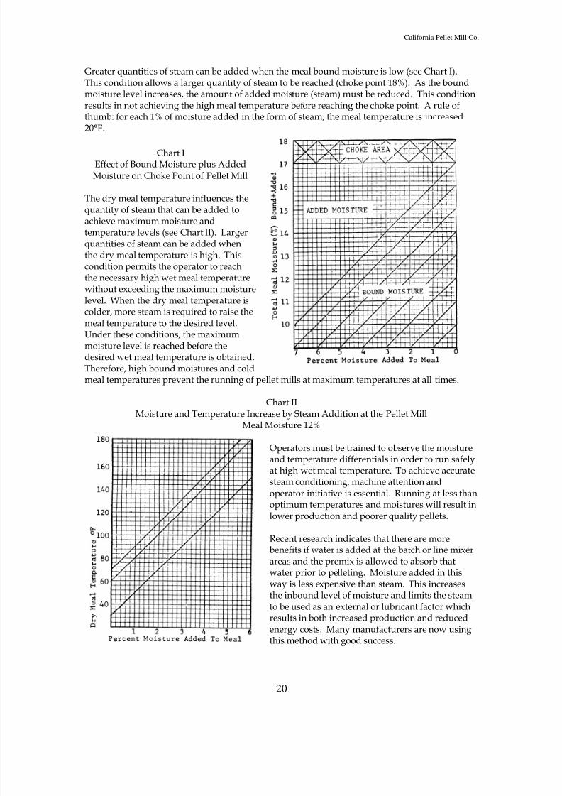
Greater quantities of steam can be added when the meal bound moisture is low (see Chart I).This condition allows a larger quantity of steam to be reached (choke point 18%). As the boundmoisture level increases, the amount of added moisture (steam) must be reduced. This conditionresults in not achieving the high meal temperature before reaching the choke point. A rule ofthumb: for each 1% of moisture added in the form of steam, the meal temperature is increased20°F.
Chart IEffect of Bound Moisture plus AddedMoisture on Choke Point of Pellet Mill
The dry meal temperature influences thequantity of steam that can be added toachieve maximum moisture andtemperature levels (see Chart II). Largerquantities of steam can be added whenthe dry meal temperature is high. Thiscondition permits the operator to reach
the necessary high wet meal temperaturewithout exceeding the maximum moisturelevel. When the dry meal temperature iscolder, more steam is required to raise themeal temperature to the desired level.Under these conditions, the maximummoisture level is reached before thedesired wet meal temperature is obtained.Therefore, high bound moistures and coldmeal temperatures prevent the running of pellet mills at maximum temperatures at all times.
Chart II
Moisture and Temperature Increase by Steam Addition at the Pellet MillMeal Moisture 12%
Operators must be trained to observe the moistureand temperature differentials in order to run safelyat high wet meal temperature. To achieve accuratesteam conditioning, machine attention andoperator initiative is essential. Running at less thanoptimum temperatures and moistures will result inlower production and poorer quality pellets.
Recent research indicates that there are morebenefits if water is added at the batch or line mixer
areas and the premix is allowed to absorb thatwater prior to pelleting. Moisture added in thisway is less expensive than steam. This increasesthe inbound level of moisture and limits the steamto be used as an external or lubricant factor whichresults in both increased production and reducedenergy costs. Many manufacturers are now usingthis method with good success.
8/3/2019 Feed Mill Info
http://slidepdf.com/reader/full/feed-mill-info 21/33
California Pellet Mill Co.
21
Conditioning of Feed Ingredients
The purpose of conditioning a mixture of feed ingredients is to uniformly penetrate each particle
with the same amount of moisture and heat, in other words, homogenization . This isaccomplished by mixing. The principles of mixing are time, temperature and turbulence.
Time Regardless of the shape or size of the particle, it requires time for moisture andheat to thoroughly penetrate the particles.
Temperature Many chemical and physical reactions increase twofold with each 10°F rise. Inthe case of wet molasses, the viscosity decreases twofold for every 10°F rise.
Turbulence A physical force produced by a paddle shaft rotating at a given speed so thatliquids and solids repeatedly contact each other.
If these principles are applied, the surface of each particle will be void of excess moisture, and/ormolasses and/or fat. This can easily be observed by inspecting the conditioning chamber. If it isclean, mixing is efficient. On the other hand, if it is coated mixing is not taking place. Theappropriate question for the above is “Why?”.
Upon adding liquids to the mixed feed ingredients, the liquid does not completely penetrate theingredient particle and, thus, the surface is coated. As these particles are mixed, they adhere toeach other, forming balls (snowball effect) and these balls coat the conditioning chamber. Thenet result is that a mixture of dry, semi-dry and wet particles enters the pellet mill die. Thiscreates erratic production and quality.
For example, an actual experience in a feedmill with two 100 HP pelleting systems with similardie size and speed, but with one variance, which was the size of the conditioner. One
conditioner was 9”x42” and the other was 12” x54”. Wet molasses was added at the conditionerto the same feed. The 9” diameter conditioner repeatedly produced molasses balls and pluggedthe mill, whereas the 12” diameter comparatively produced smaller molasses balls and producedpellets. Basically, the 12” had more holding time than the 9” conditioner.
OPERATING PROCEDURES
Start Up
The operator must know the bin and valving arrangements for the bins over the pellet mill, aswell as the bin and valving arrangements after the shaker to bulk or packer bins.
A check list may be provided for pellet mill operators to reduce costly errors and also to get thepellet mill on stream as fast as possible. A check list may contain items as listed below.
1. Name of FeedA. Die information. Hole size and thickness.B. Pellets or crumbles?
2. Bin ManagementA. Bin number from which meal will be drawn.
8/3/2019 Feed Mill Info
http://slidepdf.com/reader/full/feed-mill-info 22/33
California Pellet Mill Co.
22
B. Bin number for finished product. Is bin empty?3. Equipment Inspection
A. All motors running?B. Varispeed on pellet mill feeder turned back to minimum setting?
4. Contamination PreventionA. Run first of the run on floor to purge pellet mill feeder, conditioner and die
before running to cooler.5. Run Conditions for Maximum Capacity and Quality
A. Check thermometer to get maximum temperature.B. Check hot pellets for correct moisture addition by catching a pellet as it hasbeen made right off the die and squeezing it between the thumb and forefingerto see if it has the consistency of putty or gum (steam and/or molasses).C. Check ammeter for motor load information.D. Check hot pellets for correct knife adjustment.E. Check cooler. On vertical coolers make sure both columns are discharging.On horizontal coolers make sure belt speed is adjusted to get desired depth ofburden and that the burden depth is level.F. Check crumbler. Make adjustment on rolls for correct product sizing. Make
sure rolls are in parallel adjustment.G. Readjustment of steam and feed rate when fines begin to return. Make samecheck as in A, B, and C.H. Make capacity check.I. Record data on production sheet.
NOTE: When starting a pellet mill on subsequent runs never start the mill with the feeder settingfrom previous run. Reset feeder to the lower range of the feeder adjustment. After you haveoperated the machine on a specific product several times, you will be able to start at highersettings without fear of plugging. You will be able to bring the pellet mill to full production in avery short time by experience with the feeder setting and regulation of the steam valve.
Starting a New Die
A pellet mill with a new die installed should be started slowly. Set feeder variable speed drive atlowest setting to allow a minimum rate of feed flowing through the conditioner and to the die.
Drain condensate from steam supply line to eliminate slugs of water from entering conditioningchamber. Start motors, main drive motor, conditioner motor and feeder motor. Do not addsteam when first starting the die; allow die holes to fill with dry material. Check ammeter forload on main drive motor. If not pulling full load, increase feeder setting until it shows full load.Open steam valve slightly at this point and in a few seconds the amperage should drop back. Ifamperage drops, increase feeder setting and repeat until you have approximately 80-90% ofmaximum load. Remember, the ammeter will not drop immediately when you open the steam
valve, for it takes a few seconds for the material to reach the die to have any effect on the powerrequired to pellet.
Operate the pellet mill at this reduced load setting for two hours to allow the die holes to becomehighly polished, then adjust your mill to full load. Keep in mind that the advancement of thefeeder and steam valve setting should be slight when starting a new die.
Pelleting
8/3/2019 Feed Mill Info
http://slidepdf.com/reader/full/feed-mill-info 23/33
California Pellet Mill Co.
23
The real heart of the pelleting process is the nip point or the area where the wedge of feed isbetween the roll and the die. Most all other equipment in the pelleting process is supportiveequipment to this, the most crucial part of pelleting.
There are three points of pressure: (1) the roll acting upon the material compresses the material
into the die, (2) the die itself has a resistance that can hold back the flow of the material throughthe holes in that die, and (3) the pressure exerted by the rolls combined with the frictionalpressures of the formulation itself. This pressure keeps the material compressed together andkeeps it from squirting along the face of the die in front of the roll.
When we increase the variable speed drive or control and increase the amount of feed into thepellet mill, the amount of feed thickens in direct proportion just in front of the roll. In otherwords, there is greater force pushing the feed into the nip point instead of down into the holes ofthe die. This is normally what causes a pellet mill to plug. This slug or mat of feed can build upin front of the roll, hindering the roll’s ability to crimp and push the feed into the die holes.Thus, surges of feed should be prevented from entering into the pelleting chamber.
Feed distribution is extremely important across the face of the die and into this nip point. Feeddistribution is a problem and can cause the pad to be too deep and, again, limit the ability of theroll to force the product into the die holes. This essentially limits the production. This is why itis critical that the rolls be set on a regular basis, remembering that the feed flow through the dieis what causes the die to wear away from the rolls. The rolls should be adjusted to a point so thatthe roll will be allowed to turn.
Pelleting is a daily exercise in ability and knowledge. While large pieces of equipment arenecessary to complete the pelleting process, it should become obvious at this point that theoperator is, unquestionably, the most important factor in achieving a good pellet production andgood pellet quality. He must understand the pelleting process and be able to adjust many timesin a particular day to the ambient temperatures, humidity, formulation changes, conditions of
ingredients, and bound or inbound moisture levels of these ingredients. Running a pellet millcan be a trying, difficult process or one of great challenge for the individual. It becomes basicallyhis choice as to which he prefers.
Shut Down
Since there is as much poor product produced at the end of the run as there is at the beginning ofthe run, operators must give proper attention to all phases of the pelleting process.1. Machine Attention - be available when bins begin to empty.2. Adjustments
A. Reduce steam and molasses addition to compensate for the rerunning of fines.B. On horizontal coolers reduce belt speed.
C. Return feeder varispeed drive to minimum setting when finished running fines.D. Shut off feeder and conditioner motors.E. Purge die with oily material if die is to be changed or will be idle for 8 hours or
longer.F. Shut off mill motor.
8/3/2019 Feed Mill Info
http://slidepdf.com/reader/full/feed-mill-info 24/33
California Pellet Mill Co.
24
Maintaining Optimum Loads
Operators must learn that variables occur during the run and, therefore, machine attention isessential. In theory, there is no final adjustment on a pellet mill. To achieve maximum capacityand produce the highest quality pellets, the ammeter, thermometer and hot pellet temperaturemust be constantly monitored. Listed below are some of the items that cause variations duringthe run.
1. Bin hang up2. Bin separation3. Return of fines from shaker4. Steam pressure fluctuation
A. Boiler failureB. Pressure regulative valve failure
5. Steam quality changesA. Foaming boilerB. Steam trap failureC. Steam separator failure
6. Bound meal moisture variation
7. Heat buildup in die
Adequate control accessories must provided if the operator is expected to run at maximumcapacity and high quality. However, when control accessories are provided, a maintenanceprogram should be established to ensure no malfunctioning. Some of the control accessories thatcan be provided are:
1. Bin level alarm: Light or audible alarm is activated when bin is running empty.2. Solenoid valves: Installed on steam and molasses lines to shut off liquids if there is aninterruption of feed flow.3. Tachometers: Installed on feeder screw to indicate RPM to check capacity rates.4. Air operated pressure regulating valves: Installed to allow operator to adjust steam
pressure easily.5. Overload controls: Installed with time delays to shut off liquids, conditioner and feeder motorwhen main drive motor goes into overload condition. When overload condition no longer exists,time delays will start conditioner motor, feeder motor and liquid addition in proper sequence.6. Cooler controls: Automatic depth of burden controller to ensure maximum bed depth.7. Crumbler controls: Installed on rolls to remotely set rolls for various product sizes. Alsocontrols to operate by-pass valves remotely.8. Valve controls: Installed on spout valves for remote operation.
Housekeeping
The environment that the operator works in will have an influence on his attitude towards
production and quality. The work area and machines should be painted, clean and well-lighted.It is the duty of the operator to keep his work area and machines clean.
1. Brush down pellet mill once per day or more often if conditions warrant.2. Keep area around pellet mills clean. Sweep after each choke. Dispose of waste.3. Scraper doors and front of gearbox once per day.4. Clean feed chutes as often as necessary.5. Conditioner cleaned once per week.6. Feeder cleaned once per week.
8/3/2019 Feed Mill Info
http://slidepdf.com/reader/full/feed-mill-info 25/33
California Pellet Mill Co.
25
7. Check cleanliness of coolers once per shift.8. Operator to lubricate pellet mill per manufacturer’s recommendations.9. Check shear pins to make sure they are installed correctly.10. Clean magnets at least once per day.11. Check steam traps.12. Report any machine problems to supervisors.
13. Check knives for sharpness.14. Check roller adjustment and adjust when necessary.15. Exercise good die change practices.
Cooling
The exhaust temperature of the cooler, which is governed by the temperature of the pellets, andambient air determines the amount of moisture removal from the pellets. In turn, the cubic feetper minute of ambient air required must consider the inherent properties of air used at thespecific location. Also, as in conditioning feed, holding time becomes important. There is anequilibrium cooled pellet temperature beyond this point, excess air and holding time issuperfluous.
Cooling factors can be established based on the classification of feed (water soluble, grain andgrain by-products). These factors are as follows:
•Water Soluble Ingredients1) Relative humidity below 65%
Temperature of cooled pellet = ambient air temperature + 15°F2) Relative humidity above 65% and above 50°F
Temperature of cooled pellets = ambient air temperature + 22°F
•CubesTemperature of cooled cubes = ambient air temperature + 22°F
•Other ClassificationTemperature of pellets = ambient air temperature + 15°F
Why 15°F = ambient temperature = cooled product temperature? This is based on a watercooling tower performance. It is an ideal example, as dispersion and mixing occur veryefficiently. In this case, water can be cooled within 15°F of the ambient temperature.
Why 22°F for water soluble ingredients? In cases where the air humidity is over 65% and 50°F,the water soluble ingredients will pick up from 1% to 1.25% moisture. This would result incaking and pellet deterioration. In case of cubes, 22°F + ambient air temperature will decreasethe fines produced.
In many cases in the production of cubes, if the cooling differential exceeds 22°F the finesincrease as high as 10%.
Another physical factor should be considered - the first 10-15 minutes production from thecooler. At this time, the cooler and product are not at equilibrium with the cooling air. As aresult, the product is warmer by as much as 20-25°F. In the case of water soluble ingredients,they will cake over the holding bin valve. If physically possible, the initial cooler productionshould be recycled.
8/3/2019 Feed Mill Info
http://slidepdf.com/reader/full/feed-mill-info 26/33
California Pellet Mill Co.
26
The measuring equipment required to accomplish the above functions are a relative humiditygauge and thermometer, located in the air stream entering the cooler. Another thermometershould be located in the product being discharged from the cooler. This thermometer should beencased in a thermometer brass well so that the thermometer sensing stem doesn’t disintegratefrom abrasion.
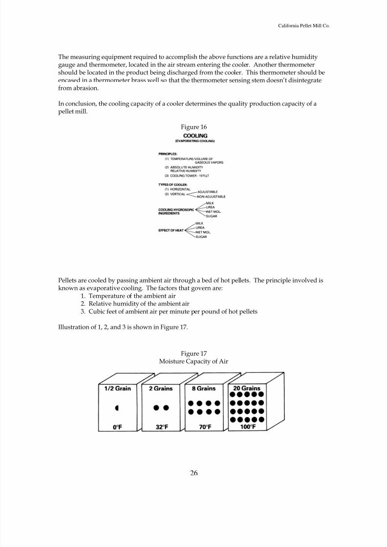
In conclusion, the cooling capacity of a cooler determines the quality production capacity of apellet mill.
Figure 16
Pellets are cooled by passing ambient air through a bed of hot pellets. The principle involved is
known as evaporative cooling. The factors that govern are:1. Temperature of the ambient air2. Relative humidity of the ambient air3. Cubic feet of ambient air per minute per pound of hot pellets
Illustration of 1, 2, and 3 is shown in Figure 17.
Figure 17Moisture Capacity of Air

8/3/2019 Feed Mill Info
http://slidepdf.com/reader/full/feed-mill-info 27/33
California Pellet Mill Co.
27
MECHANICAL ADJUSTMENTS AND MAINTENANCE
Knife Adjustment
Dull knives produce more fines at the die. Knife inspection should be made every shift.
The knife adjustment is dependent on the desired length of pellet, die speed, and thickness. Oneknife is provided for each roller. The upper knife cuts for the left hand roll and the lower knifefor the right hand roll. Two knives are used when there is sufficient extrusion at each roller toproduce the desired length pellet.
When making cubes, the knives will be adjusted away from the die as far as possible or removed.You will then use a special sickle-type cube knife or a breaker bar located above the dischargegate to regulate length.
You will be instructed as to the desired length of each pellet or cube by your supervisor.
Roller Adjustment
Accurate roller adjustment is necessary for maximum capacity and long die and roller life. Looseroll adjustment will reduce capacity and cause choke-ups. Tight roll adjustment will result inrolled over dies and excessive roll wear. Die breakage can result because of poor roll setting.
In the heat treating process, a certain amount of distortion occurs which leaves high spots on theface of the die. Both rollers should be adjusted so that when the die is turning at a low RPM, therolls should hit the high spot only. This type of adjustment prevents excessive metal-to-metalcontact between the roller and the die but exerts sufficient pressure to maintain high capacity.
Die Care
By following a few simple rules your die life will be prolonged and you will realize the greatestproduction from your dies.
Never abuse a die by striking it with a hammer or by dropping it on a hard surface. If force isnecessary to install the die, use a plastic hammer or piece of wood. The die is keyed to the quilland held in place by the die clamp. Care is necessary to have the surfaces of both the die andquill clean for proper mounting.
The die must be securely held by the die clamp at all times. A worn out die clamp or quill insertwill make proper fit and operation impossible. A loose fit at this point will cause flexing andexcessive stress on the die, rollers and drive train.
The quill insert should be replaced if it becomes worn. When mounting a new die, check the dieclamp with the gauge, which is shipped with the new die.
Magnets, scalpers and other cleaning devices are vital to the life of a die - they are to be cleanedand checked regularly to make certain they are doing the job of removing metal and other
8/3/2019 Feed Mill Info
http://slidepdf.com/reader/full/feed-mill-info 28/33
California Pellet Mill Co.
28
material from the feed. Periodic inspection of the die for presence of foreign material isadvisable. Pieces of tramp metal which have become embedded in the die should be removed bypunching or drilling from the outside end of the hole.
The care of the die is similar to that of a rifle barrel bore. The holes in the die are carefullymachined and highly polished. This hole surface must be preserved if maximum pellet capacity
is to be maintained. If the mill is going to be shut down for over one half hour or for a diechange, the die should be filled with an oily mixture.
When a die is removed from the pellet mill, store in a protected dry area. Also, when you receivea new die store it in this protected dry area to eliminate rust.
Removing the Die1. Make certain the die has been filled with an oily mixture.2. Back off cutting knives from die.3. Open pellet chamber and remove feed cone.4. Back rollers away from die.5. Remove die clamp.
6. Remove die by drawing away from mill. If is does not come loose easily, pry in theslots between the die and the quill.
7. Store in a dry place.
NOTE: For a more detailed procedure for adjusting knives and rolls and removal of die androlls, refer to manufacturer’s manual for your model pellet mill.
Maintenance of Pellet Mill Equipment
Feeders Lubrication of feeder - check oil level in variable speed drive weekly and oilroller chain sparingly. Grease front feeder bushing daily. Feeder flight bearings grease monthly.
Conditioner A clean out panel is located on the side of the conditioner chamber to permitinspection and cleaning of the mixer without removing the mixer shaft.
Lubrication Grease the bearing at each end of the mixer monthly.
Feed Chute The feed chute carries feed from the conditioning mixer to the die cavity bygravity flow. To do this job efficiently, the chute must be kept clean and free of dents. If a magnetis located in the feed chute, clean it after each run to remove metal buildup.
Deflector The purpose of the deflector is to maintain a clean surface on the cone and assureuniform distribution of feed to the die. Keep clear of caked on material which will restrict flowto the die.
Mainshaft and Drive Assembly Most models have the entire drive running in oil and needs onlythe oil changed twice yearly. On new models the front main shaft bearing needs to be greasedeach eight (8) hours of operation.
8/3/2019 Feed Mill Info
http://slidepdf.com/reader/full/feed-mill-info 29/33
California Pellet Mill Co.
29
Operator Lubrication Summary
1. Lubricate rollers at least once every four hours of continuous operation. Smalleramounts every one hour are also recommended (Grease rolls at end of runs to keep out feedmaterial. The grease in the rolls will contract when allowed to cool and will draw feed materialinto bearings.).
2. Lubricate main shaft bearing every eight hours.
3. Change gearbox oil every 2,000 hours or every six months.
4. Check oil level in feeder drive weekly and oil roller chain drive sparingly.
5. Grease conditioner and feeder shaft bearings monthly.
6. Grease knife brackets daily and work manually to keep free.
Keep machine clean. Blow off dust, wipe up excess oil or grease accumulations.
QUALITY CONTROL
The quality of a pellet will be based largely on the following factors:•Fines•Color•Size•Appearance
Fines are a major factor in determining consumer satisfaction with pelleted feed quality.Producing a tough pellet will eliminate most fines complaints. The section on conditioning hasdealt with producing a tough pellet.
A rule of thumb for the industry has been a maximum of 10-20% fines in pelleted feed. The percent of fines can be determined by the use of sieves.
Normally, color is a very important part of determining the quality of pelleted feed. If there hasbeen no formula change it is a good check on mixing and the addition of liquids, such asmolasses and fat.
The size of pellet also helps determine quality. The length of a pellet varies from two to threetimes the hole size of a die. For example, a 3/16” diameter pellet will have a length ofapproximately 1/2”. The shape of the cross-section of a pellet can vary, with the majority beingeither round or square.
The appearance of the outer surface of a pellet will give an indication of the pellet quality. Arough exterior, not a shiny glazed surface, is desired and will indicate that a tough, durable pellethas been produced.
8/3/2019 Feed Mill Info
http://slidepdf.com/reader/full/feed-mill-info 30/33
California Pellet Mill Co.
30
Quality Tests
Operators should be instructed to make quality checks at the pellet mill and at the cooler of thefinished product.
At the Pellet Mill
Thermometers should be used to check the wet meal temperature. The thermometers should beused only as a guide. The reading will give a general indication because, on some days, a givenformula can be run hotter than on other days. Hot pellet temperatures should be checked if heatsensitive feeds and urea feeds are being run.
A physical test of the hot pellets is necessary to determine the amount of moisture in the product.A hot pellet should be placed between the thumb and forefinger and mashed into the shape of awafer. It should be the consistency of putty and should not crumble. If the wafer is mealy anddry, more steam should be added until the putty consistency is achieved.
At the Cooler and/or Packer
Portable hardness testers should be used to determine the pellet hardness for each run. If aminimum hardness standard is not reached, the operator should shut down and consult with hissupervisor.
Checking cool pellet temperatures will detect any malfunctioning of the cooling system.
SAFETY
As with all modern machines, equipment for the production of pelleted feed has been housed
and guarded so as to virtually eliminate all opportunities for injury to personnel during normaloperation. Yet injuries continue to occur. The great majority of these injuries are due toabnormal conditions causing, or coupled with, some hazardous action by the operator. Manytimes these hazardous actions are an attempt on the part of the operator to correct the abnormalsituation more quickly to return to normal operations sooner. We can admire any operator forhis diligence in these cases but we must censure him for his carelessness. An example of this isthe maintenance man who was greasing the crumble rolls and noticed that a bolt too large toenter the rolls was rolling between the rolls. In an attempt to pick the bolt out, his fingers werecaught, resulting in the loss of two fingers. This accident occurred because he failed to shut offthe machine.
Cleaning equipment while it is running, or starting equipment while it is being serviced, is a verycommon cause of injury and must be guarded against. One of the better methods of preventing
this type of accident is to disconnect the power to that equipment and either padlock or hang ared danger tag on the switch.
The opportunity for this kind of accident to happen is very great in the pelleting area. We findmuch need for cleaning and servicing this high power equipment. In addition to the crumblerolls, the conditioner, the die chamber, the cooler, the elevator, and the screen all requireservicing and cleaning. All of these have sufficient power and machinery motion to cause severeinjury.
8/3/2019 Feed Mill Info
http://slidepdf.com/reader/full/feed-mill-info 31/33
California Pellet Mill Co.
31
Pellet mill operators, as well as all mill employees, are constantly exposing themselves to othercommon safety hazards. For instance, electrical shock, through the use of worn drop cords ordamaged electrical conduits, is a constant danger. One must be watchful for the signs of theseopportunities for electrical failure. Usually they are easily detected by a simple visual inspection.
Another common injury sustained by pellet mill operators is falls. The size of his equipment
sometimes requires him to climb to inspect or service some part. He must take care that theladder he uses is safe to use on the job he is doing and then he must work with care.
A pellet mill operator finds his machinery on many floors of his mill. This necessitates a greatdeal of movement from one place to another. Many times it may be desirable to move hurriedly.Care must be taken in these movements, even though he maintains a clean and non-slipperyfloor surface.
Each man is expected to carry the prime responsibility for his own safety and the safety of hisfellow employees. This responsibility not only requires that he work carefully and safely butalso that he insist:
1. The company should provide the proper, safe tools and work area.
2. The machines should be shut off and “locked out” before being serviced.3. The use of machine guards, protective equipment and other safety devices should bemandatory.
4. His fellow employees must practice good safety procedures.5. Everyone should be safety conscious, giving safety the attention it deserves.
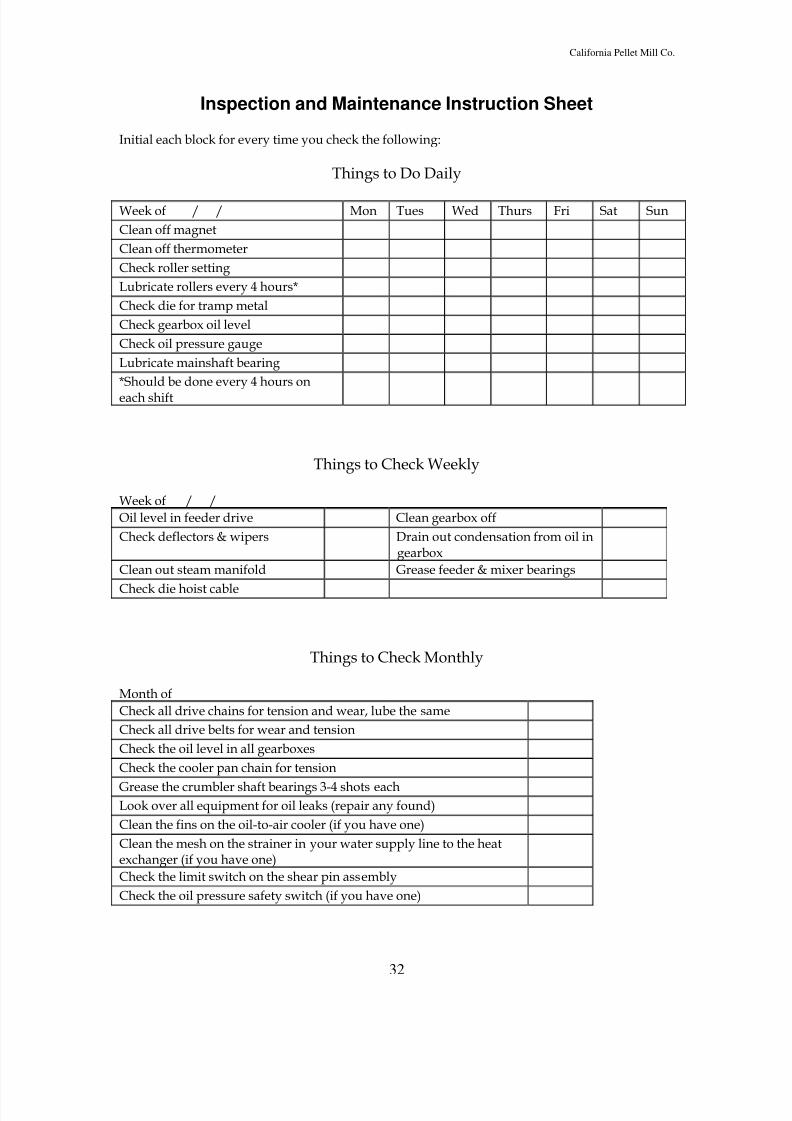
8/3/2019 Feed Mill Info
http://slidepdf.com/reader/full/feed-mill-info 32/33
California Pellet Mill Co.
32
Inspection and Maintenance Instruction Sheet
Initial each block for every time you check the following:
Things to Do Daily
Week of / / Mon Tues Wed Thurs Fri Sat Sun
Clean off magnet
Clean off thermometer
Check roller setting
Lubricate rollers every 4 hours*
Check die for tramp metal
Check gearbox oil level
Check oil pressure gauge
Lubricate mainshaft bearing
*Should be done every 4 hours on
each shift
Things to Check Weekly
Week of / /
Oil level in feeder drive Clean gearbox off
Check deflectors & wipers Drain out condensation from oil ingearbox
Clean out steam manifold Grease feeder & mixer bearings
Check die hoist cable
Things to Check Monthly
Month of
Check all drive chains for tension and wear, lube the same
Check all drive belts for wear and tension
Check the oil level in all gearboxes
Check the cooler pan chain for tension
Grease the crumbler shaft bearings 3-4 shots eachLook over all equipment for oil leaks (repair any found)
Clean the fins on the oil-to-air cooler (if you have one)
Clean the mesh on the strainer in your water supply line to the heatexchanger (if you have one)
Check the limit switch on the shear pin assembly
Check the oil pressure safety switch (if you have one)
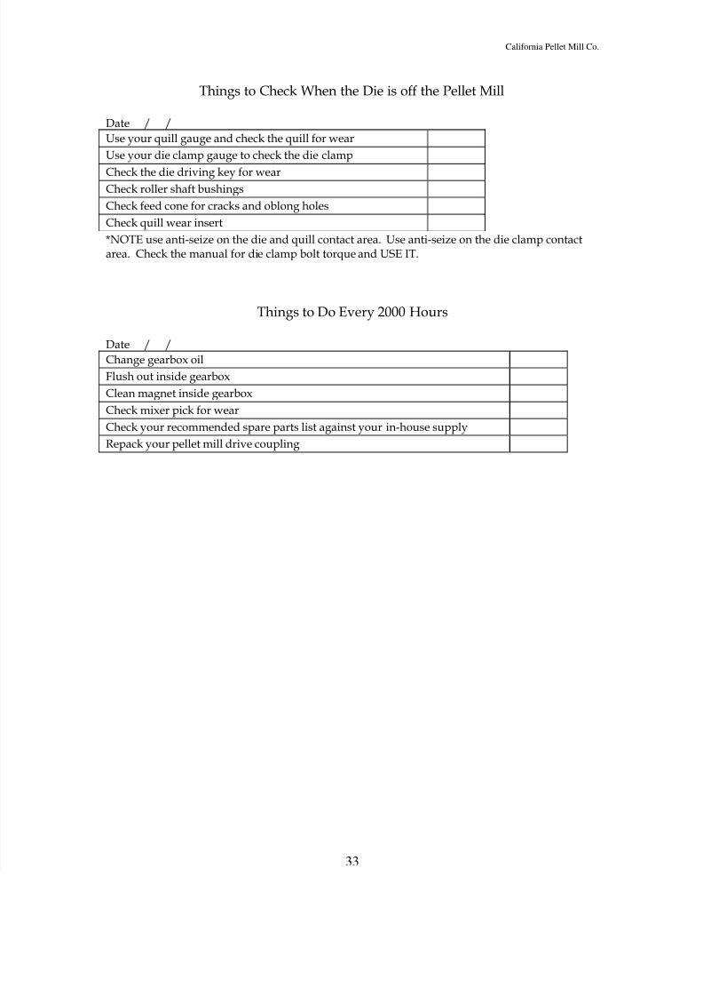
8/3/2019 Feed Mill Info
http://slidepdf.com/reader/full/feed-mill-info 33/33
California Pellet Mill Co.
Things to Check When the Die is off the Pellet Mill
Date / /
Use your quill gauge and check the quill for wear
Use your die clamp gauge to check the die clamp
Check the die driving key for wearCheck roller shaft bushings
Check feed cone for cracks and oblong holes
Check quill wear insert
*NOTE use anti-seize on the die and quill contact area. Use anti-seize on the die clamp contactarea. Check the manual for die clamp bolt torque and USE IT.
Things to Do Every 2000 Hours
Date / /Change gearbox oil
Flush out inside gearbox
Clean magnet inside gearbox
Check mixer pick for wear
Check your recommended spare parts list against your in-house supply
Repack your pellet mill drive coupling


![Animal Feed Mill[1]](https://static.fdocuments.us/doc/165x107/553da3444a7959632d8b46e3/animal-feed-mill1.jpg)
