Indonesian throughflow proxy from satellite altimeters and ...
February 4, 2020 VIA ELECTRONIC FILING Ms. Marlene H. Dortch, Secretary Federal Communications Commission Office of the Secretary 445 12th Street, SW Washington, DC 20554 Re: Notice of Ex Parte Meeting, GN Docket No. 18-122 Dear Ms. Dortch, On behalf of the Aerospace Vehicle Systems Institute (“AVSI”) project team, the attached report “Effect of Out-of-Band Interference Signals on Radio Altimeters” is provided to the Commission as a supplement to the preliminary report filed by AVSI on October 22, 2019 in support of the Commission’s ongoing work with GN Docket 18-122 to address the potential for interference to adjacent band aviation safety systems.1 This report summarizes the supplemental experimental studies undertaken by the AVSI project team to characterize the behavior of Radio Altimeters (“RAs”) operating within the 4200 – 4400 MHz frequency band while exposed to radio signals in the adjacent 3700 – 4200 MHz frequency band. In reviewing the report, the AVSI project team wishes to reiterate the report’s caveats: • While the altimeters considered in the testing are representative of the majority of systems
fielded by commercial and private aviation, it is not a comprehensive set of data for all altimeters operating under all conditions. Therefore, an additional variance in radio altimeter performance should be expected and accounted for as plans for the 3700 – 4200 MHz band are finalized. The data in this report have been released as quickly as possible to ensure the FCC has additional information to consider in its NPRM process.
• These interim results are useful for analyzing some, but not all, potential 5G scenarios being considered by the FCC in its NPRM. The AVSI project team strongly recommends that any future studies consider the worst-case flight and potential 5G deployment scenarios to ensure all possible RF interactions with RAs do not impact flight safety. The attached report has also been provided to the U.S. Federal Aviation Administration (“FAA”), and any future studies should similarly consult with the FAA to assure continued public safety in the national airspace.
• The data in this report are consistent with existing protection criteria for radio altimeters.2 Future studies should demonstrate compliance with these criteria, including the necessary safety margin required by the International Civil Aviation Organization (“ICAO”) for safety-critical systems when conducting such studies.
1 See Behavior of Radio Altimeters Subject to Out-Of-Band Interference, attachment to Letter of Dr. David Redman, Aerospace Vehicle Systems Institute, to Marlene H. Dortch, Secretary, Federal Communications Commission, Docket No. 18-122 (filed Oct 22, 2019). 2 See International Telecommunication Union, ITU-R M.2059-0, Operational and technical characteristics and protection criteria of radio altimeters utilizing the band 4200-4400 MHz (2014).
The AVSI is continuing its investigations to fully characterize the impact of out-of-band interference on RA performance, including different altimeters, altitudes, and interference signals. AVSI is also providing the results in the attached report to ICAO for review and validation by the international aviation community. This report and follow on work will support the on-going effort to develop a new international aviation standard for radio altimeter implementation in civil aviation.
Respectfully submitted, /s/ David Redman Dr. David Redman – Aerospace Vehicle Systems Institute On behalf of the AVSI AFE 76s2 project team
cc: Ron Repasi Michael Ha Ira Keltz Kenneth Baker
© 2020 Aerospace Vehicle Systems Institute
AFE 76s2 Report Effect of Out-of-Band
Interference Signals on Radio Altimeters
Supplement to Preliminary Report dated 22 October 2019
Authors: AFE 76s2 Project Members Date: 4 February 2020
Issue:1.0
Document ID: 76S2-REP-02 Release Status: Public
Approved: 4 February 2020
Aerospace Vehicle Systems Institute 754 HRBB - MS 3141 College Station, TX 77843-3141 Office: +1-979-862-2316 Web: www.avsi.aero
© 2020 Aerospace Vehicle Systems Institute i
Document Revisions
REV DATE Author(s) Modifications Approved
1.0 2/4/2020 AFE 76s2 Project Members
Document approved for public release 2/4/2020
© 2020 Aerospace Vehicle Systems Institute ii
Acknowledgements The members of the AVSI AFE 76s2 Project that contributed to this research included: Airbus Uwe Schwark, Thomas Meyerhof, Jean-Luc Robin, Laurent Azoulai, Claude
Pichavant ASRI Andrew Roy AVSI David Redman, Fred Fisher, Josh Ruff, Inderdeep Singh, Francisco Espinal Collins Aerospace Radek Zakrzewski, Sai Kalyanaraman, Jesse Oltrogge Embraer Aristides Cintra FAA Mike Biggs Garmin Eddie Straub, Clay Barber Honeywell Seth Frick IATA Noppadol Pringvanich Lufthansa Technik Steffen Mersch NASA Truong Nguyen, Gary Hunter, Sky Yarlborough Safran Steve Rines, Oliver Lücke Thales Philippe Bontemps, Stephane Tallet, Ivan Martin
© 2020 Aerospace Vehicle Systems Institute iii
Table of Contents Document Revisions ............................................................................................................................... i Acknowledgements ................................................................................................................................ ii Table of Contents .................................................................................................................................. iii List of Figures ....................................................................................................................................... iv List of Tables .......................................................................................................................................... v List of Acronyms ................................................................................................................................... vi Disclaimer ............................................................................................................................................ vii 1 Introduction ..................................................................................................................................... 1
1.1 AVSI ........................................................................................................................................ 1 2 Background ..................................................................................................................................... 2
2.1 Usage of Radio Altimeters ....................................................................................................... 2 2.2 Certification Requirements for RA Systems ............................................................................ 2
3 Progress Since Previous AVSI Results .......................................................................................... 3 4 Test Description .............................................................................................................................. 4 5 Test Results .................................................................................................................................... 5
5.1 Interference Power Threshold Definition ................................................................................. 5 5.2 Aggregated OoB Interference .................................................................................................. 5 5.3 Combined Interference Tolerance Masks for 20 and 100 MHz OoBI Bandwidths .................. 6
6 Discussion of Results ..................................................................................................................... 8 7 Conclusions .................................................................................................................................. 10
© 2020 Aerospace Vehicle Systems Institute iv
List of Figures Figure 1: Combined Interference Mask for Altimeters Type 1-6 (20 MHz OoB, 200 ft) ......................... 7 Figure 2: Combined Interference Mask for Altimeters Type 1-6 (20 MHz OoB, 2000 ft) ....................... 7 Figure 3: Combined Interference Mask for Altimeters Type 1-6 (100 MHz OoB, 200 ft) ....................... 8
© 2020 Aerospace Vehicle Systems Institute v
List of Tables Table 1: OoB Interference Threshold Powers vs. Bandwidth 6
© 2020 Aerospace Vehicle Systems Institute vi
List of Acronyms 5G fifth-generation mobile telephone AFE authority for expenditure ASRI Aviation Spectrum Resources, Inc. AVSI Aerospace Vehicle Systems Institute dB decibel dBm decibel-milliwatts FAA U.S. Federal Aviation Administration FCC U.S. Federal Communications Commission FDR frequency dependent rejection FMCW frequency modulated continuous wave FSMP Frequency Spectrum Management Panel (part of ICAO) IATA International Air Transport Association ICAO International Civil Aviation Organization IF intermediate frequency ITM interference tolerance mask ITU-R International Telecommunication Union - Radiocommunication Sector MHz megahertz NASA U.S. National Aeronautics and Space Administration NCD no computed data OFDM orthogonal frequency-division multiplexing OoB out-of-band OoBI out-of-band interference PSD power spectral density RA radio altimeter RF radio frequency TAMU Texas A&M University TAWS terrain avoidance warning system TDD time division duplex VCO voltage-controlled oscillator VSG vector signal generator WAIC wireless avionics intra-communications WCLS worst-case landing scenario
© 2020 Aerospace Vehicle Systems Institute vii
Disclaimer The intent of this study is limited to measuring the effects of out-of-band signals on radio altimeter performance. The data herein are provided to other parties to support ongoing efforts to analyze the impact of potential spectrum reallocation in the adjacent frequency band of 3700 – 4200 MHz. The data herein is provided as is and use or interpretation of this data must be consistent with the experimental conditions under which it was produced. As the specific implementation details of out-of-band signals in the 3700 – 4200 MHz band are yet to be determined, no attempt was made to implement high fidelity simulations of any specific interference environments that may occur under proposed reallocation scenarios. The empirically derived interference threshold powers herein provide a preliminary indication of the susceptibility of radio altimeters to out-of-band interference (OoBI) signals with specific characteristics. AVSI is continuing to perform additional testing to develop a more complete understanding of OoBI effects on radio altimeters.
© 2020 Aerospace Vehicle Systems Institute 1
1 Introduction This report summarizes the latest testing developments conducted by the Aerospace Vehicle Systems Institute (AVSI) to characterize the behavior of Radio Altimeters (RAs) operating within the 4200 – 4400 MHz frequency band while exposed to adjacent radio frequency (RF) emissions in the 3700 – 4200 MHz frequency band. The overarching goal of the study was to determine the sensitivity of representative commercial RAs to out-of-band interference (OoBI), as requested by the International Civil Aviation Organization (ICAO).1 While the testing group could not feasibly acquire every RA model currently in use, the units obtained were known to be common to many airframes across a spectrum of price points, deployments and capabilities and thus they are representative of the majority of RAs currently in use. Thus, the data enclosed are the best available at this time. Given the unknown details about the fifth-generation mobile telephone (5G) terrestrial networks’ RF environment in the 3700 – 4200 MHz band, the AVSI tests have used an approximation of the expected orthogonal frequency-division multiplexing (OFDM) signals the radio altimeter would receive. These OFDM interference signals have been simulated using a variety of power levels, bandwidths and center frequencies. AVSI acknowledges that network deployments across multiple potential providers, licensed bandwidths and their respective power levels will not be an exact match for the simulated interference signals used in this testing. However, the resultant data does provide the best available baseline of the radio altimeters’ performance for such an assessment, with additional commentary on possible variations as the 5G environment may change. The testing described in this report is based upon the previous test setup as detailed in the AVSI preliminary report published October 2019.2 For expediency, details of the testing process and necessary background to the testing are only briefly summarized in this report. The necessary details will be addressed by referrals to the relevant sections in the preliminary report. A detailed discussion of the new results on the behavior of RAs in response to the potential new RF environment in the 3700 ‒ 4200 MHz band is included, as well as a summary of possible uses of the results and further actions. This report also includes additional details that should help address recent public comments concerning the AVSI Preliminary Report.3
1.1 AVSI AVSI is an aerospace industry research cooperative based at Texas A&M University (TAMU) that facilitates pre-competitive research projects among its members, which include organizations from the aerospace industry, related government agencies, and academia. This project (AFE 76s2) was organized under AVSI to empirically determine in a laboratory setting the characteristics of OoBI that degrade RA performance. AVSI/TAMU provided a neutral, standard test setup that supported “black-box” testing of commercial RAs — altimeters were tested without knowledge of proprietary features of the equipment by providing stimuli through the externally accessible receive port of the altimeter and while monitoring the reported altitude on the standard avionics bus output. Project members
1 ICAO, Job Card FSMP.006.01, Develop radio frequency and interference rejection characteristics for radio altimeters
(2016). 2 See Behavior of Radio Altimeters Subject to Out-Of-Band Interference, attachment to Letter of Dr. David Redman,
Aerospace Vehicle Systems Institute, to Marlene H. Dortch, Secretary, Federal Communications Commission, Docket No. 18-122 (filed Oct 22, 2019) (“AVSI Preliminary Report”).
3 See Letter from Steve B. Sharkey, Vice President, Government Affairs Technology and Engineering Policy, T-Mobile USA, Inc. to Ms. Marlene H. Dortch, Secretary, FCC, GN Docket No. 18-122, and Attachment, Alion Review of AVSI Report, “Preliminary Report: Behavior of Radio Altimeters Subject to Out-Of-Band Interference”, Alion Science and Technology Corporation (filed Jan. 22, 2020).
© 2020 Aerospace Vehicle Systems Institute 2
contributed material resources and technical expertise. Contributors to this project included Airbus, Aviation Spectrum Resources, Inc. (ASRI), Collins Aerospace, Embraer, U.S. Federal Aviation Administration (FAA), Garmin, Honeywell, International Air Transport Association (IATA), Lufthansa Technik, U.S. National Aeronautics and Space Administration (NASA), Safran, Texas A&M University, and Thales.
2 Background 2.1 Usage of Radio Altimeters The radio altimeter is a core aviation navigational system that provides a continuous report of the aircraft’s height over terrain for varying altitude ranges below 8000 ft; however, they remain operational during all phases of flight. Altimeters are required to provide an accurate height whenever clearance above terrain is less than the maximum operational height, regardless of the aircraft’s absolute altitude above sea level. For example, clearance above terrain may be reported during the cruise phase of flight while over mountainous terrain. The system provides data to both the pilot display and automated systems on airframes, such as ground proximity warning, terrain awareness and warning (TAWS), flight control and deployment of altitude dependent systems. The radio altimeter is a critical safety function in landing/take-off, low level maneuvering, and avoiding changes in terrain that may not be visible at night or during bad weather. Nearly all civilian altimeters utilize frequency modulated continuous wave (FMCW) operation, transmitting a sweeping single frequency rapidly up and down the 4200 – 4400 MHz band. The signal is reflected off the ground or other obstacles and the radio altimeter receiver then processes all returns. Measurement of the time delay between transmission and reception of the reflected signal are used to calculate the altitude, requiring an accuracy tolerance of 3 ft or less for altitudes below 100 ft. The altimeters swept bandwidth must be a relatively large frequency range in order to provide the necessary accuracy for the application. Therefore, altimeters can operate nearly to the 4200 – 4400 MHz band edge. Altimeters were widely introduced after a number of aviation incidents up to the 1970’s of aircraft flying unintentionally into the ground – a circumstance formally known as controlled flight into terrain. The radio altimeter and the functions that use it (such as TAWS) have significantly improved aviation safety for all aircraft types since its introduction and is now an essential component of automated landings, which increases the safety and efficiency of air travel. Over 55,000 aircraft across the U.S. are now equipped with radio altimeters including large commercial aircraft, helicopters and private aircraft. Additionally, many thousands of international aircraft enter US airspace every day operating the same internationally standardized system. Medium to large aircraft are often fitted with two or three altimeters operating simultaneously to meet system reliability, continuity and integrity requirements, given their importance to safety of flight.
2.2 Certification Requirements for RA Systems As a system critical to safety of flight, stringent requirements are placed on the performance of radio altimeters. 14 CFR 25.1309 states the requirement that “The occurrence of any failure condition which would prevent the continued safe flight and landing of the airplane is extremely improbable," and FAA Advisory Circular (AC) 25.1309-1A further defines “extremely improbable” as failure conditions that
© 2020 Aerospace Vehicle Systems Institute 3
have “a probability on the order of 1 X 10⁻⁹ or less."4,5 These and equivalent requirements must be met by all aircraft manufacturers in order to be certified for operation in regulated airspace worldwide. The geometry of aircraft that can contribute to interference of a landing aircraft is constrained by international regulation. ICAO aerodrome regulations allow multiple aircraft to be in proximity of a runway threshold with active RAs emitting RF energy that can couple to the RA receive antenna of the landing aircraft. As described in the AVSI Preliminary Report and references therein,6,7 this led to the definition of a worst-case landing scenario (WCLS) that includes up to 16 aircraft coupling both RA and other International Telecommunication Union – Radiocommunication Sector (ITU-R) allocated signals from Wireless Avionics Intra-Communications (WAIC) in the 4200 – 4400 MHz frequency band to the receive antenna of a landing aircraft. RA and WAIC systems are required to meet performance requirements in all current RF and other environmental conditions to be certified safe for flight. The AVSI Preliminary Report did not consider the effects of WAIC in-band signals, but we examined these effects for this supplemental study by suggestion.8 The incorporation of WAIC in the full interference environment is based on best available information concerning allowable radiated powers, but consensus allowable levels have not yet been incorporated into international standards. The results including WAIC in-band signals are provided only for reference.
3 Progress Since Previous AVSI Results This report expands on the AVSI Preliminary Report, specifically on the range and type of simulated interference sources. The current phase of testing has focused on the 200 ft scenarios, as the test group believes this is likely the worst-case scenario for existing in-band interference environments and interaction with 5G terrestrial networks, but additional data was acquired at a 2000 ft simulated height as part of the on-going test campaign. The new results focus on the recently announced U.S. Federal Communications Commission (FCC) plans to repurpose 280 MHz of satellite communications spectrum to 5G (3700 – 3980 MHz),9 but also includes interference tolerance masks (ITM) for the radio altimeters with both 20 and 100 MHz simulated OoBI bandwidths at different frequency offsets within the 3700 – 4200 MHz band.10 A combination of these data sets along with applicable standards and regulations will allow interested parties to assess both aggregate and single network sources interference to RAs, providing guidance that regulators can implement when ensuring the protection of aviation systems. AVSI is continuing to obtain additional data for aircraft operations at different altitudes to ensure a complete depiction of radio altimeter receiver performance relevant for assessing the impact of OoBI
4 See §14 CFR 25.1309(b)(1). 5 FAA, Advisory Circular 25.1309-1A, System Design and Analysis (Jun 21, 1988) at pg 15. 6 See AVSI Preliminary Report Section 2.4 “Operational Scenario Considerations” at pg 6. 7 See ICAO, Information Paper FSMP-WG/7 IP/15, Radio Altimeter Interference Susceptibility Testing Status Update (6–
13 Sep 2018) at pp 4-5 (https://www.icao.int/safety/FSMP/MeetingDocs/FSMP%20WG7/IP/FSMP-WG07-IP15_WAIC%20Update.docx)
8 Letter from Edward A. Yorkgitis, Jr., Counsel for Aviation Spectrum Resources, Inc. to Ms. Marlene H. Dortch, Secretary, FCC, GN Docket No. 18-122, at pg 3 (“Aviation Letter”). “The group noted that aviation and aerospace found the questions and inputs from the Commission staff present useful for the continued analysis to be done and stated they will release more information as the work develops.”
9 See, e.g., Letter from Ajit V. Pai, Chairman, FCC to The Honorable Roger Wicker, Chairman, Committee on Commerce, Science, and Transportation, United States Senate (Nov 18, 2019) (https://docs.fcc.gov/public/attachments/DOC-360855A8.pdf); Letter from Ajit V. Pai, Chairman, FCC to The Honorable Peter A. DeFazio, U.S. House of Representatives, (Jan 14, 2020) at pg 1 (https://docs.fcc.gov/public/attachments/DOC-362069A1.pdf).
10 Aviation Letter, supra note 7.
© 2020 Aerospace Vehicle Systems Institute 4
on all phases of flight. Preliminary results from tests at 2000 ft are provided herein. Additional results for 1000 ft and 2000 ft tests are expected later in Q1 2020.
4 Test Description The objective for the additional testing performed since the publication of the AVSI Preliminary Report was to develop ITMs for proposed allocated bandwidths, including 20 MHz, 100 MHz, and a fully occupied 280 MHz 5G allocation (in this case, the “mask” reduces to a single data point). The testing focused on the 200 ft aircraft scenario for reasons described above, but additional data was acquired at a 2000 ft simulated height as part of the on-going test effort. The altitude simulation includes both attenuation and delay of the return signal and values for these are set according to standard loop loss values appropriate to the respective altitude.11 Additionally, the RF interference environment at 2000 ft does not include RA or WAIC signals from other aircraft, as significantly greater path losses than present at 200 ft result in no detectable RF interference from these source at the RA receiver. Thus, these are excluded from measurements for simulated heights above 1000 ft. Using the same AVSI Preliminary Report test setup,12 seven different radio altimeter models were individually connected to a test setup that emulated the expected radio altimeter signal losses at 200 ft and 2000 ft (including path loss, ground reflection coefficients and antenna gains).13 Additional in-band noise was injected to simulate the expected RF environment at a busy airport, with both other radio altimeters (on-board and off-board) and the new WAIC system signals being seen by the radio altimeter receiver. This setup was considered a baseline existing RF environment before testing of the effects of adjacent band OoBI signals could be started. OoBI signals for all simulated bandwidths started with a total applied power of -30 dBm (applied over the respective bandwidth), which was then increased by 1 dB steps until reaching a maximum of 0 dBm. Note that all references to RF power in this report are referred to the receive port of the altimeter under test. These limits were chosen based on both possible received power levels and potential receiver front end limits that might prove destructive to some altimeters. Each increase in interference power/bandwidth combination was applied for 10 seconds to the radio altimeter receive port, modelling the altimeter receiver performance for both instantaneous and continuous interference. Each altimeter was then allowed to recover without any OoBI for 7 seconds to re-establish regular performance and baseline reported altitudes. The OoBI signals were simulated using a Rohde and Schwarz SMW200A signal generator producing OFDM signals having bandwidths of 20 MHz, 100 MHz, and 280 MHz. In-band WAIC signals were produced with an independent SMW200A. The aggregate interference conditions are comprised of OFDM OoBI signals of varying bandwidth, FMCW signals representative of additional RAs operating in the 4200 – 4400 MHz band (“RA band”), and OFDM signals representative of WAIC signals operating in the RA band at the maximum allowable total average power. Multiple independent FMCW signals centered at 4300 MHz and having different sweep characteristics and output powers were combined to simulate five of the sixteen aircraft in the WCLS. Analysis demonstrated that the other eleven aircraft did not contribute measurable interference at the victim RA antenna.14 WAIC signals were simulated by assuming aggregated WAIC emitters
11 RTCA, Inc., DO-155, Minimum Performance Standards-Airborne Low-Range Radar Altimeters (1974). 12 See AVSI Preliminary Report Section 3 “Test Methodology”, at pp 6-15. 13 RAs must perform to the minimum performance specification (which includes a minimum reflection coefficient of 0.01)
in all conditions. See EUROCAE, ED-30, Minimum Performance Specification for Airborne Low Range Radio (Radar) Altimeter Equipment (1980).
14 See AVSI Preliminary Report Section 3.2 “Experimental Test Setup” at pp 9-10.
© 2020 Aerospace Vehicle Systems Institute 5
operating at a maximum allowable power of 6 dBm/MHz EIRP for each WAIC-equipped aircraft in the WCLS and occupying 160 MHz bandwidth centered at 4300 MHz (attenuated by their respective path length separation).15 Note that the 160 MHz bandwidth was an experimental limitation, however this covers the full sweep bandwidth of all altimeters tested. This was experimentally verified to produce the same in-band interference effects as a fully-occupied 200 MHz simulated WAIC signal. Note that OoBI signal powers were increased to the point that changes were induced on the reported altitude. This required powers that were near the maximum output capability of the signal generators (without the use of external amplifiers). This may allow some out-of-band domain energy into the RA band for OoBI signals centered near the 4200 MHz band edge. However, this condition does not necessarily cause errors in the reported altitude, especially for OoBI signals centered in the proposed band of primary interest for 5G signals (3700 – 3980 MHz). This is particularly the case when the OoBI mechanism is front-end overload rather than receiver desensitization (see Section 6). Thus, leakage from OoBI signals centered in the 5G band of interest do not impact interpretation of the data in this study.
5 Test Results 5.1 Interference Power Threshold Definition Early tests showed that powerful interference signals would not only cause the reported altitude to exceed the ±2% accuracy limit specified in ARINC 707,16 but could also cause a distortion of the mean reported altitude. Thus, a more conservative set of criteria for determining the interference power threshold was used that included at least one of the following interference conditions:17
1. The altimeter reports no computed data (NCD), i.e. the received signal is insufficient to calculate a height.
2. The mean of the absolute value of the height error, taken over the time the interference power is applied, is 0.5% greater than the height reported when the interference power is off. Height error is the difference in the height reported when the OoBI is on and the mean of the height reported when the OoBI power is off.
3. The 1st percentile of the negative height error or the 99th percentile of the positive height error is greater than 2.0% of the height (e.g. a maximum of ±4 ft at height of 200 ft).
5.2 Aggregated OoB Interference The AVSI Test Group had to consider how to model many potential OoBI signals being simultaneously received by the radio altimeter receiver when they are all separate multiplexed carriers operating on adjacent frequencies. While the AVSI Test Group understood that all potential new US domestic terrestrial mobile allocations for 5G in the 3700 – 4200 MHz band started at the 3700 MHz band edge, the individual bandwidths and potential authorized powers of each mobile network in such a new allocation are unknown at this time. Attempting to model all permutations of the aggregate interference signals comprised of varying multiple carrier bandwidths and received signal powers was not practicable, even if certain assumptions where implemented. Therefore, the AVSI Test Group’s compromise was to model the interfering signals with a single uniform power spectral density (PSD)
15 International Telecommunication Union, ITU-R M.2085-0, Technical conditions for the use of wireless intra-
communication systems operating in the aeronautical mobile (R) service in the frequency band 4200-4400 MHz (2015) at p 2.
16 Aeronautical Radio, Inc., ARINC Characteristic 707-7, Radio Altimeter (2009). 17 See AVSI Preliminary Report Section 3.4 “Threshold Power Criteria” at pp 14-15.
© 2020 Aerospace Vehicle Systems Institute 6
across the total interference bandwidth being tested. This is equivalent to the worst-case assumption that frequency bands allocated for 5G will be fully occupied at 100% duty cycle. This provides a baseline of radio altimeter performance as both the power and bandwidth of the OoBI signal increases. Supplemental testing reported herein considers specific potential 5G implementation bandwidths of 20 MHz and 100 MHz (also modeled as a uniform PSD), as there is a desire to understand any differences for OoBI with these bandwidths centered at different frequencies in the 3700 – 4200 MHz band (i.e. to generate an ITM). These measurements, when combined with the preliminary variable bandwidth data, provide the best representation of radio altimeter receiver performance subject to a variety of adjacent band interference signals. Table 1 provides a reorganized set of results from the previous aggregate spectrum interference test specified in the AVSI Preliminary Report. The data now includes both the PSD and total power levels for OoBI bandwidths between 50 to 450 MHz in 50 MHz increments. Table 1 also includes a new 280 MHz bandwidth data point in consideration of current FCC proposals for potential 5G networks.
Table 1: OoB Interference Threshold Powers vs. Bandwidth (referenced to a lower band edge of 3700 MHz)
OoB Interference Bandwidth (MHz) OoB Interference Producing a Breakpoint Upper Band Edge Bandwidth Total Power (dBm) PSD (dBm/MHz)
3750 50 -6 -23.0
3800 100 -5 -25.0
3850 150 0 -21.8
3900 200 -3 -26.0
3950 250 -5 -28.0
3980 280 -5 -29.5
4000 300 -9 -33.8
4050 350 -11 -36.4
4100 400 -12 -38.0
4150 450 -14 -40.5
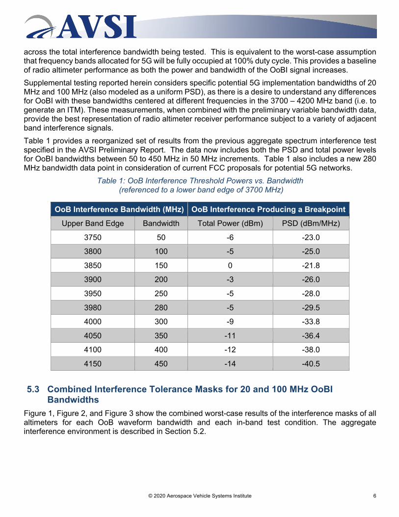
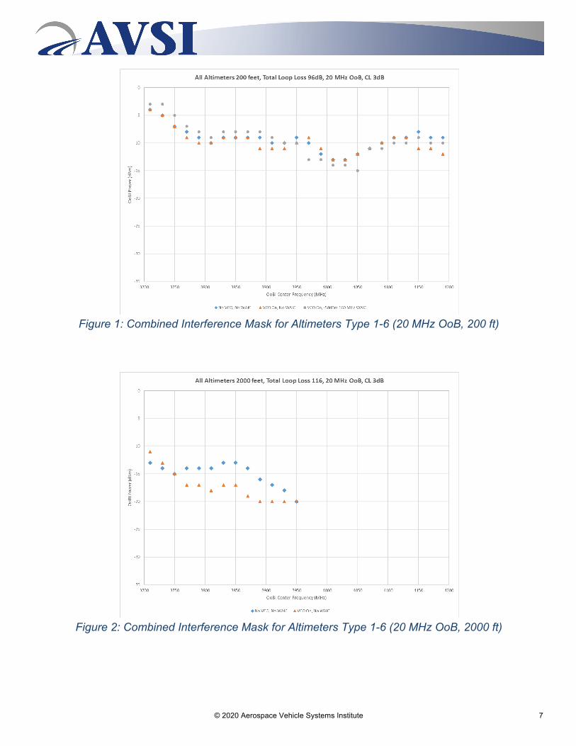
5.3 Combined Interference Tolerance Masks for 20 and 100 MHz OoBI Bandwidths
Figure 1, Figure 2, and Figure 3 show the combined worst-case results of the interference masks of all altimeters for each OoB waveform bandwidth and each in-band test condition. The aggregate interference environment is described in Section 5.2.
© 2020 Aerospace Vehicle Systems Institute 7
Figure 1: Combined Interference Mask for Altimeters Type 1-6 (20 MHz OoB, 200 ft)
Figure 2: Combined Interference Mask for Altimeters Type 1-6 (20 MHz OoB, 2000 ft)
© 2020 Aerospace Vehicle Systems Institute 8
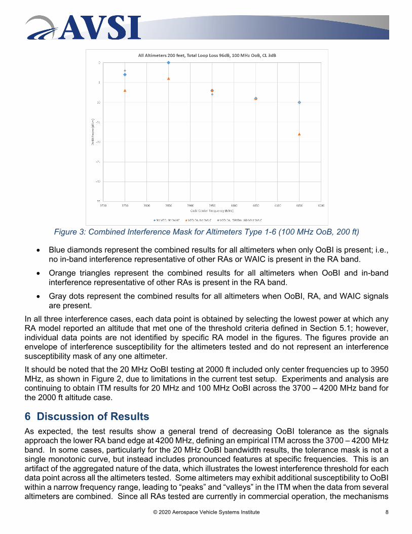
Figure 3: Combined Interference Mask for Altimeters Type 1-6 (100 MHz OoB, 200 ft)
• Blue diamonds represent the combined results for all altimeters when only OoBI is present; i.e., no in-band interference representative of other RAs or WAIC is present in the RA band.
• Orange triangles represent the combined results for all altimeters when OoBI and in-band interference representative of other RAs is present in the RA band.
• Gray dots represent the combined results for all altimeters when OoBI, RA, and WAIC signals are present.
In all three interference cases, each data point is obtained by selecting the lowest power at which any RA model reported an altitude that met one of the threshold criteria defined in Section 5.1; however, individual data points are not identified by specific RA model in the figures. The figures provide an envelope of interference susceptibility for the altimeters tested and do not represent an interference susceptibility mask of any one altimeter. It should be noted that the 20 MHz OoBI testing at 2000 ft included only center frequencies up to 3950 MHz, as shown in Figure 2, due to limitations in the current test setup. Experiments and analysis are continuing to obtain ITM results for 20 MHz and 100 MHz OoBI across the 3700 – 4200 MHz band for the 2000 ft altitude case.
6 Discussion of Results As expected, the test results show a general trend of decreasing OoBI tolerance as the signals approach the lower RA band edge at 4200 MHz, defining an empirical ITM across the 3700 – 4200 MHz band. In some cases, particularly for the 20 MHz OoBI bandwidth results, the tolerance mask is not a single monotonic curve, but instead includes pronounced features at specific frequencies. This is an artifact of the aggregated nature of the data, which illustrates the lowest interference threshold for each data point across all the altimeters tested. Some altimeters may exhibit additional susceptibility to OoBI within a narrow frequency range, leading to “peaks” and “valleys” in the ITM when the data from several altimeters are combined. Since all RAs tested are currently in commercial operation, the mechanisms
© 2020 Aerospace Vehicle Systems Institute 9
leading to specific spectral features in the combined plot do not change interpretation of the combined worst-case envelope represented by Figure 1 through Figure 3. Further, the difference in OoBI tolerance typically varies by only a few dB based on the presence of in-band interference signals, including both other RAs and WAIC, except when the OoBI signal is centered within 50 MHz of the lower RA band edge. This suggests that these existing in-band interference sources do not play a major role in determining the OoBI susceptibility of RAs. As stated above, the simulated WAIC interference levels for the 200 ft altitude tests were derived based on an assumed 6 dBm/MHz EIRP emissions limit for each WAIC-equipped aircraft in the WCLS. However, international standards defining WAIC emission limits are still being defined and are anticipated to be below this 6 dBm/MHz EIRP limit. Therefore, in practice the in-band interference from WAIC systems should be even less significant in characterizing RA susceptibility to OoBI. The observed lack of dependence of the OoBI tolerance on in-band interference is not unexpected; this result is reasonable when considering the likely interference mechanism in each case. For the in-band interference from RAs and WAIC, the interfering signals are at lower power levels, but may be contained directly within the intermediate frequency (IF) bandwidth of the victim RA receiver for at least part of each of the victim’s FMCW sweeps. Therefore, these signals contribute to an elevated noise level in the victim IF, thus resulting in receiver desensitization. For the OoBI, the interfering signals do not directly fall within the IF bandwidth of the victim RA, since they are well outside of the victim RA’s FMCW sweep bandwidth.18 Instead, given the relatively high power levels in excess of -20 dBm, the OoBI likely contributes to a receiver overload condition in the victim RA. Although these power levels are well below the actual saturation point of the RA receivers, any unanticipated nonlinearities in the receive signal chain in FMCW radars may produce erroneous targets. Therefore, “receiver overload” in this context refers not only to the traditional concern of gain compression, but also to the risk of harmonic distortion and intermodulation, which are known to cause detrimental effects to performance for typical RA designs. Another critical trend observed in the test results is the dependence of the OoBI tolerance on altitude, with the data collected at 2000 ft showing a decreased tolerance of about 8-10 dB relative to the 200 ft results. This is consistent with RA operation as they are much more sensitive at higher altitudes to account for increased path losses for the ground return signal. The OoBI tolerance may decrease further as test altitudes approach the maximum altitude measurement range for any of the RAs considered in this study (nearly 8000 ft), although further testing would be required to confirm this. It is anticipated that any additional decrease in OoBI tolerance at altitudes up to 8000 ft would likely be limited to no more than 6 dB relative to the 2000 ft results, based on typical RA sensitivity characteristics and the observed difference between the 200 ft and 2000 ft test cases. The 2000 ft test altitude was chosen since it is the highest that could be reliably simulated while remaining within the maximum measurement range of all RAs considered in this study.19 The test results provide additional validation to existing protection criteria for RAs. Recommendation ITU-R M.2059-0 provides operational characteristics and protection criteria for RAs such as those
18 Note that it is still possible for some of the OoBI signals to enter the victim’s IF bandwidth via the mixing products of
multiple subcarriers, which may also lead to receiver desensitization. However, this phenomenon would be highly dependent on specific RA receiver characteristics, and will thus not be discussed further here. The scope of this report is limited to black-box testing of RAs only.
19 Some of the RAs tested only measure altitude up to 2500 ft, which is the minimum specified upper limit. See ED-30 supra note 13.
© 2020 Aerospace Vehicle Systems Institute 10
considered in this study.20 Three separate protection criteria are described for three different interference mechanisms: receiver front-end overload, receiver desensitization, and false altitude reports.21 Of these, only the receiver overload criterion is directly applicable to the primary emissions from adjacent-band services (the other criteria are applicable only to the out-of-band and spurious emissions from such services). This criterion states that adjacent band emissions must stay below the stated overload thresholds for RAs, modified by a frequency dependent rejection (FDR) factor associated with a representative RF selectivity roll-off factor for RA receivers. This criterion can be applied to develop an alternate ITM for RAs in the 3700 – 4200 MHz band. Considering that the receiver overload criterion provided in Rec. M.2059 accounts for the worst-case operational conditions for RAs (e.g. tracking an altitude at the maximum measurement range, where the receiver is most sensitive), and an additional few dB of reduction in OoBI tolerance is expected for altitudes above 2000 ft, the test results generally provide good agreement with this protection criterion. This suggests that the protection criteria established in Rec. M.2059, along with the 6-10 dB ICAO safety margin for safety critical systems,22 can be used in future studies of specific 5G implementation scenarios. Finally, it must be noted that as in the AVSI Preliminary Test Report,23 Altimeter Type 7 exhibited a reduced OoBI tolerance threshold compared to the other six RAs tested, generally in the range of -30 to -27 dBm across the full 3700 – 4200 MHz band, with little or no frequency dependence. As such, the data from this altimeter was excluded from the combined ITM plots.
7 Conclusions The results described above provide a more complete baseline of radio altimeter performance when operating in the presence of new OoBI signals with transmission characteristics different than the current RF environment in the 3700 – 4200 MHz band. While the majority of radio altimeters demonstrate some resilience to OoBI, this does not guarantee absolute protection from any signals in the 3700 – 4200 MHz band. Therefore, RA performance and the respective operational requirements for safety in national airspace must be considered when establishing rules and operational characteristics for any new terrestrial mobile networks in the adjacent 3700 – 4200 MHz band. Protection criteria for RAs embodied in Rec. M.2059-0 provide the only existing guidance for changes in the RF environment within and adjacent to the 4200 – 4400 MHz frequency band. The data presented herein largely corroborate these criteria for the 3700 – 4200 MHz band and can be used to develop future rules and operational characteristics for new allocations in this frequency band. It must be understood that both the OoBI tolerance thresholds determined in this study and the protection criteria in Rec. M.2059 are stated in reference to the actual failure point of RAs, at which there is a certainty of erroneous behavior. Analyses which utilize these thresholds must also consider that RF interference is statistical in nature, and thus system integrity requirements may lead to allowable OoBI levels below the thresholds reported here. These conclusions are based on the data presented in this report, which were collected from altimeter models labeled Type 1 through Type 6 in the AVSI Preliminary Report. As stated above, altimeter Type 7 exhibited a reduced OoBI tolerance threshold compared to the other six RAs tested, and was excluded from the combined ITM plots in Section 5.3. Despite the difference in susceptibility to OoBI
20 International Telecommunication Union, ITU-R M.2059-0, Operational and technical characteristics and protection
criteria of radio altimeters utilizing the band 4200-4400 MHz (2014) (“M.2059-0”). 21 Ibid., pp 18-22. 22 ICAO, Doc 9718, Handbook on Radio Frequency Spectrum Requirements for Civil Aviation, Volume I “ICAO spectrum
strategy, policy statements and related information,” Second Edition (2018) at p. 9-8. 23 See AVSI Preliminary Report Section 4.4 “Commentary on Preliminary Results” at pp 19-20.
© 2020 Aerospace Vehicle Systems Institute 11
compared to the other altimeters tested, it is critical to state that Altimeter Type 7 is currently in use in certified aircraft and has thus demonstrated compliance with applicable radio altimeter minimum operational performance standards. Furthermore, this altimeter is known to be widely deployed in the cost-sensitive general aviation, lower-end business aviation and smaller helicopter market segments and sees substantial usage with a large installation base up to the present day. While AVSI acknowledges that this is not a comprehensive assessment of all potential variations and national implementations in the 3700 – 4200 MHz band, the information herein provides a foundation dataset for national regulators to use when analyzing the impact of new adjacent band services on RA performance and their safety functions. AVSI will continue testing and will report its complete findings on RA performance to ICAO in March 2020. AVSI invites additional comments and feedback to provide regulators with the best available data to ensure the continued safe operation of radio altimeters.