February 2013 Type 627F Pilot-Operated Pressure Reducing ... · Bulletin 71.2:627F 3 Figure 2. Type...
12
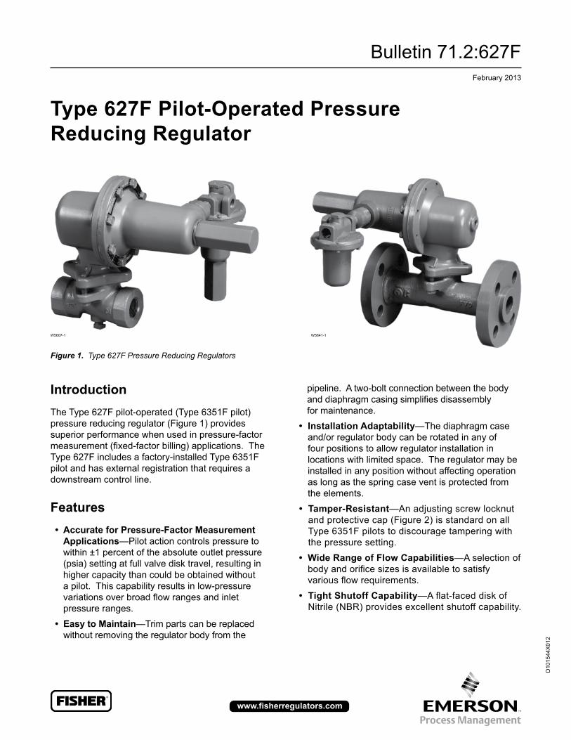
Bulletin 71.2:627F February 2013 D101544X012 www.fisherregulators.com Type 627F Pilot-Operated Pressure Reducing Regulator Introduction The Type 627F pilot-operated (Type 6351F pilot) pressure reducing regulator (Figure 1) provides superior performance when used in pressure-factor measurement (fixed-factor billing) applications. The Type 627F includes a factory-installed Type 6351F pilot and has external registration that requires a downstream control line. Features • Accurate for Pressure-Factor Measurement Applications—Pilot action controls pressure to within ±1 percent of the absolute outlet pressure (psia) setting at full valve disk travel, resulting in higher capacity than could be obtained without a pilot. This capability results in low-pressure variations over broad flow ranges and inlet pressure ranges. • Easy to Maintain—Trim parts can be replaced without removing the regulator body from the Figure 1. Type 627F Pressure Reducing Regulators pipeline. A two-bolt connection between the body and diaphragm casing simplifies disassembly for maintenance. • Installation Adaptability—The diaphragm case and/or regulator body can be rotated in any of four positions to allow regulator installation in locations with limited space. The regulator may be installed in any position without affecting operation as long as the spring case vent is protected from the elements. • Tamper-Resistant—An adjusting screw locknut and protective cap (Figure 2) is standard on all Type 6351F pilots to discourage tampering with the pressure setting. • Wide Range of Flow Capabilities—A selection of body and orifice sizes is available to satisfy various flow requirements. • Tight Shutoff Capability—A flat-faced disk of Nitrile (NBR) provides excellent shutoff capability. W5607-1 W5641-1
Transcript of February 2013 Type 627F Pilot-Operated Pressure Reducing ... · Bulletin 71.2:627F 3 Figure 2. Type...
Bulletin 71.2:627FFebruary 2013
D10
1544
X01
2
www.fisherregulators.com
Type 627F Pilot-Operated Pressure Reducing Regulator
IntroductionThe Type 627F pilot-operated (Type 6351F pilot) pressure reducing regulator (Figure 1) provides superior performance when used in pressure-factor measurement(fixed-factorbilling)applications.TheType 627F includes a factory-installed Type 6351F pilotandhasexternalregistrationthatrequiresadownstream control line.
Features • Accurate for Pressure-Factor Measurement
Applications—Pilot action controls pressure to within ±1 percent of the absolute outlet pressure (psia) setting at full valve disk travel, resulting in higher capacity than could be obtained without a pilot. This capability results in low-pressure variationsoverbroadflowrangesandinletpressure ranges.
• Easy to Maintain—Trim parts can be replaced without removing the regulator body from the
Figure 1. Type 627F Pressure Reducing Regulators
pipeline. A two-bolt connection between the body anddiaphragmcasingsimplifiesdisassemblyfor maintenance.
• Installation Adaptability—The diaphragm case and/or regulator body can be rotated in any of four positions to allow regulator installation in locations with limited space. The regulator may be installed in any position without affecting operation as long as the spring case vent is protected from the elements.
• Tamper-Resistant—An adjusting screw locknut and protective cap (Figure 2) is standard on all Type 6351F pilots to discourage tampering with the pressure setting.
• Wide Range of Flow Capabilities—A selection of bodyandorificesizesisavailabletosatisfyvariousflowrequirements.
• Tight Shutoff Capability—Aflat-faceddiskofNitrile(NBR)providesexcellentshutoffcapability.
W5607-1 W5641-1
Bulletin 71.2:627F
2
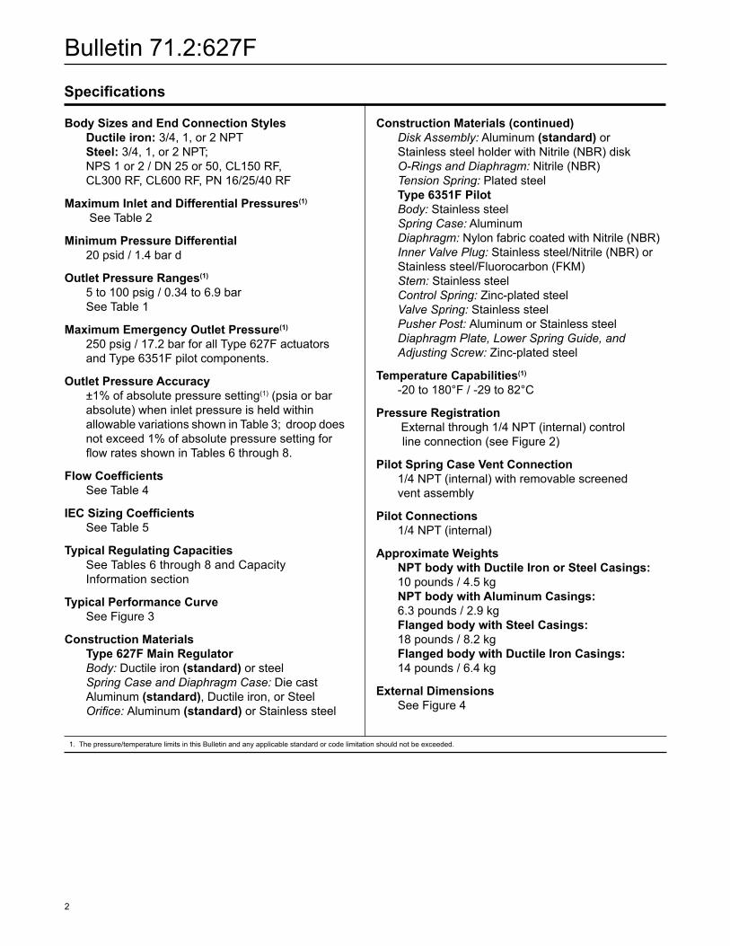
Body Sizes and End Connection Styles Ductile iron: 3/4, 1, or 2 NPT Steel: 3/4, 1, or 2 NPT; NPS 1 or 2 / DN 25 or 50, CL150 RF, CL300 RF, CL600 RF, PN 16/25/40 RF
Maximum Inlet and Differential Pressures(1)
See Table 2
Minimum Pressure Differential 20 psid / 1.4 bar d
Outlet Pressure Ranges(1)
5 to 100 psig / 0.34 to 6.9 bar See Table 1
Maximum Emergency Outlet Pressure(1)
250 psig / 17.2 bar for all Type 627F actuators and Type 6351F pilot components.
Outlet Pressure Accuracy ±1% of absolute pressure setting(1) (psia or bar absolute) when inlet pressure is held within allowable variations shown in Table 3; droop does notexceed1%ofabsolutepressuresettingfor flowratesshowninTables6through8.
Flow Coefficients See Table 4
IEC Sizing Coefficients See Table 5
Typical Regulating Capacities SeeTables6through8andCapacity Information section
Typical Performance Curve See Figure 3
Construction Materials Type 627F Main Regulator Body: Ductile iron (standard) or steel Spring Case and Diaphragm Case: Die cast Aluminum (standard), Ductile iron, or Steel Orifice:Aluminum (standard) or Stainless steel
1.Thepressure/temperaturelimitsinthisBulletinandanyapplicablestandardorcodelimitationshouldnotbeexceeded.
Specifications
Construction Materials (continued) Disk Assembly: Aluminum (standard) or Stainless steel holder with Nitrile (NBR) disk O-Rings and Diaphragm: Nitrile (NBR) Tension Spring: Plated steel Type 6351F Pilot Body: Stainless steel Spring Case: Aluminum Diaphragm: Nylon fabric coated with Nitrile (NBR) Inner Valve Plug: Stainless steel/Nitrile (NBR) or Stainless steel/Fluorocarbon (FKM) Stem: Stainless steel Control Spring: Zinc-plated steel Valve Spring: Stainless steel Pusher Post: Aluminum or Stainless steel Diaphragm Plate, Lower Spring Guide, and Adjusting Screw: Zinc-plated steel
Temperature Capabilities(1)
-20to180°F/-29to82°C
Pressure Registration Externalthrough1/4NPT(internal)control line connection (see Figure 2)
Pilot Spring Case Vent Connection 1/4 NPT (internal) with removable screened vent assembly
Pilot Connections 1/4 NPT (internal)
Approximate Weights NPT body with Ductile Iron or Steel Casings: 10 pounds / 4.5 kg NPT body with Aluminum Casings: 6.3 pounds / 2.9 kg Flanged body with Steel Casings: 18pounds/8.2kg Flanged body with Ductile Iron Casings: 14 pounds / 6.4 kg
External Dimensions See Figure 4

Bulletin 71.2:627F
3
Figure 2. Type 627F Pilot-Operated Pressure Reducing Regulator Operational Schematic
A6558
PILOT SUPPLY TUBING(FACTORY INSTALLATION OPTIONAL)
PILOT ADJUSTINGSCREW
FILTER(FACTORYINSTALLATIONOPTIONAL)
RESTRICTION(BLEED)
TENSIONSPRING
SPRING SEAT BOLT,THIS IS NOT ANADJUSTING SCREW
FIELD INSTALLEDDOWNSTREAMCONTROL LINE
PILOT DIAPHRAGM
TYPE 6351F PILOT
TYPE 627F REGULATOR
MAIN REGULATORDIAPHRAGM
LEVER
VALVEDISK
INLET PRESSURE OUTLET PRESSURE ATMOSPHERIC PRESSURE LOADING PRESSURE

Bulletin 71.2:627F
4
ORIFICE SIZEALLOWABLE INLET PRESSURE RANGE FOR MAINTAINING OUTLET PRESSURE WITHIN
±1% OF THE ABSOLUTE OUTLET PRESSURE SETTING(1)
5 psig / 0.34 bar 30 psig / 2.1 bar 40 psig / 2.8 bar 60 psig / 4.1 bar 100 psig / 6.9 bar
Inches mm psig bar psig bar psig bar psig bar psig bar
3/8x1/83/8x1/4
3/81/2
9.5x3.29.5x6.4
9.513
30 to 25030 to 25030 to 25025 to 125
2.1 to 17.22.1 to 17.22.1 to 17.21.7to8.6
55 to 25055 to 25055 to 25050 to 125
3.8to17.23.8to17.23.8to17.23.4to8.6
65 to 25065 to 25065 to 25060 to 125
4.5 to 17.24.5 to 17.24.5 to 17.24.1to8.6
85to25085to25085to25080to125
5.9 to 17.25.9 to 17.25.9 to 17.25.5to8.6
125 to 250125 to 250125 to 250120 to 125
8.6to17.28.6to17.28.6to17.28.3to8.6
1.Forbestperformance,outletpressuresettingshouldbemadeusinganinletpressurethatismidwaybetweenthehighestandlowestexpectedinletpressure.
Table 3.AdditionalSpecifications
ORIFICE SIZE MAXIMUM INLET PRESSURE MAXIMUM PRESSURE DIFFERENTIAL
Inches mm psig bar psi bar
3/8x1/83/8x1/4
3/81/2
9.5x3.29.5x6.4
9.513
250250250125
17.217.217.28.6
250250250125
17.217.217.28.6
Table 2. Maximum Allowable Inlet Pressures and Pressure Differential
Table 5. IECSizingCoefficients
PILOT TYPEOUTLET PRESSURE RANGE
PILOT CONTROL SPRING INFORMATION
Part Number Color CodeWire Diameter Free Length
psig bar Inches mm Inches mm
6351F 5 to 3535 to 100
0.34 to 2.42.4 to 6.9
1B7883270221K748527022
UnpaintedRed
0.1420.192
3.614.88
2.132.19
54.155.6
Table 1. Outlet Pressure Ranges
ORIFICE SIZE3/4 NPT BODY NPS 1 / DN 25 BODY NPS 2 / DN 50 BODY
Wide-Open Wide-OpenC1
Wide-Open Wide-OpenC1
Wide-Open Wide-OpenC1
Inches mm Cg Cv Cg Cv Cg Cv
3/8x1/8 9.5x3.2 12.5 0.43 29.1 12.5 0.43 29.4 12.5 0.43 29.2
3/8x1/4 9.5x6.4 50 1.63 30.6 50 1.71 29.3 52 1.66 31.3
3/8 9.5 108 2.99 36.1 108 3.42 31.6 115 3.39 33.9
1/2 13 190 4.87 39.0 190 5.29 35.9 200 5.01 39.9
ORIFICE SIZE XTFD FL
Inches mm 3/4 NPT body NPS 1 / DN 25 body NPS 2 / DN 50 body
1/8 3.2 0.54 0.55 0.54
0.50
0.79
1/4 6.4 0.59 0.54 0.62 0.87
3/8 9.5 0.82 0.63 0.73 0.89
1/2 13 0.96 0.82 1.01 0.86
Table 4.FlowCoefficients
Bulletin 71.2:627F
5
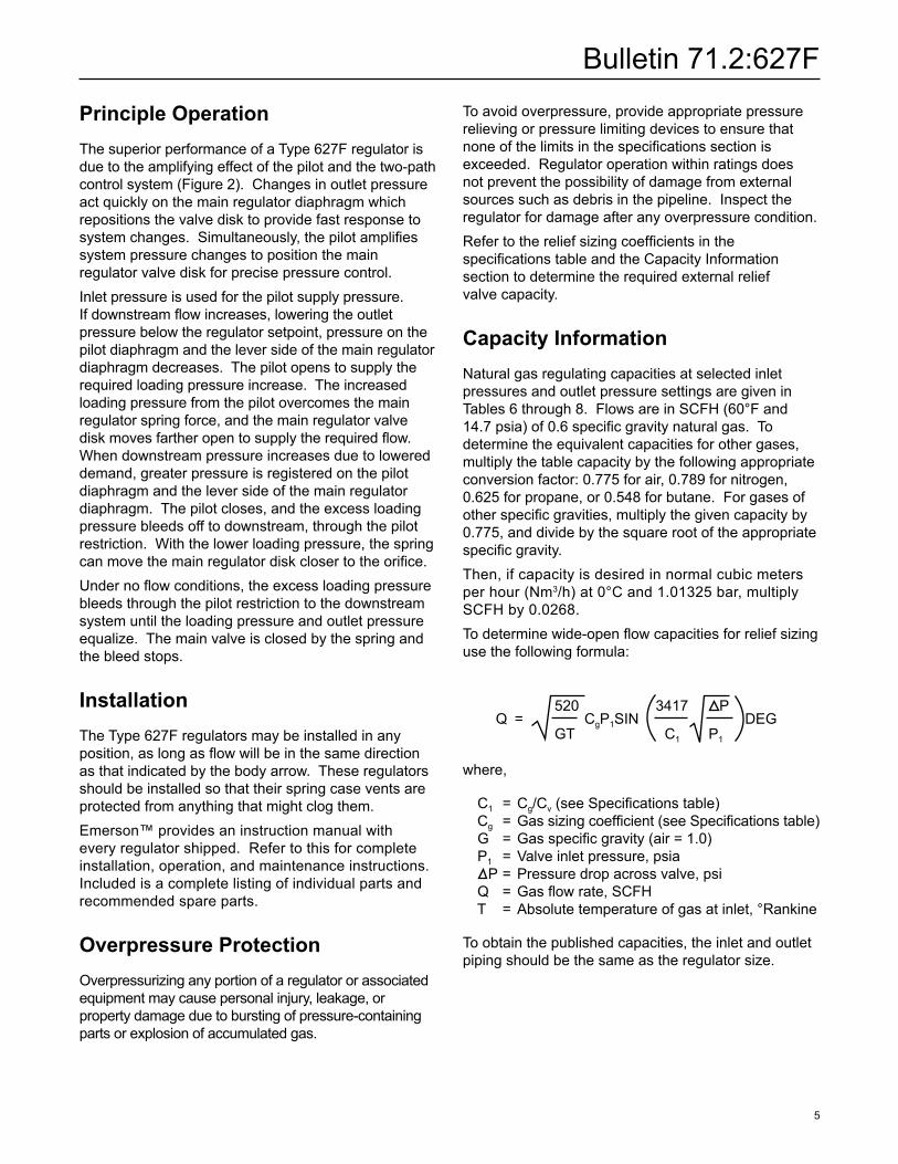
Principle OperationThe superior performance of a Type 627F regulator is due to the amplifying effect of the pilot and the two-path control system (Figure 2). Changes in outlet pressure actquicklyonthemainregulatordiaphragmwhichrepositions the valve disk to provide fast response to systemchanges.Simultaneously,thepilotamplifiessystem pressure changes to position the main regulator valve disk for precise pressure control.Inlet pressure is used for the pilot supply pressure. Ifdownstreamflowincreases,loweringtheoutletpressure below the regulator setpoint, pressure on the pilot diaphragm and the lever side of the main regulator diaphragm decreases. The pilot opens to supply the requiredloadingpressureincrease.Theincreasedloading pressure from the pilot overcomes the main regulator spring force, and the main regulator valve diskmovesfartheropentosupplytherequiredflow.When downstream pressure increases due to lowered demand, greater pressure is registered on the pilot diaphragm and the lever side of the main regulator diaphragm.Thepilotcloses,andtheexcessloadingpressure bleeds off to downstream, through the pilot restriction. With the lower loading pressure, the spring canmovethemainregulatordiskclosertotheorifice.Undernoflowconditions,theexcessloadingpressurebleeds through the pilot restriction to the downstream system until the loading pressure and outlet pressure equalize.Themainvalveisclosedbythespringandthe bleed stops.
InstallationThe Type 627F regulators may be installed in any position,aslongasflowwillbeinthesamedirectionas that indicated by the body arrow. These regulators should be installed so that their spring case vents are protected from anything that might clog them.Emerson™ provides an instruction manual with every regulator shipped. Refer to this for complete installation, operation, and maintenance instructions. Included is a complete listing of individual parts and recommended spare parts.
Overpressure ProtectionOverpressurizinganyportionofaregulatororassociatedequipmentmaycausepersonalinjury,leakage,orproperty damage due to bursting of pressure-containing partsorexplosionofaccumulatedgas.
To avoid overpressure, provide appropriate pressure relieving or pressure limiting devices to ensure that noneofthelimitsinthespecificationssectionisexceeded.Regulatoroperationwithinratingsdoesnotpreventthepossibilityofdamagefromexternalsources such as debris in the pipeline. Inspect the regulator for damage after any overpressure condition.RefertothereliefsizingcoefficientsinthespecificationstableandtheCapacityInformationsectiontodeterminetherequiredexternalreliefvalve capacity.
Capacity InformationNatural gas regulating capacities at selected inlet pressures and outlet pressure settings are given in Tables6through8.FlowsareinSCFH(60°Fand14.7psia)of0.6specificgravitynaturalgas.Todeterminetheequivalentcapacitiesforothergases,multiply the table capacity by the following appropriate conversionfactor:0.775forair,0.789fornitrogen,0.625forpropane,or0.548forbutane.Forgasesofotherspecificgravities,multiplythegivencapacityby0.775,anddividebythesquarerootoftheappropriatespecificgravity.Then, if capacity is desired in normal cubic meters per hour (Nm3/h)at0°Cand1.01325bar,multiplySCFHby0.0268.Todeterminewide-openflowcapacitiesforreliefsizinguse the following formula:
where,
C1 = Cg/Cv(seeSpecificationstable) Cg =Gassizingcoefficient(seeSpecificationstable) G =Gasspecificgravity(air=1.0) P1 = Valve inlet pressure, psia P = Pressure drop across valve, psi Q =Gasflowrate,SCFH T =Absolutetemperatureofgasatinlet,°Rankine
To obtain the published capacities, the inlet and outlet pipingshouldbethesameastheregulatorsize.
Q = CgP1SIN DEG520 3417 P
GT C1 P1
Bulletin 71.2:627F
6
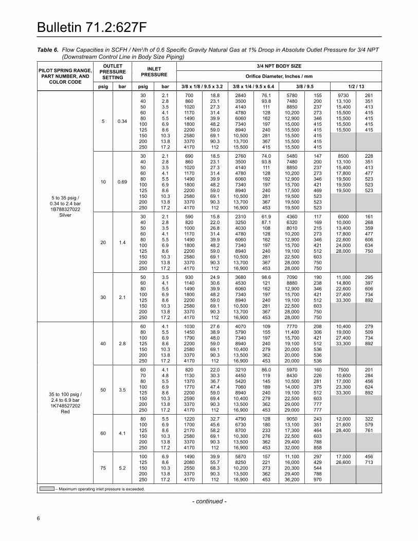
Table 6. Flow Capacities in SCFH / Nm3/hof0.6SpecificGravityNaturalGasat1%DroopinAbsoluteOutletPressurefor3/4NPT(Downstream Control Line in Body Size Piping)
- continued -
PILOT SPRING RANGE, PART NUMBER, AND
COLOR CODE
OUTLETPRESSURE
SETTING
INLETPRESSURE
3/4 NPT BODY SIZE
Orifice Diameter, Inches / mm
psig bar psig bar 3/8 x 1/8 / 9.5 x 3.2 3/8 x 1/4 / 9.5 x 6.4 3/8 / 9.5 1/2 / 13
5 to 35 psig / 0.34 to 2.4 bar1B788327022
Silver
5 0.34
3040506080
100125150200250
2.12.83.54.15.56.98.6
10.313.817.2
700860
10201170149018002200258033704170
18.823.127.331.439.948.259.069.190.3112
2840350041404780606073408940
10,50013,70015,500
76.193.8111128162197240281367415
578074808850
10,20012,90015,00015,50015,50015,50015,500
155 200237273346415 415415415415
973013,10015,40015,50015,50015,50015,500
261351413415415 415415
10 0.69
3040506080
100125150200250
2.12.83.54.15.56.98.6
10.313.817.2
690860
10201170149018002200 25803370 4170
18.523.127.331.439.948.259.069.190.3112
2760350041404780606073408940
10,50013,70016,900
74.093.8111128192197240281367453
548074808850
10,20012,90015,70017,50019,50019,50019,500
147200237273346421469523523523
850013,10015,40017,80019,50019,50019,500
228351413477523523523
20 1.4
3040506080
100125150200250
2.12.83.54.15.56.98.6
10.313.817.2
590820
10001170149018002200258033704170
15.822.026.831.439.948.259.069.190.3112
2310325040304780606073408940
10,50013,70016,900
61.987.1108128162197240281367453
436063208010
10,20012,90015,70019,10022,50028,00028,000
117 169215273346421512603750750
600010,00013,40017,80022,60024,00028,000
161268359477606634750
30 2.1
506080
100125150200250
3.54.15.56.98.6
10.313.817.2
9301140149018002200258033704170
24.930.639.948.259.069.190.3112
36804530606073408940
10,50013,70016,900
98.6121162197240281367453
70908880
12,90015,70019,10022,50028,00028,000
190238346421512603750750
11,00014,80022,60027,40033,300
295397606734892
35 to 100 psig / 2.4 to 6.9 bar1K748527202
Red
40 2.8
6080
100125150200250
4.15.56.98.6
10.313.817.2
1030145017902200258033704170
27.638.948.059.069.190.3112
4070579073408940
10,40013,50016,900
109155197240279362453
777011,40015,70019,10020,00020,00020,000
208306421512536536536
10,40019,00027,40033,300
279509734892
50 3.5
607080
100125150200250
4.14.85.56.98.6
10.313.817.2
8201130137017702200259033704170
22.030.336.747.459.069.490.3112
32104450542070608940
10,40013,50016,900
86.0119145189240279362453
59708430
10,50014,00019,10022,50029,00029,000
160226281375512603777777
750010,60017,00023,30033,300
201284456624892
60 4.1
80100125150200250
5.56.98.6
10.313.817.2
122017002170258033704170
32.745.658.269.190.3112
479067308700
10,30013,50016,900
128180233276362453
905013,10017,30022,50029,40032,000
243351464603788858
12,00021,60028,400
322579761
75 5.2
100125150200250
6.98.6
10.313.817.2
14902080255033704170
39.955.768.390.3112
58708250
10,20013,50016,900
157221273362453
11,10016,00020,30029,40036,200
297429544788970
17,00026,600
456713
–Maximumoperatinginletpressureisexceeded.

Bulletin 71.2:627F
7
Table 6. Flow Capacities in SCFH / Nm3/hof0.6SpecificGravityNaturalGasat1%DroopinAbsoluteOutletPressurefor3/4NPT(Downstream Control Line in Body Size Piping) (continued)
Table 7. Flow Capacities in SCFH / Nm3/hof0.6SpecificGravityNaturalGasat1%DroopinAbsoluteOutletPressureforNPS1/DN25(Downstream Control Line in Body Size Piping)
- continued -
PILOT SPRING RANGE, PART NUMBER, AND
COLOR CODE
OUTLETPRESSURE
SETTING
INLETPRESSURE
3/4 NPT BODY SIZE
Orifice Diameter, Inches / mm
psig bar psig bar 3/8 x 1/8 / 9.5 x 3.2 3/8 x 1/4 / 9.5 x 6.4 3/8 / 9.5 1/2 / 13
35 to 100 psig / 2.4 to 6.9 bar1K748527202
Red
100 6.9
125150200250
8.610.313.817.2
1660236033304170
44.563.389.2112
66809320
13,40016,900
179250359453
12,50017,90026,60036,200
335480713970
18,000 482
–Maximumoperatinginletpressureisexceeded.
PILOT SPRING RANGE, PART NUMBER, AND
COLOR CODE
OUTLETPRESSURE
SETTING
INLETPRESSURE
NPS 1 / DN 25 BODY SIZE
Orifice Diameter, Inches / mm
psig bar psig bar 3/8 x 1/8 / 9.5 x 3.2 3/8 x 1/4 / 9.5 x 6.4 3/8 / 9.5 1/2 / 13
5 to 35 psig / 0.34 to 2.4 bar 1B788327022
Silver
5 0.34
3040506080
100125150200250
2.12.83.54.15.56.98.6
10.313.817.2
700860
10201170149018002200258033704170
18.823.127.331.439.948.259.069.190.3112
2840350041404780606073408940
10,50013,70016,900
76.193.8111128162197240281367453
604074808850
10,20012,90015,70018,50018,50018,50018,500
162200237273346421496496496496
10,10013,10015,40017,80018,50018,50018,500
271351413477496 496496
10 6.9
3040506080
100125150200250
2.12.83.54.15.56.98.6
10.313.817.2
690860
10201170149018002200258033704170
18.523.127.331.439.948.259.069.190.3112
2760350041404780606073408940
10,50013,70016,900
74.093.8111128162197240281367453
584074808850
10,20012,90015,70019,10022,50022,60022,600
157200237273346421512603606606
893013,10015,40017,80022,60022,60022,600
239351413477606606606
20 1.4
3040506080
100125150200250
2.12.83.54.15.56.98.6
10.313.817.2
590820
10001170149018002200258033704170
15.822.026.831.439.948.259.069.190.3112
2310325040304780606073408940
10,50013,70016,900
61.987.1108128162197240281367453
482068308500
10,20012,90015,70019,10022,50029,40033,300
129183228273346421512603788892
640010,50013,40017,80022,60027,40033,300
172281359477606734892
30 2.1
506080
100125150200250
3.54.15.56.98.6
10.313.817.2
9301140149018002200258033704170
24.930.639.948.259.069.190.3112
36804530606073408940
10,50013,70016,900
98.6121162197240281367453
77209540
12,90015,70019,10022,50029,40036,200
207256346421512603788970
11,70015,60022,60027,40033,300
314418606734892
35 to 100 psig / 2.4 to 6.9 bar1K748527202
Red
40 2.8
6080
100125150200250
4.15.56.98.6
10.313.817.2
1030145017902200258033704170
27.638.948.059.069.190.3112
4070579073408940
10,40013,50016,900
109155197240279362453
853012,20015,70019,10022,50029,40036,200
229327421512603788970
11,00020,00027,40033,300
300536734892
–Maximumoperatinginletpressureisexceeded.

Bulletin 71.2:627F
8
Table 8. Flow Capacities in SCFH / Nm3/hof0.6SpecificGravityNaturalGasat1%DroopinAbsoluteOutletPressureforNPS2/DN50(Downstream Control Line in Body Size Piping)
Table 7. Flow Capacities in SCFH / Nm3/hof0.6SpecificGravityNaturalGasat1%DroopinAbsoluteOutletPressureforNPS1/DN25(Downstream Control Line in Body Size Piping) (continued)
PILOT SPRING RANGE, PART NUMBER, AND
COLOR CODE
OUTLETPRESSURE
SETTING
INLETPRESSURE
NPS 1 / DN 25 BODY SIZE
Orifice Diameter, Inches / mm
psig bar psig bar 3/8 x 1/8 / 9.5 x 3.2 3/8 x 1/4 / 9.5 x 6.4 3/8 / 9.5 1/2 / 13
35 to 100 psig / 2.4 to 6.9 bar1K748527202
Red
50 3.4
7080
100125150200250
4.85.56.98.6
10.313.817.2
1130137017702200259033704170
30.336.747.459.069.490.3112
4450542070608940
10,40013,50016,900
119145189240279362453
930011,40014,90019,10022,50029,40036,200
249306399512603788970
11,20018,30024,40033,300
300490654892
60 4.1
80100125150200250
5.56.98.6
10.313.817.2
122017002170258033704170
82.745.658.269.190.3112
479067308700
10,30013,50016,900
128180233276362453
10,00014,20018,40022,50029,40036,200
268381 493603788970
12,90022,90030,300
346614812
75 5.2
100125150200250
6.98.6
10.313.817.2
14902080255033704170
39.955.768.390.3112
58708250
10,20013,50016,900
157221273362453
12,30016,90020,30029,40036,200
330453544788970
18,00028,100
482753
100 6.9
125150200250
8.610.313.817.2
1660236033304170
44.563.389.2112
66809320
13,40016,900
179250359453
13,90020,00028,30036,200
373536758970
19,400 520
–Maximumoperatinginletpressureisexceeded.
PILOT SPRING RANGE, PART NUMBER, AND
COLOR CODE
OUTLETPRESSURE
SETTING
INLETPRESSURE
NPS 2 / DN 50 BODY SIZE
Orifice Diameter, Inches / mm
psig bar psig bar 3/8 x 1/8 / 9.5 x 3.2 3/8 x 1/4 / 9.5 x 6.4 3/8 / 9.5 1/2 / 13
5 to 35 psig / 0.34 to 2.4 bar1B788327022
Silver
5 0.34
3040506080
100125150200250
2.12.83.54.15.56.98.6
10.313.817.2
700860
10201170149018002200258033704170
18.823.127.331.439.948.259.069.190.3112
2840350041404780606073408940
10,50013,70016,900
76.193.8111128162197240281367453
615077609180
10,60013,40016,30019,80023,40030,00030,000
165208246284359437531627804804
10,10013,80016,30018,80023,80028,90030,000
271370437504638775804
10 0.69
3040506080
100125150200250
2.12.83.54.15.56.98.6
10.313.817.2
690860
10201170149018002200258033704170
18.523.127.331.439.948.259.069.190.3112
2760350041404780606073408940
10,50013,70016,900
74.093.8111128162197240281367453
587077609130
10,60013,40016,30019,80023,40030,50037,600
1572082462843594375316278171008
950013,80016,30018,80023,80028,90035,100
255370437504638775941
20 1.4
3040506080
100125150200250
2.12.83.54.15.56.98.6
10.313.817.2
590820
10001170149018002200258033704170
15.822.026.831.439.948.259.069.190.3112
2310325040304780606073408940
10,50013,70016,900
61.997.1108128162197240281367453
475068208570
10,60013,40016,30019,80023,40030,50037,600
1271832302843594375316278171008
700010,90013,90018,80023,80028,90035,100
188292373410638775941
–Maximumoperatinginletpressureisexceeded.
- continued -
Bulletin 71.2:627F
9
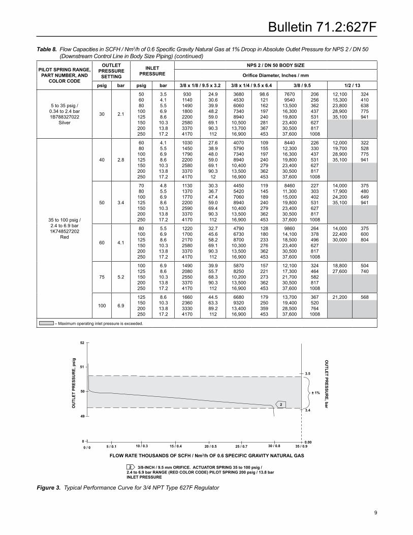
Table 8. Flow Capacities in SCFH / Nm3/hof0.6SpecificGravityNaturalGasat1%DroopinAbsoluteOutletPressureforNPS2/DN50(Downstream Control Line in Body Size Piping) (continued)
Figure 3.TypicalPerformanceCurvefor3/4NPTType627FRegulator
2 3/8-INCH / 9.5 mm ORIFICE. ACTUATOR SPRING 35 to 100 psig / 2.4 to 6.9 bar RANGE (RED COLOR CODE) PILOT SPRING 200 psig / 13.8 bar INLET PRESSURE
FLOW RATE THOUSANDS OF SCFH / Nm3/h OF 0.6 SPECIFIC GRAVITY NATURAL GAS
OU
TLET
PR
ESSU
RE,
psi
g
52
49
50
51
0
0 / 0 5 / 0.1 25 / 0.7 35 / 0.930 / 0.820 / 0.515 / 0.410 / 0.3
OU
TLET PRESSU
RE, bar
3.5
± 1%
0.00
3.42
PILOT SPRING RANGE, PART NUMBER, AND
COLOR CODE
OUTLETPRESSURE
SETTING
INLETPRESSURE
NPS 2 / DN 50 BODY SIZE
Orifice Diameter, Inches / mm
psig bar psig bar 3/8 x 1/8 / 9.5 x 3.2 3/8 x 1/4 / 9.5 x 6.4 3/8 / 9.5 1/2 / 13
5 to 35 psig / 0.34 to 2.4 bar1B788327022
Silver
30 2.1
506080
100125150200250
3.54.15.56.98.6
10.313.817.2
9301140149018002200258033704170
24.930.639.948.259.069.190.3112
36804530606073408940
10,50013,70016,900
98.6121162197240281367453
76709540
13,50016,30019,80023,40030,50037,600
2062563624375316278171008
12,10015,30023,80028,90035,100
324410638775941
35 to 100 psig / 2.4 to 6.9 bar 1K748527202
Red
40 2.8
6080
100125150200250
4.15.56.98.6
10.313.817.2
1030145017902200258033704170
27.638.948.059.069.190.312
4070579073408940
10,40013,50016,900
109155197240279362453
844012,30016,30019,80023,40030,50037,600
2263304375316278171008
12,00019,70028,90035,100
322528775941
50 3.4
7080
100125150200250
4.85.56.98.6
10.313.817.2
1130137017702200259033704170
30.336.747.459.069.490.3112
4450542070608940
10,40013,50016,900
119145189240279362453
846011,30015,00019,80023,40030,50037,600
2273034025316278171008
14,00017,90024,20035,100
375480649941
60 4.1
80100125150200250
5.56.98.6
10.313.817.2
122017002170258033704170
32.745.658.269.190.3112
479067308700
10,30013,50016,900
128180233276362453
986014,10018,50023,40030,50037,600
2643784966278171008
14,00022,40030,000
375600804
75 5.2
100125150200250
6.98.6
10.313.817.2
14902080255033704170
39.955.768.390.3112
58708250
10,20013,50016,900
157221273362453
12,10017,30021,70030,50037,600
3244645828171008
18,80027,600
504740
100 6.9
125150200250
8.610.313.817.2
1660236033304170
44.563.389.2112
66809320
13,40016,900
179250359453
13,70019,40028,50037,600
3675207641008
21,200 568
–Maximumoperatinginletpressureisexceeded.

Bulletin 71.2:627F
10
Figure 4. Dimensions
10.5 / 267
5.50 / 140
1.00 / 25.4
TYPE 6351FTYPE P594-1 FILTER (OPTIONAL)
12B2138_E
8.06 / 205
Ø 4.69 / 119
A
B
G D
BODY SIZE END CONNECTIONSTYLE
DIMENSIONS, Inches / mm
A B D F GInches DN
3/4 - - - - NPT 4.06 103 1.94 49 6.75 171 - - - - - - - - 2.00 51
1 - - - - NPT 4.06 103 1.94 49 6.75 171 - - - - - - - - 2.00 51
1 25
CL150 RF 7.25 184 3.62 92
6.75 171 4.38 111
2.12 54
CL300 RF 7.75 197 3.88 99 2.44 62
CL600 RF 8.25 210 4.12 105 2.44 62
PN 16/25/40 7.80 198 3.90 99 2.31 59
2 50
NPT 5.00 127 2.50 64 7.12 181 - - - - - - - - 2.62 67
CL150 RF 10.00 254 5.00 127
7.12 181 4.75 121
3.00 76
CL300 RF 10.50 267 5.25 133 3.25 83
CL600 RF 11.25 286 5.62 143 3.25 83
PN 16/25/40 10.31 262 5.16 131 3.25 83
9.12 / 232
5.50 / 140
1/4 NPT SUPPLY CONNECTION WITH OPTIONAL TYPE P594-1 FILTER
F
DG
TYPE 6351F
8.06 / 205
Ø 4.69 / 119
A
B
INCHES / mm12B7144_C
Table 9. Dimensions
Bulletin 71.2:627F
11
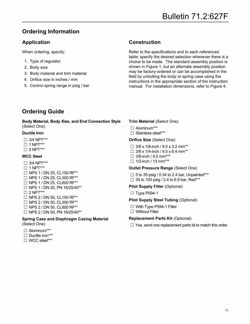
Ordering Guide Body Material, Body Size, and End Connection Style(Select One)Ductile Iron 3/4 NPT*** 1 NPT*** 2 NPT***WCC Steel 3/4 NPT*** 1 NPT*** NPS 1 / DN 25, CL150 RF** NPS 1 / DN 25, CL300 RF** NPS 1 / DN 25, CL600 RF** NPS 1 / DN 25, PN 16/25/40** 2 NPT*** NPS 2 / DN 50, CL150 RF** NPS 2 / DN 50, CL300 RF** NPS 2 / DN 50, CL600 RF** NPS 2 / DN 50, PN 16/25/40**Spring Case and Diaphragm Casing Material (Select One) Aluminum*** Ductile iron*** WCC steel***
Trim Material (Select One) Aluminum*** Stainless steel***Orifice Size (Select One) 3/8x1/8-inch/9.5x3.2mm** 3/8x1/4-inch/9.5x6.4mm** 3/8-inch/9.5mm*** 1/2-inch / 13 mm***Outlet Pressure Range (Select One) 5 to 35 psig / 0.34 to 2.4 bar, Unpainted*** 35 to 100 psig / 2.4 to 6.9 bar, Red***Pilot Supply Filter (Optional) Type P594-1Pilot Supply Steel Tubing (Optional) With Type P594-1 Filter Without FilterReplacement Parts Kit (Optional) Yes, send one replacement parts kit to match this order.
Ordering Information
Application
When ordering, specify:
1. Type of regulator 2.Bodysize 3. Body material and trim material 4.Orificesizeininches/mm 5. Control spring range in psig / bar
Construction
Refertothespecificationsandtoeachreferencedtable; specify the desired selection whenever there is a choice to be made. The standard assembly position is shown in Figure 1, but an alternate assembly position may be factory-ordered or can be accomplished in the fieldbyunboltingthebodyorspringcaseusingtheinstructions in the appropriate section of the instruction manual. For installation dimensions, refer to Figure 4.

Bulletin 71.2:627F
©Emerson Process Management Regulator Technologies, Inc., 1990, 2013; All Rights Reserved
The Emerson logo is a trademark and service mark of Emerson Electric Co. All other marks are the property of their prospective owners. Fisher is a mark owned by Fisher Controls International LLC, a business of Emerson Process Management.
The contents of this publication are presented for informational purposes only, and while every effort has been made to ensure their accuracy, they are not to be construed as warranties or guarantees,expressorimplied,regardingtheproductsorservicesdescribedhereinortheiruseorapplicability.Wereservetherighttomodifyorimprovethedesignsorspecificationsofsuchproducts at any time without notice.
Emerson Process Management Regulator Technologies Inc. does not assume responsibility for the selection, use or maintenance of any product. Responsibility for proper selection, use and maintenance of any Emerson Process Management Regulator Technologies Inc. product remains solely with the purchaser.
Industrial Regulators
Emerson Process Management Regulator Technologies, Inc.
USA-HeadquartersMcKinney,Texas75069-1872,USATel:+18005585853OutsideU.S.+19725483574
Asia-PacificShanghai 201206, ChinaTel:+862128929000
EuropeBologna 40013, ItalyTel: +39 051 419 0611
Middle East and AfricaDubai, United Arab EmiratesTel:+97148118100
Natural Gas Technologies
Emerson Process ManagementRegulator Technologies, Inc.
USA-HeadquartersMcKinney,Texas75069-1872,USATel:+18005585853OutsideU.S.+19725483574
Asia-PacificSingapore128461,SingaporeTel:+6567708337
EuropeBologna 40013, ItalyTel: +39 051 419 0611Chartres28008,FranceTel: +33 2 37 33 47 00
TESCOM
Emerson Process ManagementTescom Corporation
USA-HeadquartersElk River, Minnesota 55330-2445, USATels:+17632413238 +18004471250
EuropeSelmsdorf 23923, GermanyTel:+493882331287
Asia-PacificShanghai 201206, ChinaTel:+862128929499
For further information visit www.fisherregulators.com
Specification WorksheetApplication:SpecificUseLineSizeGasTypeandSpecificGravityGas TemperatureDoestheApplicationRequireOverpressureProtection? Yes No If yes, which is preferred: Relief Valve Monitor Regulator Shutoff DeviceIsoverpressureprotectionequipmentselectionassistancedesired?
Pressure:MaximumInletPressure(P1max)Minimum Inlet Pressure (P1min)Downstream Pressure Setting(s) (P2)MaximumFlow(Qmax)
Performance Required:AccuracyRequirements?NeedforExtremelyFastResponse?
Other Requirements:
Regulators Quick Order Guide* * * Readily Available for Shipment
* * Allow Additional Time for Shipment
* Special Order, Constructed from Non-Stocked Parts. ConsultYourlocalSalesOfficeforAvailability.
Availability of the product being ordered is determined by the component with the longestshippingtimefortherequestedconstruction.