FEB ig - data.bsee.gov · rhree Mai - non LeTourneau Series PCM-120AS, ... One MANITOWOC. 35...
64
In Reply Rtftr To: RP-2-1 I 4 JOG Placid 011 Conpany At Unt 1 on: Mr. Janes E. Jordan 3900 Thanksgiving Tower Dalits. Texts 75201 "•eetlasMMi Relerence Is suide to your Initial Plen of Exploration received January 21. :«**• for Lease OCS-G 7334. Block A-450. High Island Area. This pita includes tht activities proposed for bells A. 8. aad C. Ia accoidaa-.e with 30 CFR 250.34, revised Deceaber 13. 1979. and our letter dated January 29. 1979. this plan has been determined to »>a coat) tke ts of February 14. 1986. aid Is now being considered for approvel. Tour elan control nueber 1s K-2394 and should be referenced In your cossMinlcttlon tsd correspondence concerning tMs plen. Sincerely yours. (Orig. Sgd.) A. Oonald Giroir Acting Regional Supervisor Rules anu Production bcc: Lease OCS-G 7334 ((YS-3-2) (FILE ROOM) C0PS-3-4 u/J&aUlcJ/ifj^opy of the plan fPUBL.REC.) NJTolbtrt:gcw:2/7/86 Dlsv la o-OffJcaof FEB ig 1986
Transcript of FEB ig - data.bsee.gov · rhree Mai - non LeTourneau Series PCM-120AS, ... One MANITOWOC. 35...
In Reply Rtftr To: RP-2-1 I 4 JOG
Placid 011 Conpany At Unt 1 on: Mr. Janes E. Jordan 3900 Thanksgiving Tower Dalits. Texts 75201
"•eetlasMMi
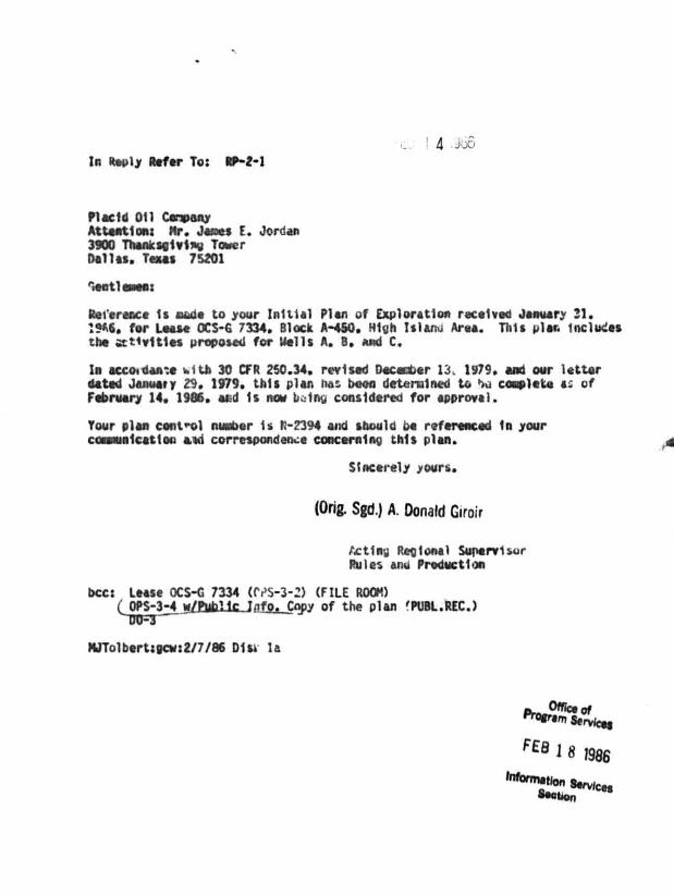
Relerence Is suide to your Initial Plen of Exploration received January 21. :«**• for Lease OCS-G 7334. Block A-450. High Island Area. This pita includes tht activities proposed for bells A. 8. aad C.
Ia accoidaa-.e with 30 CFR 250.34, revised Deceaber 13. 1979. and our letter dated January 29. 1979. this plan has been determined to »>a coat) tke ts of February 14. 1986. aid Is now being considered for approvel.
Tour elan control nueber 1s K-2394 and should be referenced In your cossMinlcttlon tsd correspondence concerning tMs plen.
Sincerely yours.
(Orig. Sgd.) A. Oonald Giroir
Acting Regional Supervisor Rules anu Production
bcc: Lease OCS-G 7334 ((YS-3-2) (FILE ROOM) C0PS-3-4 u/J&aUlcJ/ifj^opy of the plan fPUBL.REC.)
NJTolbtrt:gcw:2/7/86 Dlsv la
o-OffJcaof
FEB ig 1986
PLACID OIL COMPANY 3900 THANKSGIVING TOWER
DALLAS, TEXAS 75201 January 30, 1986
Minerals Management Service U. S. Department of the I n t e r i o r P.O. Box 7944 Metairie, LA 70010
Attention: Mr. Donald W. Solanas
MINERALS MANAGEMENT SERVICE.
JAN 31 1986
RE: Explora to ry D r i l l i n g Plan rPOdCTCTJ OCS-G-7334 Block A-450, High Island Area Offshore, Texas
Dear Mr. Sol nas:
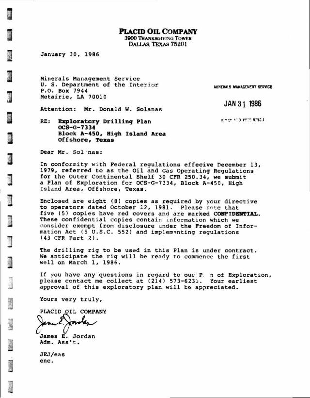
In conformity with Federal regulations e f f e c i v e December 13, 1979, r e f e r r e d to as the O i l and Gas Operating Regulations for the Outer Continental Shelf 30 CFR 250.34, we submit a Plan of Exploration f o r OCS-G-7334, Block A-450, High Island Area, Offshore, Texas.
Enclosed are eight (8) copies as required by your directive to operators dated October 22, 1981. Please note that five (5) copies have red covers and are marked CONFIDENTIAL. These confidential copies contain information which we consider exempt from disclosure under the Freedom of Information Act (5 U.S.C. 552) and implementing regulations (43 CFR Part 2).
The d r i l l i n g r i g to be used i n t h i s Plan i s under contract. We a n t i c i p a t e the r i g w i l l be ready to commence the f i r s t w e ll on March 1, 1986.
I f you have any questions i n regard to our P n of Exploration, please contact me c o l l e c t at (214) 573-623j. Your e a r l i e s t approval of t h i s exploratory plan w i l l b& appreciated.
Yours very t r u l y ,
PLACID OIL COMPANY
James E. Jordan Adm. Ass't.
JEJ/eas enc.
PLACID OIL COMPANY
EXPLORATORY DRILLING PLAN
OCS-G-7334
BLOCK A-450
HIGH ISLAND AREA
OFFSHORE, TEXAS

COWTBIfTS
General Information
Exhibit I Exploratory d r i l l i n g Schedule
Exhibit I I Location and V i c i n i t y Maps
Exhibit I I I D r i l l i n g Prognosis
Exhibit IV Rig 59 Specifications
Exhibit V D r i l l i n g Mud Components
Exhibit VI Diverter Hookup
Exhibit V I I Contingency Plan
Exhibit V I I I Shallow Hazard and C u l t u r a l
Exhibit IX
•Exhibit X
•Exhibit XI
•Confidential Information
Resources Report
Information on Gaseouc Emissions
Seismic Map
Geological Prognosis
GENERAL INFORMATION
Placid O i l Company proposes to commence d r i l l i n g operations
on Block A-4 50, High Island Area, i n the offshore waters of
Texas.
The block, consisting of 5,760 acres, was acquired by Texaco,
Inc., at the July 18, 1984, OCS Sale. Placid O i l Company
acquired Lease OCS-G-7 334 as a farm-in during the month of
January, 1986. The present ownership i s 100.00% Placid O i l
Company.
The purpose of t h i s exploratory plan i s t o evaluate the p o t e n t i a l
of lease OCS-G-7334 t o produce commercial amounts of hydrocarbons.
A d d i t i o n a l l y , the exploratory d r i l l i n g w i l l provide the necessary
geological and engineering data to plan f u r t h e r development
and production operations i f commercial hydrocarbons are present.
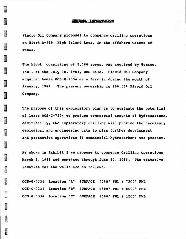
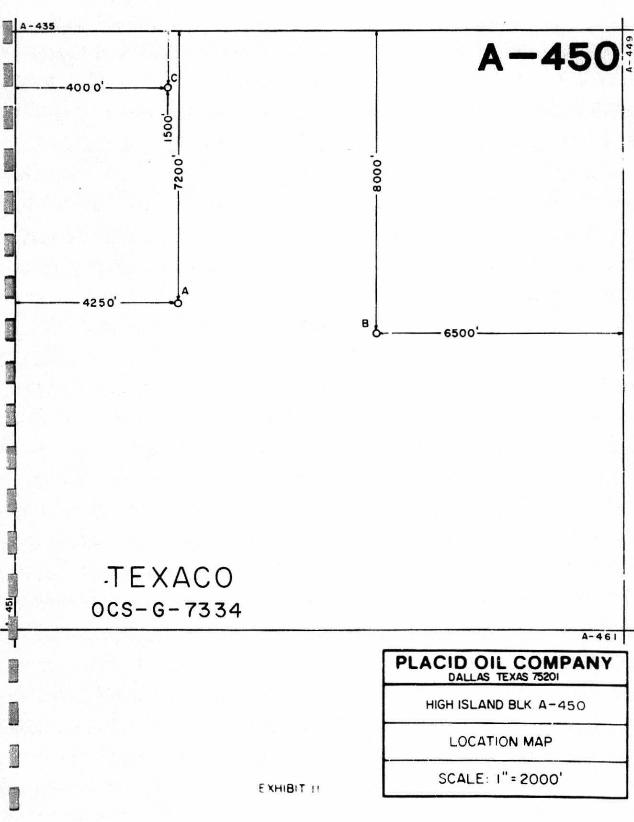
As shown i n Exhibit I we propose to commence d r i l l i n g operations
March 1, 1986 and continue through June 13, 1986. The t e n t a t i v e
l o c a t i o n f o r the wells are as follows:
OCS-G-7334 Location "A" SURFACE 4250' FWL & 7200' FNL
OCS-G-7334 Location "B" SURFACE 6500' FEL 6 8000' FNL
OCS-G-7334 Location "C" SURFACE 4000' FWL & 1500' FNL
A l l three wells are planned to be d r i l l e d as s t r a i g h t holes.
They are each planned t o be d r i l l e d to an approximate t o t a l
depth of 7,500' TVD.
As each well i s d r i l l e d and new information i s acquired on
the geology of the block, the sequence and number of subsequent
wells may change. A f t e r logging and t e s t i n g , the exploratory
wells w i l l be temporarily plugged and abandoned, i f found
to be commercially productive. Except f o r v e l o c i t y surveys,
no further geological surveys are a n t i c i p a t e d . Exhioit I I I
l i s t s i n b r i e f a d r i l l i n g prognosis t o be used on eaci w e l l ,
allowing f o i minor changes as new conditions are found.
An offshore mobile d r i l l i n g platform, Penrod 59, w i l l perform
the d r i l l i n g under t h i s plan. Exhibit IV l i s t s the s p e c i f i c a t i o n s
of t h i s d r i l l i n g u n i t . The r i g w i l l be equipped with t y p i c a l
p o l l u t i o n c o n t r o l equipment. Exhibit V l i s t s the t y p i c a l
mud aJditives and t h e i r trade names as w e l l as the volumes
expected to be used i n conformity w i t h OCS Order No. 2. Included
as Exhibit VI i s the d i v e r t e r hookup to be used on Penrod
59.
Exhibit V I I i s a b r i e f description of our o i l - s p i l l contingency
plan. I t includes equipment, equipment location and t r a v e l
time to High Island A-450.

I n December, 1984, Intersea Research, San Diego, C a l i f o r n i a
conducted a shallow d r i l l i n g hazard survey of the d r i l l i n g
area. This consisted of a multisensor survey using an echo
sounder, iub-bottom p r o f i l e r , water gun, side scar, sonar,
and magnetometer devices. This report i s included at F x h i b i t
V I I I of t h i s plan.
E x h i b i t IX contains information as required by the A i r Quality
Regulations 30 CFR 250.7, e f f e c t i v e June 2, 1980. This report
was prepared by John E. Chance and Associates, Inc., i n Lafayette,
Louisiana.
Based on Placid O i l Company's i n t e r p r e t a t i o n of CDP seismic
data, one seismic horizon (Exhibit X) i s included to show
the subsurface geology of High Island A-450. Also included
i s a geological prognosis of geological markers based on nearby
w e l l c o n t r o l (Exhibit X I ) .
I t i s hereby noted t h a t Exhibits X, XI are considered p r o p r i e t a r y
and as such are exempt from disclosure under the Freedom of
Information Act (5 U.S.C. 552) and implementing regulations
(43 CFR Part 2).

L« i t l L . J L - J L_:.J \-m L\r»J t J L—J L-Ji l—J t-Ji I I I 1 L _..J I: ! | L - J
EXPLORATORY DRILLING SCHEDULE HIGH ISLAND AREA
OCS-G-7334 BLOCK 450
1986
M , A , M j J
O C S - G - 7 3 3 4 A
OCS-G-7334 B
OCS -G-7334 C
FXHIBIT I
TEXACO O C S - G - 7 3 3 4
E XHlB'T !•
A - 4 6 I
PLACID OIL COMPANY DALLAS TEXAS 75201
HIGH ISLAND BLK A - 4 5 0
LOCATION MAP
SCALE: l " = 2 0 0 0 '


OHSHORE SUPPORT BASE FACILITIES
Base f a c i l i t i e s t o be used f o r the d r i l l i n g of wells on
High Island Blk A-450 w i l l be located i n Galveston, TX.
This w i l l be an established f a c i l i t y t h a t w i l l require
no modifications.

DRILLING PROGNOSIS O? HIGH ISLAND BLOCK A-450
OCS-G-7334
1. Drive 26" drive pipe to +/-4S0' BML.
2. Nipple ap a 30" preventer with d i v e r t e r system on the 26" dri v e c-ipe.
3. D r i l l a 22" hole w i t h a 26 single blade s t a b i l i z e r t o lf-09' MD-TVD.
4. Set 20' casing at 1000' and cement w i t h s u f f i c i e n t quantity to b r i n g cement returns to surface.
5. Nipple down 30" preventer and i n s t a l l 20" wellhead. Nipple up 30" preventer. Test 20" casing to 250 p s i .
6. D r i l l a 17-1/2" hole t o 450C MD-TVD wi t h 9.0 t o 1" 0 ppg mud weight. Set 13-3/8" casing at 4500' and cer^ •. " i t h s u f f i c i e n t quantity to bring cement at least 19 7' into 20" conductor pipe.
7. I n s t a l l «. i — 3/8" wellhead and nipple up three (3) ram-type* and one (1) annular BOP. Test 13-3/8" casing tr. 1000 p s i .
Ram type B*.»P consists r e one b l i n d ram and 3 pipe rams, 10,000 p s i vorking pres; ure.
8. D i l l out casing shr*. and pressure t e s t formation to 15.0 pp • equivalent mud wei^..,.
9. D r i l l 12-1/4" hole to 6000' MD-TVD - i t h iO.o co 15.5 ppg mud weight and log the open ho\. .
10. Set 9-5/8" casing at 60t0* ?iu f.:.nunt with s u f f i c i e n t quantity to cover and is o l a t e a l l h> '»ccr. hon and abnormal pressure zones.
11. I n s t a l l 9-5/8" wellhead . r.a r i p p l e up three (3) ram-type* and one (1) annular BOP.
*Ram-type BOP consists of cna (1) b l i n d ram and two (2) pipe rams, 10,000 psi working pressure.
12. Test 9-5/8" casing t o 2500 p s i . D r i l l out casing shoe and t e s t formation to 16.6 ppg equivalent mud weight.

13. D r i l l a 8-1/2" hole to TD ac /500 ' MD-TV". «fjfrfc 14.5-15.3 ppg mud weight and log the open hole.
14. Set 7-5/8" l i n e r at 7500'. Cement with s u f f i c i e n t quantity to cover T c w i t h 100 1 cement and i s o l a t e a l l hydrocarbon and abnormal pressure zones.
15. Dress off TOL and t e s t 7-5/8" l i n e r t o 1650 psi

PENROD 59
OFFSHORE MOBILE Lt \LX iNC PLATFORM
INTRODUCTION
The I ' -on LeTourneau Class »2 Slotted Hull J-ck-Up is e triangular shaped hull v/hh three legs snd cylindrical pointed spud can.. The hull >t raised snd lowered by dec. ally driven rack and pinion ge i s. The platform is not r»a.v =d by the American Bureau of Shipping.
PRINCIPLE VESSEL D1ME1 SlONSt
Hull Length.................. ............................................................ 2s3 feet Hull Breadth. 196 feet Depth of Hull 26 feet Gear Rack Height....... 26 feet Overall Length of Spud ' egs „ 348 feet Af t Spud C -nters — l#2 feet Centerline cf A f t Spuds to Cent sr'dt e of Bow Sntrf 123 feet Design Water Depth (25' penetrrt'on)
Non-Hurricane S«\son ...... 720 feet Hurricane Season \ 70 feet
Rated Drilling De^h ... • 25,000 feet
LIQUID A DRY ;?T>R*GE CAP* 1T1ES:
IVulWrrer.. 3,190 bb's. p j e l O . 7,376 bbls. Fresh Vater ... 1,123 bbls. Bulk \.uo/Cement..............T................................................................... 6,000 cu. f t . Liquid Mud ....................... 1,275 bbls.
C RANESt
rhree Mai - non LeTourneau Series PCM-120AS, 50 t •< at 25 feet, boom length 100 feet.
One MANITOWOC. 35 Seamaster Diest* Crane.
QUARTERS;
Air conditioner a c c o o v ^ . u k ns fcr 73 men; two giille,s \ x l mess halls.
AMCHOR1NG SVSTEM:
Windlasses - (4) Marat^n LeTourneau Series W-l5001S unil'. with 26 XT of 1 1/2 dianiete* wire rope.
A r ^ h o - (4) 10.0CO \b. LWT tvpe.
PENROD 59 DESCRIPTION, Page I
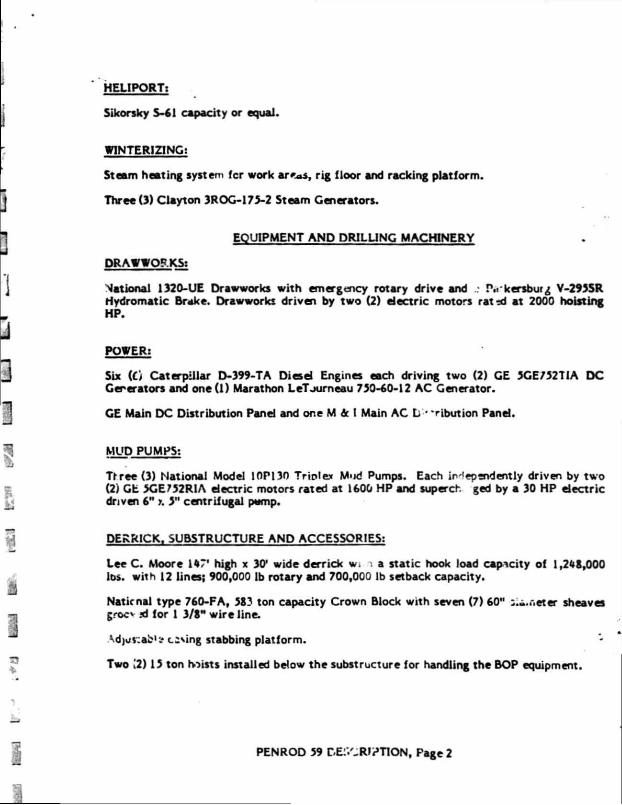
HELIPORT;
Sikorsky S-61 capacity or equal.
WINTERIZING;
Steam heating system fcr work areas, rig floor and racking platform.
Three (3) Clayton 3ROG-175-2 Steam Generators.
EQUIPMENT AND DRILLING MACHINERY
DRAWWORKS;
National 1320-UE Drawworks with emergency rotary drive and P.rkersburg V-295SR Hydromatic Brake. Drawworks driven by two (2) electric motors rat td at 2000 hoisting HP.
POWER:
Six id Caterpillar D-399-TA Diesel Engines each driving two (2) GE 5CE/527IA DC Generators and one (1) Marathon LeTourneau 750-60-12 AC Generator.
GE Main DC Distribution Panel and one M ic I Main AC L - -ribution Panel.
MUD PUMPS;
Trree(3) National Model 10P130 Triplex Mud Pumps. Each independently driven by two (2) GE 5GE752R1A electric motors rated at 1600 HP and superch ged by a 30 HP dearie driven 6" J. 3" centrifugal pump.
DERRICK. SUBSTRUCTURE AND ACCESSORIES;
Lee C . Moore 1ST' high x 30* wide derrick w. a static hook load capacity of 1,248,000 lt>s. with 12 lines; 900,000 lb rotary and 700,000 lb setback capacity.
National type 760-FA, 583 ton capacity Crown Block with seven (7) 60" eter sheaves groc* ni for 1 3/8" wire line.
KdjuSCth1* casing stabbing platform.
Two (2) 15 ton hoists installed below the substructure for handling the BOP equipment.
PENROD 59 DE:/-Rli»TION, Page 2
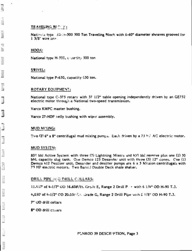
TRAVELING Bl f V r j
Nati 'Wi' j type iw- .1-500 500 Ton Traveling Hlock w i th 6-60" diameter sheaves grooved lor l 3/S r wire nr.*
HOCK-
National type H-5QC, t p t t i t > 500 ton
SWIVEL:
National type P-650, capacity 050 ton.
ROTARY EQUIPMENT;
National type C-375 ro'.arv with 37 1/2" table opening independently driven by an GE752 electr ic motor through a National two-speed transmission. Varco KMPC master bushing.
Varco 27-HDP Kelly bushing wi th wiper assembly.
MUD MIXING;
T v o (2) 6" x 8" centr i fugal mud mixing p u m ^ . Each driven by a 73 Hr AC electr ic motor.
MUD SYSTEM:
800 bbl Active System w i th three (?) Lightning Mixer* «nd 450 bbJ res-rve plus one ( l ) 50 bhl . capacity slug tank. One Demco 123 Desander unit w i th three (3) 12" cones. Cne (1) Demco <»12 Hesilter un i t . Desander and desilter pumps are 6 x 5 Mission centri fugals with 75 HF electric motors. Two BaroiJ Double Deck shale sha'.ei.
DRILL PIPE 'M • Z PRILL C 3LLARS:
I M i r of 4-1/2" OD J 6 .600/ f t . Gr^c- E, Range 2 Dr i l l P • wi th 6 J/4" OD H-90 T.3.
4,030' of <»-l/2" OD 20.00f K*. j r a d e G, Range 2 Dr i l l Pipe wivh C 1/8" OD H-90 T.3.
7" OD dri l l collars
8" OD dr i l l ctMars
P1NROD 59 DESCRIPTION, Page 3

2 - Drilco Kelly 5 1/4" HEX by 2 13/16" bore by 40* long with 4 1/2" I.F. pin.
Handling tools for drill pipe and drill collars.
BLOWOUT PREVENTERS;
One Hydril 2! i , V 'ISP 2000 psi W.P.; One HydrU 13 5/8" GL 5000 psi W.P. Three Cameron 13 5/2 v,?00 psi W.P., type M U " Single; One Cameron 13 5/8" - 10,000 psi W.P., type "U" uouble. One 10,000 psi W.P. choke manifold with adjustable chokes. Preventers and choke manifold treated for H2S.
Blowout preventer control unit is a Payne 160ANS 3000 psi W.P. accumulator system.
COMMUNICATIONS EQUIPMENT;
1 - Harris Single Side Band Model RF230M with 1000 watt linear amplifier. 2 - Sailor VHF Marine Transceiver Model 144 AC. 1 - Southern Avionics Beacon Model SS-1000.
SPECIAL EQUIPMENT;
1. Varco PS-12 Power Slips for 4-1/2" drill pipe.
2. Bear Automatic Driller.
3. Mud-Gas Separator shop made.
4. Geolograph Six (6) Pen Drilling Recorder.
5. Dual mud lines complete vith dua! standpipe and 3" x 60' - 10,000 psi test rotary hoses.
6. Halliaurton HT-400 cement unit driven with recirculating mixer by two (2) EMD D-79 DC electric motors.
7. Varco Model 10 spinning wrench for 4-1/2" O.D. drill pipe.
8. Varco Model 6500 Power Sub.
9. I otco Pit Level & Flow Line Indicator.
10. Two (2) AMF CUNO HRC-200 water distillation units.
11. Two (2) 400 amp welding machines and oxygen-acetylene equipment.
! 2. Halliburton wire line unit with .092 wire line.
: . OMSCO 6 5/8" 15,000 psi test upper kelly valve.
PENROD 59 DESCRIPTION, Page 4
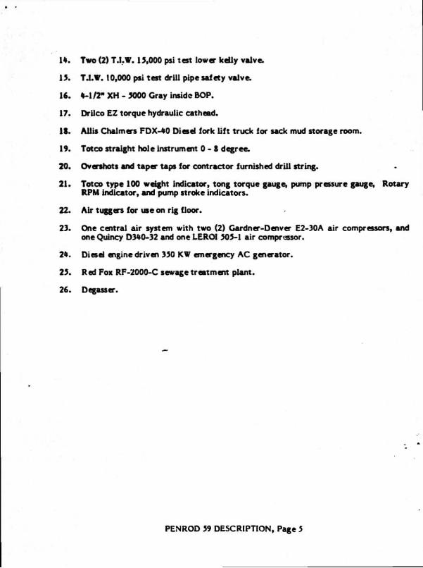
U . Two (2) T.I.W. 15,000 psi t est lower kelly valve.
15. TJ.W. 10,000 psi test drill pipe safety valve.
16. * - l /2- XH - 5000 Cray inside BOP.
17. Drilco EZ torque hydraulic cathead.
IS. Ail is Chalmers FDX-S0 Diesel fork lift truck for sack mud storage room.
19. Totco straight hole instrument 0 - S degree.
20. Overshots and taper taps for contractor furnished drill string.
21. Totco type 100 weight indicator, tong torque gauge, pump pressure gauge, Rotary RPM indicator, and pump stroke indicators.
22. Air tuggers for use on rig floor.
23. One central air system with two (2) Gardner-Denver E2-30A air compressors, and one Quincy D340-32 and one LERC4 505-1 air compressor.
2s. Diesd engine driven 350 KW emergency AC generator.
25. Red Fox RF-2000-C sewage treatment plant.
26. Degasser.
PENROD 59 DESCRIPTION, Page 5
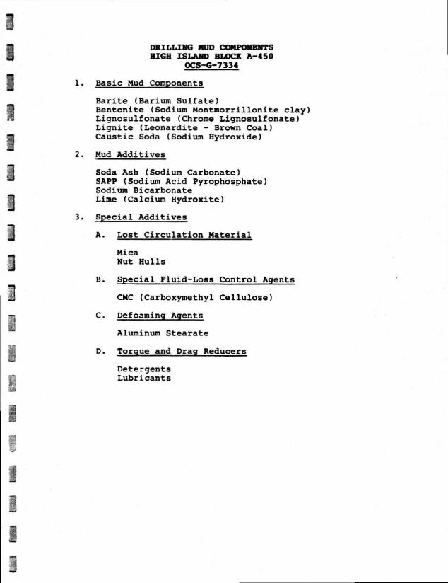
DRILLING MUD COMPONENTS HIGH ISLAND BLOCK A-450
OCS-G-7334
1. Basic Mud Components
Barite (Barium Sulfate) Bentonite (Sodium Montmorrillonite clay) Lignosulfonate (Chrome Lignosulfonate) L i g n i t e (Leonardite - Brown Coal) Caustic Soda (Sodium Hydroxide)
2. Mud Additives
Soda Ash (Sodium Carbonate) SAPP (Sodium Acid Pyrophosphate) Sodium Bicarbonate Lime (Calcium Hydroxite)
3. Special Additives
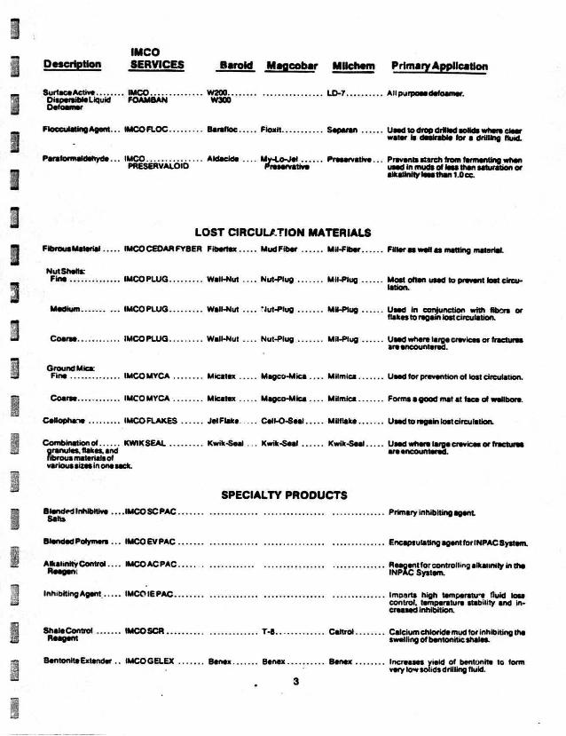
A. Lost C i r c u l a t i o n Material
Mica
Nut Hulls
B. Special Fluid-Loss Control Agents
CMC (Carboxymethyl Cellulose)
C. Defoaming Agents
Aluminum Stearate
D. Torque and Drag Reducers Detergents Lubricants
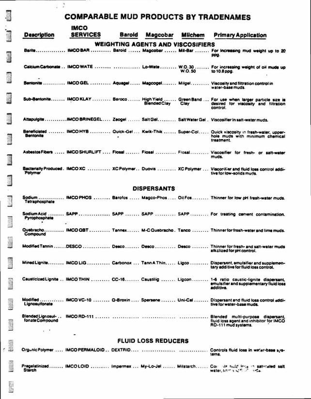
COMPARABLE MUD PRODUCTS BY TRADENAMES IMCO
Description SERVICES Baroid Magcobar Mllchwn Primary Application
WEIGHTING AGENTS AND VISCOSIFIERS Barite IMCO BAR Baroid Magcobar Mil-Bar For increasing mud wtight up to 20
PPO
Calcium Carbonate . . IMCO WATE Lo-Wate W.O.30 For increasing weight of Oii mu f l i up W O 50 to 10.8ppg.
BomonHt IMCOOEL Aquagel Magcogel M.igei Viscosity and filtration control m •A a ler-base muds.
Sub-eentonite IMCO KLAY Baroco High Yield Green Band . . . For u s * when larger pan,cle size is BlenfledClay Clay desired for viscosity snd filtration
control.
Artapulgita IMCOBRINEGFI Zeogel Salt Gel Salt Water Gel . Viscosifier in salt-water muds.
Btnsf idatsd IMCO HYB QUICK-Gel . . K w i k - T h * Super-Col Ouick viscosity in fresh-water, upper-Bsntonits . hols muds with minimum chemical
treatment
Asbestos Fiber, IMCO SH URL IFT Flosal Fiosal Flosal Viscosifisr for fresh- or salt-water muds
Bac.enaiiy Produced. I M C O X C XCPolymsr . . Ouovis XC Pol/mer VisconlUr and fluid loss control addi-Pofymer tivs for low-solid* muds
DISPERSANTS Sodium IMCO PHOS Barofos Magco-Phos . . . . OilFos Thinner for low pH fresh-water muds
Tstrsphosphsts
Sodium Acid SAPP SAPP SAPP SAPP For treating cerient contamination.
Pyrophosphate
Quebracho IMCOQBT Tannex M-C Quebracho. Tanco Thinnerforfrssh-wster snd lime mods Compound
Modified Tsnnin D E S C O Desco Desco Desco Thinner for fresh- snd salt-water muds slkclized for pH control.
MinedLignite I M C O U O Carbonox . . . TannATh in Lig CO Dispersant. emulsifier and supplementary additive for f luid loss control.
Causticized Lignite . . IMCO THIN CC-16 Csustilig Lig con 1 4 ratio caustic-lignite dispersant emulsifier and supplementary fluid loss additive
Modified iMCOVC-10 O-Srosin.... Spereene Um-Cai Dispersant snd fluid loss control m*M-Lignosurfonate tive for wster-base muds
Blended Lignosul- . . IMCORD-111 Blended multi-purpose dispersant fonate Compound fluid loss agent and inhibitor for IMCO
RD-111 mud systems
FLUID LOSS REDUCERS Organic Polymer . . . . IMCO P E R M A L O I D . . DEXTRIO Controls fluid loss in wa'.«r-0sse s,<s-
tsms
Pregelatinlzsd IMCOLOID Impermss . . . My-Lo-Jei Mllstarch Co . .if iwfc1 "-.» s a w - t e d salt
Surch water.i.i"< s:*" -•" • «!•.

IMCO Psacftotfori SERVICES Bsroki Magcobsr MPchom Primary Apc^teaSon
Sodium Cartooxy.... IMCO CMC Cellex MagcoCMC . . . . MaehemCMC . For fluid lot* control and bam* sus-methyfCeHutoee (Regular) (Regular) (Regular) (Med-Vis) pension in water-base mudi.
Sodium Carboxy-.... IMCO CMC Ceilex Maoco-CMC.... MiichemCMC . For fluid toss control and viscosity methyl Cellulose (Hi-Vis) (Hi-V.a) (Hi-Vis) (Hl-Vis) building in low-solids muds.
Polyanionic CeMulosic DRISPAC Dnspac Drispac Driapac Fluid loss control additive and viscosi-Pclymer tier in salt muds
PoiyamcmcCeiiuinsic DRISPAC Driapac Drispac Drispac Primary fluid loss additive secondary Polymer 8UPGRLO Supsrto Suporto Superio viscosifier in water-base.nuds.
Sodium CYPAN Cypan Cypan Cypan Fluid loss control In caaciunvfree tow Pofyacrytato solids and non-dispersed muds
Sodium WL-ioo . . . VYL-100 WL-100 WL-100 Fluid toss control in calctunvfrM tow Poly aery I ate sol ids and non-diapsrssd muds.
LUBRICANTS, DETERGENTS, EMULSIFIERS Extreme Pressure IMCOEP EP Mud Lube . Bit Lube Lu bo-Film . . . . Used in water-base muds to Impart Lubncant LUBE extreme pressure lubricity.
Processed SOLTEX Sons* Sottex Soltex Used In water-base muds to tower Hydrocarbons downhole fluid toes snd mMmizt
heaving shale.
water D.spers. bie ... IMCO STABIL- IT I-WD Lubricant and fluid ton reducer for Asphalts HOLECOAT HOLE water-base muds that contam no d.esel
or crude oii.
Oil Disperses IMCO Baroid Pave-A-Hoto Carbo-Seal— Lubricant and fluid toss reducer tor Asphalts MUD OIL Asphalt water-base fluids that contain diesel
or crude o i .
Oil Soluble IMCO Skot-Free . . . Pipe Lax Petrocote Non-weighted fluid for spotting to free Surfactants FREEPIPE differentially stuck pipe
Detergent IMCOMD Con Det D-O Mitohc.nMO... Used in water-base muds to aid In dropping sand. Emulsifies oil. reduces torque snd minimizes bit-bailing.
Non-Ionic Emulsifier. DME Aktafto-E . . . . SurFak-E DME Emulsifier for surfactant muds
Blend of Anionic IMCO SWS Tr.mulsc . . . . Saimex v Atlosol* Emulsifier for salt- and frssh-wator Surfactants AtlosoiS muds.
An Organic Entity IMCC TorqTr.m .. . DOS-3 Mi'-Pi«te2 . . . . Supplies the hrbheating properties Of Neutralized with LUBRIKLEEN oils without environmental pollution.
Bier d ol Fatty Acids IMCO SPOT SF 100 Invert emulsion that may be weighted Sulfonates. A to desired density for spotting -to free Asphettic Materials differentially stuck pipe.
DEFOAMERS, FLOCCULANTS. BACTERICIDES Aluminum Aluminum Aluminum... Aluminum Aluminum Defoamer for lignosulfonate muds Stearate Stearate Stearate Stearata Stearate
Sodium Alkyl Aryl. . . . IMCODEFOAM Magco nol Defoamer for salt saturated muds Sulfonate Defoamer
IMCO Description SERVICES Baroid Mageobar Mllchwn Primary Application
Surface Active IMCO W200 LO-7 Al l purpoea defoamer. Dispenib le Liquid FOAM BAN W300 Defoamer
Flocculating Agent . . . IMCOFLOC Barafloc Floxit S a p v M Used to drop drilled solid* where -leer water i t desirable for a drilling. I W .
Paraformaldehyde.. . IMCO Aldacide . . . . My-Lo-Jei Preservat ive.. . Prevents stsrch from fermenting when PRESERVALOID Preservative used in muds of less than saturation or
alkalinity less than I .Occ
LOST CIRCULATION MATERIALS Fibrous Material IMCO CEDAR FYBER Fibertex Mud Fiber M.l-Fiber Filler as well as matting material.
NutShetts: P«»e IMCOPLUQ Wall-Nut . . . . Nut-Plug Mil-Plug Most often used to prevent lost circu
lation.
Medium IMCO PLUG Wall-Nut . . . . "Jut-Plug Mil-Plug Ueed in conjunction with fibers o r flakes to regain lost circulation.
Coarse IMCOPLUQ Wall-Nut . . . . Nut-Plug Mil-Plug Used where large crevices or fractures sre encountered.
Ground Mica:
Fine IMCOMYCA Micatex Magco-Mica . . . . MHmica Used for prevention of lost circulation.
Coarse IMCOMYCA Micatex M a g c o - M i c a . . . . MHmica Forms a good mat at face of wellbore
Cellophane IMCO FLAKES Jel Flake Cell-O-Seal Milf iake Used to regain lost circulation.
Combinat ion of KWIK SEAL Kwik-SeaJ . . . Kwik-Seal Kwik-Seal Used where large crevices or fractures granules, flakes, and are encountered, f ibrous materials of various sizes in one sack.
SPECIALTY PRODUCTS
Blendrd Inhibttive . . . .IMCO SC PAC Primary inhibiting agent
Salts
Blended Polymers . . . IMCO EV PAC Encapsulating agent for INPAC System.
Alkal ini ty C o n t r o l . . . . IMCO AC PAC Reagent for control l ing alkalinity in the
neageni INPAC System. Inhibit ing Agent. IMCO IE PAC Imoarts high temperatu-e f luid loss
conlrol. temperature stability and increased inhib i t ion
She le Control IMCO SCR T - t Caltrol Calcium chloride mud for inhibiting the Reagent swell ing of bentonit ic shales
Bentonite Extender . . IMCOGELEX Benex Benex Benex Increases yield of bentonite to form very low sohds dril l ing fluid.
3

IMCO Descry,- - SERVICES Baroid Magcobar Mllchtm Primary Application
FKmMgWkmine IMCOPT-1Q2 Coat-ClS15 - Magco Inhibitor. Ami-Tex Corrosion inhibitor Coat-415 No 6
Specioliy Blended . . . IMC08ULF-X Mil-Guard For use as a hydrogen sulfide scaveri-ZincComoounda gar In water-basemud*.
Synergistic IMCO POLY Rx Resinex Rheological etaMlization and filtmtio.i Polymer 8 lend control.
Liquid Corrott'--- I vt CO CRACK CHEK Prevent stress-cracking ol drill swings Inhibitor in an H,S environment
COMMERCIAL CHEMICALS Sodium Sodium Sodium Sodium Sodium Ueed in water-base muds to prevent
Chromate Chromate Chromate Chromate Chromate high temperature gelation.
Sodium Hydroxide... Caustic Soda Caustic Sods . Caustic Sods . . . Caustic Soda For pH control in water-base muds.
Sodium Carbonate... Soda Ash Soda Ash — Soda Ash Soda Ash For treating out calcium sulfate in low pH muds.
Sodium8icarbonvie Sodium Sodium Sodium For treating out calcium sulfate or Bicarbonate Bicarbonate Bicarbonate cement in high pH muds
BariumCtrbona-- Anhydiox . . . Barium Barium For treating out calcium sulfate (pH >.an>w. .e Carbonate Carbonate should be above 10 for best results)
Calcium Sulfate Gypsum Gypsum Gypsum Gypsum Source of calcium for formulating gyp muds
Calcium Hydroxide .. Lime Lime Lime Lime Source ot calcium for formulating lime muds.
Sodium Chloride . . . . Salt Salt Salt Sail For saturated aalt muds and resistivity control.
Chrome Alum Chrome Alum Chrome Alum Chrome Alum . . . Chrome Alum . For use in cross-linking XC P.«»ymer (chromic chloride) systems.
OIL BASE AND INVERT EMULSION SYSTEMS
invert Emulsion IMCOKENOL-S invermul . . . . VortoN Carbo-Tec . . . . Dmimg fluids used where extremely System and high temperatures sre encountered.
IMCO KEN-X also a drilling, completion, or workover fluid applicable where only o i contact with formations is desired.
, -Oil Base Mud IMCO KEN-SUPREME Oilfaze For drilling wster sensitive formations.
OIL MUD ADDITIVr .
' Primary Emulsifier... IMCOKENO'.-S . vertoil Carbo-Tec(D) Primary additives to form stable wster-snd snd in-oil emulsion.
IMCO KEN-X Cr Carbo-Tec(L)
^ Viscosifier and IMCO KEN G t 59 Carbo-Gel . . . . Provides viscosity, -veight suspension. i Gelling Agent snd snd filtration control.
IMCO KEN-X Ci
i High Temperature . . . IMCO KEN-X. . . . . . . OuratontHT. DV-22 and Improves emuHion under high temper-_J Stabilizer Cone. S3 OV-33 atureconditions
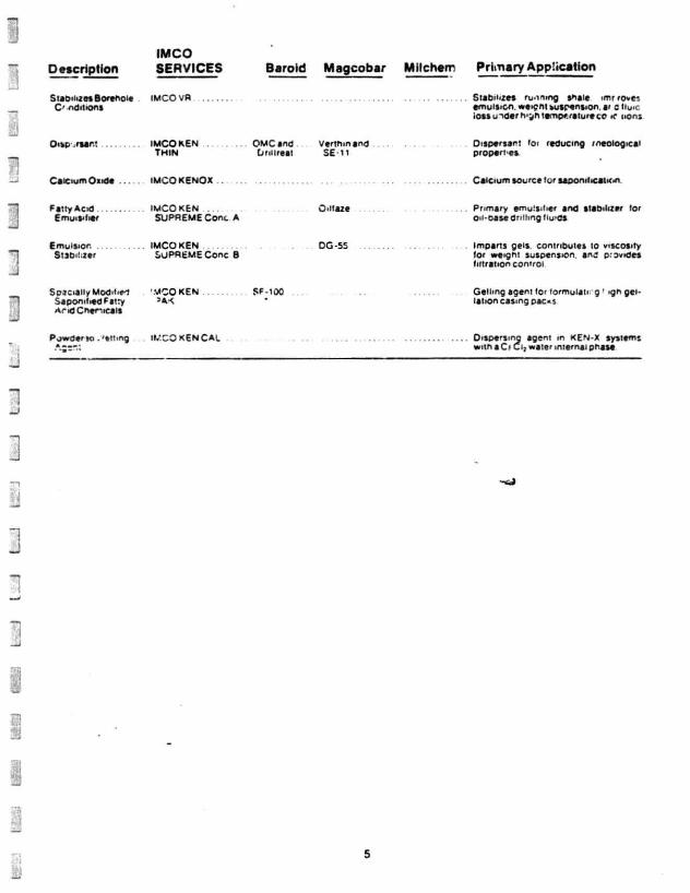
IMCO Description SERVICES Baroid Magcobar Mllchom Primary Application
Stabilizes Borehole C" e d i t i o n s
IMCOVR S u b l i n e s running stale imr roves emulsion. <*e>cnt suspension, ar e Hu<c i ossu^e rh ' j n t emor . r a t u reco * nana
Oisp .rear; IMCO KEN THIN
OMC and (jni ireat
Verthm and . . . . . . Dispersant io> reducing rneologicai SE-11 proper res
Calcium Oside IMCOKENOX Calcium source lor saponification
Fatty ACK) E m u i S ' l i e r
IMCO KEN . . . SUPREME Cone A
Oiiiaze Pnmary emu!sii>er and stabilizer lor o ca se dri l l ing tiu'dS
Emulsion Stabilizer
IMCO KEN SUPREME Cone B
DG-SS Imparts gels, contributes to viscosity lor weight suspension, ana provides fi ltration control
S o c i a l l y Mod i l iM Saponified Fatty AndChernca is
'•VCO KEN ' A <
SF-100 Gelling agent for lormulati g ' <gh gei-Iation casmg pac«s
Powder to . 'et tmg IMCO KEN CAL Dispersing agent m KEN-X systems with a C* water internal phase
5
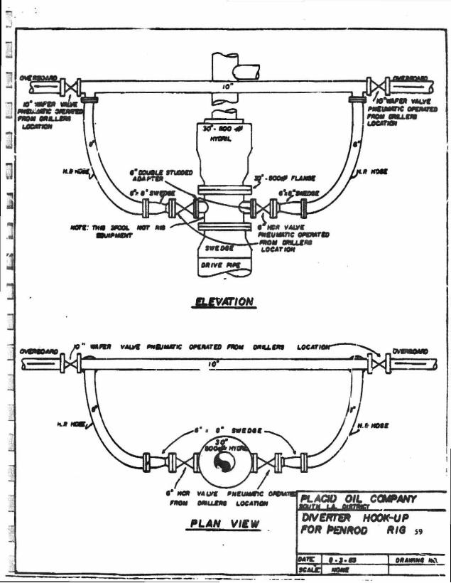
ELEVATION
•" MC* wui Pmtummc nom omul** LOCATION
PLAN VIEW
PL AOU OIL CCNPANY
DtVERTEP HOOK-UP FOR PENPOG PIQ 59
CONTINGENCY PLAN HIGH ISLAND BLOCK A-450
OCS-G-7334
Placid O i l Company maintains at i t s own expense various
types of equipment t o deal with o i l s p i l l s . Included are
boc-.s, large and sma..l vessels, skimmers and the l i k e . Placid
f i l e d a revised O i l S p i l l Contingency Plan February 28,
1985, which was approved March 8, 1985. A d d i t i o n a l l y ,
they are a member of Clean Gulf Associates f o r Areas I ,
I I , and I I I . I n the event that a s p i l l occurs, even thouyn
i t may not have originatec 3 with a Placid operation or f a c i l i t y ,
an a l e r t procedure i s immed a t e l y i n s t i t u t e d . Immediate
n o t i f i c a t i o n i s made to the O i l Discharge Response Coordinator
i n Houma and to the appropriate Feieral and State Agencies.
At the same time e f f o r t s are begun to stop and contain
the s p i l l and to assess what, i f any, equipment w i l l be
needed.
I f the s p i l l i s too large f o r the on-site personnel
to c o n t r o l , company equipment, f a c i l i t i e s , and personnel
w i l l be immediately marshalled and, i f needed. Clean Gulf
Associates w i l l be c a l l e d i n . Placid bases at Houma, I n t e r -
coastal C i t y , and Cameron, and Corpus C h r i s t i are on a
continual standby basis with appropriate concingcncy responses
assigned to them. Clean Gulf Associates has i t s main base
at Grand I s l e . In the Texas area. Clean Gulf maintains
equipment
t-XHIBIT V I I
at bases i n Galveston (Texas Cit y ) and Rockport (Fulton).
The project araa i s 72 miles by boat from Galveston, TX
or 9 hours t r a v e l i n g time and 115 miles by boat from Cameron,
LA or 13 hours t r a v e l i n g time and 160 miles by boat from
Ingleside, TX or 18 hours t r a v e l i n g time.
A l l procedures, personnel, and equipment are designed
t o be i n compliance w i t h OCS Order No. 7 ( P o l l u t i o n and
Waste Control).

POTENTIAL GEOLOGIC HAZARDS SURVEY AND
CULTURAL RESOURCES REPORT
HIGH ISLAND AREA. BLOCK A450 OCS NO. G-7334
Prepared for: TEXACO INC.
1501 CANAL ST. NEW ORLEANS, LA 70160
Prepared by: INTERSEA RESEARCH
9940-A BARNES CANYON ROAD SAN DIEGO, CA 92121
OF
4 JANUARY 1985
INTERSEA RESEARCH
1.0 DtfTRODUCTION
Intersea Research conducted a mult:sensor high resolution
geophysical survey «if the High Island Area, Block A450 aboard the M/V
MI TGHT STAR f era December 12 tnrough December 17, 1984. The survey
area is located approximately 72 miles southeast ot Galveston, Texas
L the i u l f of Mexico (Figure 1) . The purpose of the survey conducted
for tvaPOf 'inc. was to investigate and evaluate potential geologic
hazarr-s v i.'c'i might affect sea floor installations and/or shallow
dr i l l i ng operations within this Federal Lease Block, and to identify
ifsstt structures, and objects of cultural significance that might be
i- vscirt and require preservation measures. Federal guidelines
r.-i-xilated in 30 CFR 250.34 (A) Exploratory D r i l l i n g Plan, and
M.K.:?. Gulf of Mexico Area Notice to Lessees 83-3 were followed during
survey and report ef for ts .
FatNmeter, subbottom prof i le r , mini-sparker, water gun, magneto
meter and side scan sonar were operated continuously during the
survey. Na/igation f ixes were registered simultaneously on a l l
gecphysicaJ records at a 150 m interval c-iong survey lines. Approxi
mately 111' line kilometers of data recorded include 17 north-scurh
dip lines spaced 300 m apart and 6 east-west t ie lines spaced 900 m
apart. ^ersea Research processed the navigation data and plotted
a l l li^es at a scale of 1:12,000 (1"=1000'). This plot was then used
as a bese map for a l l geophysical data ^ f l o t a t i o n s . This report
describes the instrumentation and inethodolcry used in the acquisition
and interpretation of data, and presents the results and recommenda
tions which are pertinent to shallow d r i l l i n g and associated opera
tions
INTERSEA RESEARCH
1

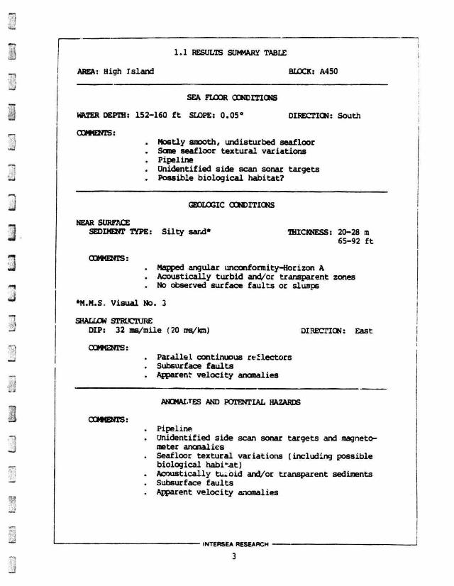
1.1 RESULTS SUMMARY TABLE
AREA: High Island BLOCK: A450
SEA FLOOR CONDITIONS
WATER DEPTH: 152-160 f t SLOPE: 0.05° DIRECTION: South
COMMENTS: . Mostly smooth, undisturbed seafloor . Some seafloor t ex tu ra l variations . Pipeline . Unidentif ied side scan sonar targets . Possible b io log ica l habitat?
GEOLOGIC CONDITIONS
NEAR SURFACE SEDIMENT TYPE: S i l t y sand* THICKNESS: 20-28 ra
65-92 f t
COMMENTS: . Mapped angular unconformity-Horizon A . Acoustically t u rb id and/or transparent zones . No observed surface f au l t s or slumps
*M.M.S. Visual No. 3
SHALLOW STRUCTURE DIP: 32 ms/mile (20 ms/km) DIRECTION: East
crjfCNsst . Paral lel continuous ref lec tors . Subsurface f a u l t s
Apparent ve loc i ty anomalies
ANOMALTES AND POTENTIAL HAZARDS
COMMENTS: . Pipeline . Unidentified side scan sonar targets and magneto
meter anomalies . Seafloor tex tura l variat ions (including possible
biological habi tat) . Acoustically tu -o id and/or transparent sediments . Subsurface f a u l t s
Apparent ve loc i ty anomalies
INTERSEA RESEARCH
2.0 INTERPRETATION PROCEDURES AND RESULTS DISCUSSION
Intersea Research performed the interpretation of a l l geophysical
recordings (see Appendix B for survey and report personnel). The data
are of good quality and permit the detection and evaluation of
potential geologic hazards within the survey area. Copies of repre
sentative records from several geophysical systans are presented in
this section to i l lustrate the data quality in this area. Overlays
provide an example of the interpretation performed by Intersea.
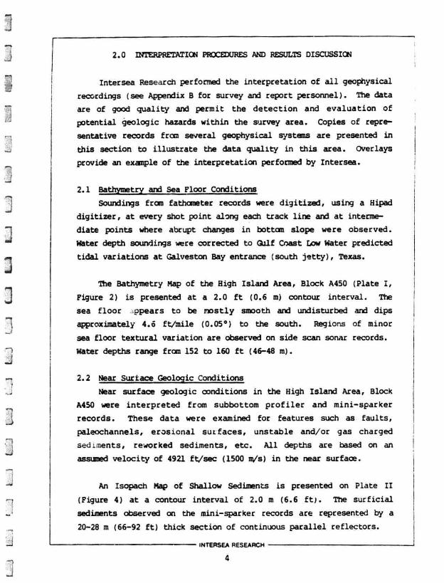
2.1 Bathymetry and Sea Floor Conditions
Soundings froro fathometer records were digitized, using a Hipad
digitizer, at every shot point along each track line and at interme
diate points where abrupt changes in bottom slope were observed.
Water depth soundings were corrected to Gulf Coast Low Water predicted
tidal variations at Galveston Bay entrance (south j e t t y ) , Texas.
The Bathymetry Nap of the High Island Area, Block A450 (Plate I ,
Figure 2) is presented at a 2.0 f t (0.6 m) contour interval. The
sea f loor ppears to be mostly smooth and undisturbed and dips
approximately 4.6 ft /mile (0.05°) to the south. Regions of minor
sea floor textural variation are observed on side scan sonar records.
Water depths range from 152 to 160 f t (46-48 m).
2.2 Near Surface Geologic Conditions
Near surface geologic conditions in the High Island Area, Block
A450 were interpreted from subbottom p r o f i l e r and mini-sparker
records. These data were examined for features such as faults,
paleochannels, erosional surfaces, unstable and/or gas charged
sediments, reworked sediments, etc. A l l depths are based on an
assumed velocity of 4921 ft/sec (1500 m/s) in the near surface.
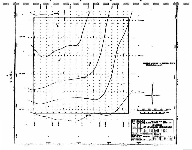
An Isopach Map of Shallow Sediments is presented on Plate I I
(Figure 4) at a contour interval of 2.0 m (6.6 f t ) . The surf ic ia l
sediments observed on the mini-sparker records are represented by a
20-28 m (66-92 f t ) thick section of continuous parallel reflectors.
INTERSEA RESEARCH

The mapped isopach horizon (Horizon A) represents an angular unconformity in the near surface (see Figures 3 and 5). This surface represents an erosional period which probably occurred during the last subaerial exposure of this region 17,000-23,000 years b.p. ( C . E . I . , sea level curve, 1977). Reflectors above Horizon A are parallel to the sea floor and dip approximately 4.6 ft/mile (0.05°) to the south. This sequence probably represents interbedded sands and silty sands deposited while sea level underwent mild fluctuations (C.E.I, sea level curve, 1977). Surficial sediments are silty sands (M.M.S. Visual No. 3). Sediments below Horizon A dip approximately 70 ft/mile (0.75s) to the south suggesting deposition during a slow gulfward migration of the land/sea interface.
Acoustically turbid and/or transparent zones are observed on the subbottom profiler and mini-sparker records (see Figures 3 and 5). These areas may represent sediments reworked by biological or bottom current processes or they may be gas charged sediments. High amplitude reflections are seen at the top of some of these regions.
No evidence of paleochanneling, surface faulting, or sediment slumping is observed in the near surface data.
2.3 Shallow Structure A single continuous reflector (Horizon B) is used to depict the
shallow structure in the survey area (Figure 7). Two-way reflection times from time zero, (assumed sea surface) to Horizon B are plotted and contoured at a 10 ms interval on Plate I I I (Figure 7). Horizon B dips approximately 32 ms/mile (20 ms/km) to the east and is located between 455 and 525 ms below the sea surface. Reflectors above and below Horizon B are parallel and continuous suggesting continuous deposition in a stable environment.
Three normal subsurface faults are observed on the near trace data. These faults trend generally east-west cr northwest-southeast and are down-dropped 5-10 ms to the south (Figure 6).
INTERSEA RESEARCH
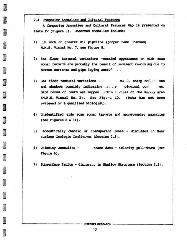
2.4 Composite Anomalies and Cultural Features A Composite Anomalies and Cultural Features Map is presented on
Plate IV (Figure 8). Observed anomalies include:
1) 10 inch or greater oil pipeline (proper name unknown) M.M.S. Visual Mo. 7, see Figure 9.
2) Sea floor textural variations -mottled appearance on side scan sonar records are probably the result o.' sediment reworking due to bottom currents and pipe laying activ' . .
3) Sea floor textural variations - s sr.v.l, sharp teih" 'ons and shadows possibly indicating ological COT- CS. Bard banks or reefs are mapped . jthin & •oiles of the survey area (M.M.S. Visual No. 3). See Figi c* 10. (Data has not been reviewed by a qualified biologist).
4) Unidentified side scan sonar targets and magnetometer anomalies (see Figures 8 & 11).
5) Acoustically chaotic or transparent zones - discussed in Near Surface Geologic Conditions (Section 2.2).
6) Velocity anomalies < trace data - velocity pull-downs (see Figure 6).
7) Subsurface Faults - dierust^u in Shallow Structure (Section 2.3).
INTERSEA RESEARCH
12
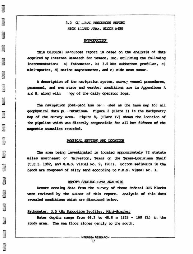
3.0 CU..-JHAL RESOURCES REPORT HIGH ISLAND AREA, BLOCK A450
INTPOOOCTIOr
This Cultural R*»°ources report is based on the analysis of data acquired by Intersea Research for Texaco, Inc. utilizing the following instrumentstion: a) fathometer, b) 3.5 kHz subbottom profiler, c) mini-sparker, d) marine magnetometer, and e) side scan sonar.
A description of the navigation system, survey vessel procedures, personnel, and sea state and weather conditions are in Appendices A a,d B, along with ipy of the daily operator logs.
The navigation post-plot has be ised as the base map for a l l geophysical data pL stations. Figure 2 (Plate I) is the Bathymetry Nap of che survey area. Figure 8, (Plate IV) shows the location of the pipeline which was directly responsible for a l l but fifteen of the magnetic anomalies recorded.
PHYSICAL SETTING AND LOCATION
The area being investigated is located approximately 72 statute miles southeast o~ la Ives ton, Texas on the Texas-Louisiana Shelf (C.E.I . 1982, and M.M.S. Visual No. 9, 1983). Bottom sediments in the block are conposeri of silty sand according to M.M.S. Visual Nc. 3.
REMOTE SENSING DATA ANALYSIS Remote sensing data from the survey of these Federal OCS blocks
were reviewed by the author of this report. Analysis of this data revealed conditions which are discussed below.
Fathometer, 3.5 kHz Subbottom Profiler, Mini-Sparker
Water depths range from 46.3 to 48.8 m (152 - 160 ft) in the study area. The sea floor slopes gently to the south.
INTERSEA RESEARCH
17

Penetration of the bottom sediments by the subbottom profiler
resolves approximately the upper 30 m (98 f t ) .
Magnetometer and Side Scan Sonar
A Geometries Model proton precession marine magnetometer was
operated on a l l survey lines. The sensor was 143.4 m (470 f t )
behind the navigation antenna. Receiver depth was 25.9 m (84.9 f t ) .
System sensitivity was one gamma and the sampling interval was
2/12.5 m (41 f t ) . Noise level was approximately + 1.0 gamma. The
scale was set at 2 gammas per division.
Thirty-one (31) magnetic anomalies were recorded during the
survey. Sixt'.en (16) anomalies ^represent the pipeline which transects
the block. The remaining correspond with material related to the
mart-made structures (pipeline, platform dril lholes), and a fairway
located near Block A450 (see Table 1).
The 100 kHz E.G.t G., SMS 960 Side Scan Sonar System was used
over the survey area. The sonar f ish was towed behind the research
vessel at approximately 10-20 m (33-66 f t ) above the sea floor. The
distance from sensor to navigation antenna was approximately 50 m (164
f t ) . The sonar was operated at a sweep rate of 200 m/channel, with
25 meters between ranging markers. Resolution was approximately 1 m
(3.3 f t ) .
Seventy-nine (79) side scan targets were noted in these c.ta.
Forty-six (46) targets arc plotted on the Cultural Features and
Anomalies Map (Plate IV). See Table I for an explanation ' i the
difference in number of targets listed and those illustrated c*> .: iate
rv (Figure 8) .
Analysis of side scan sonar data for High Island, Block A45C also
revealed a significant ai»unt of sea floor textural variations in
several apparent forms. T.iese variations are discussed in more detail
in the geophysical section oi this report.
INTERSEA RESEARCH
18

Additionally, -he sea floor changes are illustrated on the Cultural
Features and Anomalies Map (Plate IV) and summarized as follows:
A. ) Probable pipeline dredge spoils
B. ) Possible biological conmunities
C. ) Probable sand waves or reworked sediments
ARCBAECLQGICAL ASSESSMENT AMD REVIEW OF EXISTING LITERATURE
The MMS has determined Historic and Prehistoric Cultural
Resources high probability areas * the Gulf of Mexico. The curr :nt
study aree High Island, Block A450 lies within the MMS high probabi
l i t y zone for prehistoric cultural resources (MMS Visual No. 11).
Prehistoric
Literature Review and Data Analysis
According to the revised sea level curves published by Coastal
Environments, Inc. (1982) for the northern Gulf of Mexico, a gradual
rise of sea level took place 12,000 to 8,500 years B. P.. Associated
development of extensive coastal wetlands (swamps and marshes) took
place. In this environment. Pleistocene megafauna flourished, and
abundant evidence of human act ivi ty throughout the area, particularly
during the closing interval remains today.
A broad-scale interpretation of the re l ic t tocography of the
Gulf, including the East Texas Shelf, was made by C.E.I. (1978).
Their maps and profiles show re* let shelf features of the region. The
project v ic in i ty appears to l i e approximately 6 miles west of the
Claypile Bank area which is situated on the East Texas Shelf (See
Figure 1).
No paleochannels or other re l i c t georaorphic features of potential
archaeological significance were detected in the geophysical data
collected from High Island A450. There are some areas in the near
surface which appear transparent on the subbottom profiler records.
These regions are interpreted as sediments reworked by bottom current
actions.
INTERSEA RESEARCH
19
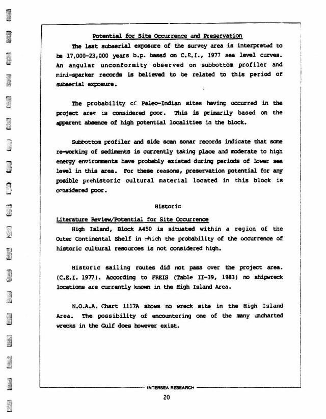
Potential for Site Occurrence and Preservation The last subaerial exposure of the survey area is interpreted to
be 17,000-23,000 years b.p. based on C . E . I . , 1977 sea level curves. An angular unconformity observed on subbottom profiler and mini-sparker records is believed to be related to this period of subaerial exposure.
The probability of Paiec—Indian sites having occurred in the project are* is considered poor. This is primarily based on the apparent absence of high potential localities in the block.
Subbottom profiler and side scan sonar records indicate that some re-working of sediments is currently taking place and moderate to high energy environments have probably existed during periods of lower sea level in this area. Por these reasons, preservation potential for airy posible prehistoric cultural material located in this block is considered poor.
Historic
Literature Review/Potential for Site Occurrence
High Island, Block A450 is situated within a region of the
Outer Continental Shelf in yhich the probability of the occurrence of
historic cultural resources is not considered high.
Historic sailing routes did not pass over the project area.
(C.E.I. 1977). According to FREIS (Table 11-39, 1983) no shipwreck
locations are currently known in the High Island Area.
N.O.A.A. Chart 1117A shows no wreck site in the High Island
Area. The possibility of encountering one of the many uncharted
wrecks in the Gulf does however exist.
INTERSEA RESEARCH
20
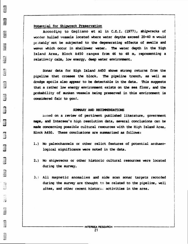
Potential for Shipwreck Preservation
According to Gagliano et al in C.E.I. (1977), shipwrecks of
wooden hulled vessels located where water depths exceed 20-40 m would
pr meanly not be subjected to the degenerating effects of swells and
waves which occur in shallower water. The water depth in the High
Island Area, Block A450 ranges from 46 to 48 m, representing a
relatively calm, low energy, deep water environment.
Sonar data for High Island A450 shows strong returns from the
pipeline that crosses the block. The pipeline trench, as well as
dredge spoils also appear to be detectable in the data. This suggests
that a rather low energy environment exists on the sea floor, and the
probability of sunken vessels being preserved in this environment is
considered fair to good.
SUMMARY AND RECOMMENDATIONS
oaued on a review of pertinent published literature, government
maps, and Intersea's high resolution data, several conclusions can be
made concerning possible cultural resources with the High Island Area,
Block A4S0. These conclusions are summarized as follows:
1. ) No paleochannels or other relict features of potential archaeo
logical significance were noted in the data.
2. ) No shipwrecks or other historic cultural resources were located
during the survey.
3. ) All magnetic anomalies and side scan sonar targets recorded
during the survey are thought to be related to the pipeline, well
sites, and other recent historic activities in the area.
INTERSEA RESEARCH 21
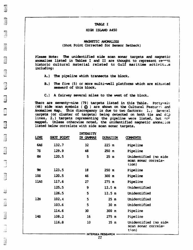
TABLE I
HIGH ISLAND A450
MAGNETIC ANOMALIES (Shot Point Corrected for Sensor Setback)
Please Note: The unidentified side scan sonar targets and magnetic anomalies l isted in Tables I and I I are thought to represent re^-it historic cu l tu ra l material related to Gulf maritime a c t i v i t i e s including:
A. ) The pipeline which transects the block.
B. ) The f ive (5) or more multi-well platforms which are situated seaward of this block.
C. ) A fairway several miles to the west of the block.
There are seventy-nine (79) targets listed in this Table. Forty-six (46) side scan symbols ( 0 ) are shown on the Cultural Pea t u m and Anomalies Map. This discrepancy is due to two factors: 1 . ; Several targets (or cluster of targets) being detected on both t ie and dip l ines, 2.) targets representing the pipeline were l is ted, but not-mapped. Unless otherwise noted, the unidentified magnetic anorra. .os listed below correlate with side scan sonar targets.
LINE SHOT POINT INTENSITY IN GAMMAS DURATION COMMENTS
6AS 132.7 32 225 m Pipeline
7S 129.9 48 250 m Pipeline
8N 120.5 5 25 ra Unident i f ied (no side scan sonar corre lat ion)
9N 123.5 18 250 m Pipeline
IOS 120.5 46 300 m Pipeline
11AS 117.6 27 275 m Pipeline
125.5 9 12.5 m Unidentif ied
126.5 5 12.5 m Unidentif ied
12N 102.4 5 25 m Unident if ied
103.6 5 30 m Unidentif ied
114.6 30 300 m Pipeline
14S 108.2 16 275 ra Pipeline
116.8 10 35 m Unident if ied (no side scan sonar correlat ion)
INTERSEA RESEARCH
22
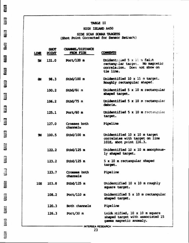
TABLE I I HIGH ISLAND A450
SIDE SCAN SONAR TARGETS (Shot Point Corrected for Senior Setback)
290T LINE POINT
CHANNEL/DISTANCE PROM PISH
SN 131.0 Port/120 a
8N 98.3
100.2
106.2
125.1
127.0
9N 100.5
122.2
123.2
123.7
10S 103.8
108.2
120.3
126.3
Stbd/100 m
Stbd/60 ra
Sthd/75 m
Port/60 m
Crosses both channels
Stbd/100 m
Stbd/125 ra
Stbd/125 ra
Crosses both channels
Stbd/125 B
Port/110 B
Both channels
Port/30 m
COMMENTS
Onidantj :ied 5 x i ra fai:it rectanu}'ilar target. No magnetic correlation. Does not show on tie line.
Unidentified 10 x 15 ra target. Roughly rectangular shaped.
Unidentified 5 x 10 m rectangular shaped target.
Unidentified 5 x 10 ra rectangular debris.
Unidentified 5 x 10 m rectanguJai target.
Pipeline
Unidentified 10 x 10 ra target correlates with target on line 101E, shot point 116.3.
Unidentified 10 x 10 m amorphously shaped target.
5 x 10 m rectangular shaped target.
Pipeline
Unidentified 10 x 10 m roughly square target.
Unidentified 5 x 10 ro rectangular shaped target.
Pipeline
Lnidt itified, 10 x 10 m square shaped target with associated 15 gamma magnetic anomaly.
INTERSEA RESEARCH 23
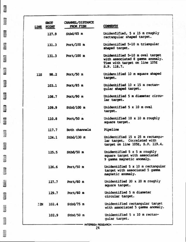
SHOT LINE POINT
127.9
131.3
131.3
11S 98.2
103.1
108.7
109.9
110.8
117.7
124.1
127.7
129.7
!2N 102.4
102.9
CHANNEL/DISTANCE FROM FISH
Stbd/65 m
Port/100 m
Port/100 m
Port/50 m
Port/85 m
Port/90 m
Stbd/100 m
Port/50 m
Both channels
Stbd/130 m
125.5 Stbd/50 m
126.6 Port/50 m
Port/60 m
Port/60 in
Stbd/75 m
Stbd/50 ra
COMMENTS
Unidentified, 5 x 15 m roughly rectangular shaped target.
Unidentified 5-10 m triangular shaped target.
Unidentified 5-10 n oval target with associated 8 gamma anomaly. Ties with target on line 105E S.P. 118.7.
Unidentified 10 m square shaped target.
Unidentified 10 x 15 m rectangular shaped target.
Unidentified 5 m diameter circular target.
Unidentified 5 x 10 m oval target.
Unidentified 10 x 10 m roughly square target.
Pipeline
Unidentified 15 x 25 m rectangular target. Correlated with target on line 105E, S.P. 119.4.
Unidentified 5 x 5 m roughly square target with associated 9 gamma magnetic anomaly.
Unidentified 5 x 10 m rectangular target with associated 5 gamma magnetic anomaly.
Unidentified 20 x 20 m roughly square target.
Unidentified 5 m diameter circular target.
Unidentified rectangular target with associated 5 gamma anomaly.
Unidentified 5 x 10 m rectangular target.
INTERSEA RESEARCH 24
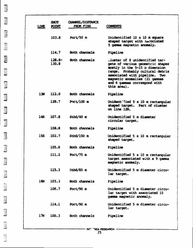
SHOT CHANNEL/DISTANCE LINE POINT FROM FISH COMMENTS
103.8
114.7
14S 107.$
115.3
114.1
Port/50 m
Both channels
128.6- Both channels 130.8
13N 112.0 Both channels
129.7 Port/100 a
Stbd/40 •
108.8 Both channels
15S 102.7 Stbd/150 ra
105.8 Both channels
111.2 Port/75 m
Stbd/85 in
16N 103.3 Both channels
108.7 Port/90 m
Port/90 m
Unidentified 10 x 10 n square shaped target with 2aCOciated 5 gaana magnetic anomaly.
Pipeline
cluster of 8 unidentified targets of various geometric shapes mostly in the 5-15 rn dimension range. Probably cultural debris associated with pipeline. Two magnetic anomalies (21 gammas and 6 gammas correspond with this area).
Pipeline
Unident-cied 5 x 10 m rectangular shaped target. Part of cluster on line 12N.
Unidentified 5 n diameter circular target.
Pipeline
Unidentified 5 x 10 n rectangular shaped target.
Pipeline
Unidentified 5 x 10 n rectangular target associated with a 9 gamma magnetic anomaly.
Unidentified 5 m diameter circular target.
Pipeline
Unidentified 5 m diameter circular target with associated 15 gamma magnetic anomaly.
Unidentified 5 m diameter circular target.
17N 100.3 Both channels Pipeline
INT" 'SEA RESEARCH
25
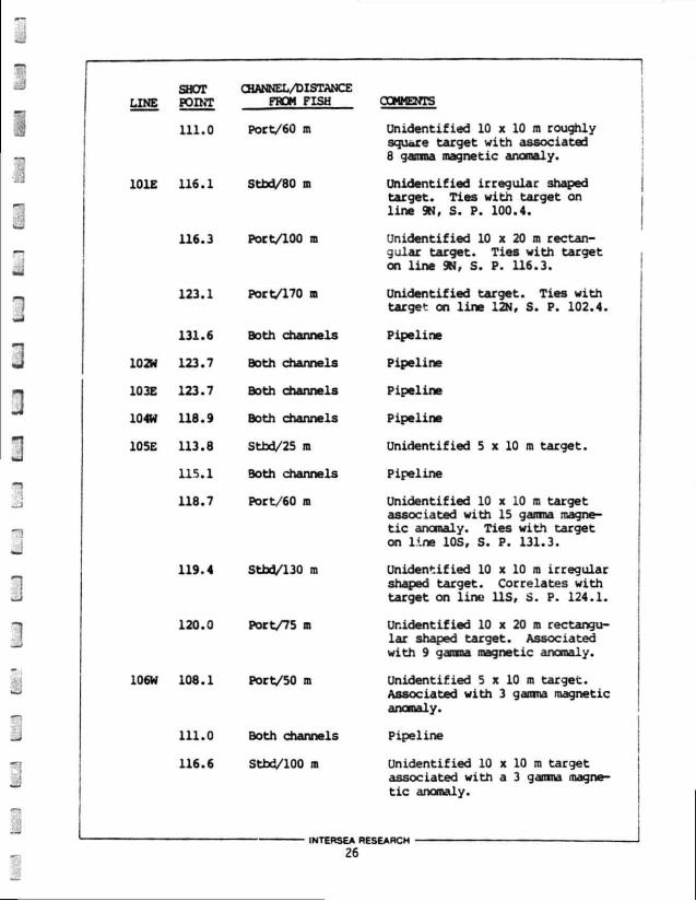
SHOT CHANNEL/DISTANCE LINE POINT FROM FISH COMMENTS
111.0 Port/60 m Unidentif ied 10 x 10 ra roughly square target with associated 8 gamma magnetic anomaly.
101E 116.1 Stbd/80 m Unidentif ied irregular shaped target . Ties wi th target on l ine 9N, S. P. 100.4.
116.3 Port/100 m Unidentif ied 10 x 20 ra rectangular target . Ties with target on l ine 9N, S. P. 116.3.
123.1 Port/170 m Unidentif ied target . Ties with target on l i n e 12N, S. P. 102.4.
131.6 Both channels Pipeline
102W 123.7 Both channels Pipeline
103E 123.7 Both channels Pipeline
104W 118.9 Both channels Pipeline
105E 113.8 Stbd/25 ra Unidentif ied 5 x 10 m target .
115.1 Both channels Pipeline
118.7 Port/60 ra Unidentif ied 10 x 10 ra target associated with 15 gamma magnet i c anomaly. Ties with target on l ine 10S, S. P. 131.3.
119.4 Stbd/130 ra Unidentif ied 10 x 10 ra irregular shaped target . Correlates with target on l ine l i s , S. P. 124.1.
120.0 Port/75 m Unidentif ied 10 x 20 ra rectangular shaped target . Associated with 9 gamma magnetic anomaly.
106W 108.1 Port/50 ra Unidentif ied 5 x 10 m target . Associated with 3 gamma magnetic anomaly.
111.0 Both channels Pipeline
116.6 Stbd/100 ra Unidentif ied 10 x 10 ra target associated with a 3 gamma magneti c anomaly.
INTERSEA RESEARCH
26
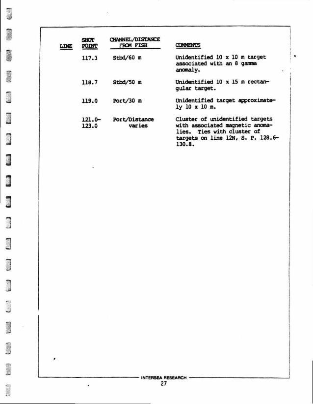
SHOT CHANNEL/DISTANCE LINE POINT FROM FISH
117.3 Stbd/60 m
118.7 Stbd/50 in
119.0 Poct/30 ffl
121.0- Poet/Distance 123.0 varies
COMMENTS
Unidentified 10 x 10 m target associated with an 8 gamma anomaly.
Unidentified 10 x 15 m rectangular target.
Unidentified target approximately 10 x 10 m.
Cluster of unidentified targets with associated magnetic anomalies. Ties with cluster of targets on line 12N, S. P. 128.6-130.8.
INTERSEA RESEARCH
27
4.0 CJNCLUSIOWS AND RECOMMENDATIONS
Baaed on these > .gh resolution data and published research, a number of conclusi' . « nd recc—iendations can be made concerning the shallow geologic conditions within the High Island Area, Block A450.
Surficial sediment thickness (above Horizon A- mapped angular unconformity) is between 66 and 92 feet (20-28 m). These sediments are probably s i l ty sands and sands deposited in the last 17,000 years. Acoustically turbid and/or transparent zones are observed on the subbottom profiler and mini-sparker records. These zones may represent reworked sediments or sediments saturated with biogenic gas. I f there is gaa in the near surface-, i t is probably not over-pressurized with respect to surrounding areas and the blow-out potential is considered to be low. However, these areas may have variable load bearing capacity with respect to surrounding sediments.
Sea floor textural variations observed on the side scan son*-records are probably the result of recent pipe laying activities and bottom current sediment reworking. Sea floor textural variations interpreted as possible biological conmunities have not been examined by a qualified marine biologist. The survey area is not subject to any biological stipulations according to the Environmental Impact Statement for the Western Gulf of Mexico Lease Offering of July, 1984. None of the regions of sea floor textural variation are considered hazardous to drilling or associated operations.
A single oil pipeline has been located and accurately plotted on Plate IV (Pigure 8). Extreme caution should be taken when working or anchoring platform support vessels near this feature.
Three subsurface faults are observed on the near trace records. These faults do not extend into the near surface sediments snd are not considered to be seismically active. However, f*«iiLs may serve as conduits for the upward migration of pressurized gas which could lead
INTERSEA RESEARCH
28
to a potential blow-out situation. These areas should be avoided when
d r i l l i n g .
The velocity anomalies (with associated velocity pull-downs)
observed on near trace data may represent gas charged sediments.
These regions are considered to have a high blow-out potential and
should be avoided when d r i l l i n g .
Numerous side scan sonar tirgata and magnetic anomalies have bevn
located in the survey area. These features are unident i f ied a-s?
should be avoided i f possible.
INTERSEA RESEARCH
29
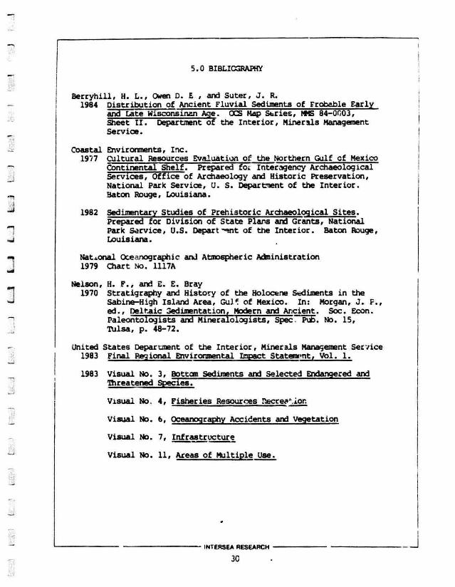
5.0 BIBLIOGRAPHY
Berryhill, H. L., Owen D. E , and Suter, J. R. 1984 Distribution of Ancient Fluvial Sediments of Frobable Early
and Late Wisconsinan Age. OCS Map Series, MMS 84-0003, Sheet I I . Department of the Interior, Minerals Management Service.
Coastal Environments, Inc. 1977 Cultural Resources Evaluation of the Northern Gulf cf Mexico
Continental Shelf! Prepared foi Interagency Archaeological Services, Office of Archaeology and Historic Preservation, National Park Service, U. S. Departraent of the Interior. Baton Rouge, Louisiana.
1982 Sedimentary Studies of Prehistoric Archaeological Sites. Prepared for Division of State Plans and Grants, National Park Service, U.S. Depart "-wit of the Interior. Baton Rouge, Louisiana.
National Oceanographic and Atmospheric Administration 1979 Chart No. 1117A
Nelson, H. F., and E. E. Bray 1970 Stratigraphy and History of the Holocene Sediments in the
Sabine-High Island Area, GuK of Mexico. In: Morgan, J. F., ed.. Deltaic Sedimentation. Modern and Ancient. Soc. Econ. Paleontologists and Mineralologists, Spec. Pub. No. 15, Tulsa, p. 48-72.
united States Department of the Interior, Minerals Management Service 1983 Final Regional Environmental Impact Statement, Vol. 1.
1983 Visual No. 3, Bottom Sediments and Selected Endangered and Threatened Species.
Visual No. 4, Fisheries Resources Recreation
Visual No. 6, Oceanography Accidents and Vegetation
Visual No. 7, Infrastructure
Visual No. Ut Areas of Multiple Use.
INTERSEA RESEARCH
30
Positioning
The survey vessel was positioned by employing a Byperange
Navigation Systeir manufactured by Integrated Oata S; terns,
Inc. ( I .D.S. I . ) in conjunction with an Argo positioning systr- from
Lorac. Tha I . D . S . I . system consisted of a dual channel Magnavox
HX1107 Satell i te receiver, a Northstar 6000 Loran C receiver and an
Integrated Data Systems host computer. Navigation calibration was
achieved by referencing the system to o i l platforms near the survey
area.
The host computer used Argo four-way range/range data to position
the survey vessel. Ths system also calculated Loran C hyperbolic and
I range/range positions and recorded satel l i te passes in order to verify
system calibration. Final adjustment of navigation data was made by
updating a l l positions by a correction factor derived from analysis of
a l l satel l i te fixes recorded during the survey. A l l data were
recorded on magnetic tape for post-cruise processing. I .D.S. I . states
that the f i n a l positioning accuracy of the system is 15 m.
INTERSEA RESEARCH
SURVEY INSTRUMENTATION fc METHODOLOGY
Six instrument systems were used to obtain the geophysical data necessary to define snallow drilling hazards. AU instruments described below were operated simultaneously within the survey area. In order to eliminate interference between the various remote sensing devices, Intersea employed an ESQ I I system, designed by Earth Physics. The ESQ I I , "Electronic Spectral Quantizer", consists of one General Processing Subsystem, three Control Processing Subsystems and ona Interface Subsystem. The ESQ I I will completely control three independent magnetic or seismic profiling systems. Functions include: firing, receiving, gating, delaying, interfacing to magnetic tape units, variable gain, operator (programmed) interfacing, digitizing and real cim processing of received signals, electronic synchronization to graphic recorders, reversal of printed data, variable area and other exaggeration printouts. The ESQ I I operates over a large range of receive times and recorder sweep speeds. All subsystems ai contained within the envelope dimensions of the basic ESQ I I .
The following is a brief description of each geophysical system operated during the survey. For more specific information on recording and processing parameters, please see the survey specification sheet in this appendix.
Echo Sounding Water depth sour .,.^s were made continuously along al l track
lines by a Simrad AR 800 echo sounder. Calibration was accomplished by the fcnr check method at the initiation and completion of the survey, and foiiowing any interruption ir. the survey when the sounding transducer was removed from the water. All measurements were compensated for vessel draft. The AR 800 has a 38 kHz transducer with a beam width of 10*.
INTERSEA RESEARCH
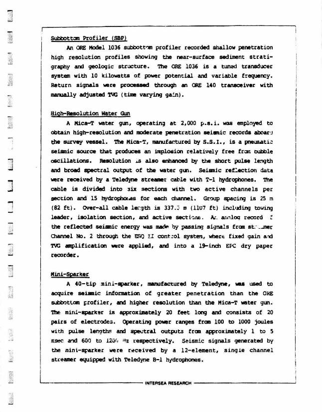
i Subbottom Profiler (SBP) j An ORE Model 1036 subbottom profiler recorded shallow penetration
high resolution profiles showing the near-surface sediment s trat i graphy and geologic structure. The ORE 1036 is a tuned transducer system with 10 kilowatts of power potential and variable frequency. Return signals were processed through an ORE 140 transceiver with manually adjusted IMS (time varying gain).
High-Resolution water Gun
A Mica-T water gun, operating at 2,000 p . s . i . was employed to obtain high-resolution and moderate penetration seismic records aboar .i the survey vessel. The Mica-T, manufactured by S .S . I . , is a pneumatic seismic source that produces an implosion relatively free from oubble oscillations. Resolution xs also enhanced by the short pulse length and broad spectral output of the water gun. Seismic reflection data were received by a Teledyne streamer cable with T-l hydrophones. The cable is divided into six sections with two active channels per section and 15 hydrophoi.es for each channel. Group spacing is 25 m (82 f t ) . Over-all cable ler.gth is 337.3 m (1107 ft) including towing leader, isolation section, and active sections. A/, analog record * the reflected seismic energy was mac** by passing signals from st.—mer Channel No. 2 through the ESQ I I control system, where fixed gain and TVG amplification were applied, and into a 19-inch EPC dry paper recorder.
Mini-Sparker A 40-tip mini-sparker, manufactured by Teledyne, was used to
acquire seismic information of greater penetration than the ORE subbottom profiler, and higher resolution than the Mica-T water gun. The mini-sparkar is approximately 20 feet long and consists of 20 pairs of electrodes. Operating power ranges from 100 to 1000 joules with pulse lengths and spectral outputs from approximately 1 to 5 msec and 600 to 1200 *z respectively. Seismic signals generated by the mini-sparker were received by a 12-element, single channel streamer equipped with Teledyne B-l hydrophones.
INTERSEA RESEARCH
Fiiterin. and graphic presentation was accomplished using the ESQ
I I central system filters/amplifiers and EPC 2201 recorder.
Side Scan Sonar Sweep A side scan sonar system (E.G.* G. SMS 960) was used to acous
tically sweep the survey area. This two-channel system (port and starboard) consisted of a towed transducer, an armored cable, and a dry paper recorder. Linear piezo-electrie crystals emitted fan-shaped acoustic beams with both sides of the submerged "fish" as it was towed above the bottcm. The 100 kHz beams were focused normal to the vessel heading and were broad enough in the vertical plan to scan from nearly below the fish out to ti.e full range of the system. Echoes reflected frcm targets to the port and starboard of the vessel were received by the towed fish, then processed and graphically dir played on a two-channel dry paper recorder.
Magnetic Searc A proton precession magnetometer (Geometries 8.1/3) with a
sensory element consisting of a toroidal!y wound coil immersed in a hydiogen-rich fluid wa0. towed 114 m (374 ft) aft of the survey vessel in order to minimize magnetic interference. The electronic console onboard processed the precession signal and recorded the magnitude of the measured total magnetic f eld. The Hewlett Packard single-chtnnel recorder operated at a sensitivity of one (1) gamma and displayed measurements at a 100 gar.-Tia (2 gamma/division) scale.
INTERSEA RESEARCH
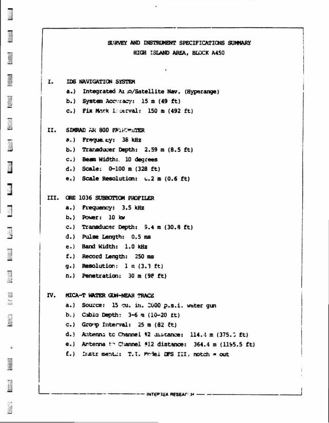
SURVEY AND INSTRUMENT SPECIFICATIONS SUMMARY
HIGH ISLAND AREA, BLOCK A450
X. IDS NAVIGATION SYSTEM
a. ) Integrated At p/Sa t e l l i te Nav. (Hyperange)
b. ) System Acc-racy: 15 m (49 f t )
c . ) Fix Mn.rH I. -trval: 150 m (492 f t )
I I . SIMRAD AK 800 P*lrOȣ,TBR
a. ) Frequecy: 36 kHz
b. ) Transducer Depth: 2.59 m (8.5 f t )
c. ) Beam Width:. 10 degrees
d. ) Scale: 0-100 m (328 f t )
e. ) Scale Resolution: c.2 m (0.6 f t )
I I I . ORE 1036 SUBBOTTOM PROFILER
a. ) Frequency: 3.5 kHz
b. ) Power: 10 kw
c. ) Transducer Depth: 9.4 m (30.8 f t )
d. ) Pulse Length: 0.5 ms
e. ) Band Width: 1.0 kHz
f. ) Record Length: 250 ms
g. ) Resolution: 1 tc (3.3 f t )
n.) Penetration: 30 m (98 f t )
IV. MICA-T WATER GUN-NEAR TRACE
a. ) Source: 15 cu. in. 2000 p . s . i . water gun
b. ) Cabio Depth: 3-6 m (10-20 f t )
c . ) Gro»p Interval: 25 m (82 Ct)
d. ) Anteniu tc Channel %2 distance: 114.4 m (375.: f t )
e. ) Antenna t" C'annel «12 distance: 364.4 m (1195.5 f t )
f. ) Irxtr ment-;: T . I . Mr-iei DPS 121, notch - out
— INTgP5£A RESEAT H

V. E.G.& G. SMS 960 100 kHz Side Scan Sonar a. ) Fiah Height Above Seafloor: 10-20 m (33-65 ft) b. ) Sweep Rate: 200 m (656 ft;/channel c. ) Distance Fron Antenna: 42.7 m (271 ft) d. ) Cable Out: 53.3 ra (175 ft) e. ) Resolution: 1-2 m (3-€ ft)
VT. GEOMETRICS PROTON PRECESSION MAGNETOMETER a. ) Sensitivity: 1 gamma b. ) Sample Rate: 2/12.5 m (41 ft) c. ) Background Noise: + 1 gamma d. ) Source Depth: 25.9 m (84.9 ft) e. ) Distance From Antenna: 143.4 m (470 ft) f. ) Cable Out: 114 m (374 ft)
VII. 40-TIP MINI-SPARKER a. ) Power: 1000 Joules b. ) Bandpass: 150-2000 Hz c. ) Record Length: 250 ms d. ) Source Setback/depth: 39.4 m (129.3 ft)/1.0 m (3.3 ft) e. ) Receiver Setback/depth: 39.4 m (129.3 ft)/1.0 » (3.3 ft) f. ) Resolution: 2.0 m (6.6 ft) g. ) Penetration: 200 ms
INTERSEA RESEARCH
tSJ &s&) fc£eH WW K-*l ttssJ t ~l I I ' t - 1 S*-^ **?4J*
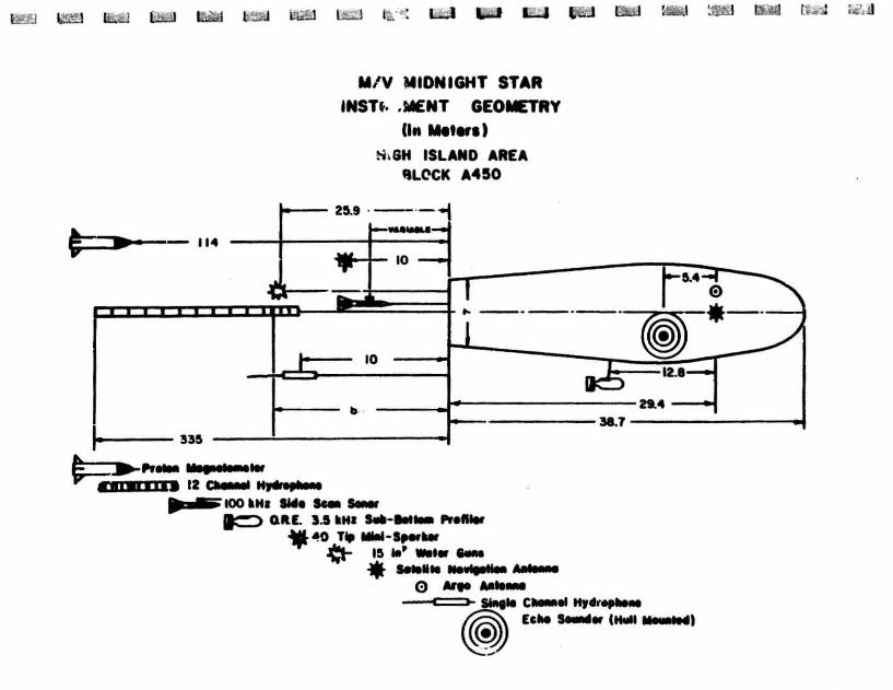
M/V MIDNIGHT STAR INSTt. .MENT GEOMETRY
(In M i t t r t )
S.GH ISLAND AREA BLOCK A450
IOO kt4| SMt Sean § C 3 QUE. 3 5 kHi Set-fMteei Profile*
-Mfr 40 Tip MM-SM'Ur J{rt~ IS *»' •«*•
*•*•••§ Ne»HeMn O Arte Afliewie
Single ClMMel HydVophane Echo Sound* (Hell


PLACID OIL COMPANY SUITE 1900
1440 CANAL STREET NEW ORLEANS, LOUISIANA 70112
(504) 525-7921
.a ,uary 29, 1986
Regional Suoervisor for Rules and Production Mineral Management -erv.ce LMted Statps Department of -he Interior P. 0. Box /y*A Metairie, Louisiana 70010
RE: Shallow Hazards Survey OCS-G-7334 Block A-450 High Island Area Offshore, Texas
Gentlemen:
A roultisensor high resolution geophysical survey was conducted over Block A-450 during December, 1984. This survey was done by Intersea Research under co tract to Texaco, Inc.
I have reviewed the collected data and can see no Indications of d r i l l ing hazards at any of tne three proposed locatics li«:'ed below:
Well Location Water Depth PTVD
"A" 4250' FWL, T200' FNL 156' 7500' "B" 6500' FEL, 8000' FNL 158' 7500' "C" 4000' FWL, 1500' FNL 152' 7500'
We c.re submitting under separate cover copies of the high resolution geophysics 'Ha adjacent to each of these locations.
We will n> .iin the original data on f i l e in this office should further review becom* necessary.
Sincerely,
/-John,C. Farris District Manager
PLALMO--JIL COMPANY
Durwood Craft / District Geophysicist
DC/bcr
* * * * * * *
AIR QUALITY REVIEW For
High Island Area Block A450 OCS-6-7334
Placid Oil Conpany 3900 Thanksgiving Tower
Dallas, Texas 75201
Submitted To James Jordan
Administrative Assistant
January 29, 1986
* * *
Prepared by: JOHN E. CHANCE & ASSOCIATES, INC.
Regulatory and Environmental Division Lafayette, Louisiana Project No. 86-8009
John E. Chance «fft Assoc-, Inc.
PROJECTED AIR EMISSION SCHEDULE FOR EXPLORATION PROJECT
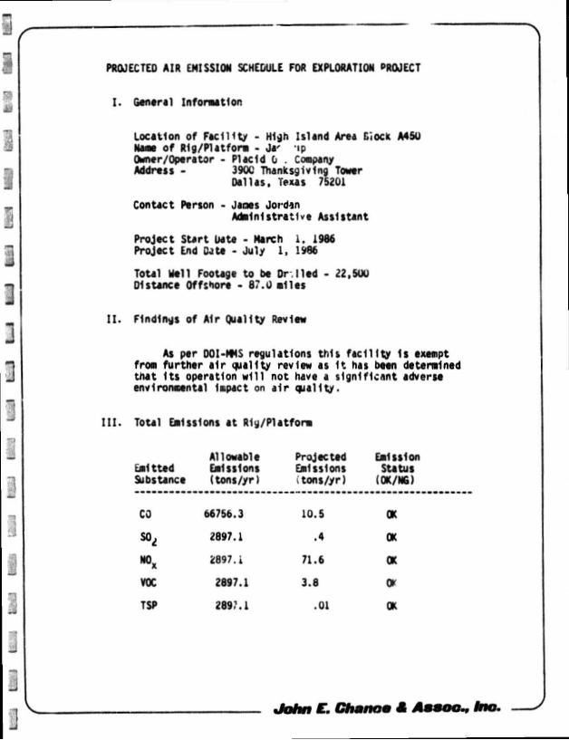
I. General Information
Location of Facility - High Island Area dock A4SU Naae of Rig/Platform • Ja' ip Owner/Operator - Placid 0 . Coapany Address - 390C Thanksgiving Tower
Dallas, Texas 75201
Contact Person - Janes Jordan Administrative Assistant
Project Start Date - March 1. 1986 Project End Data - July 1, 1986
ToUl Nell Footage to be Or Med - 22,SOU Distance Offshore - 87.U milts
I I . Findings of Air Quality Review
As ptr DOI-MMS regulations this facil i ty 1s exempt from further air quality review as I t has been determined that I ts operation will not have a significant adverst environmental Impact on air quality.
I I I . Toul Emissions at Rig/Platform
Allowable Projected Emission emitted Emissions Emissions Status Substance (tons/yr) tons/yr) i OK/NG)
CO 66756.3 10.5 OK
» t 2897.1 .4 OK
*>* *897.i 71.6 OK
VOC 2897.1 3.8 o> TSP 2897.1 .01 OK
John €. Chmnom et Assoc., Inc.
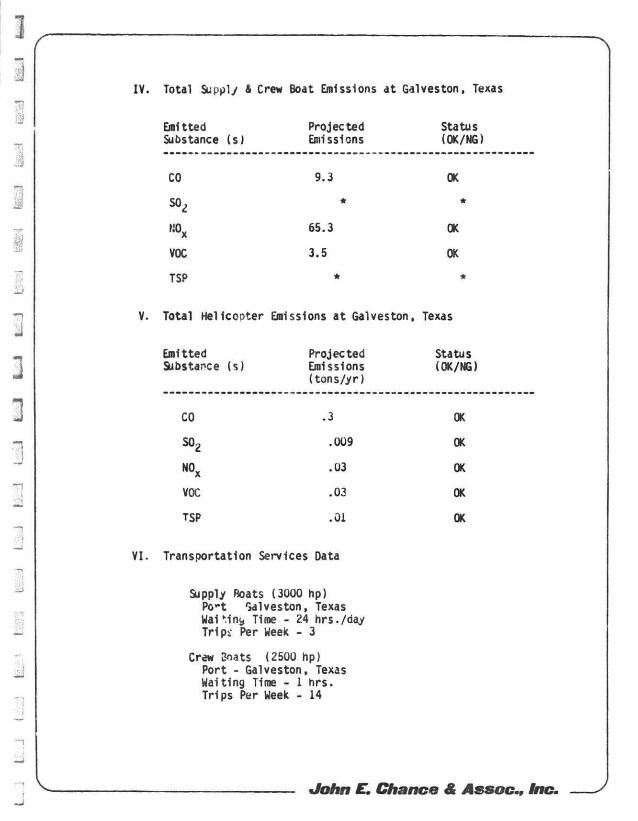
IV. Total Supply A Crew Boat Emissions at Galveston, Texas
Emitted Projected Status Substance (s) Emissions (OK/NG)
CO 9.3 OK
SO * *
M0X 65.3 OK
VOC 3.5 OK
TSP * *
V. Total Helicopter Emissions at Galveston, Texas
Emitted Projected Status Substance (s) Emissions (OK/NG)
( tons/yr)
CO .3 OK
so2 .009 OK
N O x .03 OK
VOC .03 OK
TSP .01 OK
VI. Transportation Services Data
Supply Boats (3000 hp) Po-t Galveston, Texas Wa1 Mnt, Time - 24 hrs./day Tr ip i Per Week - 3
Crew Boats (2500 hp) Port - Galveston, Texas Waiting Time - 1 hrs . Trips Per Week - 14
John E. Chance £ Assoc., Inc.
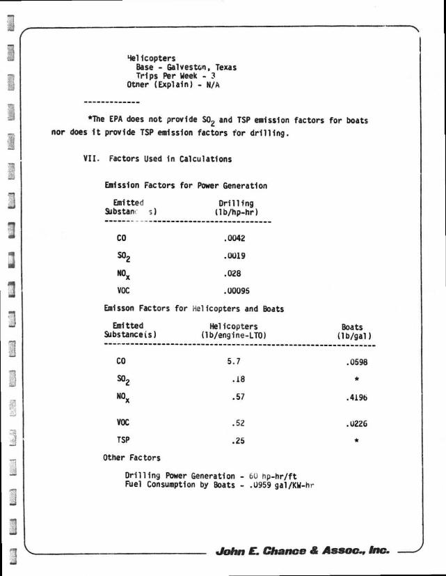
Helicopters Base - Galveston, Texas Trips Per Week - 3
Otner (Explain) - N/A
•The EPA does not provide S02 and TSP emission factors for boats
nor does 1t provide TSP emission factors tor d r i l l i n g .
V I I . Factors Used In Calculations
Emission Factors for Power Generation
Emitted D r i l l i ng Substan- s) l lb /hp-hr )
CO .0042
S02 .0019
N0X .028
VOC .00095
Emlsson Factors for Helicopters and Boats
Emitted Helicopters Boats Substanceis) (lb/englne-LTO) ( lb /ga l )
CO 5.7 .0598
S02 .18 *
N0X .57 .4196
VOC .52 .U226
TSP .25 *
Other Factors
D r i l l i n g Power Generation - 60 hp-h r / f t Fuel Consumption by Boats - .0959 gal/KW-hr
J o h n E . C h a n c e £ A s s o c - , Inc.
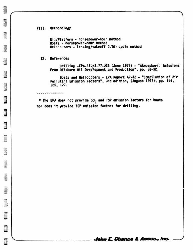
VI I I . Methodology
Rig/Platform - horsepower-hour method Boats - horsepower-hour method Hel : ters - landing/takeoff (LTO) cycle method
IX. References
Dri l l ing -EPA-45J/3-77-026 (June 1977) - "Atmospheric Emissions From Offshore Oil Development and Production", pp. 81-92.
Boats and Helicopters - EPA Report AP-42 - "Compilation of A1r Pollutant Emission Factors", 3rd edit ion, (August 1977), pp. 116, 125, 127.
* The EPA doer not provide S02 and TSP emission factors for boats nor does I t provide TSP emission factor: for d r i l l i ng .
^ John E. Chance & Assoc., Inc.